Effects of Water-Cooling on the Mechanical Properties and Microstructure of 5083 Aluminum Alloy during Flame Straightening

1
Welding Laboratory A221, School of Material Science and Technology, Hebei University of Science and Technology, Shijiazhuang 050018, China
2
Technology Center, China State Shipbuilding Corporation Huangpu Wenchong Shipbuilding Company Limited, Guangzhou 510715, China
*
Authors to whom correspondence should be addressed.
Metals 2018, 8(9), 692; https://doi.org/10.3390/met8090692
Submission received: 20 July 2018
/
Revised: 27 August 2018
/
Accepted: 31 August 2018
/
Published: 3 September 2018
Abstract
:Aluminum alloy 5083 is widely used in the fabrication of marine vessels. This paper presents the difference in mechanical properties and microstructure between natural-cooling and water-cooling after flame straightening. Under the synchronous water-cooling process, the peak temperature of the heating center was unchanged, but the peak temperatures of the other areas decreased obviously and the cooling rate increased substantially. The microhardness of the rectified area was lower than that of the base metal. The average microhardness decreased about 4.4 HV when using synchronous water-cooling, whereas the average microhardness of the specimen without using water-cooling was 11.6 HV lower than the base metal. Tensile test results show that the yield strength and the ultimate strength of synchronous water-cooling specimen increased 9.16 MPa and 1.64 MPa on average, but the elongation rate decreased compared with the specimen only under flame straightening. The results of metallographic tests show that the grain growth tendency and precipitation phase size and quantity reduced after using synchronous water-cooling.
1. Introduction
The rapid development of the shipbuilding industry has caused the introduction of stricter requirements on hull manufacturing [1]. Aluminum alloy plays an important role in the fabrication of lightweight high-speed marine vessels due to its small specific gravity and elastic modulus, excellent corrosion resistance, good workability, non-magnetic, and low temperature performance. The thermal conductivity of aluminum alloy is five times higher than steel, and its linear expansion coefficient is twice that of steel, so the deformation in aluminum alloy welding is more serious than steel [2]. If welding deformation is not well controlled, it causes difficulties in hull assembly and in the installation of main auxiliary machine systems, or even to failure to meet quality control standards [3]. In the shipbuilding industry, the control of aluminum alloy welding deformation is an urgent problem to be solved [4,5]. Aluminum alloy 5083 has excellent mechanical properties amongst the non-heat-treatable alloys, due to the magnesium effect. Magnesium is one of the major alloying elements; its mechanical properties improve with the increase in magnesium content, but the corrosion resistance decreases with the increase in magnesium content [6]. Therefore, magnesium content is generally controlled at about 5 wt % as a marine aluminum alloy. In addition, silicon also reduces the corrosion resistance of the alloy, so the silicon content is normally controlled below 0.5 wt % [7].
In recent years, researchers have studied the aluminum alloy welding deformation straightening technique and its influences [8,9]. The flame rectification process after welding has been widely used in actual productive process owing to its low-cost and easy operation. Comparing the performance of 6N01-T5 with 7N01-T5 at different heating temperatures, Xiong [10] suggested that the suitable thermal rectification temperature of 6N01 is 200–250 °C and that of 7N01 is 330–400 °C. It was pointed out that excessive temperature would cause the softened zone to extend to the base metal and quenched zone. Jiang et al. [11] analyzed the changes in mechanical properties and microstructure of metal inert-gas (MIG) welded joint of 6005A aluminum alloy after straightening with different flame heating temperatures. The results showed that the hardness and tensile strength of the welded joint did not change when the heating temperature was lower than 200 °C. When the heating temperature exceeded 200 °C, the hardness and tensile strength decreased significantly because of the growth of grains, and the softened zone broadened. All these studies focused on the influences of the highest temperature on the microstructure and mechanical properties of aluminum alloy during the heating process, without considering the impact of high temperature dwell time. In this paper, the flame straightening of aluminum alloy 5083 was studied. The effects of synchronous water-cooling (SWC) on the temperature distribution and the microstructure and mechanical properties of aluminum alloy were analyzed and compared, which provides a basis for the application of flame straightening with synchronous water-cooling. SWC is a method that uses flowing water to immediately cool the straightening zone after flame straightening.
2. Materials and Methods
2.1. Materials
The material employed in the tests was aluminum-magnesium alloy 5083 plates with dimensions of 500 × 300 × 4 mm. The chemical composition is shown in Table 1.
2.2. Experimental Procedure
In order to exclude the interference caused by inconsistent drilling depth, poor contact of thermocouples, and other external factors, the temperature distribution was measured during static heating. k-type thermocouples were installed in the blind holes at a 3-mm depth to measure the temperature of the three channels (Channel 1(CH 1), Channel 2(CH 2) and Channel 3(CH 3) in Figure 1). The distances from CH 1 to CH 2 and CH 2 to CH 3 were each 10 mm [12].
In this study, an oxyacetylene flame was applied to the plate surface by Z swing to deform the plates, as shown in Figure 2. According to the experimental requirements, the speed of the flame heating was constant, the angle between the nozzle and the plates was not greater than 45°, and the distance between the nozzle and the plates was 20–25 mm. The only difference between the two plates was that synchronous water-cooling was used on the surface of the second plate immediately after flame straightening.
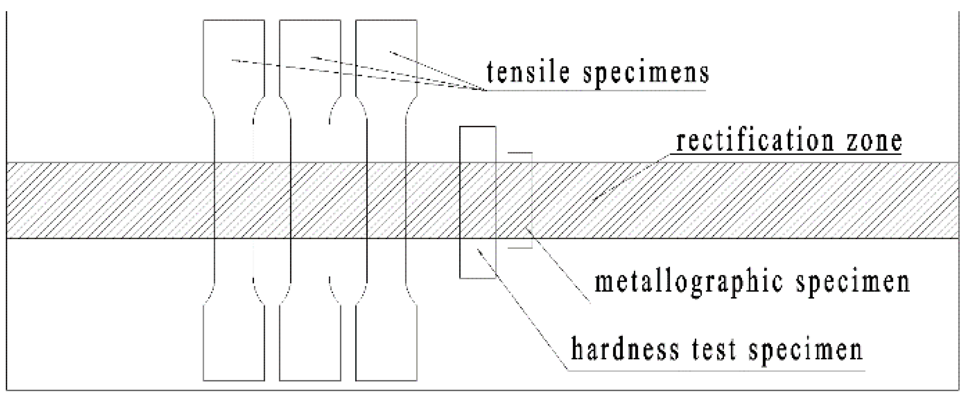
The metallographic specimens, hardness test specimens, and tensile test specimens were cut from the two plates using an electrical discharge machining. The metallographic specimen was 13 × 50 × 4 mm, the hardness specimen was 19 × 80 × 4 mm, and the tensile specimen′s shape is shown in Figure 3. The sampling position of each specimen is shown in Figure 4.
Tensile testing was carried out in accordance with ISO 6892-1:2009. Three samples were tested under each condition. The tests were carried out at room temperature using a computerized Zwick Z100THW electromechanical testing machine (Zwick/Roell, Ulm, Germany). The fracture surfaces were observed by using TESCAN-VEGA3 scanning electron microscope (TESCAN, Brno, Czech).
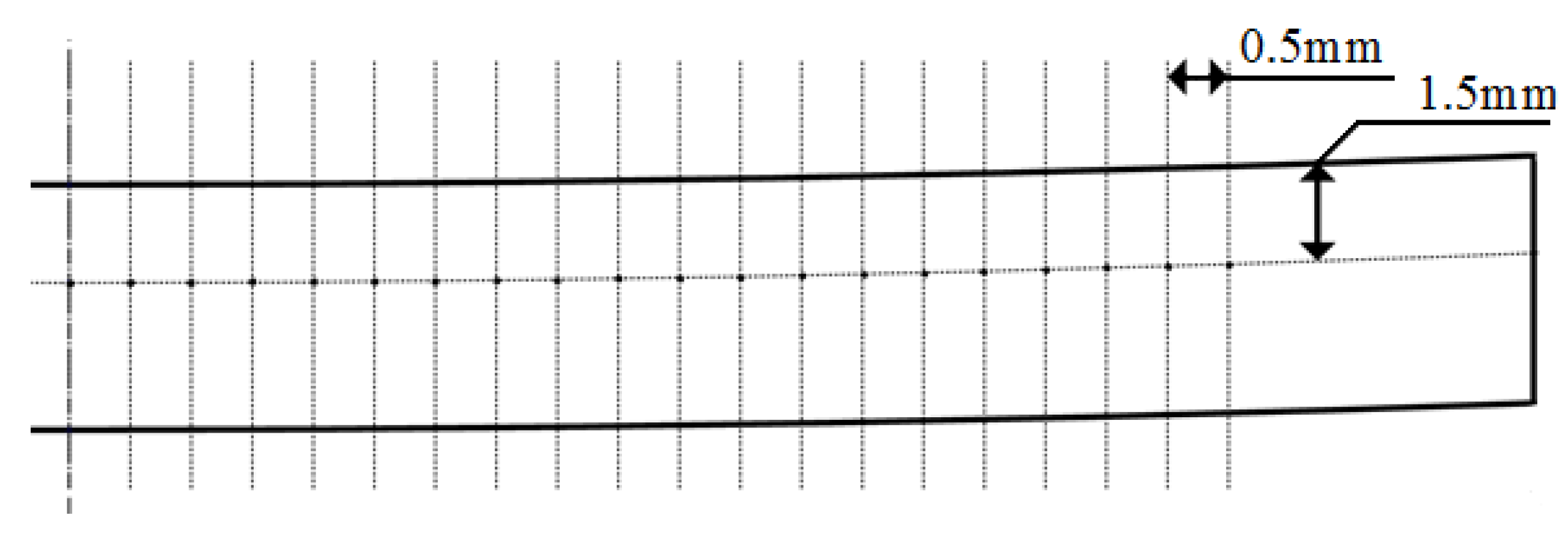
Vickers microhardness was measured under a load of 500 g for 10 s on the cross-section perpendicular to the rectification direction using a THV-1MD automatic testing machine (Yanrun, Shanghai, China). The locations of the microhardness test points are shown in Figure 5. The distance of the row away from the top surface of the plate was 1.5 mm, and the interval between each point was 0.5 mm.
The samples were polished manually up to 1 or 3 microns and then finished by electrolytic polishing. The etchant was Barker’s reagent. After electrolytic polishing, the microstructure of the specimens was investigated using a Zeiss microscope (Oberkochen, Germany).
3. Results and Discussion
3.1. Temperature Profile
The temperature profiles of each channel were obtained during the flame rectification process to analyze the characteristics of the thermal cycle, as shown in Figure 6. The results showed that the peak temperature decreased with increasing distance from the heating center, so the peak temperature of CH 1 was the highest among the three channels. Compared with the flame straightening, the peak temperatures of CH 2 and CH 3 for SWC were 37 °C and 39 °C lower, respectively; whereas the peak temperature of CH 1 was approximately unchanged. Moreover, compared with flame straightening, the high-temperature dwelling time under SWC substantially decreased. For flame straightening, the dwelling times above 150 °C and 100 °C were 35.8 s and 63 s, respectively; whereas the values under SWC were only 10.9 s and 15.8 s, respectively. The increasing rate of temperature under SWC was the same as that under flame straightening, whereas the cooling rate under SWC was obviously higher than under flame straightening. The time required to reduce the temperature from the peak temperature to room temperature under SWC was less than half of that under flame straightening. All of the aforementioned results clearly indicate that the SWC affected the high-temperature dwelling time.
3.2. Tensile Properties
Figure 7 shows macroscopic images of the samples after fracture. The fractures of the three tensile specimens with flame straightening were located in the central position of the straightening zone. However, the fractures of the specimens with SWC were not concentrated in the central position of the straightening zone. For example, specimen 2 fractured at the rectification edge. The results of the tensile test of the specimens under different conditions are shown in Table 2. As we know from Table 2, the ultimate strength of the two states was not significantly different, but the yield strength was different. The ultimate strength and yield strength under SWC were 1.64 and 9.16 MPa higher than those under the flame straightening on average, respectively. The elongation of the specimen with SWC was 17.35%, whereas the elongation of the specimen with the flame straightening was 19.44% on average. Compared with base metal, the ultimate strengths of the two states were basically consistent with the base metal. The yield strength under SWC was closer to the yield strength of the base metal [13].
3.3. Fractography
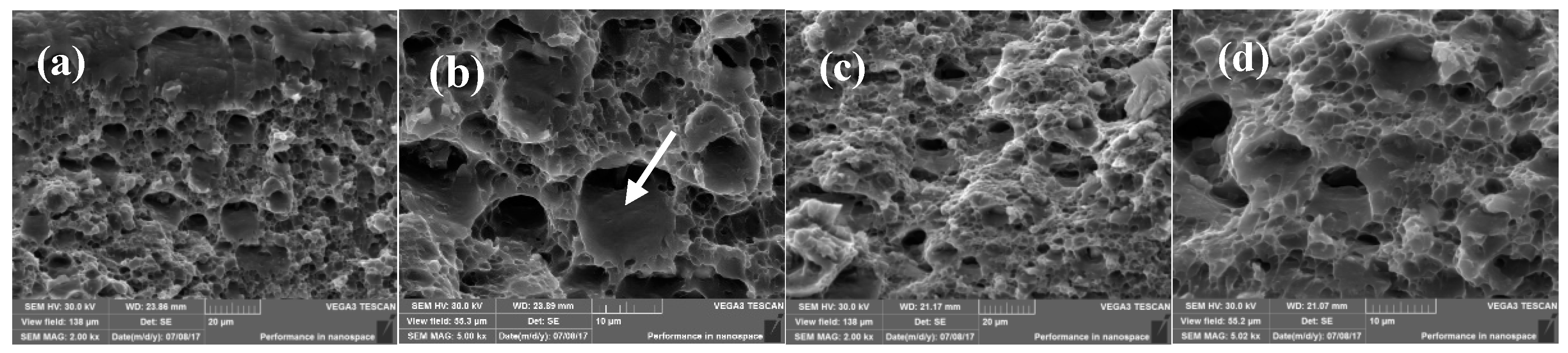
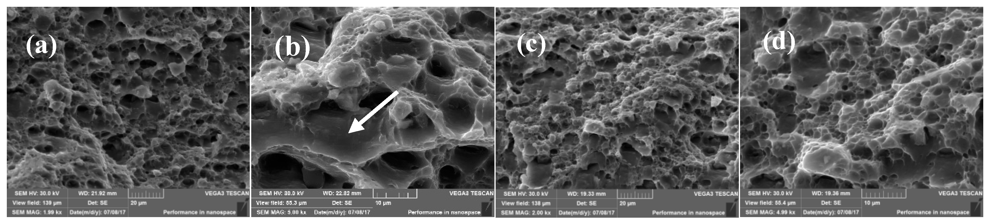
Figure 8 and Figure 9 show the scanning electron microscopy (SEM) fractographs of the fracture surface of the samples under different conditions. Figure 8a,b and Figure 9a,b were close to the rectification surface, Figure 8c,d and Figure 9c,d were near to the bottom of the samples. From the macroscopic view, the fracture surface appeared to be fibrous, and the whole section was at an angle of 45° to the principal stress [14]. The fracture surfaces of the samples of the two states were covered with equiaxed dimples of various sizes. The typical dimples of the fracture surfaces indicated that the fracture morphology was a ductile feature. Because the growth rate of micropores was significantly changed under normal stress along three directions without uniaxial tension, and a large number of equiaxed dimples were produced [15] (Figure 8 and Figure 9a,c). After magnifying 5000 times, these marks were snakelike slippages (Figure 8 and Figure 9b). It can be seen that the small dimples crowded around the large dimples from the fracture morphology of the sample with SWC, and the fracture morphology of the sample with flame straightening, were relatively uniform in size, but larger and shallower. Since the dimple size is related to the spacing of the second phase particles, the increase in the dimple can be explained by the increased distance of the second phase and the dispersed distribution. There was little difference between the fracture morphology (Figure 8 and Figure 9c,d); though the bottom was far from the flame straightening surface, the degree of heat affected was less.
3.4. Microhardness Line
Figure 10 depicts the microhardness profiles of the samples under different states as well as the base metal. It can be seen that the microhardness of the two states were lower than that of the base metal. However, the microhardness of the SWC was closer to that of the base metal, and its average only decreased by 4.4 HV, whereas the flame straightening was 11.6 HV lower than that of the base metal on average. Compared with the two states, the microhardness of the specimen with flame straightening had a large gradient, and its average was about 7 HV lower than that of the SWC.
3.5. Microstructure
Figure 11 shows the position where the pictures of the metallographic microstructure were taken. The comparison results of the metallographic microstructure are shown in Figure 12 and Figure 13, showing transverse sections of SWC and the flame straightening, respectively.
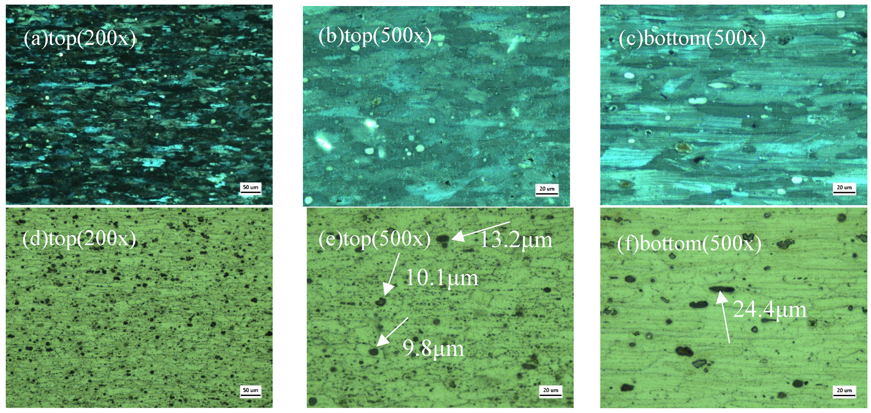
Under SWC, the microstructure appeared similar to the original, with an elongated grain structure presented. The change in the grain shape in the thickness direction was not obvious (Figure 12a–c). It can be considered that the grains did not grow significantly. The small amount of β (Mg5Al8) precipitates (the black precipitate indicated by the arrow) appeared in the matrix [16], and the size of the precipitate phases was mostly small (Figure 12d–f). This effect is shown in Figure 12e. After SWC, the precipitates were smaller and more dispersed. The measured data showed that the average size of the precipitates at the bottom was about 25 μm, and the average size of precipitates after SWC was about 13 μm.
Without SWC, the grain size increased significantly in the thickness direction (Figure 13a,b). The microstructure did not appear similar to the original, and the elongated grain structure disappeared. The higher heat input led to a larger grain dimension, whether on the rectification surface or the reverse side, as shown in the micrographs in Figure 13c. The grains looked like blocks rather than long strips, and the original rolling organization state was essentially lost. At the same time, the amount of black precipitates on the matrix increased, the size of precipitates increased, and the distribution of precipitates was more decentralized (Figure 13d–f). Because of the too-long dwell time at high temperature, the surrounding supersaturated solute elements diffused and grew to the precipitated phase, which resulted in a decline in the original solid solution strengthening effect. The measured data showed that the average size of the precipitates at the bottom was about 25 μm, and the average size of precipitates after flame straightening was about 20 μm.
Comparing Figure 12 and Figure 13, we found that the recrystallization was not obvious at the near-surface of the specimen with SWC. In addition, the β precipitate was rhabditiform or spherical in the material, and there was no observed definite distribution rule, but it appeared randomly at grain boundary and in the grain. It can be seen from the literature [17] that the β precipitates tend toward nucleation and growth at dislocation and dislocation entanglement. According to the literature [18,19], the equilibrium phase of Al-Mg alloy is β precipitate, and the β precipitate is rhabditiform, which is consistent with the shape in Figure 12 and Figure 13.
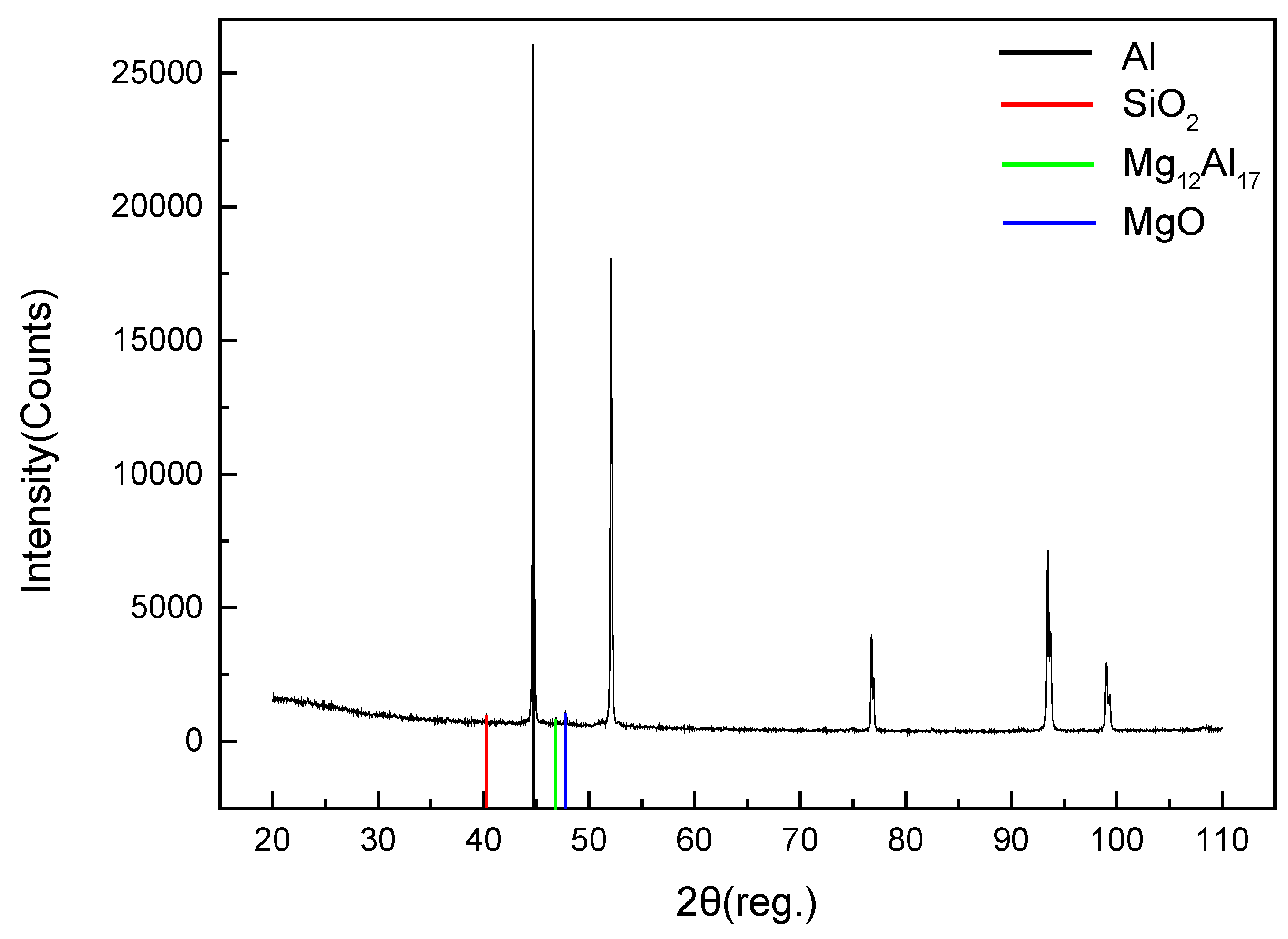
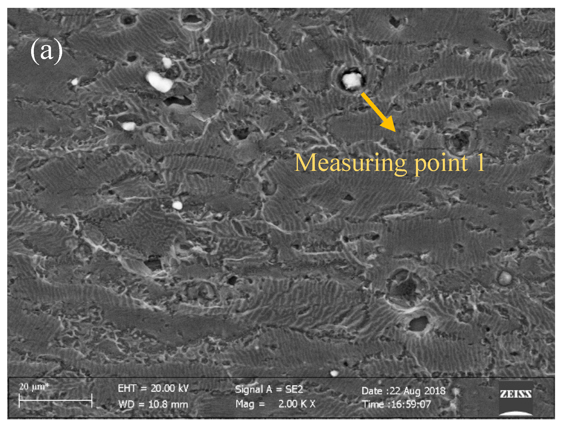
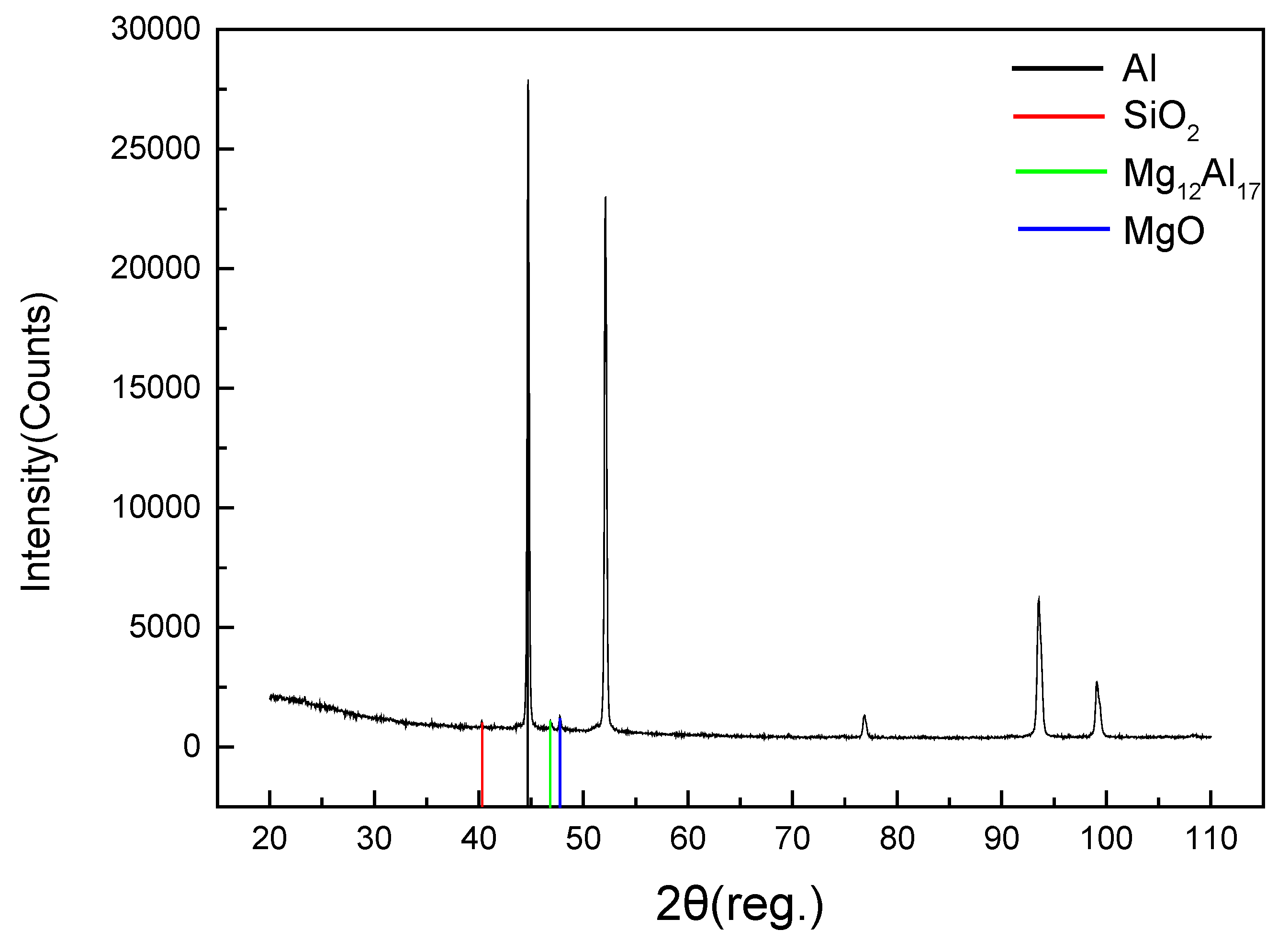
In order to identify the type of precipitates and enhance the identification provided by the literature, SEM analysis was performed. The results are shown in Figure 14 and Figure 15. The composition of the precipitated phases in the two states was the same, but the mass percentage of each component was different. Therefore, the precipitation was consistent. The existence of oxygen was due to the electrochemical polishing of specimens. The other elements may be constituents of the precipitates because the SEM only determined the composition of the precipitates and could not accurately obtain the phase results. X-ray diffraction (XRD) was used to analyze the phases. As shown in Figure 16 and Figure 17, the types of precipitates were consistent, and the ratio of magnesium and aluminum was 12:17.
The grain growth and the coarsening of the precipitated phase were the main reasons for the change in mechanical properties after flame straightening [20,21,22]. The grain growth weakened the effect of intercrystalline strengthening. The coarsening of the precipitated phase reduced the number of solute elements in the matrix and the effect of the solid solution strengthened. Therefore, when water-cooling was not used, the yield strength, tensile strength, and hardness of the specimen decreased, while the elongation increased slightly.
Synchronous water-cooling can significantly reduce the high temperature dwell time in flame straightening. Using this process, recrystallization and growth were effectively inhibited, the diffusion of solute elements and the coarsening of the precipitated phase were reduced, and the strength and hardness of the aluminum alloy material were well maintained.
4. Conclusions
In this paper, the effect of the synchronous water-cooling on the mechanical properties and microstructure of 5083 aluminum alloy by flame straightening was investigated. Based on the analysis described above, the following conclusions are drawn. Compared with flame straightening, the peak temperature of the heating center was unchanged but the peak temperatures of other areas for the SWC decreased obviously. Additionally, the cooling rate increased substantially.
The yield strength and the ultimate strength of the synchronous water-cooling specimen increased by 9.16 MPa and 1.64 MPa on average, but the elongation rate decreased. Synchronous water-cooling effectively reduced the dwell time of high temperature, restrained the recrystallization and growth of grains, and reduced the diffusion of solute elements and the coarsening of the precipitated phase, so that the microhardness of the specimen with SWC was closer to the base metal, which was about 7 HV higher than that of the specimen with flame straightening. The results show that the surface grains of SWC specimen did not grow significantly; the precipitates in the matrix were fewer and smaller. For the specimen with the flame straightening, the grain grew longer, but the distribution was more dispersed.
Author Contributions
Conceptualization: Z.L. and D.Y.; Data curation: C.C. and X.W.; Formal analysis: C.C. and X.W.; Project administration: Y.R., H.W. and D.Y.; Supervision: D.Y.; Writing—original draft: C.C.; Writing—review & editing: Z.L.
Funding
The authors gratefully acknowledge the financial support by China Postdoctoral Fund Project (No.2016M590821), Guangdong Key Laboratory of Enterprise Advanced Welding technology for ships (No.2017B030302010), National Natural Science Foundation of China (Grant No. 51205106), Natural Science Foundation of Hebei Province (Grant No. E2016208077) and Department of Education Hebei Province (Grant No. QN2018003).
Acknowledgments
First and foremost, I would like to show my deepest gratitude to my tutor, Z.L., a respectable, responsible and resourceful scholar, who has provided me with valuable guidance in every stage of the writing of this thesis. Without his enlightening instruction, impressive kindness and patience, I could not have completed my thesis. His keen and vigorous academic observation enlightens me not only in this thesis but also in my future study. I would also like to thank all my teachers who have helped me to develop the fundamental and essential academic competence. My sincere appreciation also goes to the teachers and students from the School of Material Science and Technology, Hebei University of Science and Technology, who participated this study with great cooperation. Last but not least, I′d like to thank all my friends, especially my five lovely roommates, for their encouragement and support.
Conflicts of Interest
The authors declare no conflict of interest.
References
- Stannard, D.M.; Smith, B.L. Recent advances for use of aluminum offshore. In Proceedings of the 8th International Conference on Offshore Mechanics and Arctic Engineering, Huston, TX, USA, 19–23 March 1989; pp. 299–307. [Google Scholar]
- Xue, J.; Liu, J. Research on current state and prospect of welding deformation and deformation control methods for China′s high-speed train aluminum alloy carbody. Hot Work. Technol. 2012, 41, 201–208. [Google Scholar]
- Zhang, Z.Y.; Jiang, H.B.; Yu, C.Q. Automated flame rectification process planning system in shipbuilding based on artificial intelligence. Int. J. Adv. Manuf. Technol. 2006, 30, 1119–1125. [Google Scholar] [CrossRef]
- Deng, D.; Murakawa, H.; Liang, W. Numerical simulation of welding distortion in large structures. Comput. Methods Appl. Mech. Eng. 2007, 19, 4613–4627. [Google Scholar] [CrossRef]
- Jung, G.; Tsai, C. Plasticity-based distortion analysis for fillet welded thin-plate T-joints. Weld. J. 2004, 83, 177–187. [Google Scholar]
- Davis, J.R. Corrosion of Aluminum and Aluminum Alloys; ASM International: Cleveland, OH, USA, 1999. [Google Scholar]
- Chen, X.L. Corrosion Behavior, Yield Behavior and High Temperature Deformation Behavior of Marine High Magnesium Aluminum Alloy. Master’s Thesis, Central South University, Guangzhou, China, 2009. [Google Scholar]
- Li, S.; Guo, D.; Dong, H.D. Effect of flame rectification on corrosion property of Al-Zn-Mg alloy. Trans. Nonferrous Met. Soc. China 2016, 27, 250–257. [Google Scholar] [CrossRef]
- Jiang, L.; Wang, Y.J.; Liu, A.J.; Wei, X.J. Effect of flame straightening on microstructures and properties of welded Joint of aluminum alloy for high-speed train. Trans. Mater. Heat Treat. 2003, 24, 59–61. [Google Scholar]
- Xiong, Z.L. Effect Mechanism of Heat-Straightening Temperature on Microstructure and Properties of Aluminum Alloy Joint in High-Speed Trains. Master’s Thesis, Harbin Institute of Technology, Harbin, China, 2014. [Google Scholar]
- Jiang, L.; Wei, X.J.; Yao, G.C.; Wang, D.Q. Effect of Flame Heating Temperature on Properties of Welded Joint of 6005A Aluminium Alloy. J. Northeast. Univ. 2003, 24, 365–368. [Google Scholar]
- Cao, Y.; Li, H.Y.; Liang, Z.M.; Wang, D.L. Effect of Water Cooling on the Microstructure and Mechanical Properties of 6N01 Aluminum Alloy P-MIG-Welded Joints. J. Mater. Eng. Perform. 2017, 26, 3929–3938. [Google Scholar] [CrossRef]
- Xia, S.L.; Ma, M.; Zhang, J.X.; Wang, W.X.; Liu, W.C. Effect of heating rate on the microstructure, texture and tensile properties of continuous cast AA 5083 aluminum alloy. Mater. Sci. Eng. A 2014, 609, 168–176. [Google Scholar] [CrossRef]
- Lacalle, R.; AÁlvarez, J.; Ferreño, D.; Portilla, J.; Ruiz, E.; Arroyo, B.; Gutiérrez-Solana, F. Influence of the flame straightening process on microstructural, mechanical and fracture properties of S235 JR, S460 ML and S690 QL structural steels. Exp. Mech. 2013, 53, 893–909. [Google Scholar] [CrossRef]
- Li, S.; Dong, H.G.; Shi, L.; Li, P.; Ye, F. Corrosion behavior and mechanical properties of Al-Zn-Mg aluminum alloy weld. Corros. Sci. 2017, 123, 243–255. [Google Scholar] [CrossRef]
- Shankar, K.; Wu, W.D. Effect of welding and weld repair on crack propagation behaviour in aluminium alloy 5083 plates. Mater. Des. 2002, 23, 201–208. [Google Scholar] [CrossRef]
- Hamana, D.; Bouchear, M.; Betrouche, M.; Derafa, A.; Rokhmanov, N.Y. Comparative study of formation and transformation of transition phases in Al–12 wt.% Mg alloy. J. Alloys Compd. 2001, 320, 93–102. [Google Scholar] [CrossRef]
- Carroll, M.C. Improvements to the Strength and Corrosion Resistance of Al-Mg-Mn Alloys of Near-AA5083 Chemistry. Ph.D. Thesis, The Ohio State of USA University, Columbus, OH, USA, 2001. [Google Scholar]
- Sheppard, T.; Parson, N.C.; Zaidi, M.A. Dynamic recrystallization in Al-7Mg alloy. Met. Sci. 1983, 17, 481–490. [Google Scholar] [CrossRef]
- Takeda, M.; Ohkubo, F.; Shirai, T.; Fukui, K. Stability of Metastable Phases and Microstructures in the Ageing Process of Al-Mg-Si Ternary Alloys. Mater. Sci. 1998, 33, 2385–2390. [Google Scholar] [CrossRef]
- Lu, H.; Shi, L.; Dong, H.G.; Li, S.; Guo, D.; Tao, C. Influence of flame rectification on mechanical properties of Al-Zn-Mg alloy. J. Alloys Compd. 2016, 689, 278–286. [Google Scholar] [CrossRef]
- Guo, D. Influence of Flame Correction of Microstructure and Properties of Al-Zn-Mg Alloy. Master’s Thesis, Dalian University of Technology, Dalian, China, 2015. [Google Scholar]
Figure 1.
Schematic of temperature field measurement (mm).
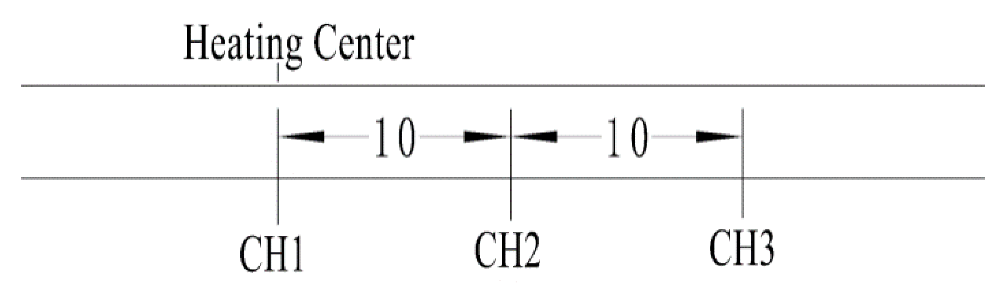
Figure 2.
Front of test panel: (a) flame straightening; (b) synchronous water-cooling.
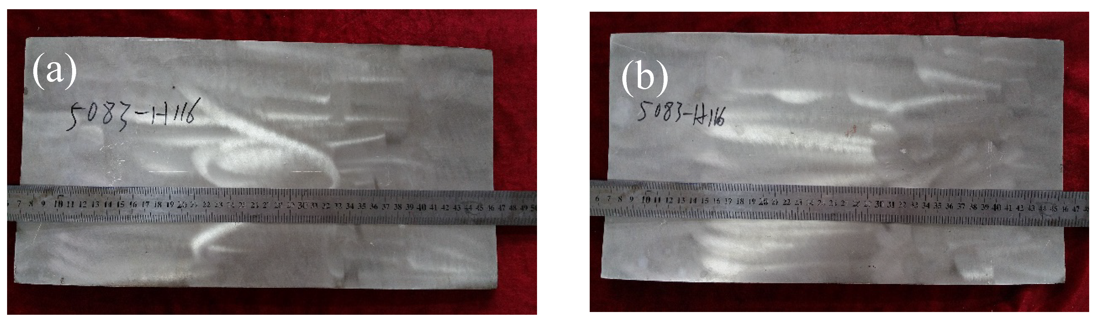
Figure 3.
Shape of tensile specimen (mm).
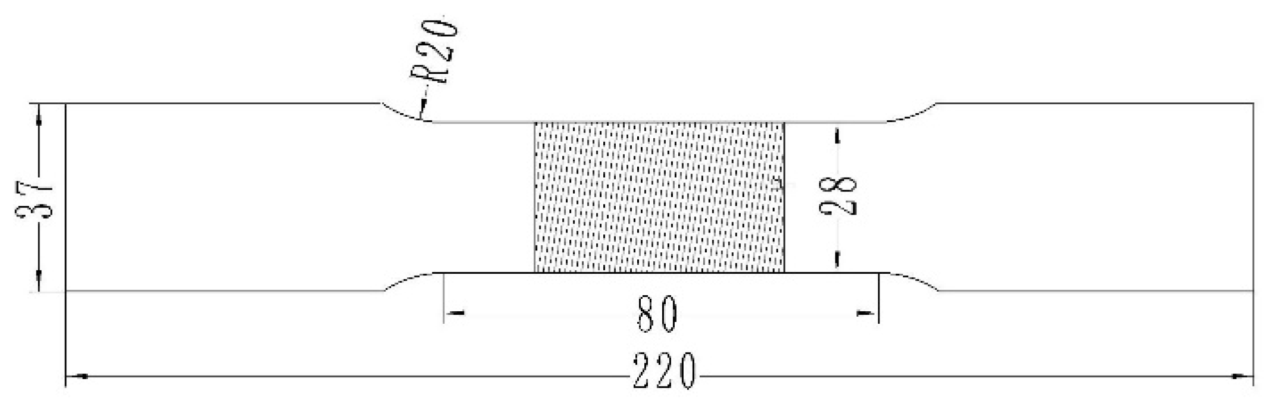
Figure 4.
Sampling point of specimens.

Figure 5.
Measurement position of hardness.

Figure 6.
Temperature profiles of CH 1, CH 2, and CH 3 under different conditions: (a) CH 1, (b) CH 2, and (c) CH 3.
Figure 6.
Temperature profiles of CH 1, CH 2, and CH 3 under different conditions: (a) CH 1, (b) CH 2, and (c) CH 3.
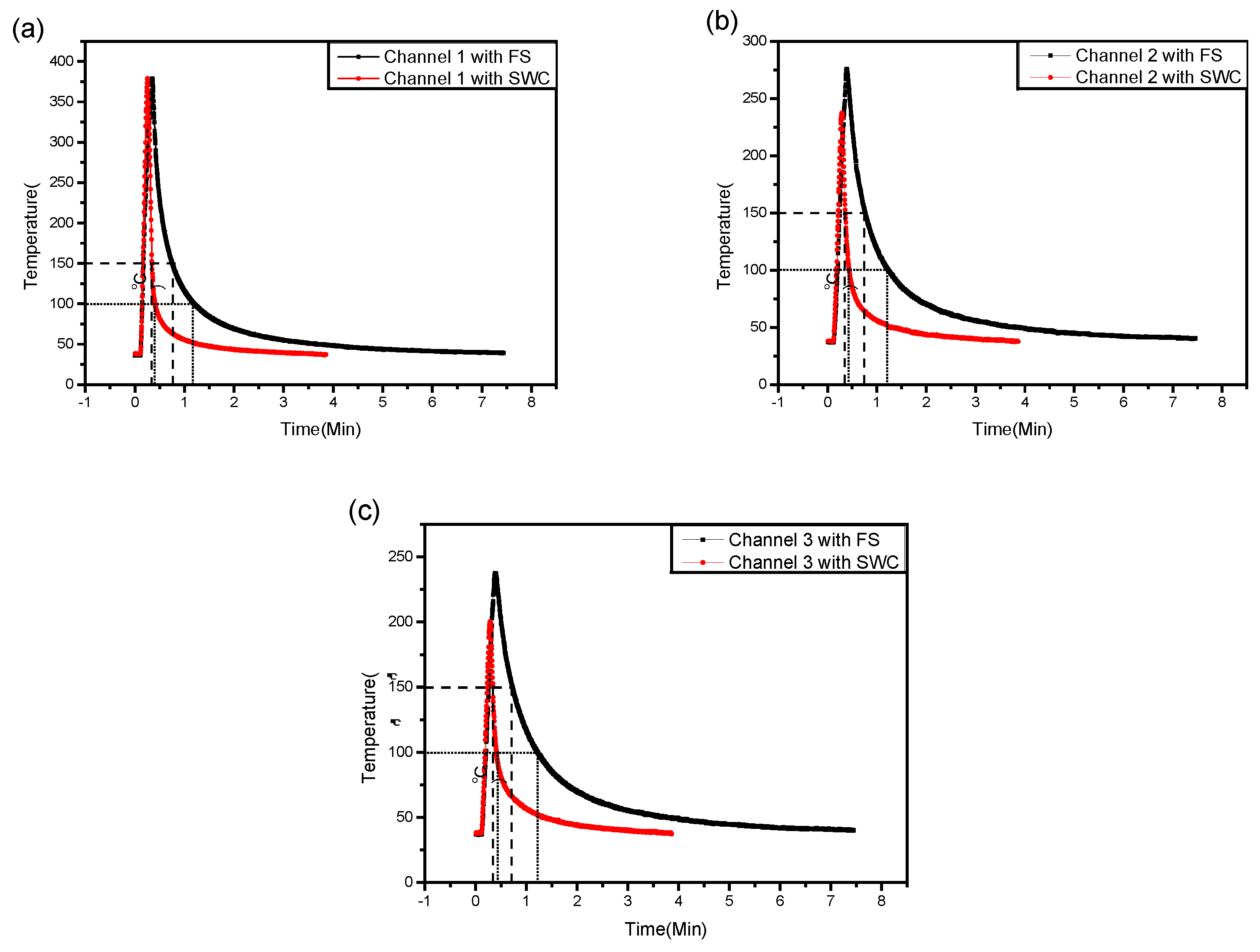
Figure 7.
Macroscopic tensile fracture after (a) flame straightening and (b) synchronous water-cooling.
Figure 7.
Macroscopic tensile fracture after (a) flame straightening and (b) synchronous water-cooling.
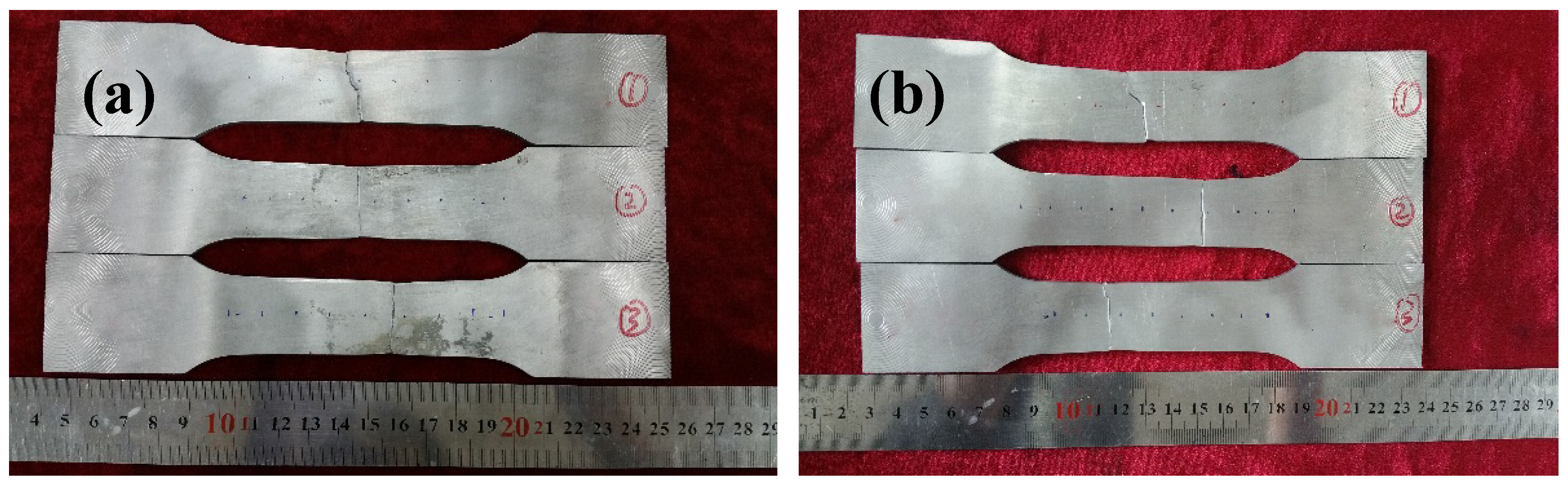
Figure 8.
Fractures of the synchronous water cooling (SWC): (a,b) top, (c,d) bottom.

Figure 9.
Fracture surface of the flame straightening: (a,b) top, (c,d) bottom.

Figure 10.
Microhardness profiles of specimens and base metal.
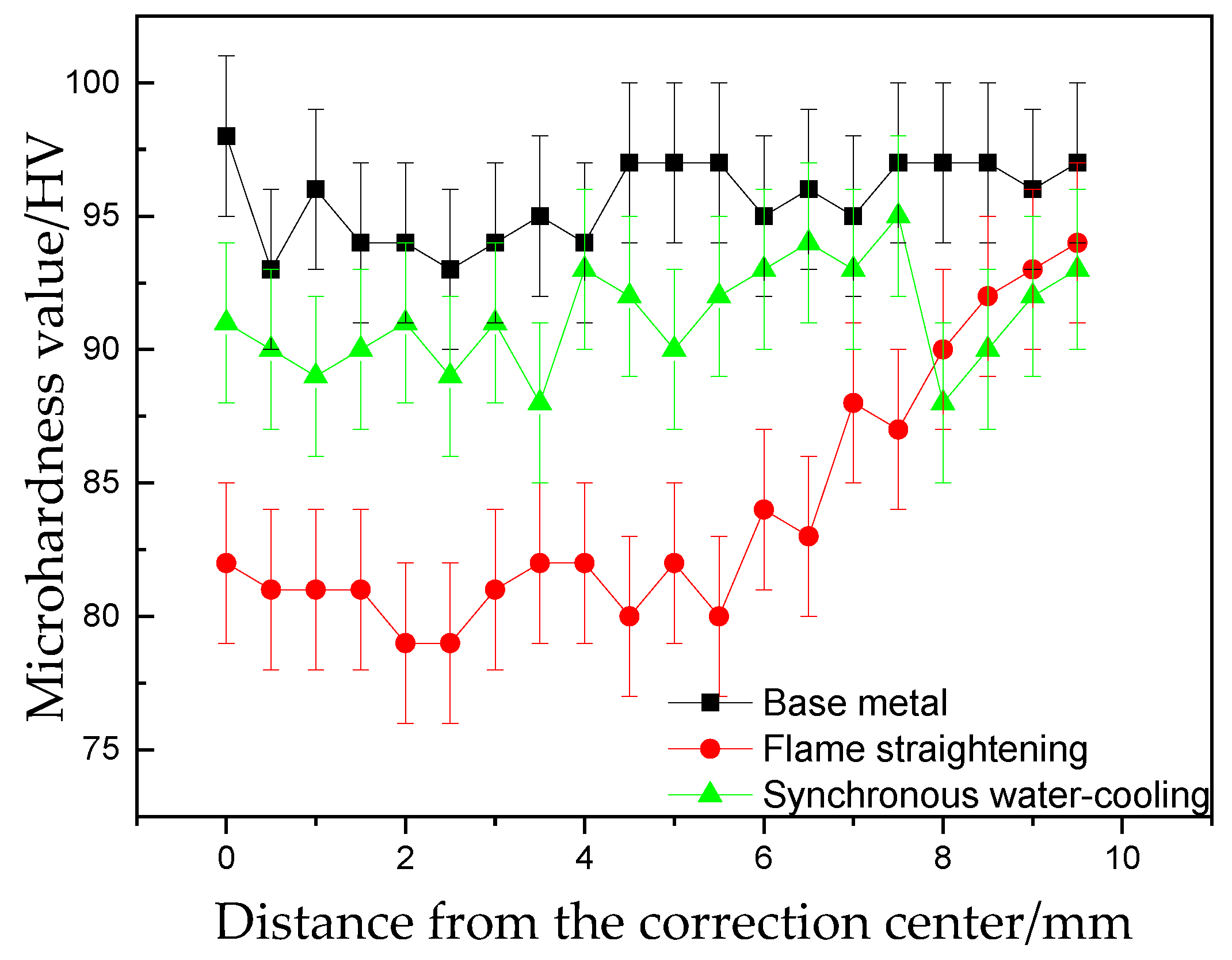
Figure 11.
Sketch map of microstructure.
Figure 12.
Metallograph of synchronous water-cooling: (a–c) under polarized light; (d–f) bright field.
Figure 12.
Metallograph of synchronous water-cooling: (a–c) under polarized light; (d–f) bright field.

Figure 13.
Metallograph of flame straightening: (a–c) under polarized light; (d–f) bright field.
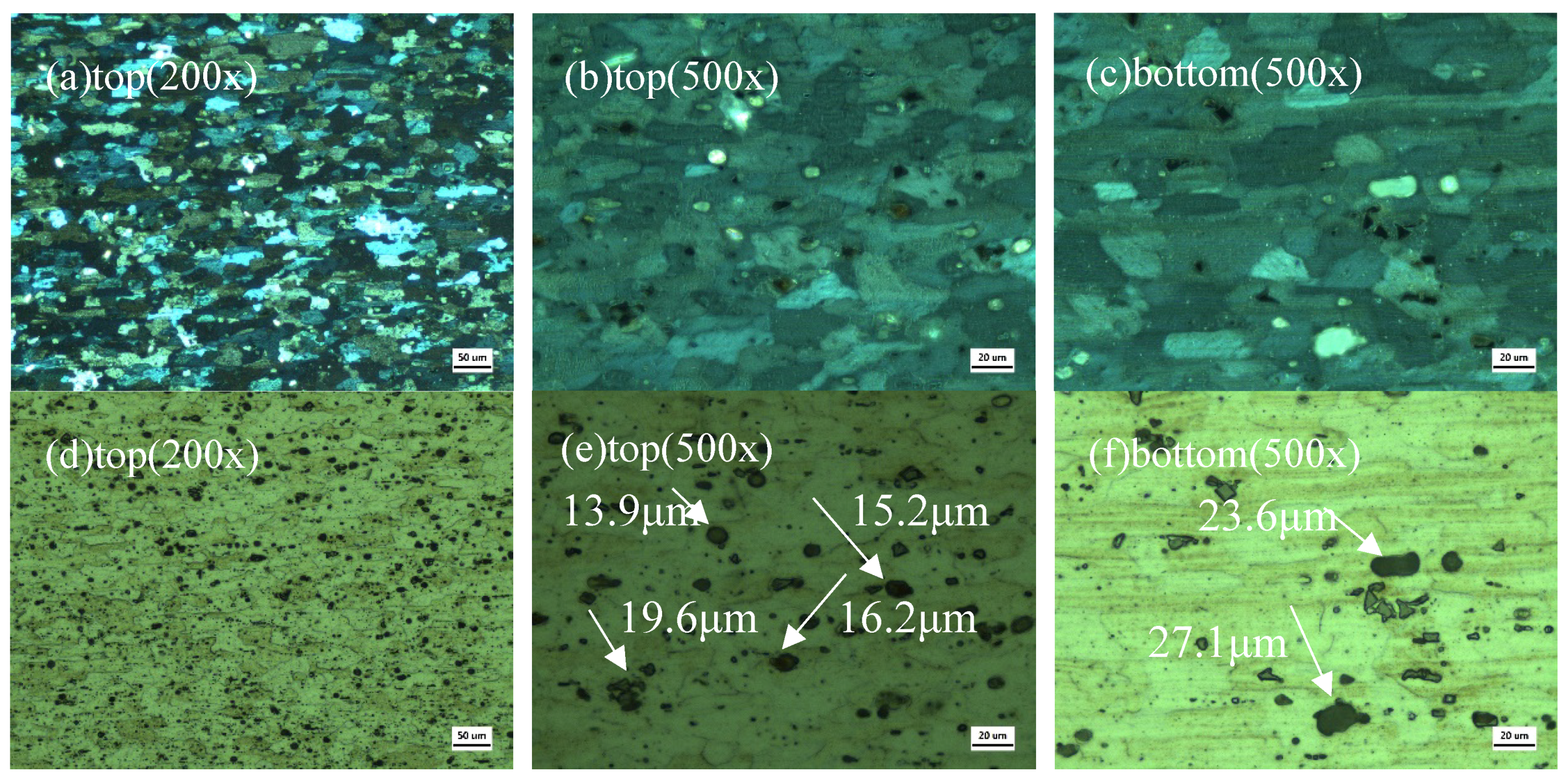
Figure 14.
Scanning electron microscopy (SEM) analysis of precipitates with synchronous water-cooling: (a) measurement position; (b) spectrogram.
Figure 14.
Scanning electron microscopy (SEM) analysis of precipitates with synchronous water-cooling: (a) measurement position; (b) spectrogram.

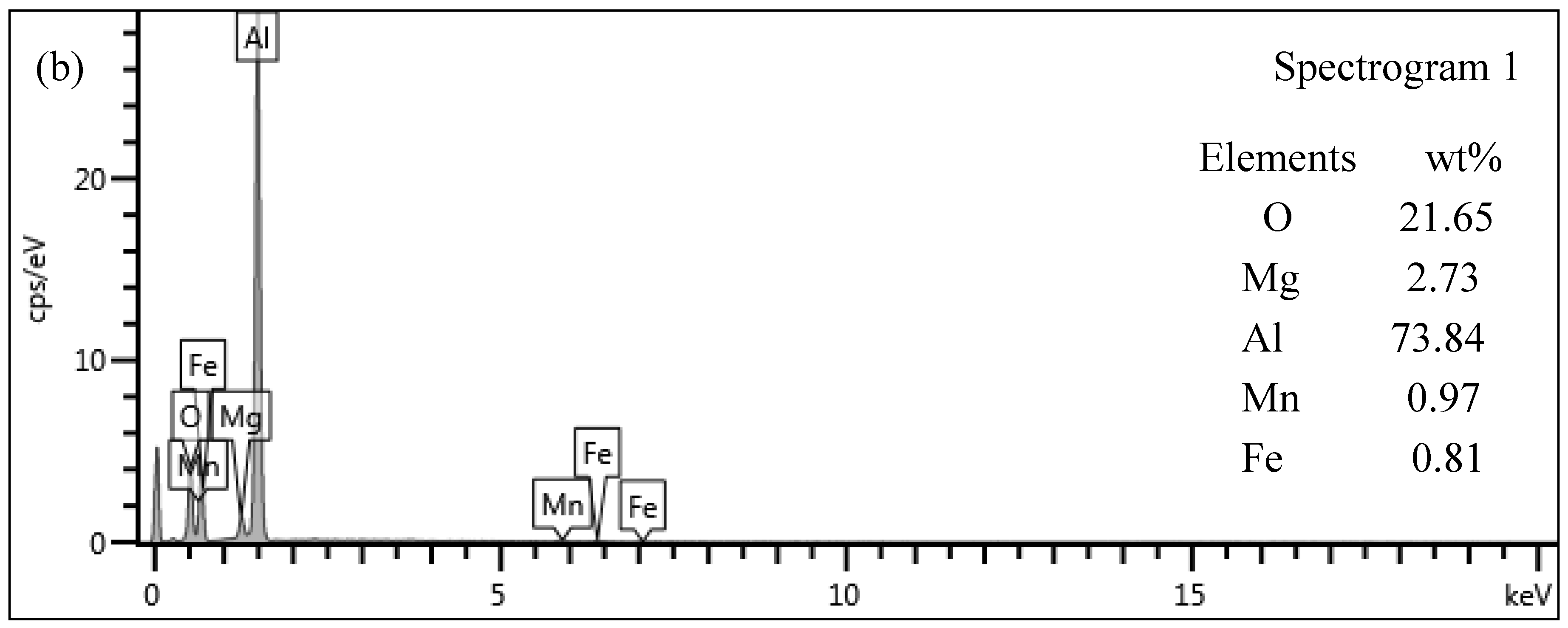
Figure 15.
SEM analysis of precipitates with flame straightening: (a) measurement position; (b) spectrogram.
Figure 15.
SEM analysis of precipitates with flame straightening: (a) measurement position; (b) spectrogram.
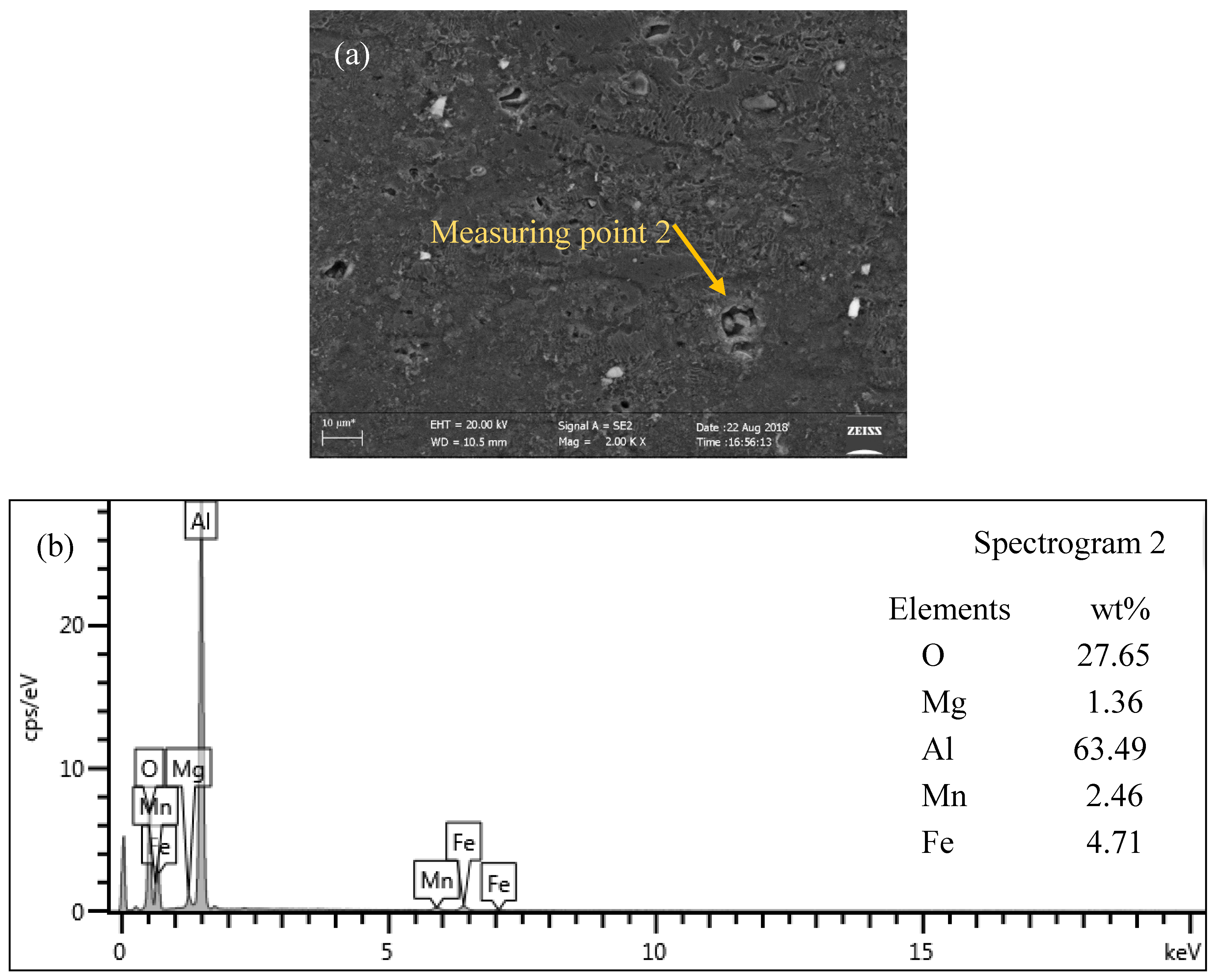
Figure 16.
X-ray diffraction (XRD) patterns of specimens with synchronous water-cooling.

Figure 17.
X-ray diffraction (XRD) patterns of specimens with flame straightening.

Table 1.
Chemical composition of 5083 aluminum alloy element.
| Si | Fe | Cu | Mn | Mg | Cr | Zn | Ti | Al |
|---|---|---|---|---|---|---|---|---|
| 0.4 | 0.1 | 0.1 | 0.4–1.0 | 4.0–4.9 | 4.0–4.9 | 0.25 | 0.15 | 88.2–90.6 |
Table 2.
Tensile test results.
| Tensile Data State | Tensile Strength (Mpa) | 0.2% Yield Strength (Mpa) | Elongation (%) | |
|---|---|---|---|---|
| Base Metal | 1 | 338.7 | 293.4 | 13.9 |
| 2 | 339.5 | 295.0 | 12.0 | |
| 3 | 334.8 | 290.3 | 12.1 | |
| Average | 337.7 | 292.9 | 12.7 | |
| Standard deviation | 2.0 | 2.0 | 0.9 | |
| Synchronous Water-Cooling | 1 | 340.7 | 232.0 | 17.4 |
| 2 | 338.0 | 231.3 | 17.4 | |
| 3 | 335.9 | 232.8 | 17.7 | |
| Average | 338.2 | 232.0 | 17.5 | |
| Standard deviation | 2.0 | 0.6 | 0.1 | |
| Flame Straightening | 1 | 337.2 | 219.3 | 20.7 |
| 2 | 334.1 | 224.4 | 17.3 | |
| 3 | 338.3 | 225.0 | 20.3 | |
| Average | 336.5 | 222.9 | 19.4 | |
| Standard deviation | 1.8 | 2.6 | 1.5 | |
© 2018 by the authors. Licensee MDPI, Basel, Switzerland. This article is an open access article distributed under the terms and conditions of the Creative Commons Attribution (CC BY) license (http://creativecommons.org/licenses/by/4.0/).
Share and Cite
MDPI and ACS Style
Cai, C.; Wang, X.; Liang, Z.; Rao, Y.; Wang, H.; Yan, D. Effects of Water-Cooling on the Mechanical Properties and Microstructure of 5083 Aluminum Alloy during Flame Straightening. Metals 2018, 8, 692. https://doi.org/10.3390/met8090692
AMA Style
Cai C, Wang X, Liang Z, Rao Y, Wang H, Yan D. Effects of Water-Cooling on the Mechanical Properties and Microstructure of 5083 Aluminum Alloy during Flame Straightening. Metals. 2018; 8(9):692. https://doi.org/10.3390/met8090692
Chicago/Turabian StyleCai, Congwei, Xue Wang, Zhimin Liang, Yuzhong Rao, Hongbo Wang, and Dejun Yan. 2018. "Effects of Water-Cooling on the Mechanical Properties and Microstructure of 5083 Aluminum Alloy during Flame Straightening" Metals 8, no. 9: 692. https://doi.org/10.3390/met8090692
Note that from the first issue of 2016, this journal uses article numbers instead of page numbers. See further details here.