
Optimization Design and Performance Analysis of a PM Brushless Rotor Claw Pole Motor with FEM

Abstract
:1. Introduction
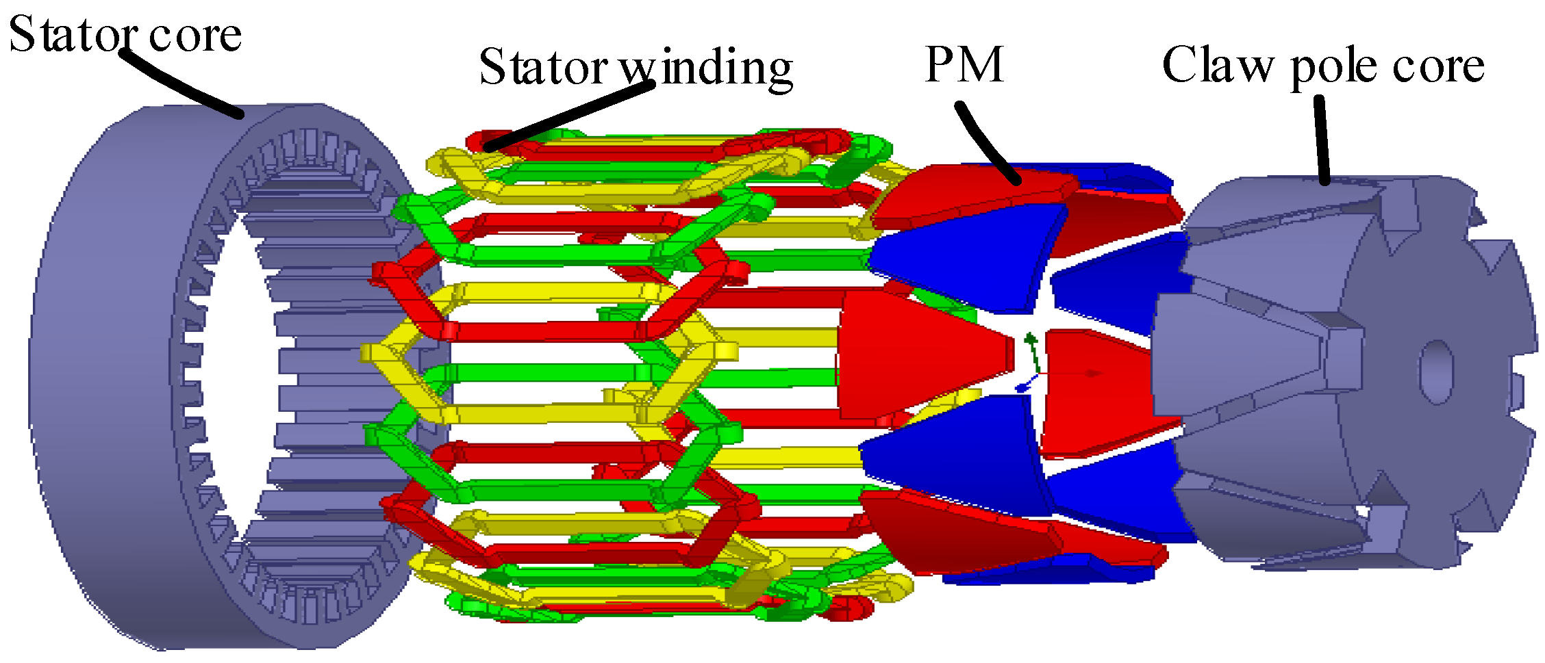
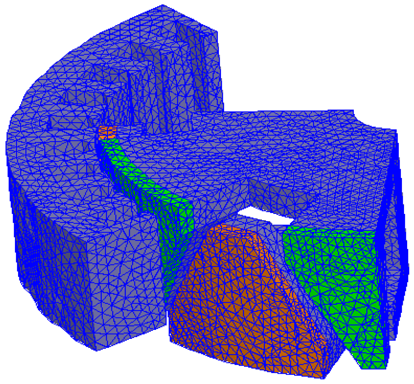
2. 3D FEM Model and Magnetic Circuit of the Proposed CPM
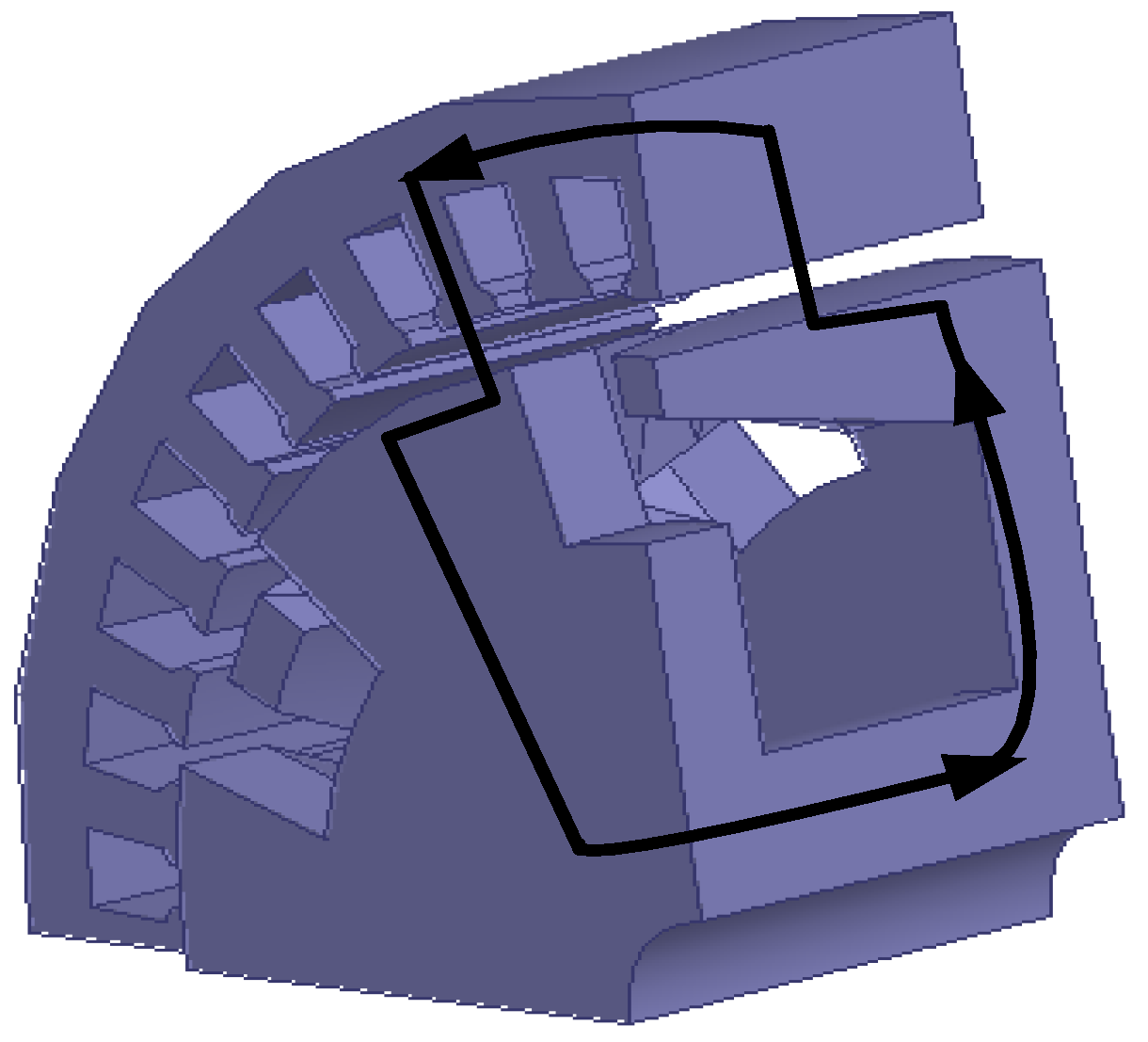
- axially in the magnetic core surrounding the shaft,
- radially in the rotor north plate,
- axially and radially in the rotor north claws,
- radially in the air gap to the stator teeth,
- circumferentially in the lamination following its subdivision into two paths,
- radially down in the air gap through the stator teeth facing the two adjacent rotor south claws,
- radially and axially in the two adjacent rotor south claws,
- radially in the rotor south plate, and
- axially in the magnetic core to close the loop.
3. Output Torque Investigation of the Proposed CPM
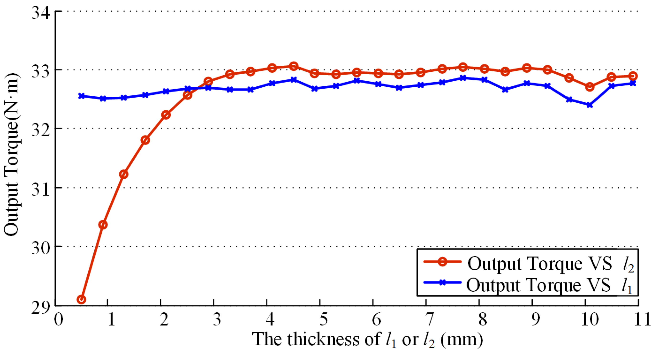
3.1. The Impacts of the Pole Tip Thickness and the Pole Root Thickness
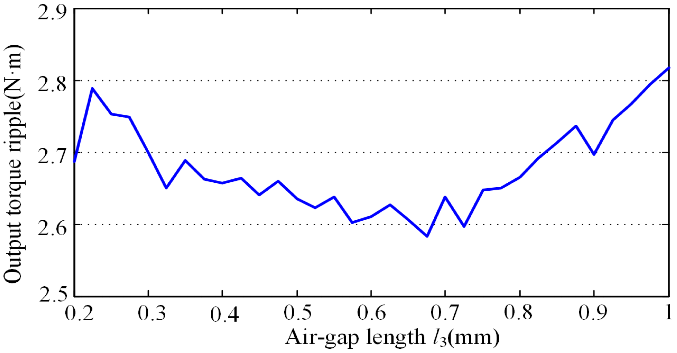
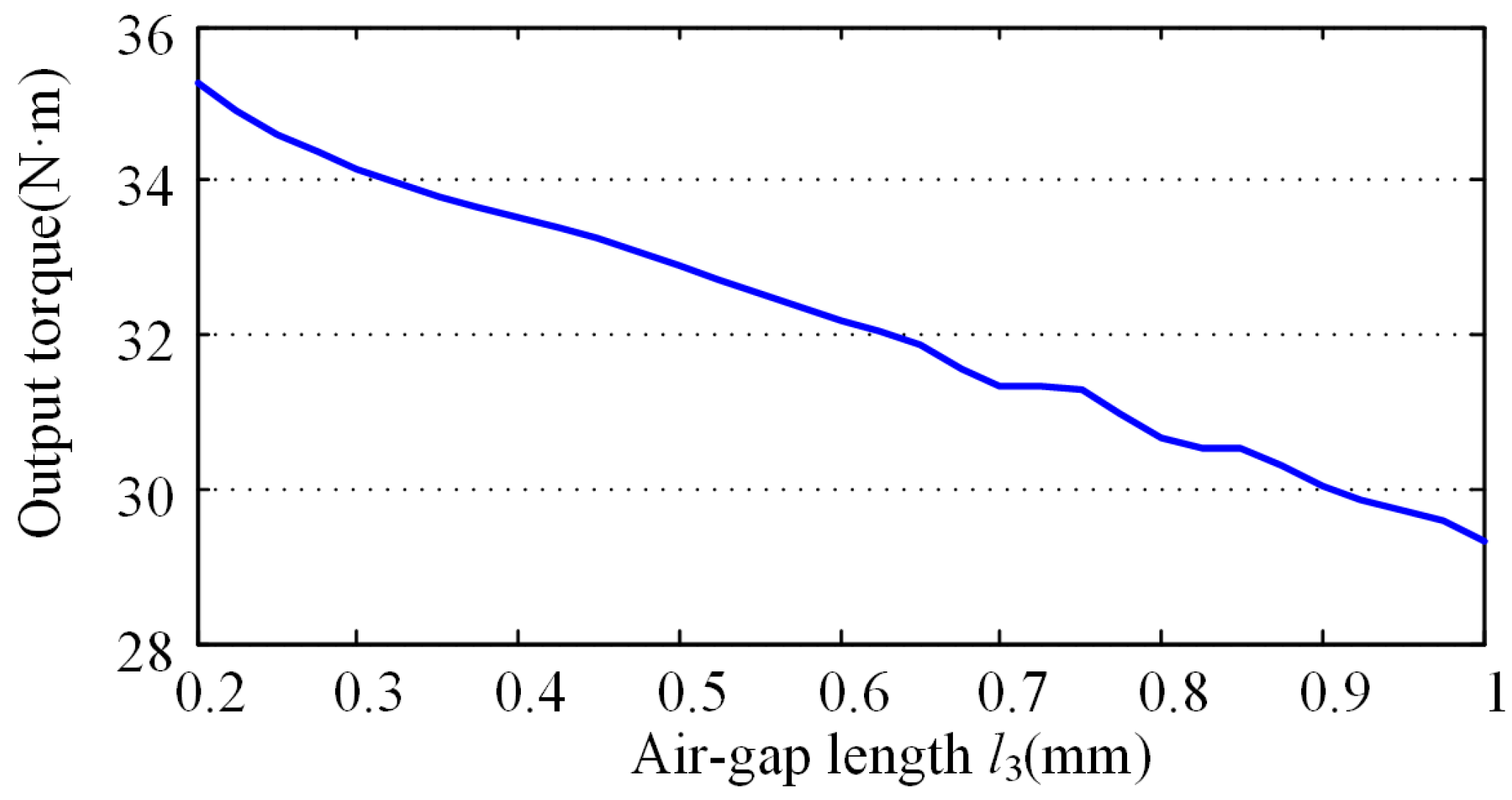
3.2. The Impact of the Air Gap Length
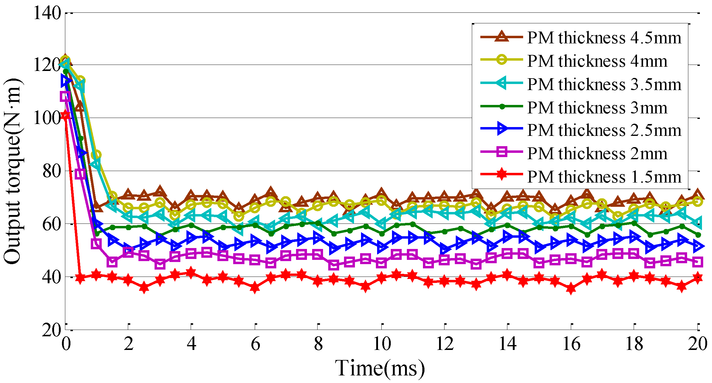
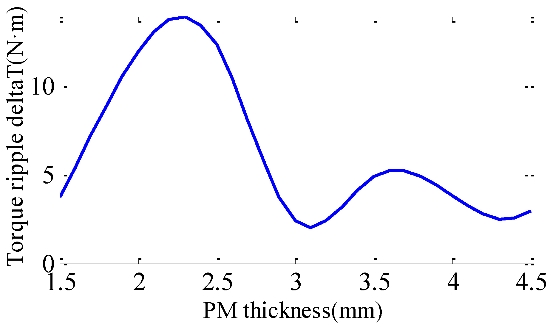
3.3. The Impact of the Thickness of Magnet
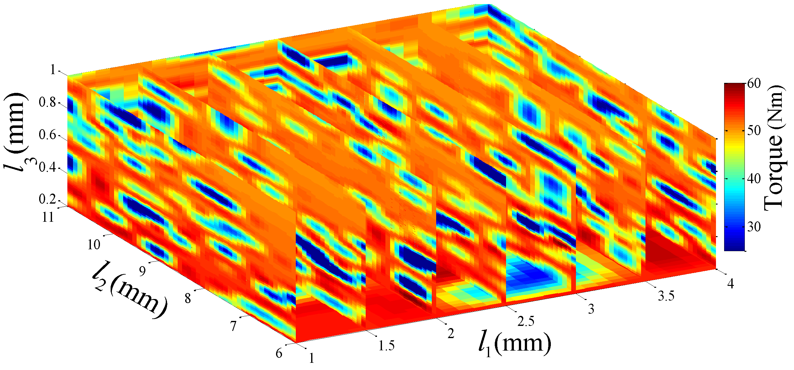
4. Rotor Parameters Optimization of the CPM
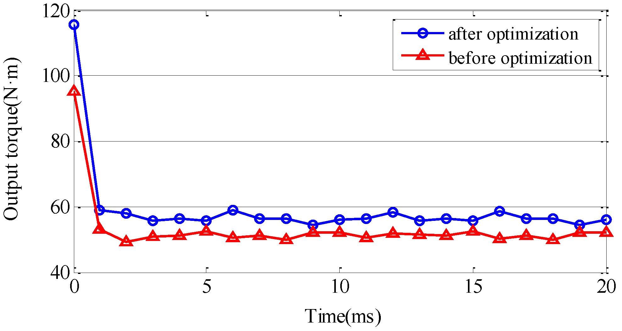
5. Performance Comparison of the Proposed Optimal CPM
6. Conclusions
Acknowledgments
Author Contributions
Conflicts of Interest
References
- Boldea, I.; Tutelea, L.N.; Parsa, L.; Dorrell, D. Automotive electric propulsion systems with reduced or no permanent magnets: an overview. IEEE Trans. Ind. Electron. 2014, 61, 5696–5711. [Google Scholar] [CrossRef]
- Li, W.; Huang, S. Analysis and design of hybrid excitation claw-pole generator. Electr. Power Compon. Syst. 2011, 39, 680–695. [Google Scholar] [CrossRef]
- Li, Y.; Meng, H.; Xia, J.; Liu, J.; Li, T. Study on the structure and electromagnetic of claw pole motor for vehicle. In Proceedings of the IEEE Transportation Electrification Asia-Pacific Conference and Expo, Beijing, China, 31 August–3 September 2014.
- Liu, C.; Zhu, J.; Wang, Y.; Guo, Y.; Lei, G. Comparison of claw pole machines with different rotor structures. In Proceedings of the IEEE Transactions on Magnetics Conference, Beijing, China, 11–15 May 2015.
- Deodhar, R.P.; Pride, A.; Bremner, J.J. Design method and experimental verification of a novel technique for torque ripple reduction in stator claw-pole PM machines. IEEE Trans. Ind. Appl. 2015, 51, 3743–3750. [Google Scholar] [CrossRef]
- Mönnich, O.; Daweke, R.D.; Lehr, H. Miniaturized claw-pole generators and motors with high power density. In Proceedings of the International Conference on Optimization of Electrical and Electronic Equipment, Brasov, Romania, 22–24 May 2014.
- Tong, C.; Zheng, P.; Wu, Q.; Bai, J.; Zhao, Q. A brushless claw pole double-rotor machine for power-split hybrid electric vehicles. IEEE Trans. Ind. Electron. 2014, 61, 4295–4305. [Google Scholar] [CrossRef]
- Rebhi, R.; Ibala, A.; Masmoudi, A. On the comparison between the stator and rotor-excited claw pole alternators. Electr. Power Compon. Syst. 2012, 40, 1019–1029. [Google Scholar] [CrossRef]
- Shen, Y.; Zhu, Z.; Chen, J.; Deodhar, R.P.; Pride, A. Analytical modeling of claw-pole stator SPM brushless machine having SMC stator core. IEEE Trans. Magn. 2013, 49, 3830–3833. [Google Scholar] [CrossRef]
- Guo, Y.; Zhu, J.; Dorrell, D.G. Design and analysis of a claw pole permanent magnet motor with molded soft magnetic composite core. IEEE Trans. Magn. 2009, 45, 4582–4585. [Google Scholar]
- Dou, Y.; Guo, Y.; Zhu, J.; Lu, H. Effect of armature reaction of a permanent-magnet claw pole SMC motor. IEEE Trans. Magn. 2007, 43, 2651–2653. [Google Scholar] [CrossRef]
- Ho, S.L.; Yang, Y.S.; Ni, G.Z.; Wong, H.C. A response surface methodology based on improved compactly supported radial basis function and its application to rapid optimizations of electromagnetic devices. IEEE Trans. Magn. 2005, 41, 2111–2117. [Google Scholar] [CrossRef]
- Clerc, M.; Kennedy, J. The particle swarm—Explosion, stability, and convergence in a multi-dimensional complex space. IEEE Trans. Evol. Comput. 2002, 6, 58–73. [Google Scholar]
- Hasanien, H.M. Particle swarm design optimization of transverse flux linear motor for weight reduction and improvement of thrust force. IEEE Trans. Ind. Electron. 2011, 58, 4048–4056. [Google Scholar] [CrossRef]
- Lei, G.; Zhu, J.; Guo, Y.; Shao, K.; Xu, W. Multi-objective sequential design optimization of PM-SMC motors for six sigma quality manufacturing. IEEE Trans. Magn. 2014, 50, 1–4. [Google Scholar] [CrossRef]
- Saavedra, H.; Riba, J.-R.; Romeral, L. Multi-objective Optimal Design of a Five-Phase Fault-Tolerant Axial Flux PM Motor. Adv. Electr. Comput. Eng. 2015, 15, 69–76. [Google Scholar] [CrossRef] [Green Version]
- Santiago, J.D.; Bernhoff, H. Calculation of Tooth Ripple Losses in Solid Poles. Electr. Power Compon. Syst. 2015, 43, 245–251. [Google Scholar] [CrossRef]


| Rated power (kW) | 3 |
| Input current (A) | 100 |
| Speed (RPM) | 500 |
| Magnet type | NdFe35 |
| Output torque (N·m) | 56.54 |
| Frequency (Hz) | 50 |
| Poles | 12 |
| Number of stator slots | 36 |
| Parameter | SMC | DW360 |
|---|---|---|
| Kh | 657.3 | 168 |
| Ke | 0 | 0 |
| Kc | 0.09 | 0.8 |
| Output torque of full-load (N·m) | 56.54 | 51.3 |
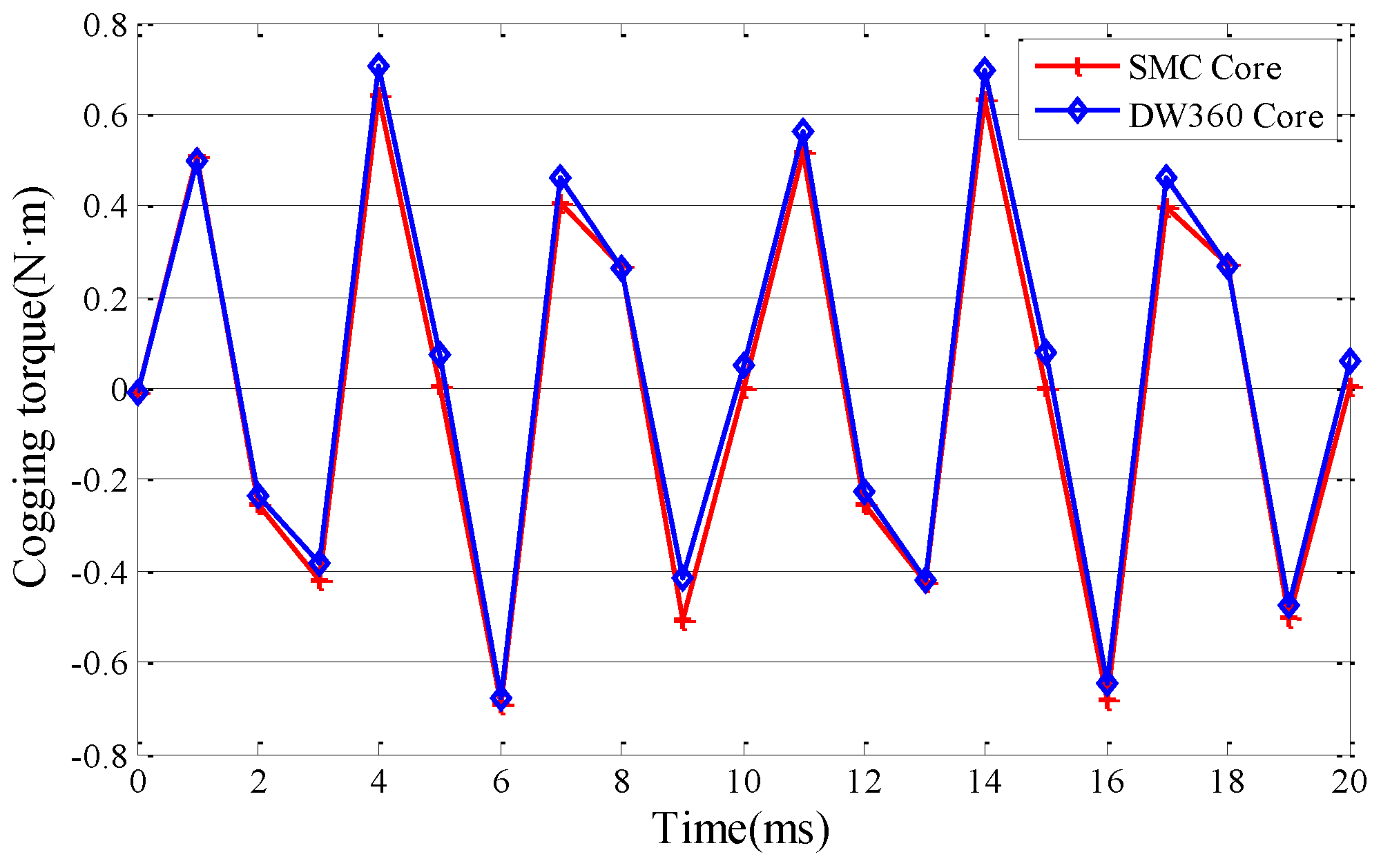
| Average cogging torque (N·m) | 0.64 | 0.71 |
| Output power (kW) | 2.96 | 2.68 |
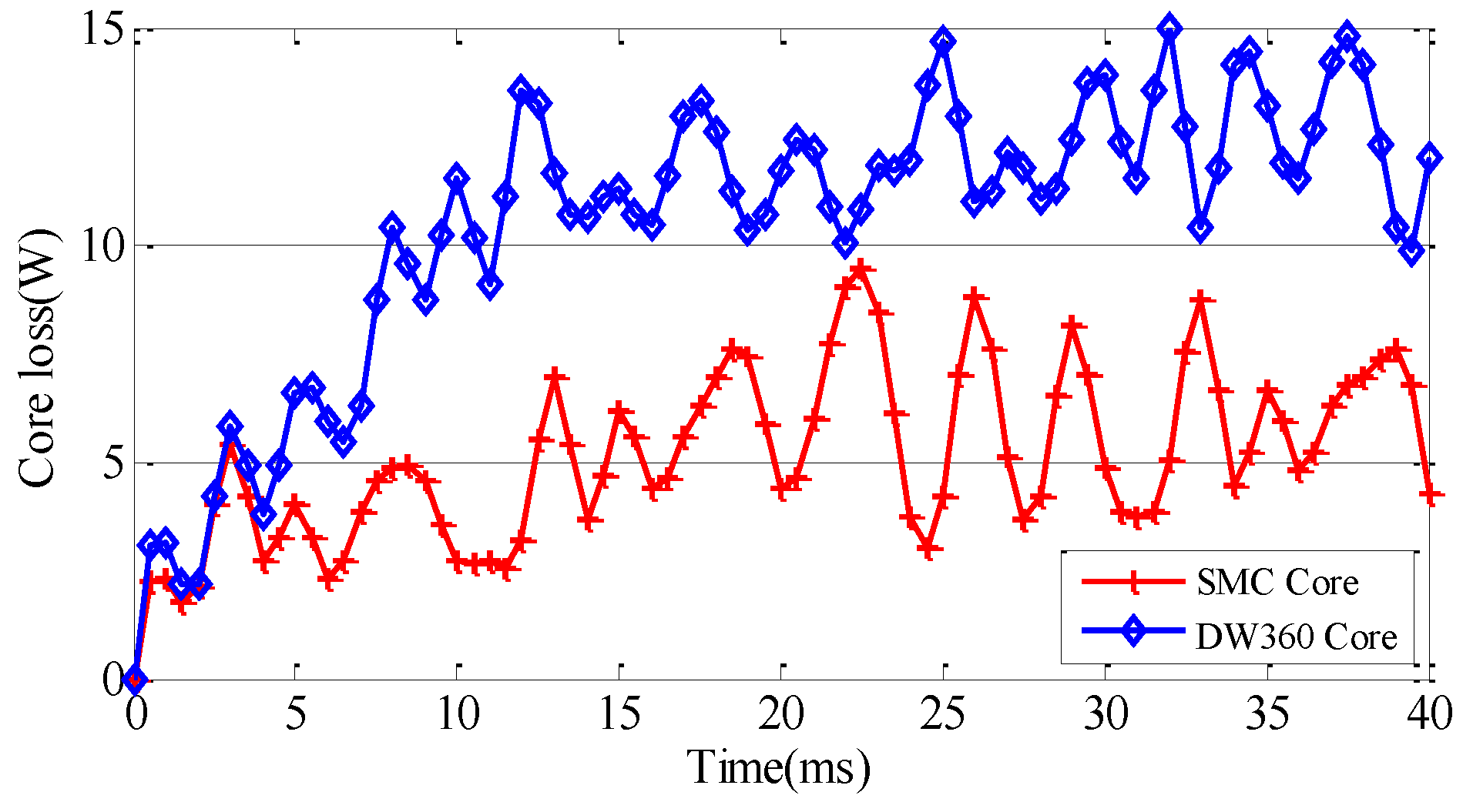
| Core loss (W) | 6 | 12.5 |
| Copper loss (W) | 24.57 | 24.57 |
| PM Loss (W) | 1.6 | 1.6 |
| Efficiency | 98.92% | 98.58% |
© 2016 by the authors; licensee MDPI, Basel, Switzerland. This article is an open access article distributed under the terms and conditions of the Creative Commons Attribution (CC-BY) license (http://creativecommons.org/licenses/by/4.0/).
Share and Cite
Zhang, Z.; Liu, H.; Song, T. Optimization Design and Performance Analysis of a PM Brushless Rotor Claw Pole Motor with FEM. Machines 2016, 4, 15. https://doi.org/10.3390/machines4030015
Zhang Z, Liu H, Song T. Optimization Design and Performance Analysis of a PM Brushless Rotor Claw Pole Motor with FEM. Machines. 2016; 4(3):15. https://doi.org/10.3390/machines4030015
Chicago/Turabian StyleZhang, Zhenyang, Huijuan Liu, and Tengfei Song. 2016. "Optimization Design and Performance Analysis of a PM Brushless Rotor Claw Pole Motor with FEM" Machines 4, no. 3: 15. https://doi.org/10.3390/machines4030015