1. Introduction
Solar cover glasses for solar thermal applications prevent convection and radiation losses of the solar collector, and are used for thermal insulation of the solar receiver [
1]. A drawback of any cover material is the loss of the incident sunlight by reflection at the surfaces of the cover sheet. Therefore, antireflective (AR) coatings (e.g., from porous silica) are applied to minimize reflection losses (e.g., see [
2,
3,
4,
5]). However, a decrease in solar transmittance, which means a decreased efficiency of the solar collector, is also caused by contaminants like volatile organic carbons or biofouling products at the surface of the cover glasses. The most investigated photocatalyst, which can oxidize and decompose organic and inorganic contaminants, is titania in the anatase modification. For solar applications, several multilayer systems with antireflective (AR) and antifouling (AF) properties, containing titania, have been investigated [
6,
7,
8,
9,
10,
11,
12], and a bifunctional AR and AF single layer from dispersed TiO
2 in a silica matrix has also been studied [
13].
Also, ceria (CeO
2) turned out to be a promising oxide component for a combined AR and AF function since pure ceria is an n-type semiconductor with oxygen-deficient structure balancing the charge between Ce
3+ and Ce
4+. Labile lattice oxygen is available to catalyze oxidation processes and, thus, thin films [
14,
15,
16], nanoparticles [
17,
18], nanosheets [
19,
20], hollow fibers [
21], and nanorods [
22] of pure and doped ceria are prepared with catalytic properties. With respect to optical properties, ceria nanoparticles, like titania nanoparticles, are highly refractive, and therefore they have been used to tune the refractive index of polymer thin films up to 1.95 [
23].
Coatings from ceria in combination with silica are, so far, only developed as corrosion inhibitors for metals such as alumina alloy [
24] and zinc [
25], and as a barrier preventing sodium diffusion (from soda-lime substrate glasses) into functional coatings [
26]. The combination of the photocatalytic activity of ceria with the antireflectivity of a porous silica layer for solar applications is, to the best of our knowledge, not investigated yet.
This study is further motivated by the specific crystallization of amorphous ceria in thin films. Firstly, amorphous ceria crystallizes in the form of a single high-temperature-stable cubic polymorph. Size- and temperature-dependent transformation kinetics from low- to high-temperature polymorphs, such as observed in titania [
6,
7,
8,
9,
10,
11,
12,
13,
14,
15,
16,
17,
18,
19,
20,
21,
22,
23,
24,
25,
26,
27], are lacking. Secondly, the crystallization of ceria prepared by precipitation-based film processing is known to undergo a double-stage transformation process, showing biphasic amorphous–crystalline nanostructures of isolated grains at the first stage [
28,
29]. Solvent molecules are found to slow down the transition to the second stage, while Oswald ripening is observed after establishing cluster contacts [
30]. It is expected that mixing ceria sols with silica sols will further stabilize an isolated ceria grain structure in the coating. Finally, ceria is known to act as a photocatalyst under visible light radiation [
18,
21], which can enhance self-cleaning properties of solar cover glasses if added to AR coating materials.
We report, therefore, a compositional study on the effect of ceria additions to a sol–gel-derived porous silica coating on glass. We will show that ceria crystallizes unexpectedly at low temperatures (140 °C) at the interface and surface of the coating, which leads to a beneficial three-layered mesostructure and a combined AR and AF function of single coat.
2. Results
Coated solar glasses (soda-lime silicate), as prepared by dipping in Ce-bearing silica sol, were characterized by various optical and microstructural methods. UV–Vis–NIR transmittance of the ceria–silica coats was measured to explore their AR function, but also UV-A radiation was used to test the degradation capacity of a model contaminant (stearic acid) at their surface. Both properties could be traced to the structure of the coatings, which was studied by grazing incidence X-ray diffraction (GIXRD) and secondary neutral mass spectrometry (SMNS). Six different coatings were prepared and, according to their ceria molar fraction of 0, 5%, 10%, 17%, 25%, and 33.3%, were identified as 0–100, 5–95, 10–90, 17–83, 25–75, and 33–67, respectively. Standard curing of the layer was done at 350 °C for 60 min. It is shown that self-assembly of ceria crystals at the interference and surface of the 17–83 coating contributes to a gain in solar transmittance of 3.2% and degrades the applied stearic acid film under UV-A radiation by half in about 30 min.
2.1. Transmittance by UV–Vis–NIR Spectroscopy
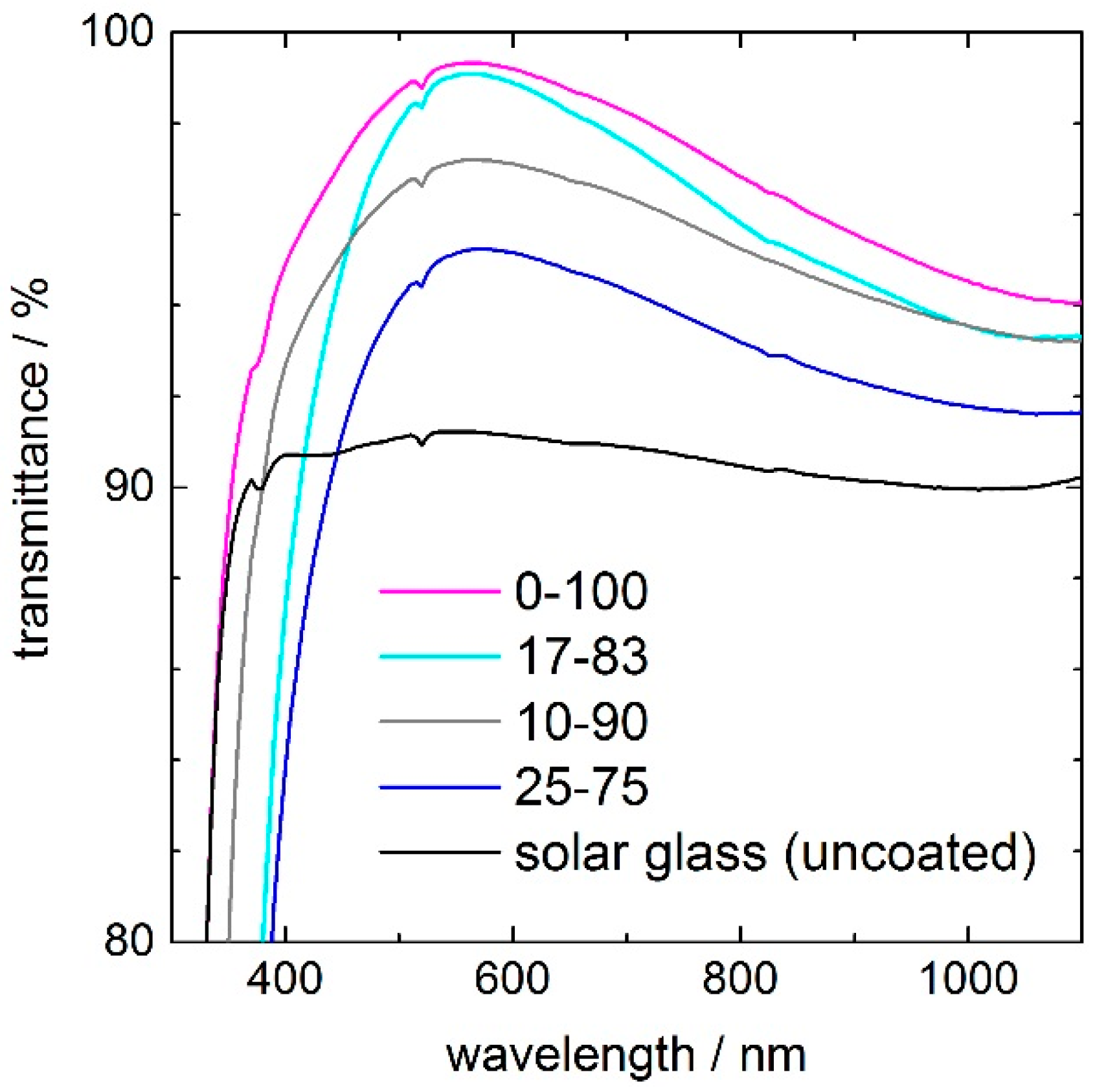
The transmittance spectra of silica coatings with ceria concentrations of 10, 17, and 25 mol %, compared to uncoated solar glass, are shown in
Figure 1. All coatings have their transmittance maximum at around λ = 550 nm, which means that the refractive index
n and coating thickness
d met the phase condition
n ×
d = λ/4 for this wavelength. The pure silica coating 0–100 increases the maximum transmittance of the solar glass from 91% up to more than 99% at 550 nm, which indicates that the porosity of the coating is approximately 38% [
5]. Increasing ceria contents from 5% to 25% led to a decreasing transmittance maximum, from 99% to 95%. A second effect of ceria is a red-shift of the UV-edge due to its bandgap energy of 3.1 eV [
15]. Taking the 25–75 coating as an example and the wavelength of 50% transmittance, the UV-edge is shifted by 30 nm, from 310 to 340 nm. Depending on ceria concentration, the UV-transmittance (weighted air mass (AM) 1.5 average value in the UV-A and UV-B range from 280 to 380 nm) reduces drastically (
Table 1). The UV-transmittance of the pure silica coating 0–100 is decreased from 84% to 73% for the 10–90 coating and to 67% for the 17–83 coating. Because the UV transmittance of Ce-containing films is very sensitive to the coating thickness, the uncertainty in the measurement is increasing with increasing ceria content to about ±5% for the 33–67 coating. The solar transmittance (weighted AM 1.5 average value in the wavelength range from 300 to 2500 nm) decreases from 95.7% for the pure silica coating to 93.7% for the 17–83 coating, whereas the uncoated solar glass has a solar transmittance of 90.3%. The individual transmittance values of the coatings and the uncoated solar glass are listed in
Table 1.
2.2. Crystalline Nature by Grazing Incidence X-ray Diffraction (GIXRD)
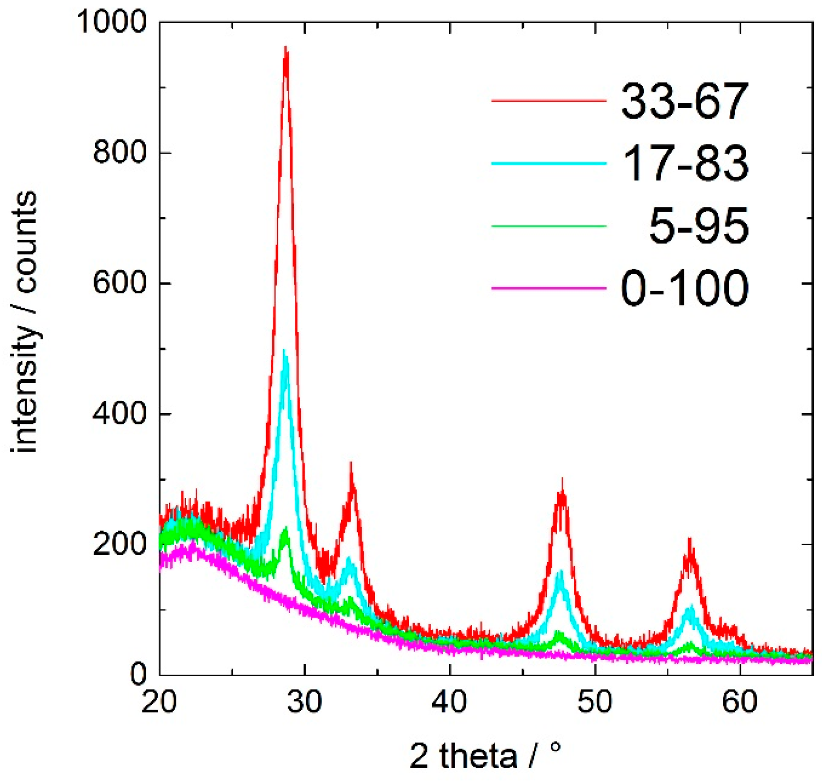
Figure 2 shows the X-ray-diffraction pattern of the ceria-containing silica coatings after curing at 350 °C for 60 min. The peaks corresponding to the (111), (200), (220), and (311) planes of fluorite structured cubic ceria at approximately 28°, 33°, 47°, and 57° 2θ (PDF card 98-019-2224) are clearly identified. The fraction of crystalline ceria is increasing with increasing cerium content in the coating.
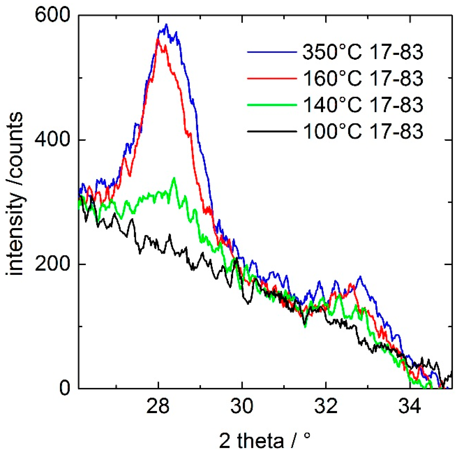
In order to reveal the onset of the ceria crystallization, a freshly dip-coated, unheated 17–83 coating was studied in situ in a high-temperature chamber by GIXRD with a heating rate of 10 K/min.
Figure 3 shows that the coating heated up to 100 °C remains amorphous, while that treated at higher temperatures results in the presence of cubic ceria crystals. The onset of crystallization is detected for a thermal treatment at 140 °C, and crystallization of the ceria fraction seems to be completed, as inspected from the peak heights, at 160 °C. Using Scherrer equation and the full width at half-maximum of the (111) peak of
Figure 3, the size of the crystal domains were estimated to be ca. 5.5 nm (±0.5 nm) for 160 and 350 °C.
2.3. Chemical Depth Profiling by Secondary Neutral Mass Spectrometry (SNMS)
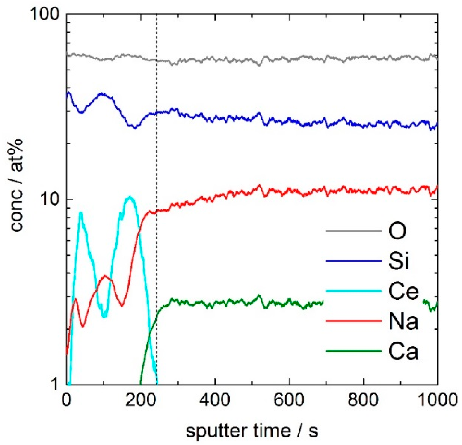
Figure 4 shows the concentration depth profiles of oxygen (O), silicon (Si), cerium (Ce), sodium (Na), and calcium (Ca) of the 17–83 coating. Whereas the sputter rate for the glass substrate is 0.3 nm·s
−1, the sputter rate for the porous layer is 0.5 nm·s
−1. After a sputter time of 240 s, corresponding to 120 nm, the coating is removed. In order to reveal details of the minor fraction cerium, the concentration axis of
Figure 4 is shown in logarithmic scales. For the depth profile of Ce, a double peak in the coating with maximum intensities at 50 s (25 nm) and 170 s (85 nm) and a minimum intensity at 110 s (55 nm) is evident. At the depth of the minimum of the Ce-double peak, silicon shows a maximum in the intensity, which indicates a CeO
2/SiO
2/CeO
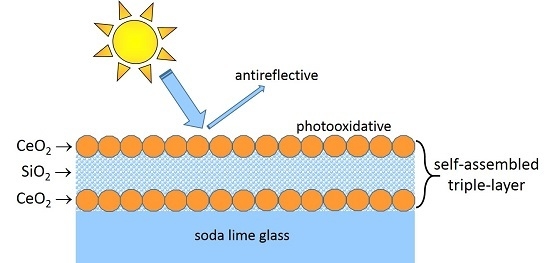
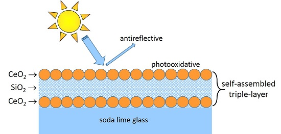
2-rich layered structure of the coating after curing at 350 °C for 60 min. This triple-layer structure consists of two ceria-rich layers, one at the coating/air interface, the other at the coating/glass interface, and a silica-rich layer between.
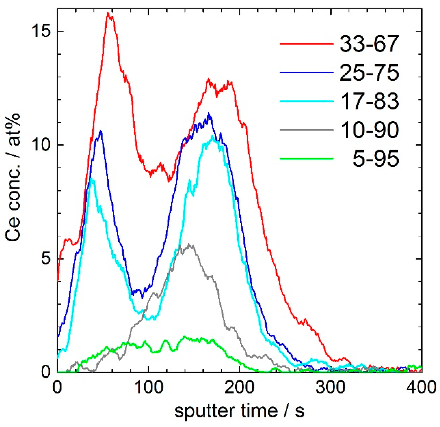
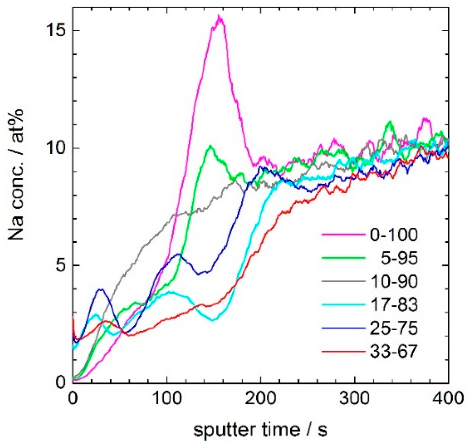
Figure 5 shows the evolution of the Ce-depth profile with increasing ceria concentration of the 120 nm porous silica coating. Whereas in the 5–95 coating a Ce concentration of less than 2 atom % is nearly homogeneously distributed in the whole layer, the 10–90 coating shows an enrichment up to 6 atom % at the interface to the glass substrate. In the more Ce-rich coatings, a Ce double-peak is built up to 10 and 12 atom % in the 17–83 and 25–75 coating. For the coating with 33 mol % CeO
2, the concentration of Ce is up to 16 atom %, but the double peak seems to be less separated. Not shown, but also measured, was a 250 nm porous silica layer with 17 mol % CeO
2, where the double peak was clearly pronounced with minimum and maximum Ce concentrations of 1 and 10 atom %. Furthermore, it can be noted that the height ratio of the two Ce maxima is shifting, depending on the ceria concentration.
Figure 6 shows that the Na hump located at the second Ce maximum (close to 170 s sputter time, i.e., at 85 nm depth) is vanishing, and the average sodium concentration in the layer is decreasing with increasing ceria concentration of the coating. In the porous silica layer without ceria, the Na-enrichment is up to 16 atom %, in the 5–95 coating up to 10 atom %, and in the 17–83 coating Na shows a relative smooth depth dependence with a maximum value of less than 4 atom %. This development can be explained by the assumption that the diffusion of sodium ions from the glass substrate into the layer is blocked by ceria.
2.4. Nanostructure by Field-Emission Scanning Electron Microscopy (FESEM)
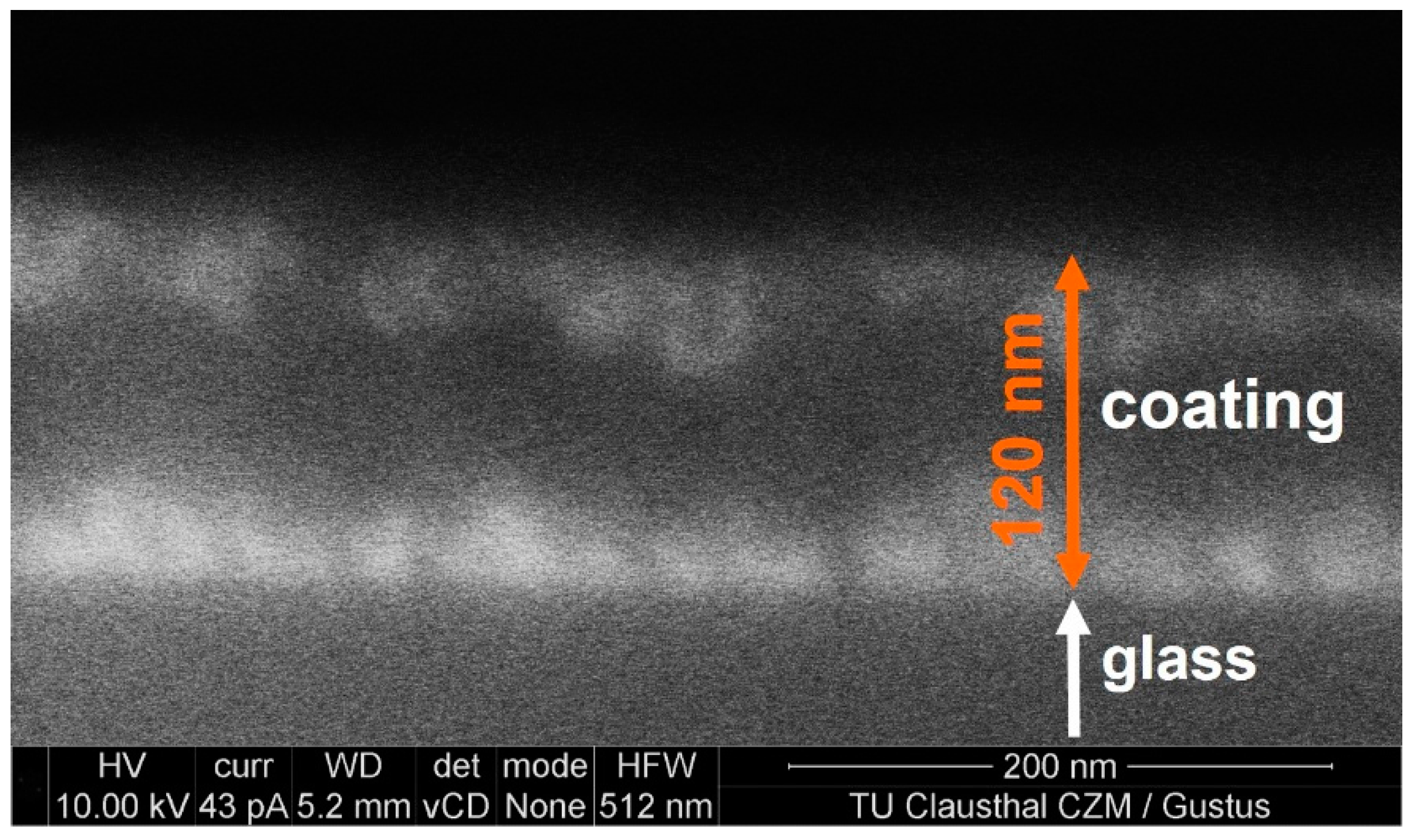
Figure 7 shows a micrograph (backscattered electrons) of the surface of a fractured cross-section of the 17–83 coating. The chemical contrast between the lighter Si atoms (dark) and the heavier Ce atoms (bright) is clearly indicated in the backscattering mode. The FESEM image confirms the sequence of a CeO
2/SiO
2/CeO
2-rich layered structure of the coating with ceria crystals at the interfaces to the air and to the glass substrate, as proved by the SNMS and GIXRD data. The size of the ceria crystals is estimated from the bright regions of
Figure 7 to be in the range from 20 to 40 nm.
2.5. Photocatalytic Activity by Degradation of a Stearic Acid Film
Figure 8 and
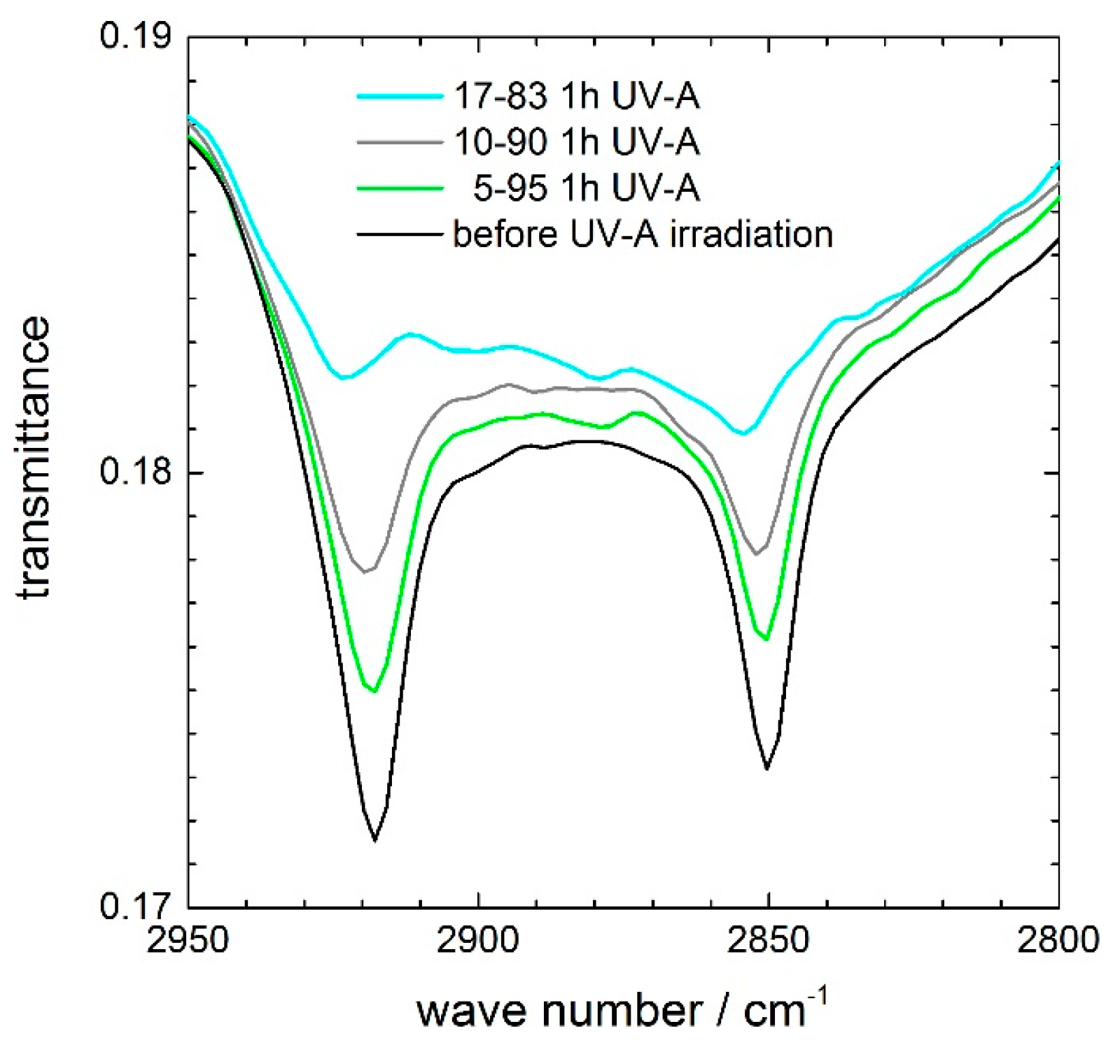
Figure 9 show the characteristic absorption bands of the CH
2-stretching modes at 2853 and 2923 cm
−1 of a stearic acid film on a ceria-containing coating before and after UV-A irradiation.
Figure 8 compares the stearic acid degradation during 1 h of UV-A irradiation of the 5–95, 10–90, and 17–83 coating. An increase in the photocatalytic activity with increasing ceria content is evident. In particular, the 17–83 coating nearly completely degrades the stearic acid film during 1 h of UV-A irradiation, while the 10–90 coating reduces the IR peaks to approximately half. For the 5–95 coating, the stearic acid degradation is lower, but clearly visible if one compares the bands with their heights before UV-A irradiation.
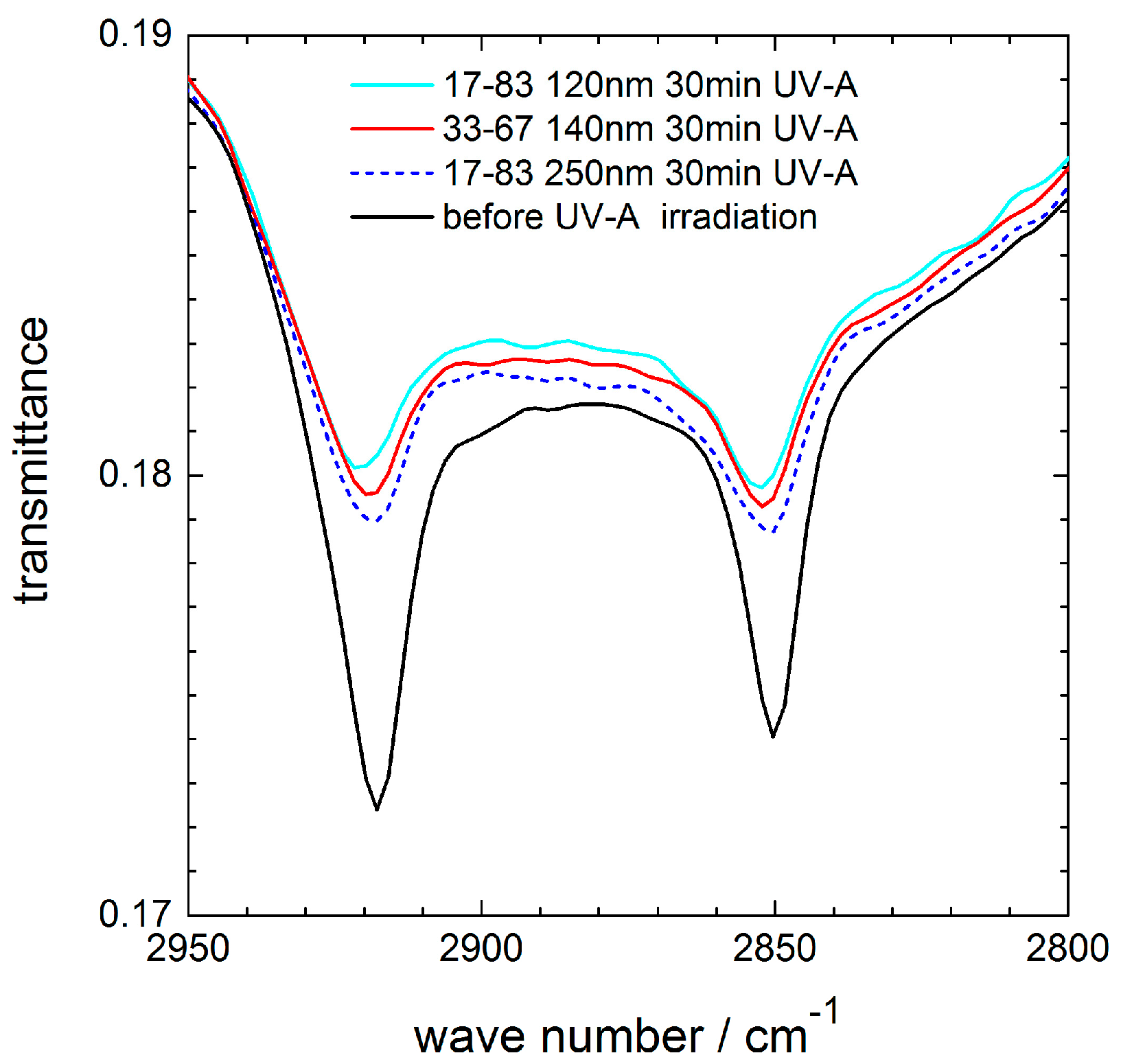
For coatings with 25 (not shown) and 33 mol % ceria, the same photocatalytic activity was found as for the 17–83 coating. Also, an increased thickness (250 nm) of the 17–83 coating did not result in an increased stearic acid degradation. These effects are displayed in
Figure 9, which shows exemplarily the characteristic absorption bands of the CH
2-stretching modes before and after 30 min UV-A irradiation for 120 nm and 140 nm thick coatings containing 17 and 33 mol % ceria, respectively, and for a 250 nm thick coating with 17 mol % ceria. Within the accuracy of the measurements, no differences in the photocatalytic activity were detected. For comparison, the photocatalytic activity of a pure silica coating 0–100 (not shown) was also investigated, but no decrease of the stearic acid absorption bands was measured within 30 or 60 min of UV-A irradiation.
3. Discussion
The most striking feature of this study is the self-assembled ceria crystallization at the interfaces, which resulted in a three-layered architecture of the coating. It is known from precipitation-based film processing that ceria tends to show nanostructures of isolated grains [
28,
29]. Segregation of ceria clusters are stabilized by solvent molecules, which hinder cluster contacts and further grain growth by Oswald ripening [
30]. If one assumes that in the prepared cerium-bearing suspensions hydrated CeO
2- and SiO
2-colloids are present, a “convective assembly” during withdrawal of the glass substrate and evaporation of the solvent might be possible [
31]. In particular, a two-step mechanism is reported in which colloidal aggregation is first initiated by attractive capillary forces, which are balanced in the solvent meniscus between the ordering nanoparticles at the drying front. Secondly, evaporation of the solvent from the already ordered regions causes a convective flux of particles towards the drying particle layer from the bulk of the colloidal suspension [
32]. Attractive capillary forces of nanoparticles depend on size, shape, and surface charge density. The surface charge of colloidal nanoparticles is often characterized by their zeta potential ζ (i.e., the electrostatic potential difference between the solvent and the stationary layer of ions attached to the dispersed particles). In aqueous suspensions (pH ≥ 3) amorphous silica nanoparticles exhibit high negative ζ values. The point of zero charge PZC—that is, the pH at which ζ is zero—is found at 2.6 [
33,
34]. Also, in case of the soda-lime substrate glass, a high negative surface charge is reported (PZC = 2.8, [
35]). In contrast to the negatively charged surfaces of the silica-based materials, initial ζ values of ceria nanoparticles are positive (PZC = 9.5, [
36]) when the pH of the suspension is less than the PZC. Thus, attractive forces of oppositely charged surfaces can lead to a preferential attachment of ceria nanoparticles at the soda-lime glass substrate and at amorphous silica particles of the drying colloidal suspension. The strong ceria–silica interaction is assumed to contribute to the formation of the observed layered mesostructure of the coating. On the other hand, if one assumes that in the sol hydrated cerium complexes are present, their thermal migration during heat treatment may lead to the formation of the three-layered structure. The crystallization of ceria at 140–160 °C (
Figure 3) shows that this migration has to be completed at even lower temperatures. However, further investigations are needed to clarify the mechanism in detail, which is beyond the scope of this study.
Due to this three-layered architecture the intended coating properties—antireflectivity and photocatalytic activity—are supported by different mechanisms. Generally, the combination of interference layers with a high refractive index for the first layer and a low refractive index for the second layer results in high antireflective properties. Depending on coating thickness, a third high refractive layer can broaden or sharpen the transmittance maximum. Regarding to SNMS (
Figure 5) and FESEM (
Figure 7), the top layer of sample 17–83 seems to be smaller, and it seems to contain less ceria than the layer at the interface to the glass substrate, which can explain the evolution of the transmittance curve in
Figure 1. Compared to sample 10–90, whose ceria depth profile shows no double peak, the transmittance maximum is increased to between 450 and 1000 nm, but decreased for higher and lower wavelengths. Such a wavelength dependence is typical for interference multilayers. As to be expected, and with respect to the ceria concentration, the solar transmittance of sample 17–83 is lower than that of sample 10–90.
The photocatalytic activity of the samples 5–95 and 10–90, which do not show a three-layered structure, is much lower than the activity of the three-layered samples 17–83, 25–75, and 33–67. Due to the enrichment of ceria in the top of the coating, the CeO
2/SiO
2 ratio will be much higher than in the coating solution prepared. Calculating with 8, 10, and 16 atom % Ce (
Figure 5), the concentration in the top layer will be 24, 30, and 48 mol % CeO
2 for the samples 17–83, 25–75, and 33–67, resulting in high photocatalytic activity.
Figure 6 shows that the crystallization of cubic ceria at the interface with the substrate glass reduces the concentration of sodium ions in the coating. Sodium ion migration during thermal treatment is known to poison photocatalysts through chemical reaction. In the case of titania, sodium titanate is formed, which does not have photocatalyst function [
37]. Therefore, the photocatalytic activity of a titania coating on soda-lime glass is not high. Frequently, a thin silica layer is deposited between the photocatalyst and the soda-lime substrate glass in order to prevent sodium diffusion in the coating [
38]. In the case of the ceria-bearing coatings of this study, it seems that the CeO
2-rich inner layer acts as a sodium barrier in a similar way by preventing the formation of electron–hole recombination center through sodium migration into the surface of the ceria nanocrystals located at the top of the coating. In addition, the SiO
2-rich center layer may contribute to the Na-barrier function. A decreased oxidation of alkyl radicals for sodium-doped ceria compared to undoped ceria is reported by Kennedy et al. [
39]. Further investigations clarifying the effect of sodium doping on the photocatalytic activity of ceria nanocrystals are lacking in literature. However, we assume that blocking the sodium diffusion supports the photocatalytic activity of the sample.
4. Materials and Methods
4.1. Sample Preparation
The samples were prepared by sol–gel dip-coating. Therefore, a commercial silica sol (Köstrosol®2040, Bad Köstritz, Germany) with 20 nm sized silica particles was diluted with 2-propanol to receive a silica concentration of 3.6 wt %, while a pH = 1 was adjusted by nitric acid (65%, Sigma Aldrich, Munich, Germany). A 0.75 M solution of cerium nitrate hexahydrate (Ce(NO3)3·6H2O, 99% Sigma Aldrich) in 2-propanol was added to the silica sol solution to receive 5, 10, 17, 25, and 33 mol % CeO2 relative to SiO2. Low-iron soda-lime glass (3 mm float glass) was coated on both sides by dipping and a withdraw speed of 1 mm·s−1. To get thicker coatings for comparison, a coating speed of 4 mm·s−1 was used additionally in the case of 17 mol % CeO2. After drying at room temperature, the samples were heated in air at 10 K·min−1 to 350 °C, dwelled for 1 h at 350 °C, and cooled down in the closed furnace.
4.2. UV–Vis–NIR Transmittance
The transmittance of the coated glass sheets was measured between 190 and 3000 nm by a Perkin Elmer Lambda 950 UV/Vis/NIR spectrometer (Perkin Elmer, Waltham, MA, USA) equipped with an integrating sphere (150 mm). The solar transmittance as well as the UV-transmittance were calculated according to DIN EN 410.
4.3. Grazing Incidence X-ray Diffraction
By grazing incidence X-ray diffraction (GIXRD), the crystalline phases in the thin films were identified (Empyrean, Panalytical). To get information of the thin films, 2θ scans of the diffracted beam were carried out with a step size of 0.03° 2θ, whereas the angle of the incident beam was fixed at 0.3°. At room temperature, the time per step was 5 s, measured with a Xe proportional detector. In situ measurements were carried out in a high-temperature chamber (Anton Paar, Graz, Austria) with a heating rate of 10 K/min under ambient conditions. To reduce the time of measurement in the heating chamber, a PIXcel1D detector (Panalytical, Almelo, The Netherlands) was used with 2 s per step.
4.4. Secondary Neutral Mass Spectrometry
Chemical depth profiles of the coatings were measured by a secondary neutral mass spectrometer (SNMS) INA-X from Specs GmbH (Berlin, Germany), operated in the high-frequency mode. A sample area of 5 mm in diameter, given by a copper mask, was sputtered with a krypton plasma.
4.5. Field-Emission Scanning Electron Microscopy
For high-resolution imaging of the film structure, a Helios NanoLab 600 (FEITM, Eindhoven, The Netherlands) field-emission scanning electron microscope (FESEM) was used. Backscattered electron images were used to analyze the chemical composition of the coating from fractured surfaces.
4.6. Coating Thickness
For measuring the coating thickness, the freshly prepared, unfired coating was scratched with a plastic knife without damaging the substrate. After heat treatment, the depth of the scratches was measured by profilometry using a Tencor P-1 Long Scan Profiler (Tencor Instruments, CA, USA). The accuracy of the method is ±5 nm.
4.7. Photocatalytic Activity
The photocatalytic activity of the coating was characterized by the degradation of a stearic acid film. Therefore, coated glass samples were dip-coated with a solution of 0.5 wt % stearic acid in 2-propanol using a coating speed of 2 mm·s
−1. Characteristic peaks of the asymmetric C–H stretching mode of the CH
3 group at 2958 cm
−1 and the symmetric stretching modes of the CH
2 group at 2923 and 2853 cm
−1 of the stearic acid (CH
3(CH
2)
16COOH) [
40] were detected by IR-transmittance spectroscopy using a Bruker Vertex 70 FT-IR spectrometer (Bruker Optics, Ettlingen, Germany). UV-A irradiation (Philips Cleo Performance 40-W-R), performed under a lamp field at a distance of 12 cm (12 mW·cm
−2) for different times, led to the degradation of the stearic acid film. During irradiation, the samples were turned upside-down to have the same irradiation time for both sides. The peak intensities were controlled in appropriate time intervals.


