Article

Hot and Dry Cleaning of Biomass-Gasified Gas Using Activated Carbons with Simultaneous Removal of Tar, Particles, and Sulfur Compounds

Biomass Technology Research Center, National Institute of Advanced Industrial Science and Technology, Kagamiyama 3-11-32, Higashihiroshima, Hiroshima 739-0046, Japan
*
Author to whom correspondence should be addressed.
Catalysts 2012, 2(2), 281-298; https://doi.org/10.3390/catal2020281
Submission received: 29 February 2012 / Revised: 11 April 2012 / Accepted: 18 April 2012 / Published: 8 May 2012
(This article belongs to the Special Issue Catalysts for Biomass Conversion)

Abstract

:
This study proposes a gas-cleaning process for the simultaneous removal of sulfur compounds, tar, and particles from biomass-gasified gas using Fe-supported activated carbon and a water-gas shift reaction. On a laboratory scale, the simultaneous removal of H2S and COS was performed under a mixture of gases (H2/CO/CO2/CH4/C2H4/N2/H2S/COS/steam). The reactions such as COS + H2 → H2S + CO and COS + H2O → H2S + CO2 and the water-gas shift reaction were promoted on the Fe-supported activated carbon. The adsorption capacity with steam was higher than that without steam. On a bench scale, the removal of impurities from a gas derived from biomass gasification was investigated using two activated filters packed with Fe-supported activated carbon. H2S and COS, three- and four-ring polycyclic aromatic hydrocarbons (PAHs), and particles were removed and a water-gas shift reaction was promoted through the first filter at 320–350 °C. The concentrations of H2S and COS decreased to less than 0.1 ppmv. Particles and the one- and two-ring PAHs, except for benzene, were then removed through the second filter at 60–170 °C. The concentration of tar and particles decreased from 2428 to 102 mg Nm−3 and from 2244 to 181 mg Nm−3, respectively.

1. Introduction

To prevent the depletion of fossil fuels and thus control global warming, technologies for converting biomass to energy are being developed. In Japan, approximately one hundred million kiloliters of transportable liquid fuels such as gasoline, diesel oil, and jet fuel are consumed annually. Among the conversion technologies for these liquid fuels, the primary focus recently has been on a biomass-to-liquid (BTL) process, which involves the production of syngas (CO + H2) by biomass gasification, and of liquid fuels by a Fischer–Tropsch (FT) synthesis reaction [1,2].
Before the product gas derived from biomass gasification can be applied to FT catalysts, it is necessary to remove sulfur compounds from the product gas in order to maintain FT catalytic performance. Also, if the product gas is to be compressed in order to increase the liquid fuel yield, then tar and particles have to be removed for steady operation.
The method for removing such impurities consists of a primary method [3,4], in which impurities inside the gasifier are removed, and a secondary method, in which a gas-cleaning process is installed downstream of the gasifier. In a study by Gil et al., the addition of steam and pure oxygen in order to increase the syngas yield also led to an increase in tar yield [5]. It is difficult, therefore, to meet the demand for enhancement of the syngas yield while also inhibiting the formation of impurities. With the secondary method, a wet gas-cleaning process using scrubbers is applied to the gasification process of coal and biomass [6,7]. However, this method is complex and the capital cost is relatively high. Therefore, increased attention is being paid to the development of a dry gas-cleaning method, employing catalysts and adsorbents, that could increase total process efficiency at reduced cost because there is no need for wastewater treatment [8,9,10,11,12,13,14]. Dolomite is an inexpensive catalyst and has an activity for hydrogen production and tar removal at more than 850 °C [8,9,10]; however, it mainly promotes water-gas shift reaction and is less effective for removal of polycyclic aromatic hydrocarbons (PAHs) [10], which are dominant components in the tar derived from biomass gasification. In a study by Haibo et al., Fe-Ni/palygorskite catalyst exhibited almost 100% tar breakdown at 700 °C [12]. Dou et al. reported that Y-zeolite and NiMo catalysts maintained more than 95% of removal conversion for 1-methylnaphthalene as a model compound for more than 168 h at 550 °C [13]. Since activated carbon has a large surface area and various porosities, it has been widely used as catalyst supports for tar cracking and adsorption. In a study by Lu et al., Cu-supported activated carbons attained almost 100% toluene conversion at 270 °C [14]. Much research about dry gas-cleaning as it applies to the BTL process has been reported; however, reports about catalysts and their lifetime using a real gas derived from biomass gasification are not enough even on a laboratory scale test.
Although the authors of this study have previously reported the removal of tar and desulfurization using carbonaceous materials [15,16,17], it is necessary to develop a gas-cleaning process that integrates each step in the BTL process: removal of tar and particulate matter, and desulfurization. The simultaneous removal of such impurities in order to enhance the energy efficiency of the total BTL process has not been fully reported [18,19]. If the integrated process of removing such impurities is realized, it can contribute to decreasing plant facilities and the capital cost can be lowered. Moreover, there has not been enough research about hot gas-cleaning using a biomass gasifier on a larger scale or even as a pilot project. Thus, in the present study, effective adsorbents for sulfur compounds are investigated on a laboratory scale using Fe-supported activated carbon. On a bench scale, effective Fe-supported activated carbon is applied to remove tar, particles, and sulfur compounds in a product gas derived from biomass gasification. On the basis of the obtained results, the possibility of applying the simultaneous hot gas-cleaning process to the total BTL process using Fe-supported carbon is discussed.

2. Results and Discussion

2.1. Textural Parameters for Activated Carbons

As adsorbents for sulfur compounds, a commercial activated carbon and two Fe-supported activated carbons were employed. Fe was supported on commercial activated carbon with the impregnation method. The impregnated Fe contents of these samples were 9 wt% and 17 wt%, respectively. The commercial activated carbon without modification is denoted by Fe0, and the two Fe-supported activated carbon samples with Fe contents of 9 wt% and 17 wt% are denoted by Fe9 and Fe17, respectively.
Table 1 shows the Brunauer–Emmett–Teller (BET) specific surface area, pore volume, and average pore diameter of the activated carbons. 
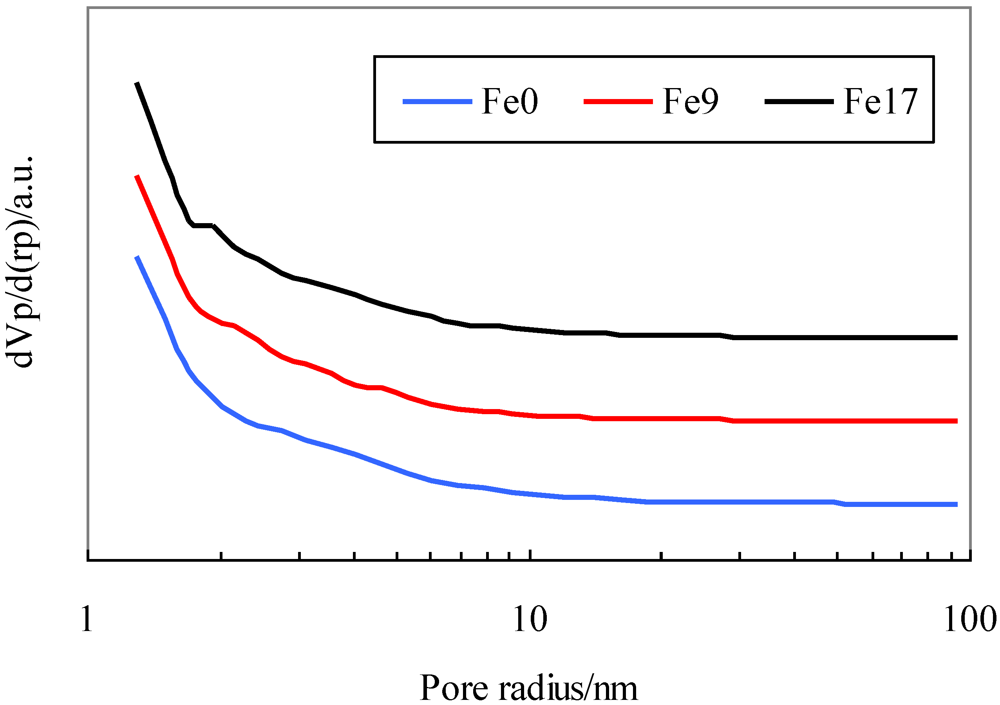
Figure 1 shows their pore distribution. Table 1 indicates that the addition of Fe to the activated carbon decreases the BET surface area by approximately 6% and that the textural parameters of Fe9 are similar to those of Fe17. Figure 1 indicates that all the activated carbons have not only micropores, but also mesopores with diameters up to 40 nm and that the addition of Fe has no effect on pore distribution.
Table 1. Physical properties of activated carbons. BET = Brunauer–Emmett–Teller.
SampleBET specific surface areaPore volumeAverage pore diameter
m2 g−1cm3(STP) g−1nm
Fe01206.3 277.2 2.0
Fe91126.0 258.7 2.0
Fe171128.5 259.3 2.0
Figure 1. Pore distribution for activated carbons.
Catalysts 02 00281 g001

2.2. Effect of Temperature on COS Capture

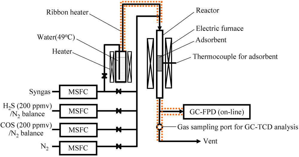
The effect of temperature on COS capture was investigated using Fe0 in order to understand removal mechanism for COS in the presence of product gas derived from biomass gasification. The product gas employed in the laboratory experiment was prepared throughout a bench-scale BTL plant operation with desulfurization and is denoted by syngas. The concentration of syngas was CO: 51.3 vol%, H2: 35.1 vol%, CH4: 5.2 vol%, CO2: 0.5 vol%, C2H4: 0.1 vol%, and N2: 7.7 vol%.
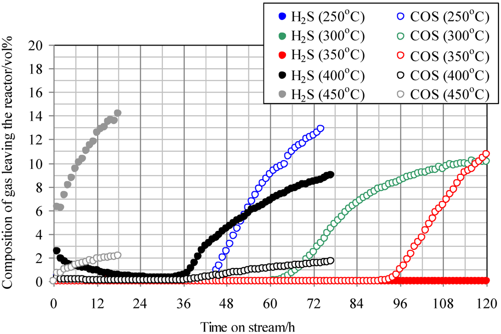
Figure 2 shows the temperature dependence of breakthrough curves using Fe0 when a mixture gas of syngas and COS was employed as the feed gas. The ratio of the volume flow rate of syngas and COS (200 ppmv in N2) was 9:1; therefore, feed gas with a COS concentration of 20 ppmv was supplied into the adsorbent layers. With increasing reaction temperature, the breakthrough time increased, exhibiting the longest time at 350 °C (97 h). However, with an increase in temperature to more than 400 °C, the breakthrough time, which was regarded as the time when the concentration of sulfur compounds in the gas leaving the reactor reached 1 ppmv, decreased and the gas leaving the reactor contained both COS and H2S. In the study by Sakanishi on COS removal using activated carbon, the gas leaving the reactor contained CO at 400 °C, while it contained no CO at 300 °C [15]. This result suggests that no COS decomposition reaction takes place at temperatures lower than 300 °C. However, COS is removed as a result of physical adsorption, and it decomposes well on the activated carbons at temperatures higher than 400 °C. In the present study, because H2S was detected at more than 400 °C, reaction (1) would have proceeded on the Fe0 surface.
Catalysts 02 00281 i001
Figure 2. Breakthrough curves for COS using Fe0 at different temperatures. (Feed gas; CO: 46.1 vol%, H2: 31.6 vol%, CH4: 4.7 vol%, CO2: 0.5 vol%, C2H4: 0.1 vol%, N2: 17.0 vol%, COS: 20 ppmv).Commercial activated carbon without modification is denoted by Fe0.
Catalysts 02 00281 g002
It is considered that inorganic matter is contained in Fe0. At 350 °C, COS would be adsorbed by physical adsorption and react well with inorganic matter while reaction (1) was not dominant. As a result, the breakthrough capacity at 350 °C exhibited the maximum value. However, at more than 400 °C, reaction (1) became dominant and H2S was produced.

2.3. Effect of Addition of Fe to Activated Carbons

The effect of addition of Fe to activated carbon on desulfurization behavior was investigated in the presence of H2S and COS. 
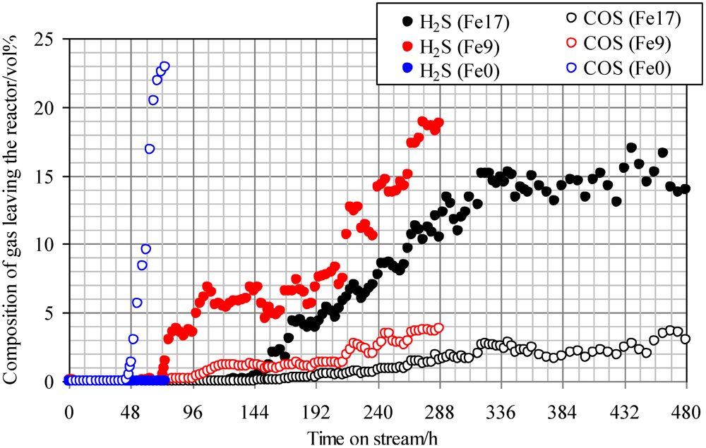
Figure 3 shows the breakthrough curves at 350 °C using Fe0, Fe9, and Fe17. The mixture gas of syngas, COS, and H2S was employed as a feed gas. The ratio of the volume flow rate of syngas, COS (200 ppmv in N2), and H2S (200 ppmv in N2) was 8:1:1; therefore, a feed gas with COS and H2S concentrations of 20 ppmv was supplied to the adsorbent layers. With increasing Fe content, the breakthrough time increased from 48 to 136 h. Apparently, the addition of Fe to activated carbons contributed to the simultaneous removal of H2S and COS. For Fe0, the COS concentration increased to 20 ppmv after the breakthrough, whereas no H2S was detected after the H2S breakthrough at 48 h. Comparing breakthrough behaviors using Fe0, shown in Figure 2 and Figure 3, the addition of H2S to the syngas containing COS led to a decrease in the breakthrough time from 97 h (Figure 2) to 51 h (Figure 3). This comparison indicates that the interaction of H2S and Fe0 is stronger than that of COS and Fe0, which is consistent with the result that H2S was produced at temperatures greater than 400 °C (Figure 2). Accordingly, H2S and COS could be removed simultaneously at 350 °C using Fe0 with a gas mixture containing H2S, COS, H2, CO, CO2, CH4, and N2, but it is relatively difficult for COS to be removed.
Figure 3. Breakthrough curves at 350°C. (Feed gas; CO: 41.0 vol%, H2: 28.1 vol%, CH4: 4.2 vol%, CO2: 0.4 vol%, C2H4: 0.1 vol%, N2: 26.3 vol%, H2S: 20 ppmv, COS: 20 ppmv), SV(350°C) = 1592 h−1. The two Fe-supported activated carbon samples with Fe contents of 9 wt% and 17 wt% are denoted by Fe9 and Fe17.
Catalysts 02 00281 g003
With increasing Fe content up to 17 wt%, the breakthrough time increased from 48 to 136 h. After the breakthroughs for Fe9 and Fe17, the concentrations of COS and H2S in the gas leaving the reactor were 5–6 ppmv and 30–33 ppmv, respectively. This result suggests that COS is converted to H2S on the Fe-supported activated carbons. Some portion of the COS supplied would react with inorganic matter contained in both Fe-supported activated carbon samples. The feed gas in the present study contains 28.1 vol% of H2. Therefore, reaction (1) is promoted on the surface of Fe9 and Fe17 to convert the residual portions of COS into H2S, followed by a sulfidation reaction of the Fe supported on the surface.

2.4. Effect of Steam on Simultaneous Removal of COS and H2S

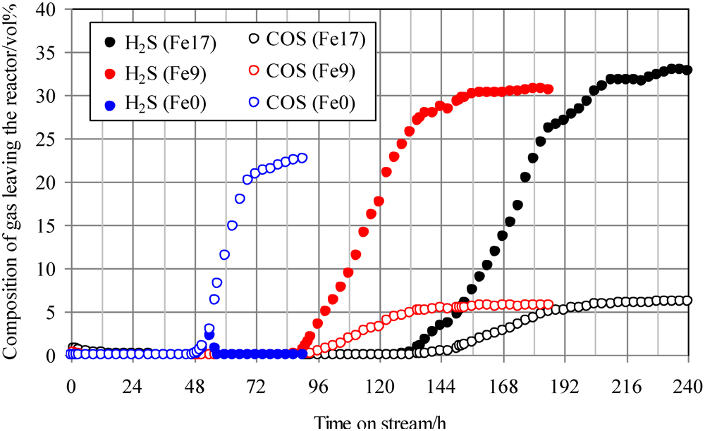
Figure 4 shows breakthrough curves at 350 °C using Fe0, Fe9, and Fe17. A mixture of syngas, COS, H2S, and steam was employed as feed gas. The ratio of the volume flow rate of syngas, COS, H2S, and steam was 8:1:1:1; therefore, a feed gas with COS and H2S concentrations of 18 ppmv on a wet basis was supplied to the adsorbent layers. Figure 4 indicates that with increasing Fe content, the breakthrough time increases. A comparison of the breakthrough behaviors with and without steam (Figure 3 and Figure 4) indicates that the presence of steam only slightly affected the breakthrough time. For Fe0, no H2S was produced after the breakthrough of COS, while for Fe9 and Fe17, the concentrations of H2S (15–20 ppmv) were higher than those of COS (3–4 ppmv) after the breakthrough. These results suggest that the presence of steam promotes reaction (2) on the Fe-supported activated carbons.
Catalysts 02 00281 i002
Figure 4. Breakthrough curves at 350°C using gas containing steam. (Feed gas; CO: 37.3 vol%, H2: 25.5 vol%, CH4: 3.8 vol%, CO2: 0.4 vol%, C2H4: 0.1 vol%, N2: 23.9 vol%, H2O: 9.1 vol%, H2S: 18 ppmv, COS: 18 ppmv), SV(350°C) = 1751 h1.
Catalysts 02 00281 g004
A comparison of H2S concentrations after the breakthrough, shown in Figure 3 and Figure 4, indicates that the concentration with steam (Figure 4) is lower than that without steam (Figure 3). Because the feed gas contained steam and H2, it is considered that Fe9 and Fe17 would promote reactions (1) and (2). Taking the H2S concentration after the breakthrough into account, the presence of steam would possibly lead to an increase in the number of adsorption sites for H2S. In a study by Adib et al. [20], steam had an affinity with the functional group on the surface of activated carbon and was therefore likely to be condensed. The removal of H2S was promoted by the presence of steam in the feed gas because of the interaction of condensed water and H2S [20]. In a study by Xie et al., the simultaneous removal of H2S and COS at temperatures greater than 420 °C was favored by using Fe‑supported CeO2 [21]. Lower temperatures are favorable for the promotion of reaction (2). In the present study, Fe-supported activated carbon would promote reactions (1) and (2) even at temperatures less than 420 °C.
The presence of steam in the feed gas decreased the breakthrough capacity of adsorbents for sulfur compounds [22]. In this study by Wakker et al., the breakthrough capacity for the simultaneous removal of H2S and COS using FeO/γ-Al2O3 decreased by 70% with increasing steam concentration up to 14 vol% [22]. The addition of steam to the feed gas led to the promotion of a reversible reaction (3).
Catalysts 02 00281 i003
In the present study, because Fe is supported on the activated carbon, it would be difficult to carry out a sulfidation reaction such as reaction (3) in the presence of steam. Reaction (2) is promoted; however, the amount of H2O consumed as a result of the reaction would be negligible compared to the steam concentration (9 vol%) in the feed gas. It is therefore considered that for Fe9 and Fe17, steam is mainly consumed by a reaction different from reaction (2).
For Fe17 after the breakthrough mentioned in Figure 4, the effect of temperature on gas composition was studied by changing the temperature of the Fe-supported activated carbon bed. Table 2 shows the temperature dependence of the composition on a dry basis of gas leaving the reactor. With increasing temperature up to 450 °C, the CO content decreased from 41.0 to 30.8 vol%, while the CO2 and H2 content increased from 0.4 to 7.5 vol% and from 28.1 to 30.5 vol%, respectively. This result indicates that the water-gas shift reaction (CO + H2O → CO2 + H2) proceeds with an increase in the temperature. In a study by Encinar et al., similar results were reported using Zn-supported carbonaceous materials [23]. Not only is steam consumed on the surface of Fe-supported activated carbons as a result of the water-gas shift reaction, but also reaction (2) and the sulfidation reaction of Fe are promoted at 350 °C. Accordingly the breakthrough times for Fe9 and Fe17 are much longer than that for Fe0, even in the presence of steam.
Table 2. Effect of temperature on composition of gas leaving the reactor.
TemperatureGas composition/vol% on a dry basisH2/CO
°CH2COCO2CH4C2H4N2-
20 a28.1 41.0 0.4 4.2 0.1 26.3 0.69
25027.1 39.8 0.6 4.0 0.1 28.3 0.68
30027.3 39.2 1.2 4.0 0.1 28.2 0.70
35027.4 38.7 1.7 4.0 0.1 28.1 0.71
40029.2 34.8 4.4 3.9 0.1 27.6 0.84
45030.5 30.8 7.5 3.9 0.1 27.2 0.99
a Feed gas.

2.5. Simultaneous Removal of Impurities from Product Gas Derived from Woody Biomass Gasification Using Fe-Supported Activated Carbon

Figure 5 shows a schematic diagram of the bench-scale BTL plant used to capture impurities and the location of the sampling ports for collecting gas, tar, and particles. In the gasification step, the oxygen-enriched air/CO2 was performed. The product gas flow rate was 40 Nm3 h−1. Fe9 as an adsorbent was packed into activated filters A and B. Table 3 shows the analytical results for feedstock (eucalyptus chips, 20–30 mm) in a bench-scale gasification operation producing the syngas cylinders mentioned above.
Figure 5. Schematic diagram for gas cleaning of product gas derived from biomass gasification.
Catalysts 02 00281 g005
Table 3. Results of feedstock analysis.
Ultimate analysis/wt% daf basisProximate analysis/wt%
CHNS aO bMoistureVolatile matterFixed carbonAsh
50.75.90.20.01543.2 13.1 70.9 15.4 0.6
a Ion chromatography; bBy difference.

2.5.1. Sulfur-Compound Removal and Water-Gas Shift Reaction

Figure 6 shows the changes in temperatures of the gasifier (combustion zone, reduction zone, and gasifier exit) and activated filters A and B as a function of time. During the oxygen-enriched air/CO2 gasification operation (10:23–17:41), the temperature in the combustion zone (900–1200 °C) was sufficiently high, while temperatures in the reduction zone and gasifier exit remained steady at approximately 820 and 480 °C, respectively. When the product gas passed through both activated filters (13:30–17:00), the temperatures of filters A and B were 250–350 and 10–200 °C, respectively. Although not shown, the temperatures of the activated filter A and B were 320–350 and 60–170 °C steady in which tar, particles, and gas were collected from each sampling port.
Figure 6. Change in temperatures of gasifier and activated carbon filters as a function of time.
Catalysts 02 00281 g006
Table 4 shows the composition of gas collected from SP1, SP2, and SP4. That of gas from SP1 was H2: 30.4 vol%, CO: 44.8 vol%, CO2: 18.6 vol%, CH4: 3.6 vol%, and N2: 1.8 vol%; these values are similar to those in our previous paper [24]. The compositions of H2S and COS were 15.7 and 7.2 ppmv, respectively, while that of gas collected from SP2 was 0.1 and 0.0 ppmv, which was less than the detectable limit (5 ppbv). The composition of gas from SP4 (after the roots blower) is also shown in Table 4. The wood feedstock contained 13.1 wt% of moisture, as indicated in Table 3. The gas supplied to activated carbon filter A would contain approximately 10 vol% of steam, assuming that the reaction relating to steam such as steam gasification (C + H2O → CO + H2) did not proceed in the gasifier because the product gas flow rate was 40 Nm3 h−1. The steam content of the gas supplied to filter A was almost the same as that employed in the laboratory experiment (9.1 vol%). The ratio of H2/CO in the gases collected from SP1 and SP2 increased from 0.7 to 1.2. This result indicates that the water-gas shift reaction proceeds though activated carbon filter A. In Table 2, the ratio of H2/CO in the feed gas at 250 °C was 0.68, while that at 350 °C was 0.71 in the laboratory test. The W/F in the bench test was 1.875 kg h Nm−3 and was about 3.8 times higher than that in the laboratory test (0.5 kg h Nm−3). Therefore, the advance in the water-gas shift reaction on a bench test would be caused by higher W/F, although the Fe content was almost half that used in the laboratory test. The CO2 content in the gas collected from SP4 was lower than that from SP2. This result is attributed to the dissolution of CO2 by passing the gas through the scrubber. The product gas passed through the activated carbon filters for a total of 10 h; however, the gas leaving activated carbon filter A contained no sulfur compounds.
Table 4. Gas composition at SP1, SP2, and SP4.
SPH2COCO2CH4C2H4C2H6N2H2SCOSH2/CO
vol%ppmv-
SP130.4 44.8 18.6 3.6 0.7 0.1 1.8 15.7 7.2 0.7
SP235.6 28.6 27.9 3.9 0.8 0.2 3.0 0.1 0.0 1.2
SP434.5 31.6 25.9 3.8 0.9 0.2 3.1 0.0 0.0 1.1

2.5.2. Removal of Tar and Particles

Table 5 shows the concentrations of tar and particles in the gases collected from SP1, SP2, and SP3. The concentrations of tar and particles from SP1 were 2428 and 2244 mg Nm−3, respectively. These results are similar to the concentrations of tar (0.1–5 g/Nm3) [25] and particles (0.1–8 g Nm−3) [26] in the product gas obtained in the gasification with air at atmospheric pressure using a down-draft fixed-bed gasifier. These results suggest that the addition of pure oxygen and CO2 to air as a gasifying agent only slightly affects the emission behavior of tar and particles. By passing through activated carbon filters A and B, the concentrations of tar and particles decreased to 305 and 662 mg Nm−3, respectively, then to 102 and 181 mg Nm−3, respectively. Accordingly, the concentrations of tar and particles decreased by 1/24 and 1/12, respectively, compared to those in the feed gas (SP1).
Table 5. Concentrations of tar and particles in the gases collected from SP1, SP2, and SP3 (samplingports).
SPTarParticles
mg Nm−3mg Nm−3
SP124282244
SP2305662
SP3102181
Figure 7 shows the GC-MS spectra of a 2-propanol solution of tar collected from SP1, SP2, and SP3. Table 6 shows tar identified by the GC-MS spectra. The gas collected from SP1 contained one- and four-ring polycyclic aromatic hydrocarbons (PAHs), benzene (a), toluene (b), 1,3,5,7-cyclooctatetraene (e), indene (j), naphthalene (k), 2-methylnaphthalene (l), 1-methylnaphthalene (m), and biphenylene (p). Figure 7 shows that the peaks assigned to anthracene (s), fluoranthene (t), and pyrene (u) in SP1 were not detected in SP2. This result indicates that three- and four-ring PAHs were removed at 320–350 °C using Fe-supported activated carbon. A comparison of SP2 and SP3 indicates that all the peaks except that of benzene (a) were detected in the spectrum for SP3. This result indicates that one- and two-ring PAHs, except that of benzene, were removed at 60–170 °C. Mastral et al. reported the removal of naphthalene, phenanthrene, and pyrene at 150 °C using activated carbons with micropores [27,28]. Taking into account the fact that the average molecular diameters of naphthalene, phenanthrene, and pyrene are 0.62, 0.70, and 0.75 nm [29], respectively, and that the representative diameter of the micropores is 2 nm, tar with its higher boiling point is removed due to capillary condensation [28]. The phenanthrene adsorption capacity decreases with increasing steam content [30]. In the present study, the gas supplied to the activated carbon filter contained approximately 10 vol% of steam and the mean free path of tarry compound molecules increased in length due to higher temperatures (320–350 °C), which would make the diffusion into the pores and adsorption for tar difficult. The activated carbons employed in the present study had mesopores with diameters up to 40 nm, as shown in Figure 1. It is considered that three- and four-ring PAHs are removed from the gas stream because of capillary condensation after they diffuse into the mesopores. Some compounds in the gas from SP2 were detected, while these same compounds were not detected in the gas from SP1. This result could be attributed to the promotion of an isomerization reaction on the Fe-supported activated carbons. We will investigate this in the near future. Lowering the temperature of activated carbon filter B would lead to a decrease in the mean free path of one- and two-ring PAHs, except benzene, and thus make diffusion into the pores easy.
Figure 7. GC-MS spectra of tar in the gas collected at SP1, SP2, and SP3.
Catalysts 02 00281 g007
Table 6. Qualitative analysis result of collected tar.
SymbolCompound name
aBenzene
bToluene
cEthylbenzene
do-Xylene
e1,3,5,7-Cyclooctatetraene
f1-Ethyl-3-methyl benzene
gPhenol
hBenzofuran
iIndane
jIndene
kNaphthalene
l2-Methyl naphthalene
m1-Methyl naphthalene
nBiphenyl
o1-Ethyl naphthalene
pBiphenylene
qAcenaphthene
rFluorene
sAnthracene
tFluoranthene
uPyrene

2.6. Improvement of Gas-Cleaning Process Using Fe-Supported Activated Carbons for BTL System

When the cleaned gas is compressed using a compressor before the FT synthesis reaction in the BTL total system, the typical tolerance levels for tar and particles are 50–500 mg Nm−3 and 0.02 mg Nm−3, respectively [31]. If the tarry compound consists only of benzene, the tolerance level is 2500 ppmv at 4 MPa, 20 °C [26]. In a study by Garcia et al., the phenanthrene adsorption capacity decreased with increasing CO and CO2-type groups on the surface of activated carbons using H2O2 and HNO3 [
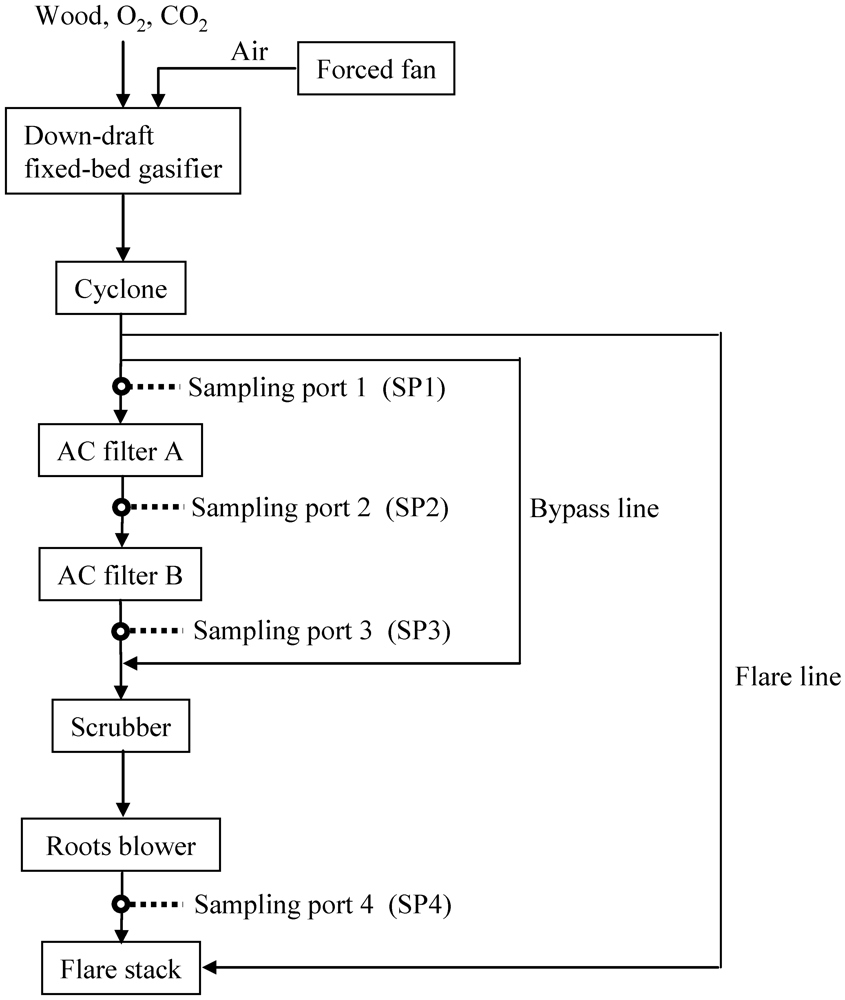
32]. This suggests that aromatic compounds are removed as a result of the interaction between the π-electron-rich regions of the graphene layers and the aromatic rings of phenanthrene. It is possible that benzene molecules are removed simultaneously by modifying the surface of Fe-supported activated carbons. As a result, tar, except that composed of benzene, was removed and its concentration decreased below the tolerance level, while the removal of particles was not accomplished. Since particles are solid at temperatures less than in the gasifier, they should be physically removed. At present, we have no regeneration system for blockage of activated carbon filters due to particles and need to exchange new filters after a prolonged time on stream. In order to protect the activated deactivation due to particles, we suggest the process in which particles are removed at more than 350 °C between the cyclone and activated filters. For example the cleaned gas without small particles could be supplied to the activated carbon filter through a process such as electrostatic precipitator.
In the present study, both the simultaneous removal of impurities and the promotion of a water-gas shift reaction were demonstrated using Fe-supported activated carbon packed into two filters on a bench scale. Sulfur compounds, three- and four-ring PAHs, and particles were removed and a water-gas shift reaction was promoted through the first filter. Except that of benzene, one- and two-ring PAHs were subsequently removed through the second filter. Apparently the addition of Fe to activated carbon produced the active sites for desulfurization and water gas shift reaction. Probably the heavy tar would be adsorbed on not only catalytically active Fe, but also on the surface of activated carbon. Therefore the textual parameter of activated carbons would affect the lifetime for the removal of impurities. We believe that not only the lifetime, but also the absorption capacity of heavy tar would increase with an increase in the surface area and pore size. The lifetime of Fe-supported activated carbon employed in the first filter and the choice of adsorbent used in the second filter are important considerations for optimizing the gas-cleaning process. In our proposed process, it is necessary to renew the Fe-supported activated carbon after an extended time on stream, which makes the economics less favorable. In the present paper, unfortunately we did not study the lifetime of the activated carbon filter. Therefore in the future it will be investigated together with the effect of adsorption capacity for sulfur compounds and the tar, and pressure drop through the bench plant operation.
A product gas with a H2/CO ratio of 1.2 was obtained by the promotion of the water-gas shift reaction. Because a feed gas with a H2/CO ratio of one is desirable for dimethyl ether synthesis from syngas [33], the water-gas shift process can be omitted if the proposed gas-cleaning process is optimized. However, because a feed gas with H2/CO of 2.0–2.2 is favorable for hydrocarbon and alcohol synthesis from syngas [34,35,36], it is necessary to develop a more effective reaction.
It is also important to study inexpensive adsorbents and their regeneration. In order to make heavy tarry compound molecules diffuse easily into the pores, even at higher temperatures, for the water-gas shift reaction, Fe-supported inexpensive carbonaceous materials with mesopores up to 40 nm could be used. For example, unreacted char obtained in the gasification process can be employed as an adsorbent in the first filter. A saturated adsorbent with sulfur compounds and heavy tar could be used as a heating fuel. In this study, the one- and two-ring PAHs, except that of benzene and sulfur compounds, were adsorbed on the surface of activated carbons used in the second filter at temperatures less than 200 °C. It is possible that such compounds can be collected under an inert gas stream at temperatures greater than 200 °C; these collected compounds could then be useful as raw materials for chemicals and the adsorbent reused. In the near future, we will report on the lifetime and regeneration of adsorbents based on the results of a laboratory test.

3. Experimental Section

3.1. Desulfurization of Gas Using Activated Carbons on a Laboratory Scale

Fe was supported on commercial activated carbon using the following impregnation method. The activated carbon was immersed in an aqueous solution ([Fe(NO3)3]aq = 3.6 mol L−1) of iron(III) nitrate enneahydrate (Wako Pure Chemical Industries, Ltd.) and dried at 80 °C for 12 h in an oven. The samples were then calcined in a muffle furnace in N2 at 600 °C for 2 h to remove moisture. Figure 8 shows a schematic diagram of the experimental apparatus for H2S and COS capture on a laboratory scale. The inner and outer diameters of the quartz-glass reactor tube were 10 and 12 mm, respectively. The packing density of the activated carbon was Fe0: 0.35 g cm−3, Fe9: 0.41 g cm−3, Fe17: 0.47 g cm−3. The adsorbents were kept in an isothermal area (15 cm length) inside an electric heater. The temperature of the adsorbents was regarded as the temperature of the reactor wall and was adjusted by a temperature controller. Syngas cylinders (CO: 51.3 vol%, H2: 35.1 vol%, CH4: 5.2 vol%, CO2: 0.5 vol%, C2H4: 0.1 vol%, and N2: 7.7 vol%) were produced by operating a BTL plant. Two cylinders of H2S (200 ppmv) and COS (200 ppmv), with the balance being N2, were employed. Each gas was supplied to the activated carbon inside the reactor through calibrated mass flow controllers. The ratio of the weight of the activated carbon to the total feed gas on a dry basis (W/F) was 0.5 kg h Nm−3. The desulfurization temperature was in the range 250–450 °C. The gas leaving the reactor was analyzed using gas chromatographs with FPD (6890N, Agilent Technologies) and with TCD (GC-8A; Shimadzu). FT synthesis catalysts are easily deactivated by the sulfur compounds in the syngas [37]; therefore, the breakthrough time was regarded as the time when the concentration of sulfur compounds in the gas leaving the reactor reached 1 ppmv.
Figure 8. Scheme of the fixed-bed reactor for H2S and COS capture.
Catalysts 02 00281 g008

3.2. Removal of Impurities Using Fe-Supported Activated Carbons on a Bench Scale

Figure 5 shows a schematic diagram of the bench-scale BTL plant used to capture impurities and the location of the sampling ports for collecting gas, tar, and particles. The apparatus contained a down-draft fixed-bed gasifier (capacity: 1.44 t day−1 on a wet basis) [38], a cyclone, activated filters A and B, a scrubber, and a roots blower. Particulates containing inorganic matter, unreacted char, and relatively large particles were removed by the cyclone. Relatively small particles remaining in the gas stream were removed downstream of the cyclone. Two activated carbon filters (id: 710 mm, od: 880 mm, height: 890 mm) were installed in series and heated by electric heaters. The product gas flow rate was adjusted to 40 Nm3 h−1 using the roots blower.
In the gasification step, the feedstock was gasified into the syngas using oxygen-enriched air and CO2 as a gasifying agent (Figure 5). The inner temperature was increased by supplying air to the gasifier by a forced fan. Because the gas leaving the cyclone contained a significant amount of tar as temperatures increased, the gas was combusted using a flare stack through a flare line. When the target temperature was reached, the gas leaving the cyclone was fed into the scrubber through a bypass line using the roots blower after the forced fan stopped. Oxygen (7 Nm3 h−1) and CO2 (2 Nm3 h−1) were supplied into the gasifier using calibrated mass flow controllers. Approximately 1 Nm3 h−1 of air was also introduced into the gasifier because the amount of gasifying agent was limited when the product gas flow rate was adjusted to 40 Nm3 h−1. As a result, delivery of the gas mixture N2/O2/CO2 (=7/73/20 vol%) into the gasifier was realized as oxygen‑enriched air and CO2. Once the temperature for the gasifier reached equilibrium and the inner temperature for activated carbon filter A reached the desired temperature, the gas leaving the cyclone was delivered into the activated filters A and B. Activated carbon filter B was heated by the gas leaving activated carbon filter A.
In the dry gas cleaning step, approximately 75 kg of Fe9 as an adsorbent was packed into each activated filter. The temperature of the activated carbon samples was monitored using thermocouples installed at the axial and radial center of the layer. The ratio of the weight of the adsorbent to product gas flow rate per one tower (W/F) was 1.875 kg h Nm−3. The authors previously reported that by using commercial activated carbon on a laboratory scale, heavy tar was removed at 400 °C from the product gas derived from biomass gasification, and aromatic compounds with one and two rings as model compounds of light tar were effectively removed at 150 °C [16,17]. The desired temperature of activated filter A was 320–350 °C, taking the effective removal of sulfur compounds mentioned in the present study and heavy tar [16] into account. The temperature of activated filter B was 60–170 °C for removal of light tar [17]. Tar and particles were collected for 90 min from SP1, SP2, and SP3 according to guidelines for sampling and analysis of tar and particles [39].
The gas collected at each sampling port was analyzed by gas chromatographs with TCD (Micro GC 3000A, Agilent Technologies) and FPD, as mentioned above. The tars were qualitatively analyzed by gas chromatography-mass spectrometry (GC-MS; GC-2010; Shimadzu).

4. Conclusions

In a laboratory test under a feed gas flow without steam and with Fe contents ranging from 0 to 17%, the breakthrough time increased from 48 to 136 h. The reaction COS + H2 → H2S + CO was promoted on the surface of Fe-supported activated carbon. In the simultaneous removal of H2S and COS using Fe-supported activated carbon under a feed gas flow with steam, the reaction COS + H2O → H2S + CO2 and a water-gas shift reaction were promoted. The breakthrough time with steam was almost the same as that without steam; however, the adsorption capacity of sulfur compounds with steam was higher than that without steam.
On a bench-scale test, the sulfur compounds, three- and four-ring PAHs, and particles were removed and a water-gas shift reaction was promoted through the first filter packed with Fe9 at 320–350 °C. The concentrations of H2S and COS decreased to less than 0.1 ppmv and a gas with a H2/CO ratio of 1.2 was obtained. Particles and one- and two-ring PAHs, except in the case of benzene, were subsequently removed through the second filter at 60–170 °C. On passing through the two activated carbon filters, the concentrations of tar and particles decreased from 2428 to 102 mg Nm−3 and from 2244 to 181 mg Nm−3, respectively.

Acknowledgments

The authors are deeply thankful to Hideyuki Yokoyama, Nobuhisa Tanabe, Shou Hiasa, and Yoshie Nakashima for their experimental work.

References

  1. Minowa, T.; Hanaoka, T.; Yokoyama, S. Process evaluation of biomass to liquid fuel production system with gasification and liquid fuel synthesis. Stud. Surf. Sci. Catal. 2004, 153, 79–84. [Google Scholar]
  2. Sunde, K.; Brekke, A.; Solberg, B. Environment impacts and costs of woody Biomass-To-Liquid (BTL) production and use—A review. Forest Policy Econ. 2011, 13, 591–602. [Google Scholar]
  3. Devi, L.; Ptasinski, K.J.; Janssen, F.J.J.G. A review of the primary measures for tar elimination in biomass gasification processes. Biomass Bioenergy 2003, 24, 125–140. [Google Scholar]
  4. Brandt, P.; Larsen, E.; Henriksen, U. High tar reduction in a two-stage gasifier. Energy Fuels 2000, 14, 816–819. [Google Scholar]
  5. Gil, J.; Corella, J.; Aznar, M.P.; Caballero, M.A. Biomass gasification in atmospheric and bubbling fluidized bed. Effect of the type of gasifying agent on the product distribution. Biomass Bioenergy 1999, 17, 389–403. [Google Scholar] [CrossRef]
  6. Jansen, J.C.; Jonsson, K.; Hagman, M. Biological detoxification of tar-water. Water Sci. Technol. 2002, 46, 59–65. [Google Scholar]
  7. Nakamura, K. Status of EAGLE project: Multi-purpose coal gasification technology development (in Japanese). J. Jpn. Inst. Energy 2007, 86, 321–325. [Google Scholar]
  8. Gonzalez, J.M.; Roman, S.; Engo, G.; Encinar, J.M.; Martinez, G. Reduction of tars by dolomite cracking during two-stage gasification of olive cake. Biomass Bioenergy 2011, 35, 4324–4330. [Google Scholar]
  9. Andres, J.M.; Narros, A.; Rodriguez, M.E. Behaviour of dolomite, olivine and alumina as primary catalysts in air-steam gasification of sewage sludge. Fuel 2011, 90, 521–527. [Google Scholar]
  10. Corella, J.; Orio, A.; Toledo, J.M. Biomass gasification with air in a fluidized-bed: Exhaustive tar elimination with commercial steam reforming catalyst. Energy Fuels 1999, 13, 702–709. [Google Scholar]
  11. Nordgreen, T.; Liliedahl, T.; Sjostrom, K. Metallic iron as a tar breakdown catalyst related to atmospheric, fluidized bed gasification of biomass. Fuel 2006, 85, 689–694. [Google Scholar]
  12. Haibo, L.; Tianhu, C.; Xianlong, Z.; Jinhu, L.; Dongyin, C.; Lei, S. Effect of additives on catalytic cracking of biomass gasification tar over a nickel-based catalyst. Chin. J. Catal. 2010, 31, 409–414. [Google Scholar]
  13. Dou, B.; Gao, J.; Sha, X.; Baek, S.W. Catalytic cracking of tar component from high-temperature fuel gas. Appl. Therm. Eng. 2003, 23, 2229–2239. [Google Scholar]
  14. Lu, C.Y.; Wey, M.Y.; Fu, Y.H. The size, shape, and dispersion of active sites on AC-supported copper nanocatalysts with polyol process: The effect of precursors. Appl. Catal. A Gen. 2008, 344, 36–44. [Google Scholar] [CrossRef]
  15. Sakanishi, K.; Wu, Z.; Matsumura, A.; Saito, I.; Hanaoka, T.; Minowa, T.; Tada, M.; Iwasaki, T. Simultaneous removal of H2S and COS using activated carbons and their supported catalysts. Catal. Today 2005, 104, 94–100. [Google Scholar]
  16. Hanaoka, T.; Sakanishi, K.; Minowa, T. Hot gas cleaning of producer gas from biomass gasification using carbonaceous materials as a bed additive. J. Jpn. Inst. Energy 2004, 83, 828–831. [Google Scholar]
  17. Hu, X.; Hanaoka, T.; Sakanishi, K.; Shinagawa, T.; Matsui, S.; Tada, M.; Iwasaki, T. Removal of tar compounds produced from biomass gasification using activated carbons. J. Jpn. Inst. Energy 2007, 86, 707–711. [Google Scholar]
  18. Phuphuakrat, T.; Namioka, T.; Yoshikawa, K. Tar removal from biomass pyrolysis gas in two-step function of decomposition and adsorption. Appl. Energy 2010, 87, 2203–2211. [Google Scholar]
  19. Itaya, Y.; Kawahara, K.; Lee, C.W.; Kobayashi, J.; Kobayashi, N.; Hatano, S.; Mori, S. Dry gas cleaning process by adsorption of H2S into activated cokes in gasification of carbon resources. Fuel 2009, 88, 1665–1672. [Google Scholar]
  20. Adib, F.; Bagreev, A.; Bandosz, T.J. Analysis of the relationship between H2S removal capacity and surface properties of unimpregnated activated carbons. Environ. Sci. Technol. 2000, 34, 686–692. [Google Scholar]
  21. Xie, W.; Chang, L.; Wang, D.; Xie, K.; Wall, T.; Yu, J. Removal of sulfur at high temperatures using iron-based sorbents supported on fine coal ash. Fuel 2010, 89, 868–873. [Google Scholar]
  22. Wakker, J.P.; Gerritsen, A.W.; Moulijn, J.A. High temperature H2S and COS removal with MnO and FeO on γ-Al2O3 acceptors. Ind. Eng. Chem. Res. 1993, 32, 139–149. [Google Scholar]
  23. Encinar, J.M.; Gonzalez, J.F.; Rodriguez, J.J.; Ramiro, M.J. Catalysed and uncatalysed steam gasification of eucalyptus char: Influence of variables and kinetics study. Fuel 2001, 80, 2025–2036. [Google Scholar]
  24. Hanaoka, T.; Miyazawa, T.; Nurunnabi, M.; Hirata, S.; Sakanishi, K. Liquid fuel production from woody biomass via oxygen-enriched air/CO2 gasification on a bench scale. J. Jpn. Inst. Energy 2011, 90, 1072–1080. [Google Scholar]
  25. Stevens, D.J. Hot Gas Conditioning: Recent Progress with Larger-Scale Biomass Gasification Systems; NREL-SR-510-29952; National Renewable Research Laboratory: Golden, CO, USA, 2001. [Google Scholar]
  26. Baker, E.G.; Brown, M.D.; Moore, R.H.; Mudge, L.K.; Elliott, D.C. Engineering Analysis of Biomass Gasifier Product Gas Cleaning Technology; PNL-534; Biomass Energy Technology Division, Pacific Northwest Laboratory: Richland, WA, USA, 1986. [Google Scholar]
  27. Mastral, A.M.; Garcia, T.; Callen, M.S.; Navarro, M.V.; Galban, J. Removal of naphthalene, phenanthrene, and pyrene by sorbents from hot gas. Environ. Sci. Technol. 2001, 35, 2395–2400. [Google Scholar]
  28. Mastral, A.M.; Garcia, T.; Murillo, R.; Callen, M.S.; Lopez, J.M.; Navarro, M.V. Measurements of polycyclic aromatic hydrocarbon adsorption on activated carbons at very low concentrations. Ind. Eng. Chem. Res. 2003, 42, 155–161. [Google Scholar]
  29. Bondi, A. van der Waals volumes and radii. J. Phys. Chem. 1964, 68, 441–451. [Google Scholar]
  30. Mastral, A.M.; Garcia, T.; Murillo, R.; Callen, M.S.; Lopez, J.M.; Navarro, M.V. Moisture effects on the phenanthrene adsorption capacity by carbonaceous materials. Energy Fuels 2002, 16, 205–210. [Google Scholar]
  31. Milne, T.A.; Evans, R.J.; Abatzoglou, N. Biomass Gasifier “Tars”: Their Nature, Formation, and Conversion; NREL/TP-570-25357; National Renewable Energy Laboratory: Golden, CO, USA, 1998. [Google Scholar]
  32. Garcia, T.; Murillo, R.; Amoros, D.C.; Mastral, A.M.; Solano, A.L. Role of the activated carbon surface chemistry in the adsorption of phenanthrene. Carbon 2004, 42, 1683–1689. [Google Scholar]
  33. Li, Y.; Wang, T.; Yin, X.; Wu, C.; Ma, L.; Li, H.; Lv, Y.; Sun, L. 100 t/a-scale demonstration of direct dimethyl ether synthesis from corncob-derived syngas. Renew. Energy 2010, 35, 583–587. [Google Scholar]
  34. Tijmensen, M.J.A.; Faaij, A.P.C.; Hamelinck, C.N.; van Hardeveld, M.R.M. Exploration of the possibilities for production of Fischer Tropsch liquids and power via biomass gasification. Biomass Bioenergy 2002, 23, 129–152. [Google Scholar]
  35. Dry, M.E. High quality diesel via the Fischer-Tropsch process—A review. J. Chem. Technol. Biotechnol. 2001, 77, 43–50. [Google Scholar]
  36. Subramani, V.; Gangwal, S.K. A review of recent literature to search for an efficient catalytic process for the conversion of syngas to ethanol. Energy Fuels 2008, 22, 814–839. [Google Scholar]
  37. Boerrigter, H.; Calis, H.P.; Slort, D.J.; Bodenstaff, H. Gas Cleaning for Integrated Biomass Gasification (BG) and Fischer-Tropsch (FT) Systems; Experimental Demonstration of Two BG-FT Systems. In Proceedings of the 2nd World Conference and Technology Exhibition on Biomass for Energy, Industry and Climate Protection, Rome, Italy, 2004; pp. 51–56.
  38. Hanaoka, T.; Liu, Y.; Matsunaga, K.; Miyazawa, T.; Hirata, S.; Sakanishi, K. Bench-scale production of liquid fuel from woody biomass via gasification. Fuel Proc. Technol. 2010, 91, 859–865. [Google Scholar]
  39. Neeft, J.P.A.; Knoef, H.A.M.; Zielke, U.; Sjostrom, K.; Hasler, P.; Simell, P.A.; Dorrington, M.A.; Thomas, L.; Abatzoglou, N.; Deutch, S.; Greil, C.; Buffinga, G.J.; Brage, C.; Suomalainen, M. Guideline for Sampling and Analysis of Tar and Particles in Biomass Producer Gases; Energy project ERK6-CT1999-20002 (Tar protocol), Version 3.3; European Commission (DGXII),Netherlands Agency for Energy and the Environment (NOVEM),Swiss Federal Office of Education and Science, Danish Energy Agency (Energistyrelsen),US Department of Energy (DoE),National Resources Canada: Brussels, Belgium, 2002. [Google Scholar]

