

Research on the Influencing Factors of AUV Hovering Control in Null-Speed State
by
Jianguo Wang
1,
Chunmeng Jiang
2,*,
Lei Wan
3,
Yimei Zhou
1,
Gangyi Hu
1,
Xide Cheng
4 and
Gongxing Wu
5 1
China Ship Development and Design Center, Wuhan 430064, China
2
Wuhan Institute of Shipbuilding Technology, Wuhan 430050, China
3
School of Naval Engineering, Harbin Engineering University, Harbin 150001, China
4
School of Naval Architecture, Ocean and Energy Power Engineering, Wuhan University of Technology, Wuhan 430063, China
5
College of Ocean Science and Engineering, Shanghai Maritime University, Shanghai 201306, China
*
Author to whom correspondence should be addressed.
J. Mar. Sci. Eng. 2024, 12(5), 725; https://doi.org/10.3390/jmse12050725
Submission received: 27 March 2024
/
Revised: 16 April 2024
/
Accepted: 24 April 2024
/
Published: 27 April 2024
(This article belongs to the Special Issue Unmanned Marine Vehicles: Navigation, Control and Sensing)
Abstract
:Intelligent underwater vehicles hover by way of a hovering control system. To provide design inputs and maneuver guidance, this study focused on the characteristics of intelligent underwater vehicles during hovering control with the propulsion system shut down, established a mathematical model of hovering control and determined injection and drainage functions based on optimal control theory. From analysis simulation experiments, the influence laws of control parameters, control timing and rate of injection and drainage control upon hovering control were deduced. It is proposed that, at the time of control parameter selection, the continuous injection and drainage rate at each time should be reduced as far as possible to relieve the demand on the volume of the reservoir when the requirement of depth control accuracy has been satisfied. In addition, the injection and drainage control should initiate when depth changes exceed 0.5 m. Suggestions are included on the minimum injection and drainage rate required for different initial disturbances. The proposed suggestions guide the design of hovering control systems and hovering control over intelligent underwater vehicles.
1. Introduction
The ocean is a treasury of resources vital to human survival and the second most significant strategic space after land. The progress of intelligent control [1], numerical simulation [2], information fusion [3], data mining [4], parameter optimization [5], virtual reality [6], artificial intelligence [7], high-end chips [8] and large-scale integrated circuits [9] has also brought about remarkable breakthroughs in the technologies of intelligent underwater vehicles. Intelligent underwater vehicles are applicable to operations in harsh environments which divers and equipment have difficulty accessing, such as during deep-sea resource exploration [10], submarine oil and gas pipeline inspection [11], dam exploration [12], aircraft or shipwreck salvage [13], submarine cable maintenance [14] and submarine cable laying [15], etc. The prospects of intelligent underwater vehicles have been seen in both military and civilian fields [16,17,18,19], and they have become an important tool in different complex underwater tasks. The control performance has always been a priority in the controller design of the strongly nonlinear and coupled system of underwater vehicles [20,21]. This is not only for the successful completion of the tasks but also for the maximum utilization of the limited power supply.
In-depth research and studies have been carried out on hovering and the depth control of underwater vehicles, with different methods proposed. A PD-based sliding mode controller for hovering tilting-thruster underwater vehicles was designed [22]. PD control can achieve stable hovering in a certain range, and the combination of PD and sliding mode control can achieve hovering at a lower speed. Simulation experiments were conducted based on the triggering conditions of the propulsion system, the results of which verified the hovering control performance of the proposed design. The hovering control of a biomimetic four-fin underwater vehicle was studied [23]. The new mechanical design and special application of the bionic underwater vehicle ruled out the traditional AUV control methods. Therefore, a new single-module control architecture was put forward for different application scenarios. The simulation experiments verified the effectiveness of the proposed method in hovering control. In-water visual ship hull inspection via a hovering underwater vehicle with stereo vision was studied [24]. The method proposed included path planning, navigation, hovering control and detection. The simulation experiments proved the effectiveness of the method in hovering control. The hovering control of an underwater vehicle with tilting thrusters was studied, and its hovering performance was improved [25]. The maneuverability of the underwater vehicle was evaluated based on analysis of the forces and moments. A PID-based control strategy involving decoupling and compensation was designed to overcome the nonlinearity caused by the tilting system. The feasibility of the strategy was proved in the simulation experiments. A depth controller for a biomimetic underwater vehicle was proposed [26]. The PID controller and sliding mode controller were contrasted. The relationship between the desired depth, horizontal rudder angle and control signal parameters was deduced. Simulation experiments showed that the sliding mode controller gave superior results to the PID controller. The modeling and motion control of AUVs were studied [27]. A six-degrees-of-freedom model for rotary and heaving control was established. A hybrid controller based on sliding mode and PID control was designed to improve the closed-loop response. Simulation experiments proved that the hybrid controller had better depth control performance than the PID controller. With a simple structure and few parameters, the classic S-plane method resulted in the combination of PD control structure and fuzzy logic. It well met the control accuracy requirements in underwater depth control. The performance of the S-plane method was verified in pool tests and sea trials. The S-plane method has become one of the most commonly used methods for underwater vehicle control [28,29,30]. Since the situational static load is not considered in the classical S-plane method, the control effects would be influenced, theoretically. To counteract such an influence, a novel S-plane method considering the situational static load was studied [31]. A method for six-degrees-of-freedom motion control considering the inclination angles was also proposed [32]. The above control methods primarily rely on the propulsion system to achieve hovering control or depth control at a certain speed, and are generally based on combinations of thrusters or propellers and control surfaces [33,34,35]. Studies and discussions on hovering control by way of water injection or drainage with the propulsion system shut down are relatively scarce.
Hovering control of an intelligent underwater vehicle means the maintenance or change of depth after forward movement ceases and the thrusters are shut down, which is of great military significance and tactical importance. When the thrusters are shut down, the lubricating oil pump and cooling pump also stop working. Since the blades stop rotating, the vibration noise between the propeller blades and the shafting and the cavitation noise as the result of periodic changes of the thrusting forces disappear. There is no relative movement between the vehicle body and the seawater, hence the minimum hydrodynamic noise [36,37,38,39]. The lowered noise makes the underwater vehicle quiet and covert, greatly improving sonar detection range and search capability. Moreover, the hovering control avails electric energy saving, extends the service time and reduces the exposure of the underwater vehicles. It is the great military significance and tactical value that boost the increasing number of studies on hovering control technology, with extensive research on the success, noise reduction and energy conservation of hovering control. Some of the existing research findings only realize depth control or hovering control with the propulsion system operating. However, few studies have been carried out on hovering control via water injection or drainage with the propulsion system off. Moreover, there are few references to the factors influencing hovering control performance with the propulsion system off. The study of these influencing factors is not only beneficial to energy saving but also enables the sonar system to achieve a longer detecting distance based on the lowered noise of the propulsion system.
This article concentrates on hovering control by way of water injection or drainage with the propulsion system shut down and its influencing factors in order to lay the foundation for the design of a hovering control system in a motionless state. The Section 2 provides an introduction to the test platform, including its components and model parameters. The Section 3 explains the mathematical model for hovering control. The Section 4 provides analysis of the influences on hovering control and describes simulation experiments. The above analysis conclusions are verified by the simulation results, which provide a reference to effectively improved hovering control performance.
2. Underwater Vehicle Platform
The platform of this study is shown in Figure 1. The platform was designed by Harbin Engineering University for technical research and test verification. The parameters of its scaling model are shown in Table 1. The platform consists of the motion control system, the planning system, the navigation system, the hovering control system, the propulsion system, the emergency system and the surface monitoring system [31]. As an intelligent underwater vehicle, it has all the above systems embedded in the platform body except the surface monitoring system. The underwater state is monitored through the surface monitoring system. The motion control performance is the basis for operations other than long-range cruising [40]. The hovering control system is expected to execute depth control by controlling the net buoyancy through changing the overall mass of the underwater vehicle when the propulsion system is shut down, with the aim of saving energy, improving the detection distance and accuracy and facilitating hydrological information collection.
The platform is driven by thruster, rudder, hydroplane and pump–valve linkage systems. The platform of this study consists of one thruster and supporting accessories, equipped with a cross-shaped rudder and hydroplane, as well as a hovering reservoir. The hovering control is realized with water injection and drainage in and from the hovering reservoir. The platform is equipped with a velocimeter, depth meter, inertial navigation device, inclination sensor, flow meter, pumps and a flow-regulating valve. The water injected to and drained from the hovering reservoir can be measured by a flow meter, which reports the flow rate of water injected or drained. Using the positive displacement pump, it controls the flow rate. The platform is also designed with a hovering reservoir of the same pressure tolerance as the AUV at its maximum operating depth. The volume of the hovering reservoir is designed with consideration for the depth range and change of water density in hovering control as well as the drainage capacity of the pumps. The flow-regulating valve enables water injection or drainage at a fixed flow rate (or velocity).
The platform is designed for research on motion control, hovering control, fault diagnosis, hydrological information collection and fixed-point fish detection with the propulsion system shut down. The diving depth limit of the platform is 200 m with the hovering depth between 20 m to 100 m. In accordance with the reach contents and objectives, the depth limit of the platform is 200 m. Hovering control is conducted primarily for hydrological information collection and fixed-point fish detection. The reservoir required in hovering control is pressure resistant. A greater hovering depth will lead to more resources being required by the reservoir. Therefore, the hovering depth is set at 20 m–100 m based on comprehensive weighing. The precision in hovering control is expected to be within 1.0 m, which is feasible to achieve.
The hydrodynamic coefficients of the platform have been obtained in hydrodynamic tests, which are the basis for motion modeling and simulation experiments. An experimental model of the platform is also developed with the relevant hydrodynamic coefficients obtained using a planar motion mechanism in the circulating water channel. The circulating water channel is shown in Figure 2, and the relevant hydrodynamic parameters are provided in Table 1. The symbols can be seen in Appendix A.
3. Mathematical Model of Suspension Control
3.1. Simplification and Assumptions of Hovering Control
3.1.1. Coordinate Systems
It is generally assumed that the currents on the same surface far from the seabed in a wide area are uniform, with the same direction and velocity [41]. When the underwater vehicle is hovering, the thruster theoretically stops working and the blades stop rotating. As the forward movement ceases, the underwater vehicle will “drift with the current”. There is no relative movement between the vehicle and the seawater, hence the negligible influence from the current [42].
It should be pointed out that hovering does not mean unchanged depth. The flow field in the vertical plane varies with the tides and the landform. Fluctuations in vehicle depth will inevitably lead to changes of current force. The current produces certain impacts on the hovering of underwater vehicles. The underwater vehicle will drift in equilibrium with the current, following any vertical changes in the constant density surface. Considering the insignificant changes of depth during hovering control and the randomness of the sea current, the current is excluded from the mathematical model for hovering control, with the underwater vehicle speed set as zero.
3.1.2. Movement in Horizontal Plane Excluded
When the position of the underwater vehicle changes during hovering control, the vehicle itself is unable to recover the predetermined position unless the thruster is restarted. Consideration of movement in the horizontal plane and vertical plane will make the target more complicated. In hovering practice, if the underwater vehicle drifts with the current, its position can be reckoned via comprehensive calculations. If it deviates too far from the center of position, the controller can be temporarily hovering while the thruster can be instantly started for forward or backward movement to recover the predetermined position. Therefore, the movement in the horizontal plane is not considered in the hovering control.
3.1.3. Wave and Seabed Excluded
The underwater vehicle is expected to dive to an adequate depth at the time of hovering so as to keep away from the water surface and waves. The wave force decreases sharply with increasing depth. We assume that the influence of wave force is negligible with a diving depth h ≥ 3.5 L (h is the distance from the vehicle to the water surface, and L is the length of the underwater vehicle). Similarly, sufficient distance from the seabed should be kept to avoid ground effects. The influences of the water surface, wave force and seabed are not taken into consideration in the simulation modeling process.
3.1.4. Trimming Excluded
In theoretical calculations, the trimming moment accompanying the diving movement is also insignificant. For example, an underwater vehicle diving at a vertical speed of 0.03 m/s produces a trimming moment of 1.2 kN·m and a trimming angle of 0.01°, which can be solved with only 2.1 × 10⁻³ m3 of water. In general practice, however, the static recovery moment generated by the trimming of 0.01° is sufficient to offset such accompanying moment and prevents the trimming force required from increasing.
In short, the most important form of movement in hovering control is the depth change in the vertical plane, which is ultimately attributed to the differences in buoyancy and moment generated during the hovering control. In most cases, however, such differences of buoyancy and moment are insignificant. Despite such an insignificant buoyancy difference, it will definitely cause acceleration in the vertical plane. Although it does not change the hovering depth of the underwater vehicle in a short time, there will be a considerable change of depth as the vehicle gains momentum. However, the inclination in the pitch direction caused by a small moment difference can be completely offset by the trimming recovery moment. When the moment difference balances with the trimming recovery moment, the inclination in the pitch direction will no longer increase. For this reason, the influence of the inclination in pitch direction can be neglected.
3.2. Influencing Factors Considered in Hovering Control
3.2.1. Unbalanced Force Caused by Density Changes
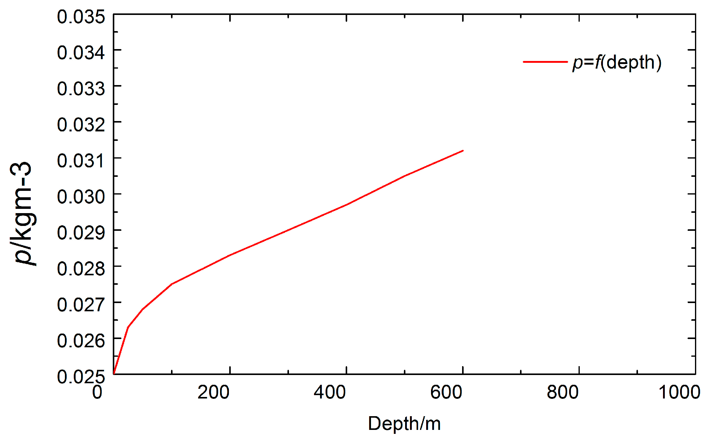
The density, salinity, pressure and temperature of seawater change with diving depth. Deformation of the pressure shell and immersed buoyancy material also bring about changes in the buoyancy of the underwater vehicle. Studies have shown that the buoyancy of an AUV that is neutrally buoyant on the surface will increase by about 5‰ when the AUV dives to a depth of 1000 m because of the increase in the density. The curve of seawater density over depth is shown in Figure 3.
3.2.2. Buoyancy Change Caused by Compressed Pressure Shell
The hydrostatic pressure of the seawater grows as the depth increases. The compressed pressure shell results in reduced displacement of the underwater vehicle. The greater gravity force relative to buoyancy makes the underwater vehicle dive. It is acknowledged that, within the diving depth limit, the reduction in the pressure shell volume is proportional to the pressure imposed. As the underwater vehicle dives from depth (with hydrostatic pressure ) to depth (with hydrostatic pressure ), the buoyancy accordingly changes as in Equation (1).
The variable means the change in buoyancy or the net buoyancy, measured in N or kN. The variable stands for the density of seawater, measured in kg/m3. is the drainage volume of the pressure shell, measured in m3. means the relative reduction value of the pressure shell volume as the pressure increases by one unit, , measured in m2/kg. indicates the diving depth limit of the platform, measured in m. is the hydrostatic pressure at depth , measured in N/m2, the hydrostatic pressure at depth , measured in N/m2.
When the seawater density is assumed to be constant, Equation (2) is expressed as follows:
The variable means the standard atmospheric pressure, measured in N/m2. g is the gravitational acceleration, measured in m/s2.
When Equation (2) is put into Equation (1),
3.2.3. Initial Imbalance between Weight and Buoyancy Forces When Propulsion Ceases
With a balance at a speed, the thruster ceases after the residual rudder angle and trimming angle are eliminated. As the speed approaches zero, the gravity force acting on the underwater vehicle is greater than the buoyancy force that remains when the lift force and moment fall to zero. The gravity is greater than the buoyancy, which is considered as the initial mass imbalance.
3.3. Mathematical Model of Hovering Maneuver
For a well-balanced underwater vehicle during hovering, the balance state will be broken if there are interfering forces. The underwater vehicle will then ascend and descend. At this point, the current passes around the vehicle body with an attack angle of approximately 90°. The hydrodynamic force upon the vehicle body is essentially the cross-flow resistance of the non-streamlined body. Active control must be exercised to keep the underwater vehicle at a given depth. Therefore, with the above simplification and assumptions, a mathematical model of the hovering maneuver can be established as in Equation (4).
The variable is the mass of the underwater vehicle, stands for the density of seawater, the length of the underwater vehicle, the vertical speed and the depth. , and are the drag coefficients in the vertical plane. is the initial imbalance item (namely, the weight–buoyancy force imbalance). The initial imbalance item is the lift force generated by the vehicle body as the speed decreases from a certain speed to zero. is the active control force. In hovering, the thruster stops working, the blades stop rotating and the rudder blade produces no effect. At this point, the active control force is generated by the injection and drainage of water. is the weight–buoyancy imbalance caused by density changes during depth changes. is any external interfering force.
4. Analysis of Influencing Factors of Hovering Control Quality
Whether the depth can be well controlled is closely related to the selection of control parameters, the time to start control and the rate of injection and drainage. A study of how these factors affect the quality of hovering control can optimize the design of the hovering control system and, meanwhile, provide guidance for hovering maneuvers. The aforesaid underwater vehicle and the mathematical model for hovering control were used in this study. Simulation experiments were conducted to find out how these factors influence the quality of hovering control.
4.1. Influence of Control Parameters on Hovering Control
Optimal control theory based on a quadratic performance index was adopted. In this article, we assume that rates of change in the heave direction are small (less than or equal to 0.5 m/s) such that a linearized version of Equation (4) can be used [43]. In this article, the changes of rate in the heave direction are slow (≤0.5 m/s) in the AUV hovering control. Therefore, the system is assumed to be linear. The performance index function is a quadratic function of state variables (output variables) and control variables. The linear system can be described by state equations as follows [43]:
The variable is the n-dimensional state vector and the m-dimensional control vector. is a matrix, and is a matrix. When and are time-invariant matrices, the system is a time-invariant system.
The performance index is shown in Equation (6).
Optimal control aims to have a linear regulator that can minimize the performance target of the system.
Theoretical derivations have proved the optimal control to be unique [43], as shown in Equation (7).
is the optimal state trajectory. The state covariance matrix satisfies the Riccati matrix differential equation as follows [44]:
is the boundary condition.
When , converges to a steady-state solution, , with no relation to . At this point, the Riccati matrix differential equation is regressed to the Riccati matrix algebraic equation, namely,
When making , , gain matrix and the hovering equation of the motion of the underwater vehicle is as follows:
The variable is the state parameter. . is a function of water injection and drainage, . has the same connotation as in Equation (1), namely, it is the net buoyancy or the flow of water injected into or drained from the reservoir.
For a well-balanced hovering underwater vehicle, the initial state is . When external forces exist, the balance state of the underwater vehicle is broken and the preset depth will change. At this point, water should be injected or drained to keep at zero.
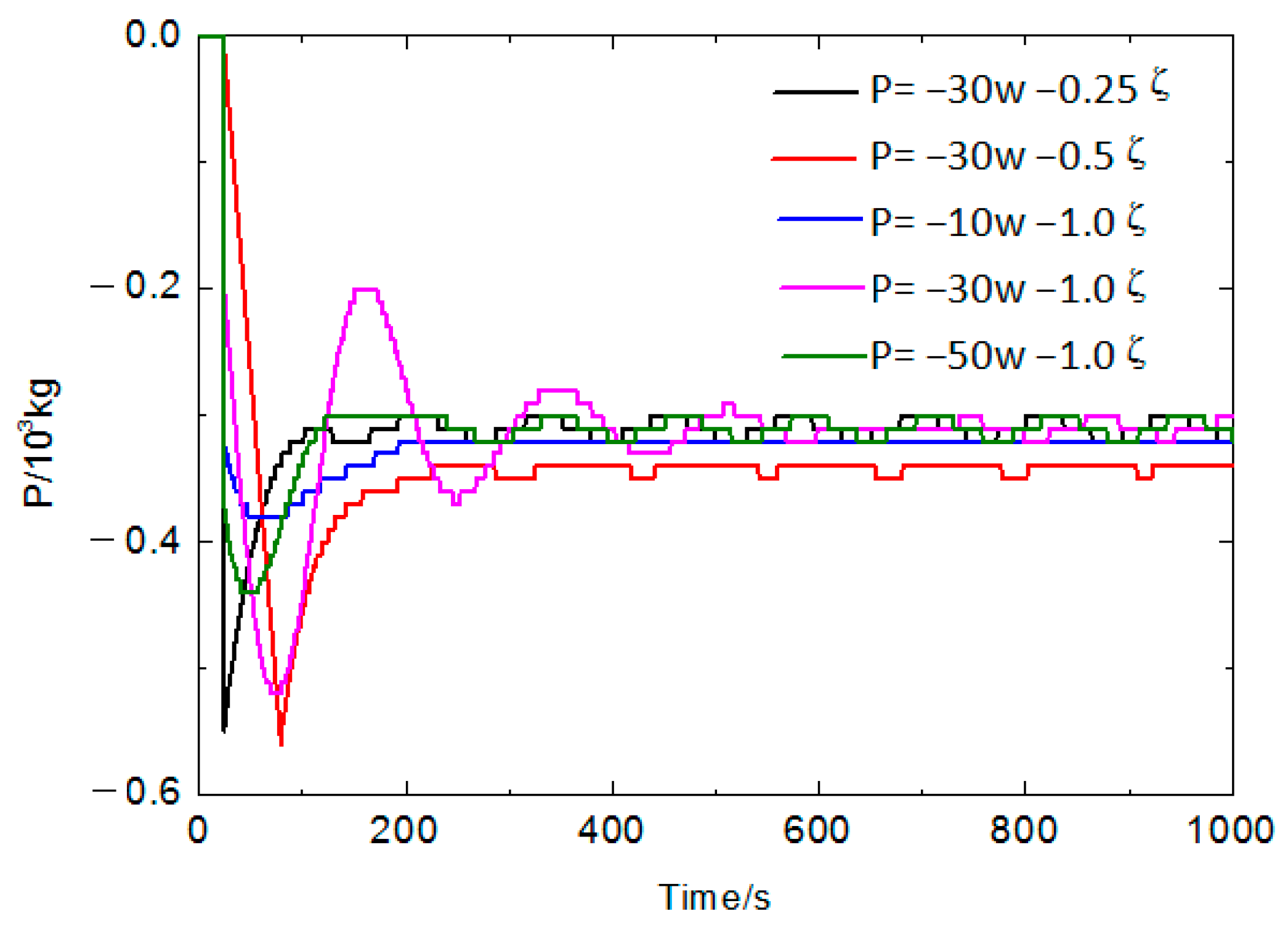
Both PID and PD controllers can realize hovering control that maintains a steady-state error within 0.5 m [45]. At this point, considerations are given to the computer’s calculation ability in selecting the controller. In this article, the steady-state error of hovering control is expected to be within 1 m, which is a relatively less strict requirement. For this reason, the PD control law is adopted to reduce computational load. Based on analysis and comparison, several injection drainage functions were determined with different weight function and gain matrix .
It can be seen from Figure 4 and Figure 5 that the selection of control parameters influenced the stabilization accuracy and oscillation times in the hovering control. Effective control of the vertical velocity was achieved most easily when the rate of water injection was large. The depth value fluctuated mildly, but the water injection volume at each time was large. The coefficient of depth control was small. The depth value fluctuated greatly, but the water injection volume at each time was small. Given the limited volume of the hovering reservoir and limited volume injected or drained at each single time, as well as the modest requirement of depth stabilization accuracy, continuous injection and drainage volume at each single time should be minimized at the time of control parameter selection so as to reduce the demand for resources. The expression is determined to be the best injection and drainage function.
4.2. Influence of Control Timing on Hovering Control
Calculation conditions: initial mass imbalance of 250 kg, injection and drainage speed of 28.8 m3/h, starting trigger for depth control to start operating when the depth disturbance is larger than 0.1 m, 0.5 m and 1.0 m. The calculation results are shown in Figure 6 and Figure 7.
As shown in Figure 6 and Figure 7, the control trigger level had significant influence. A smaller trigger level led to smaller overshoot, smaller volume of injection and drainage and fewer oscillations. Under the above conditions, if the control started with the depth change exceeding 1 m, the fluctuation would exceed 4.0 m. For this reason, the injection and drainage should start as soon as possible at the time of depth change to keep the situation under control before inertia is formed. On the other hand, considering that small depth disturbances may be difficult to observe and would be likely to cause frequent injection and drainage that may result in high energy consumption and noise, the control timing should not be too early. Based on comprehensive considerations, it is appropriate to start the injection and drainage when the depth change exceeds 0.5 m.
4.3. Influence of Injection and Drainage Rate on Hovering Control
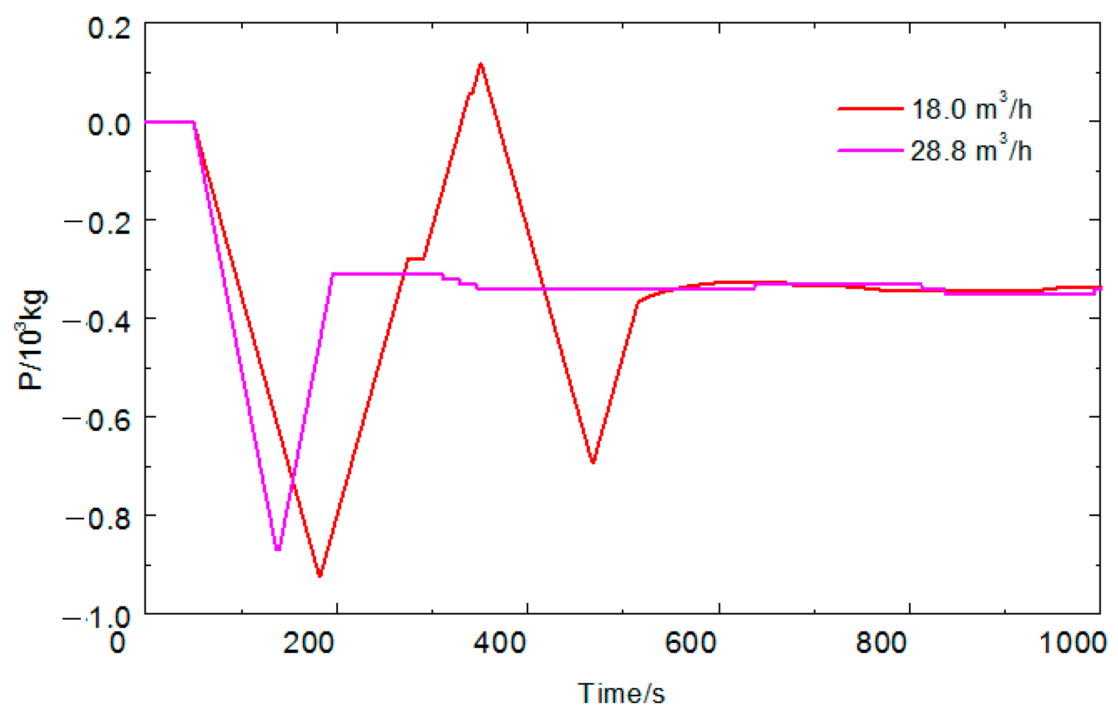
Calculation conditions: initial mass imbalance of 200 kg, injection and drainage speed of 18.0 m3/h and 28.8 m3/h and control starting when the depth excursion exceeds 0.5 m. The calculation results are shown in Figure 8 and Figure 9.
As shown in Figure 8 and Figure 9, higher injection and drainage rate was related to a quicker response and milder depth fluctuations. However, if the injection and drainage rate keeps growing, more resources of the hovering system would be required, together with increased energy consumption and noise. The simulation analysis provides the minimum injection and drainage rate required with different initial imbalance items, as shown in Table 2, for reference in the design of the hovering system.
5. Conclusions
This study on hovering control aims to provide design inputs and maneuver guidance. This study focused on the characteristics of intelligent underwater vehicles during hovering control with the propulsion system shut down, established the mathematical model of hovering control and determined the injection and drainage functions based on the optimal control theory. From the analysis and calculation of the simulation experiments, the influence laws of control parameters, control timing and rate of injection and drainage control upon hovering control were deduced. Therefore, it is proposed that, at the time of control parameter selection, the continuous injection and drainage rate at each time should be reduced as far as possible to relieve the demand on the volume of the reservoir when the requirement of depth control accuracy has been satisfied. In addition, given the limit on the resources and maneuverability of a real underwater vehicle, upon parameter selection, it is proposed that the continuous injection and drainage volume at a single time should be minimized when the requirement of depth stabilization accuracy is satisfied. Moreover, water injection and drainage are recommended to start when the depth change exceeds 0.5 m. Suggestions are also provided on the minimum injection and drainage rate required under different initial mass imbalances. These suggestions are of great guiding importance to the design of the hovering control system and maneuver of real underwater vehicles.
The hovering control method proposed in this article targets AUVs with a main thruster, rudder and hydroplane, but the research findings are also applicable to the over-driven or under-driven AUVs equipped with thrusters only in both large and small size. The control parameters need to be adjusted according to different carriers. The AUVs of different sizes will be studied and discussed in a future study.
Author Contributions
Conceptualization, J.W. and C.J.; methodology, J.W., L.W. and Y.Z.; software, Y.Z. and G.W.; validation, J.W., C.J. and Y.Z.; formal analysis, G.H. and X.C.; investigation, L.W. and G.H.; resources, Y.Z. and J.W.; data curation, J.W., C.J. and G.W.; writing—original draft preparation, J.W.; writing—review and editing, J.W. and C.J.; visualization, X.C. and G.W.; supervision, L.W.; project administration, J.W. and C.J.; funding acquisition, L.W. and G.H. All authors have read and agreed to the published version of the manuscript.
Funding
This research was funded by National Natural Science Foundation of China (grant numbers 51309148, 51779057, 51709061 and 61803119).
Institutional Review Board Statement
Not applicable.
Informed Consent Statement
Not applicable.
Data Availability Statement
The original contributions presented in the study are included in the article, further inquiries can be directed to the corresponding author.
Acknowledgments
We express gratitude to Yushan Sun, Guocheng Zhang, Zhuo Wang, Yueming Li for the support of National Natural Science Foundation of China, and especially Yushan Sun for the help.
Conflicts of Interest
The authors declare no conflicts of interest.
Appendix A
| Symbol | Explanation | Unit |
| Density of seawater | kg/m3 | |
| Drainage volume of the pressure shell | m3 | |
| The relative reduction value of the pressure shell volume as the pressure increases by one unit | m2/kg | |
| Change in buoyancy | N | |
| Hydrostatic pressure | N/m2 | |
| Hlim | Limit diving depth | m |
| Standard atmospheric pressure | N/m2 | |
| g | Gravitational acceleration | m/s2 |
| The mass of the underwater vehicle | kg | |
| The length of the underwater vehicle | m | |
| The vertical speed | m/s | |
| The drag coefficients in the vertical plane | / | |
| The drag coefficients in the vertical plane | / | |
| The drag coefficients in the vertical plane | / | |
| The depth of the underwater vehicle | m | |
| The lift force generated by the vehicle body as the speed decreases from certain speed to zero | N | |
| The active control force | N | |
| The imbalance item of buoyancy caused by density changes during depth changes | N | |
| The external interference force | N |
References
- Walid, R.; Ahmed, C.; Maarja, K. Inverse-model intelligent control of fin-actuated underwater robots based on drag force propulsion. Ocean Eng. 2021, 239, 109883. [Google Scholar]
- Narakorn, S.; Thanongsak, I.; Chirawat, W. Experimental and Computer Simulation Studies on Badminton Racquet Strings. Sensors 2023, 23, 5957. [Google Scholar] [CrossRef] [PubMed]
- Kumar, A.M.; Jyothi, N.A.K.; Dharmendra, S. Information fusion approach for downscaling coarse resolution scatterometer data. Int. J. Image Data Fusion 2023, 14, 89–106. [Google Scholar]
- Rutkowska, D.; Duda, P.; Cao, J.; Rutkowski, L.; Byrski, A.; Jaworski, M.; Tao, D. The L2 convergence of stream data mining algorithms based on probabilistic neural networks. Inf. Sci. 2023, 631, 346–368. [Google Scholar] [CrossRef]
- Mahdi, M.N.; Abbas, R. Parameters optimization of a nonlinear dynamic absorber for a nonlinear system. Arch. Appl. Mech. 2023, 93, 3243–3258. [Google Scholar]
- Ibtisam, M.G.; Ahmed, I.K.; Sajid, S. Can Nonliterates Interact as Easily as Literates with a Virtual Reality System? A Usability Evaluation of VR Interaction Modalities. Systems 2023, 11, 101. [Google Scholar] [CrossRef]
- Natalia, D.; Javier, S.D.; Mark, C. Connecting the dots in trustworthy Artificial Intelligence: From AI principles, ethics, and key requirements to responsible AI systems and regulation. Inf. Fusion 2023, 99, 101896. [Google Scholar]
- Cao, X.; Ashfaq, R.; Cheng, F. A Tumor–on–a–Chip System with Bioprinted Blood and Lymphatic Vessel Pair. Adv. Funct. Mater. 2023, 33, 7408. [Google Scholar] [CrossRef]
- Robinson, C.M.; Popović, Z.; Lasser, G. Linear broadband interference suppression circuit based on GaN monolithic microwave integrated circuits. IET Circuits Devices Syst. 2023, 17, 213–224. [Google Scholar] [CrossRef]
- Virginie, T.; Klaas, W.; Bleuenn, G. Traditional Dimensions of Seabed Resource Management in the Context of Deep Sea Mining in the Pacific: Learning from the Socio-Ecological Interconnectivity between Island Communities and the Ocean Realm. Front. Mar. Sci. 2021, 8, 637938. [Google Scholar]
- Melchers, R.E. Internal corrosion of seabed ‘parked’ steel oil and gas pipelines. Ocean. Eng. 2023, 276, 114145. [Google Scholar] [CrossRef]
- Mike, C. The application of inspection and monitoring in the reduction of risk for mine tailings dams. Proc. Inst. Civ. Eng.-Geotech. Eng. 2022, 175, 142–150. [Google Scholar]
- Karamitrou, A.; Sturt, F.; Bogiatzis, P. Identification of Black Reef Shipwreck Sites Using AI and Satellite Multispectral Imagery. Remote Sens. 2023, 15, 2030. [Google Scholar] [CrossRef]
- Nikolaos, M.; Yiannis, T. GIS-Based Optimal Route Selection of Submarine Cables Considering Potential Seismic Fault Zones. Appl. Sci. 2023, 13, 2995. [Google Scholar] [CrossRef]
- Zhang, T.Q.; Fan, Z.X.; Ning, N.; Tang, J.Z.; Kou, D.X. Analysis of Engineering and Geological Conditions of International Submarine Optical Fiber Cable Routing in the East China Sea Section. Geofluids 2022, 2022, 2527979. [Google Scholar] [CrossRef]
- Khutornaia, E.; Gnevashev, Y. Development of an Application for Controlling an Underwater Vehicle. Transp. Res. Procedia 2023, 68, 858–862. [Google Scholar] [CrossRef]
- Tholen, C.; El-Mihoub, T.A.; Nolle, L.; Zielinski, O. Artificial Intelligence Search Strategies for Autonomous Underwater Vehicles Applied for Submarine Groundwater Discharge Site Investigation. J. Mar. Sci. Eng. 2021, 10, 7. [Google Scholar] [CrossRef]
- Li, Y.F.; Wang, B.; Li, Y.; Liu, Z.Y.; Huo, W.; Li, Y.M.; Cao, J. Underwater object tracker: UOSTrack for marine organism grasping of underwater vehicles. Ocean Eng. 2023, 285, 115449. [Google Scholar] [CrossRef]
- Tomasz, P. Neural control system for a swarm of autonomous underwater vehicles. Knowl.-Based Syst. 2023, 276, 110783. [Google Scholar]
- Madanipour, V.; Najafi, F. Modal analysis of underwater hull cleaning robot considering environmental interaction. Ocean Eng. 2023, 273, 113821. [Google Scholar] [CrossRef]
- Naderolasli, A.; Shojaei, K.; Chatraei, A. Platoon formation control of autonomous underwater vehicles under LOS range and orientation angles constraints. Ocean Eng. 2023, 271, 113674. [Google Scholar] [CrossRef]
- Jin, S.; Bak, J.; Kim, J.; Seo, T.W.; Kim, H.S. Switching PD-Based Sliding Mode Control for Hovering of a Tilting-Thruster Underwater Robot. PLoS ONE 2018, 13, e0194427. [Google Scholar] [CrossRef] [PubMed]
- Salumäe, T.; Chemori, A.; Kruusmaa, M. Motion Control of a Hovering Biomimetic Four-Fin Underwater Robot. IEEE J. Ocean Eng. 2019, 44, 54–71. [Google Scholar] [CrossRef]
- Hong, S.H.; Chung, D.H.; Kim, J.W.; Kim, Y.J.; Kim, A.; Yoon, H.K. In–water visual ship hull inspection using a hover–capable underwater vehicle with stereo vision. J. Field Robot. 2019, 36, 531–546. [Google Scholar] [CrossRef]
- Bak, J.; Moon, Y.; Kim, J.W.; Mohan, S.; Seo, T.W.; Jin, S.R. Hovering control of an underwater robot with tilting thrusters using the decomposition and compensation method based on a redundant actuation model. Robot. Auton. Syst. 2022, 150, 103995. [Google Scholar] [CrossRef]
- Przybylski Michał. Selection of the Depth Controller for the Biomimetic Underwater Vehicle. Electronics 2023, 12, 1469. [Google Scholar] [CrossRef]
- Rosendo, J.L.; Clement, B.; Garelli, F. Experimental validation of constraint mitigation algorithm in underwater robot depth control. Proc. Inst. Mech. Eng. Part I J. Syst. Control Eng. 2019, 233, 264–275. [Google Scholar] [CrossRef]
- He, Y.; Xie, Y.; Pan, G.; Cao, Y.H.; Huang, Q.G.; Ma, S.M.; Zhang, D.L.; Cao, Y. Depth and Heading Control of a Manta Robot Based on S-Plane Control. J. Mar. Sci. Eng. 2022, 10, 1698. [Google Scholar] [CrossRef]
- Davidenko, Y.; Zadorozhnaya, V.H.; Bashkeev, A.; Parshin, A. Semi-Airborne UAV–TEM System Data Inversion with S-Plane Method–Case Study over Lake Baikal. Remote Sens. 2023, 15, 5310. [Google Scholar] [CrossRef]
- Li, J.C.; Chen, P.Y.; Chang, Z.; Zhang, G.B.; Guo, L.J.; Zhao, C.B. Trajectory Tracking Control of Quadrotor Based on Fractional-Order S-Plane Model. Machines 2023, 11, 672. [Google Scholar] [CrossRef]
- Jiang, C.; Lv, J.; Wan, L.; Wang, J.; He, B.; Wu, G. An Improved S-Plane Controller for High-Speed Multi-Purpose AUVs with Situational Static Loads. J. Mar. Sci. Eng. 2023, 11, 646. [Google Scholar] [CrossRef]
- Jiang, C.; Zhang, H.; Wan, L.; Lv, J.; Wang, J.; Tang, J.; Wu, G.; He, B. Design and Verification of Deep Submergence Rescue Vehicle Motion Control System. Sensors 2023, 23, 6772. [Google Scholar] [CrossRef] [PubMed]
- Xiang, B.; Wang, C.Y. The electrostatic levitation system for active suspension control of test sample in horizontal and vertical axes. Sens. Actuators A Phys. 2022, 337, 113404. [Google Scholar] [CrossRef]
- Wang, N.N.; Cai, B.; Chu, X.G.; Su, B.L. Research on suspension control strategy based on finite control set model predictive control with state feedback control-PID for maglev yaw system of wind turbine. IET Electr. Power Appl. 2021, 15, 255–270. [Google Scholar] [CrossRef]
- Cui, G.D.; Cai, B.; Su, B.L.; Chu, X.G. Radial basis function neural network–based adaptive sliding mode suspension control for maglev yaw system of wind turbines. Proc. Inst. Mech. Eng. Part I J. Syst. Control Eng. 2022, 236, 66–75. [Google Scholar] [CrossRef]
- Zou, X.Y.; Jiang, G.H.; Ye, L.C. Underwater Radiated Noise Evaluation and Experimental Analysis of the Support Mother Ship for a Manned Submersible. J. Mar. Sci. Appl. 2022, 22, 343. [Google Scholar] [CrossRef]
- Fang, X.; Liu, F.; Gao, X. Composite Learning Control of Overactuated Manned Submersible Vehicle with Disturbance/Uncertainty and Measurement Noise. IEEE Trans. Neural Netw. Learn. Syst. 2021, 32, 5575–5583. [Google Scholar] [CrossRef] [PubMed]
- Tiwari, K.B.; Sharma, R. Design and Analysis of a Variable Buoyancy System for Efficient Hovering Control of Underwater Vehicles with State Feedback Controller. J. Mar. Sci. Eng. 2020, 8, 263. [Google Scholar] [CrossRef]
- Jin, H.S.; Cho, H.J.; Huang, J.F.; Lee, J.H.; Kim, M.-J.; Jeong, S.-K.; Ji, D.-H.; Joo, K.B.; Jung, D.W.; Choi, H.-S. Hovering control of UUV through underwater object detection based on deep learning. Ocean Eng. 2022, 253, 111321. [Google Scholar] [CrossRef]
- Jyothi, V.B.N.; Ramesh, R.; Vedachalam, N.; Ramadass, G.A. Assessment of the Technological Maturity of Manned Submersible Navigation Positioning Systems. Mar. Technol. Soc. J. 2021, 55, 129–137. [Google Scholar] [CrossRef]
- Kuptsov, V.; Fajri, P.; Rasheduzzaman, M.; Magdaleno-Adame, S.; Hadziristic, K. Combined Propulsion and Levitation Control for Maglev/Hyperloop Systems Utilizing Asymmetric Double-Sided Linear Induction Motors. Machines 2022, 10, 131. [Google Scholar] [CrossRef]
- Nasrollahzadeh, S.; Moghadam, M.B.; Farnoosh, R. A Shewhart-type nonparametric multivariate depth-based control chart for monitoring location. Commun. Stat.-Theory Methods 2023, 52, 7385–7404. [Google Scholar] [CrossRef]
- Joseph, M.; Choi, H.J.; Chen, Y.X.; Umesh, V. Data-driven optimal control via linear transfer operators: A convex approach. Automatica 2022, 150, 110841. [Google Scholar]
- Latreche, T. A Numerical Algorithm for the Resolution of Scalar and Matrix Algebraic Equations Using Runge–Kutta Method. Appl. Comput. Math. 2014, 3, 68–74. [Google Scholar] [CrossRef]
- Wang, R.; Wang, S.; Wang, Y.; Cai, M.X.; Tan, M. Vision-Based Autonomous Hovering for the Biomimetic Underwater Robot—RobCutt-II. IEEE Trans. Ind. Electron. 2019, 66, 8578–8588. [Google Scholar] [CrossRef]
Figure 1.
Platform of AUV.

Figure 2.
Circulating water channel for hydrodynamic test.

Figure 3.
Curve of seawater density over depth.

Figure 4.
Curve of the depth over time under different control parameters.

Figure 5.
Curve of the injection and drainage volume over time under different control parameters.

Figure 6.
Curve of the depth over time with different control trigger levels.

Figure 7.
Curve of the injection and drainage volume over time with different start times.

Figure 8.
Curve of the depth over time under different injection and drainage rates.

Figure 9.
Curve of the injection and drainage volume over time under different injection and drainage rates.
Figure 9.
Curve of the injection and drainage volume over time under different injection and drainage rates.


Table 1.
Parameters of the AUV scale model.
| Parameter | Symbol | Value | Unit |
|---|---|---|---|
| mass | 44.9 | kg | |
| overall length | 1.56 | m | |
| overall breadth | 0.22 | m | |
| overall height | 0.22 | m | |
| vertical coordinate of buoyancy center | 0.000 | m | |
| vertical coordinate of gravity center | 0.018 | m | |
| hovering reservoir volume | 6.2 × 10⁻⁴ | m3 | |
| dimensionless hydrodynamic parameters | −7.0727 × 10⁻² | - | |
| −4.6857 × 10⁻² | - | ||
| −3.1621 × 10⁻² | - |
Table 2.
The minimum injection and drainage rate required under different initial imbalance items.
| Control Element | Initial Mass Imbalance | ||
|---|---|---|---|
| 200 kg | 400 kg | 500 kg | |
| Minimum injection and drainage rate | 18 m3/h | 28.8 m3/h | 39.6 m3/h |
| Maximum depth overshoot | 3.5 m | 4.6 m | 4.5 m |
| Maximum injection and drainage volume at one time | 900 kg | 1200 kg | 1400 kg |
| Fluctuation number | 2 | 3 | 2 |
Disclaimer/Publisher’s Note: The statements, opinions and data contained in all publications are solely those of the individual author(s) and contributor(s) and not of MDPI and/or the editor(s). MDPI and/or the editor(s) disclaim responsibility for any injury to people or property resulting from any ideas, methods, instructions or products referred to in the content. |
© 2024 by the authors. Licensee MDPI, Basel, Switzerland. This article is an open access article distributed under the terms and conditions of the Creative Commons Attribution (CC BY) license (https://creativecommons.org/licenses/by/4.0/).
Share and Cite
MDPI and ACS Style
Wang, J.; Jiang, C.; Wan, L.; Zhou, Y.; Hu, G.; Cheng, X.; Wu, G. Research on the Influencing Factors of AUV Hovering Control in Null-Speed State. J. Mar. Sci. Eng. 2024, 12, 725. https://doi.org/10.3390/jmse12050725
AMA Style
Wang J, Jiang C, Wan L, Zhou Y, Hu G, Cheng X, Wu G. Research on the Influencing Factors of AUV Hovering Control in Null-Speed State. Journal of Marine Science and Engineering. 2024; 12(5):725. https://doi.org/10.3390/jmse12050725
Chicago/Turabian StyleWang, Jianguo, Chunmeng Jiang, Lei Wan, Yimei Zhou, Gangyi Hu, Xide Cheng, and Gongxing Wu. 2024. "Research on the Influencing Factors of AUV Hovering Control in Null-Speed State" Journal of Marine Science and Engineering 12, no. 5: 725. https://doi.org/10.3390/jmse12050725
Note that from the first issue of 2016, this journal uses article numbers instead of page numbers. See further details here.