Article

A Machine Learning Perspective to the Investigation of Surface Integrity of Al/SiC/Gr Composite on EDM

1
Department of Mechanical Engineering, College of Engineering, King Saud University, P.O. Box 800, Riyadh 11421, Saudi Arabia
2
Department of Mechanical Engineering, Maharishi Markandeshwar Engineering College, Maharishi Markandeshwar (Deemed to be Univesity), Mullana 133207, India
3
Mechanical Engineering, Engineering Institute of Technology, Melbourne 3000, Australia
4
Institute for Automation and Applied Informatics, Karlsruhe Institute of Technology, 76344 Eggenstein-Leopoldshafen, Germany
*
Authors to whom correspondence should be addressed.
J. Manuf. Mater. Process. 2023, 7(5), 163; https://doi.org/10.3390/jmmp7050163
Submission received: 15 August 2023 / Revised: 5 September 2023 / Accepted: 6 September 2023 / Published: 8 September 2023
(This article belongs to the Special Issue Smart and Advanced Manufacturing)

Abstract

:
Conventional mechanical machining of composite is a challenging task, and thus, electric discharge machining (EDM) was used for the processing of the developed material. The processing of developed composite using different electrodes on EDM generates different surface characteristics. In the current work, the effect of tool material on the surface characteristics, along with other input parameters, is investigated as per the experimental design. The experimental design followed is an RSM-based Box–Behnken design, and the input parameters in the current research are tool material, current, voltage, pulse-off time, and pulse-on time. Three levels of each parameter are selected, and 46 experiments are conducted. The surface roughness (Ra) is investigated for each experimental setting. The machine learning approach is used for the prediction of surface integrity by different techniques, namely Xgboost, random forest, and decision tree. Out of all the techniques, the Xgboost technique shows maximum accuracy as compared to other techniques. The analysis of variance of the predicted solutions is investigated. The empirical model is developed using RSM and is further solved with the help of a teaching learning-based algorithm (TLBO). The SR value predicted after RSM and integrated approach of RSM-ML-TLBO are 2.51 and 2.47 µm corresponding to Ton: 45 µs; Toff: 73 µs; SV:8V; I: 10A; tool: brass and Ton: 47 µs; Toff: 76 µs; SV:8V; I: 10A; tool: brass, respectively. The surface integrity at the optimized setting reveals the presence of microcracks, globules, deposited lumps, and sub-surface formation due to different amounts of discharge energy.

1. Introduction

The combination of two of more than two components develops a new material, and the selection of the material depends upon the desired characteristics [1]. Due to their distinct characteristics, e.g., light weight and high strength, engineers prefer these materials in ships, aircraft, automobiles, etc. There are a number of ways to develop composite materials, such as stir-casting, powder metallurgy, squeeze casting, etc. The powder metallurgy process is used to develop tungsten carbide bushes. This process is time-effective and associated with zero waste due to near-net shaping. The stir-casting process is used for high volume, where a stirrer is used to stir the molten metal. Then, the molten metal is poured into a cavity to obtain the desired shape [2]. Nowadays, the composite/hybrid composite has gained popularity due to distinctive characteristics, such as better strain resistance, modulus of elasticity, improved thermal conductivity, superior mechanical and tribological characteristics, etc. The matrix can be of any material, namely Al, Mg, Pb, Ni, Ti, etc. Nonetheless, aluminum and its alloys are mostly used as a matrix material for the development of composite/hybrid composites [3]. These aluminum alloys have a vast number of applications in marine/space/aerospace. There are a number of reinforcement particles, such as SiC, B4C, Al2O3, TiC, Si3N4, etc. These are hard, refractory particles incorporated in the matrix material to improve different characteristics. After the incorporation of reinforcements in the matrix material, the strength of materials increases significantly. Due to high strength of composite materials, conventional machining techniques are not used to process them. Therefore, non-traditional machining (NTM) methods are adopted to process composite materials. After the NTM process, there is no need for post-processing due to better surface quality that can be obtained. Also, there is no direct contact between the tool and the workpiece; thus, no residual stresses can be found. There are a number of NTM processes, out of which spark erosion machining processes. Also known as electrical discharge machining (EDM), it is one of the viable options to process hard and conductive material [4].
The EDM is a complex process due to the association of numerous machining indicators. The variation in these indicators varies the output parameters. The input machining indicators include electrode materials [5,6,7,8], dielectric used during machining [9], spark variables (e.g., pulse-on time, pulse-off time, spark gap voltage, current, frequency, etc.) [10], flushing pressure [11], etc. The process parameters play an important role in the intensity of discharge energy [12,13,14]. The performance analysis became an essential step to control the EDM variables. Therefore, after selecting an appropriate parametric combination, the hard-to-machine materials can be processed in an efficient way [15]. An enhancement in the machining rate increases the productivity; however, at the same time, it decreases the surface quality (increase in SR with the increases in crater size). The amplification in the surface quality decreases productivity. Thus, it became mandatory to select an appropriate value of process parameters, where productivity and quality set a compromise. There are a number of responses that may be measured after the machining of work material on EDM. These responses can be listed as cutting rate, material removal rate, surface roughness, dimensional accuracy, etc. A number of hard and conductive material was processed by EDM. These materials include stainless steel, titanium and its alloys, nickel and its alloys, smart materials, composite, etc. [16,17]. A few works conducted by researchers are provided as follows.
Channi et al. [18] developed Al/TiB2 composite and processed it on EDM at different process parameters. The cutting rate and surface roughness were investigated for a developed composite of 5% and 10% reinforcement percentages. The tool wear was 0.2146 and 0.1749 mm3/min, and SR was 2.47 and 3.03 µm for 5% and 10% TiB2 reinforcement, respectively. Shanmugavel et al. [19] investigated the overcut and SR while processing Al-Mg-MoS2 composite on a spark erosion machine. The SR and overcut decreased with the increase in MoS2 percentage. This was attributed to melting point temperature differences at different temperatures.
There are a number of optimization techniques available by which the machining indicators of the EDM process can be optimized. The involvement of a single response deals with the problem as a single-response optimization problem, while the involvement of two or more than two response variables makes the problem a multi-response optimization or a multi-criteria decision-making (MCDM) problem. There are two types of optimization techniques: the first one is statistical, and the second is an artificial intelligence technique. These include Taguchi technique [20,21,22,23], response surface methodology [24,25,26], gray relational analysis [27,28,29], utility concept [30], entropy measurement technique [31,32], genetic algorithm [33], non-dominated genetic algorithm [34,35], particle swarm optimization [36,37], teaching learning-based optimization [25], artificial neural network [38,39], gray wolf optimization [40,41], etc. The above-mentioned techniques are used for the planning of experiments, modeling, and optimization of the machining indicators. In this direction, Chen et al. [42] studied different optimization techniques utilized in EDM processes.
It is clear from the literature that most of the research has been conducted on different hard alloys (Ti, Ni, and its alloys) [43]. There are some works conducted by Peng et al. [44,45] on the wear behavior of Ni and Ti alloys while processing them with conventional machining using a high-pressure coolant supply. In the previous research, the optimization was performed using statistical or artificial intelligence techniques on CR, MRR, dimensional deviation, etc. There is limited research has been published on the processing of Al/SiC/Gr hybrid composite by EDM. Recently, Abbas et al. reported a research study in which Al/SiC/Gr hybrid composite was developed using a stir-casting route, and the composite material was processed on EDM [40]. The authors examined the effect of a number of dominant process parameters on both responses: material removal rate (MRR) and tool wear rate (TWR). As a useful extension of the Abbas et al. study reported in [46], the present research examined the obtainable surface quality when processing Al/SiC/Gr hybrid composite using EDM. The input parameters considered were tool material, pulse-on time, pulse-off time, current, and voltage, while surface integrity is assumed as the response variable. The experiments were planned according to the Box–Behnken design (BBD). The aims of the present work are:
(i)
To find the surface roughness values using different strategies of ML approach.
(ii)
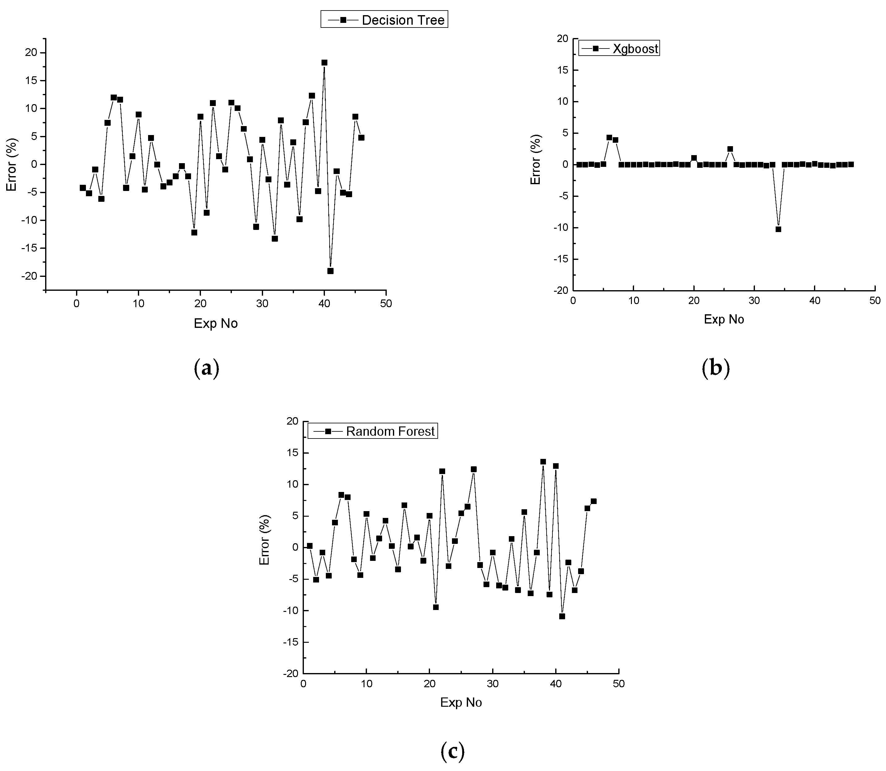
To find out the error percentage between the predicted value by different ML strategies and experimental values.
(iii)
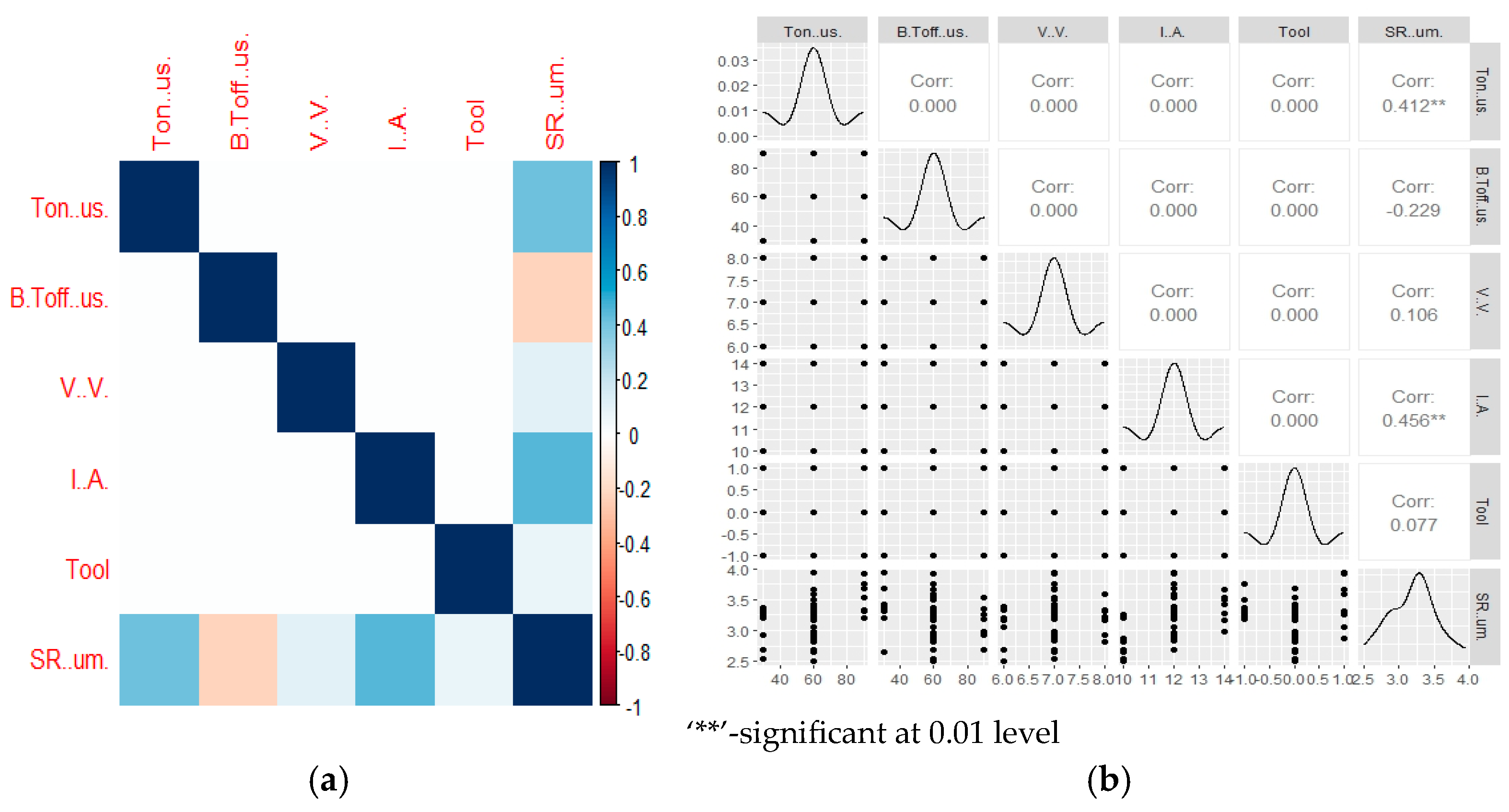
To analyze the response variables with the machining indicators using ANOVA.
(iv)
To optimize the best solutions predicted by the ML approach using TLBO and perform the validation experiments at the suggested setting
(v)
To perform the mapping of elements for different electrodes used for machining along with the morphological analysis of the machined surface of the composite.

2. Materials and Methods

As formerly stated, the aluminum-based metal matrix composite (AMC) was previously developed using a stir-casting process and was further investigated herein. In particular, as reported in [40], the Gr and SiC particles were initially preheated in the oven to eliminate any moisture. Another advantage of preheating the reinforcement particles is to reduce the chances of the development of the Al4C3 phase, which is brittle in nature. The Al-6063 alloy purchased in the form of a bar is cut in the form of small billets and put in the graphite crucible along with the Gr and SiC. Due to the SiC, a reaction with the Al alloy occurs, which forms a layer and prevents the brittle phase. The graphite present increases the wettability. The factors influencing different characteristics of AMC are reinforcement shape, size, and volume fraction. These composites show two phases, which are Al and Gr and Al and SiC. Out of these two phases, the bond of SiC and Al is much more robust than the bond of Gr and Al.

2.1. Experimental Set-Up

Again, as previously reported in [40], the die-sinking EDM (Oscar Max make, Taichung City, Taiwan) was used for the processing of developed AMC using different electrode materials (steel-304, brass, and copper). A preliminary study has been conducted to identify five significant machining variables. The levels, units, and notations for each parameter are provided in Table 1 [40].
As tool material is qualitative in nature and cannot be considered in the experimental design, we provided codes to different electrodes in the experimental design. The diameter of each electrode was 12 mm, and a commercial-grade dielectric was used in the EDM. Figure 1 shows the process flow diagram used in the current work.

2.2. Response Characterization

In the present work, average surface roughness is recorded using Mitutoyo make surface roughness tester (SJ-201P) having a minimum measurement of 0.01 µm. Before the evaluation, the surface (machined) is cleaned with acetone. There are two faces on the machined surface; one is parallel to the traveling wire, and another is perpendicular to the traveling wire. The measurement of Ra is made perpendicular to the traveling wire. The mean of three readings is chosen in the analysis.

2.3. Methodology

The experiments were planned as per BBD of RSM [47]. There are five process parameters with three levels each. There are 46 experiments at different settings of input machining indicators as per the run order. There are a few similar experimental settings where the process parameters exhibit the same values. Nevertheless, these similar experimental settings are distributed randomly to check the stability of the machine tool by providing the Ra values, which have a close relationship. The process involved in the implementation of RSM is (i) designing experiments considering the process parameters and their levels, (ii) analysis of results using statistical summary, and (iii) development of the mathematical model. The mathematical model is also developed, which makes an objective function in relation to the input parameters. Equation (3) provides the mathematical model
R a = f R 1 , R 2 , R 3 , R 4 , R 5
where ‘Ra’ is the surface roughness and ‘f’ is the objective function, which is formed with input variables (R1: pulse-on time; R2: tool; R3: voltage; R4: pulse-off time; and R5: current).
The experimental results obtained after performing the experiments as per the design layout will be used to train the program for the implementation of machine learning (ML). Three different machine learning strategies (namely decision tree, booster, and random forest) were implemented on the experimental data. The results obtained and error percentage in all three methods were compared to obtain the best ML strategy. On the predicted solution obtained from the best strategy, the RSM method is applied to obtain the mathematical model. The obtained mathematical model is further solved using teaching learning-based optimization (TLBO).

3. Results and Discussion

The SR values obtained in 46 experimental runs are presented in Table 2, considering the randomness.

3.1. Machine Learning Perspective

The experimental data obtained from different experiments are used for training and testing purposes in the ML approach. Three different strategies are used for this decision tree, boosting, and random forest. In the decision tree method, the conditional steps are considered for the evaluation of responses, while in random forest, the collective intelligence is considered. This collective intelligence increases the capacity of the algorithm by selecting multiple things together. The gradient boost increases the capacity by the addition of decision trees, i.e., one decision tree is added one after the other. Table 3 provides the experimental values and the SR values predicted from three different strategies.
Figure 2 provides the comparison of experimental SR and the predicted SR values evaluated from three different strategies. It is clear from Figure 2a–c that the predicted values obtained from the gradient boost plan cover most of the experimental values. The black lines show the experimental values of SR, and the red line depicts the predicted values. In Figure 2a,c, there are some differences in the predicted and experimental values. Nonetheless, in Figure 2b, i.e., grading boost ML approach, the predicted values of SR are very close to experimental values. Figure 2d shows the combined results of experimental and predicted SR using different ML approaches.
Figure 3 depicts the error percentage in all three cases, namely decision tree (Figure 3a), gradient boost (Figure 3b), and random forest (Figure 3c). It is clear from the error percentage plot that minimum error is observed for the gradient boost algorithm. All the values predicted by the gradient boost method show an error in the range of ±1% except six predictions. However, those six predictions exhibit an error percentage of less than ±10%. However, from the decision tree algorithm (Figure 3a) and random forest (Figure 3c), the error percentage is more than ±10%.

3.2. Analysis of Results Evaluated from Gradient Boost Algorithm and TLBO Implementation

After the investigation of predictive values of SR after all the ML strategies, it is clear that the best method for the prediction of solutions while processing Al/SiC/Gr on WEDM is the gradient boost algorithm. This is clear from the prediction of the solution (Figure 2b) and error percentage calculation (Figure 3b) that the results of SR have close agreement with experimental values with minimum error. Further, the analysis was made on the data obtained from the gradient boost algorithm.
Figure 4a depicts the normality plot of the residual, and it is observed that all the residual lies on a straight line, which is desired for a suitable ANOVA. Figure 4b presents the plots for residual versus predicted, and as required for a sign of suitable ANOVA, all the residuals were not clustered. These should be randomly distributed, as in Figure 4b. The perturbation plot is represented in Figure 4c, which depicts the significance of each machining variable on response depending upon the slope of each parameter. From Figure 4c, current (D) has a maximum slope, followed by Ton (A), Toff (B), and tool (E). The cube plot (Figure 4d) gives the variation in SR with all significant parameters. From Figure 2d, keeping Toff constant at 30 µs, current at 10 A; if Ton is increased from 30 µs to 90 µs, the SR values increase from 2.95 µm to 3.42 µm. Similarly, SR from a cube plot can be studied by keeping two input parameters constant and varying the third input parameter.
The statistical summary is presented by ANOVA in Table 4. This summary presents that ‘I’ has the maximum contribution to the investigation of SR, preceded by Ton and Toff. The quadratic term of Ton, Toff, and tool material also has a significant contribution to the evaluation of SR. These are considered due to the p-value of less than 0.05, which makes it a significant model. However, one point worth noting is that tool material has a p-value equal to 0.332, which is greater than 0.05. But, this term is forcefully incorporated in the model. This occurs due to the quadratic term of tool material, which is significant. If tool is removed during the analysis, the significant term (quadratic of tool) is also removed. Therefore, tool is forcefully considered for the evaluation. Equation (2) is the empirical model developed for SR values.
SR = +2.70439 − 0.023556 × Ton − 0.024123 × Toff + 0.12973 × I + 0.043882 × Tool + 2.61338 × 10⁻⁴ × Ton2 + 1.64755 × 10⁻⁴ × Toff2 + 0.37596 × Tool2
The ML approach has been implemented to identify the correlation between the input parameters and SR. The data provided in Table 3 are used for training (70% data) and testing (30% data) purposes. The different parameters are varied in machine learning to find out the best solution. The definition of the best solution here is the minimum error with maximum accuracy. The following parameters in (R software-4.2.3) were selected for the identification of the best solution.
parameters <- list(eta = 0.3,
max_depth = 6,
subsample = 1,
colsample_bytree = 1,
min_child_weight = 1,
gamma = 0,
eval_metric = “rmse”,
booster = “gbtree”)
The main Function used for ML approach is given below:
model1 <- xgboost::xgboost(data = train_features,
label = train_label,
set.seed (1234),
nthread = 6,
nround = 1000,
params = parameters,
print_every_n = 50,
early_stopping_rounds = 20,
verbose = 1)
Figure 5 shows the correlation plot between the machining indicators and SR. It is clear from the plot (Figure 5a) that color defines the correlation. Dark blue color shows the maximum positive (+1) correlation, and dark brown color depicts the minimum negative (−1) correlation. A positive correlation means the SR value increases with the increase in machining variables. However, a negative correlation means SR decreases with the increase in machining variables. Figure 5b shows the correlation plot according to their values. It has been observed that a maximum correlation exists between current and SR with a correlation value of 0.456. After that, a 0.412 correlation value was observed in the case of Ton. The negative value of correlation (−0.229) exists in the case of SR and Toff, which means that with the surge in Toff value, the SR value decreases.
Figure 6 depicts the variation in SR value with respect to the number of iterations. Initially, the SR is high due to the large population, but with the enhancement in iterations, the SR value decreases, and the best solution is obtained, which is 2.4696 µm.
Table 5 shows the comparison of the confirmation experiments corresponding to the suggested optimized setting of the machining indicators. The optimized setting suggested by RSM and RSM-ML-TLBO are compared with the best value of SR (Exp. No. 38) investigated experimentally from the experimental array. The suggested solutions from both techniques are provided in Table 5. The input parameters are suggested in decimal points. Therefore, during the confirmation experiments, the process parameters value was selected in a feasible way (near integer value of process parameters). The asterisk (*) corresponding to V depicts that this parameter is non-significant. Thus, the empirical model in Equation (2) does not contain the ‘V’ parameter, and hence, the suggested solution of the RSM-ML-TLBO approach does not have any ‘V’ value. During the confirmation experiments, ‘V’ is set at 8V, and the experiments are conducted. The best SR value is obtained in the case of the RSM-ML-TLBO approach. Therefore, the suggested approach is effectively used for the optimization of EDM parameters while machining Al/SiC/Gr hybrid composite.

4. Morphological Study

The morphological study of the workpiece and tool materials is conducted in this section, as three different types of electrodes are used in the present work. Therefore, the EDS plot, microstructure, and mapping of elements are provided.
Figure 7 depicts the observation for the SS-304 tool material. Figure 7a shows the EDS plot, and it is clear from the plot that peaks of Fe, Ni, Cr, and Si are observed. The area of material where the EDS plot and elemental mapping were performed is provided in Figure 7b. The combined results of elements are captured in Figure 7c, where the presence of C, O, Fe, and Cr are made. Figure 7d,g shows the mapping for carbon, oxygen, ferrous, and chromium, respectively.
Figure 8 presents the data related to the aluminum material used as an electrode during the processing of Al/SiC/Gr composite. Figure 8a provides the EDS plot, which verifies the presence of aluminum with a peak of it. Other confirmed elements in the material are carbon, oxygen, sodium, silicon, and calcium. The microstructure captured for the analysis of elements is provided in Figure 8b. The elemental mapping of all the elements present in the material is shown in Figure 8c. However, the mapping of individual elements is provided in Figure 8d (carbon), Figure 8e (oxygen), Figure 8f (sodium), Figure 8g (aluminum), Figure 8h (silicon), and Figure 8i (calcium). As this is the elemental mapping of aluminum, Figure 7g shows a great volume of aluminum.
The images captured and their analysis for the brass electrode are provided in Figure 9. The peaks of copper and zinc in Figure 9a verify the brass alloy. The elemental mapping of the brass electrode is made on the area shown in Figure 9b, and the combined results of mapping are shown in Figure 9c. The individual mapping of each element is shown in Figure 9d–g (i.e., for carbon (Figure 9d), oxygen (Figure 9e), copper (Figure 9f), and zinc (Figure 9g)).
Figure 7b, Figure 8b and Figure 9b show the morphology of the SS, Al, and brass after machining. It has been observed that the SS surface exhibits minimum irregularities as compared to Al and brass. The surface of Al shows lumps, cracks, and craters. However, using SS, the lumps are reduced significantly. The main reason is the melting temperature of these alloys, which are SS: ~1430°C; Al: 660 °C; brass: 930 °C. The lower the melting point of the material, the higher will be the surface irregularities. The morphology of the machined surface is analyzed using an SEM micrograph. The discharge energy (DE) between the workpiece and tool is the main source of material removal from the work material. The level of DE depends upon the values of the input parameters. The high value of Ton and current improves the DE in the circuit, while the high value of Toff and SV decreases the DE. Therefore, SEM micrographs are captured at different settings of machining indicators. Figure 10a shows the micrograph of the machined surface for experiment number 41, i.e., Ton: 60 µs; Toff: 30 µs; SV:7V; I: 12; tool: brass. Here, the Ton value is maximum, Toff is minimum, SV is minimum, and current is maximum with brass electrode, which develops maximum DE. The maximum DE in the circuit removes the maximum amount of material in the form of craters. Therefore, maximum DE energy parameters generate maximum surface irregularities (uneven surface), which presents maximum SR. The DE can be calculated using Equation (3).
D E = 0 t d V d ( t ) × I ( t ) × d t     V d I t d  
where I: discharge current; Vd: discharge voltage; td: discharge time. The value of current and voltage is provided; however, for the discharge time, the delay time is assumed as zero. Thus, the time becomes equal to the Ton. From Figure 10a, deposited lumps are detected due to the rapid heating and cooling. With the start of the circuit, the temperature in the circuit increases, which melts the material. At the same time, dielectric comes into play, and some of the molten material is deposited in the form of lumps, and some of the material is deposited in the form of debris. The main reason for the microcracks in the EDM process is the development of thermal stresses, which develop during the thermal gradient on the machined surface. Figure 10b shows a significant reduction in the surface irregularities. This is due to the combination of process parameters (Ton: 60 µs; Toff: 60 µs; SV:6 V; I: 10 A; tool: copper) on which the material is machined. As compared to experiment number 41, in the present experiment number (38), the Toff value is increased, SV is decreased, and current is decreased. Hence, the level of DE at this parametric setting is decreased, due to which the crater size decreases and improves the surface quality (2.51 µm).
Figure 10c shows an SEM micrograph of the machined surface of Al/SiC/Gr hybrid composite at Ton: 60 µs; Toff: 30 µs; SV:8 V; I: 12 A; tool: copper. At this parametric setting, DE is increased from the DE level at experiment number 38 due to the high value of current. In this setting, microcracks, sub-surface formation, uneven surfaces, and deposited lumps are observed. The amount of these irregularities is more than experiment number 38 and less than experiment number 41. Figure 10d depicts the captured SEM micrograph of a hybrid composite, which is machined at parametric setting Ton: 60 µs; Toff: 90 µs; SV:7 V; I: 14 A; tool: copper. At the optimized setting, Ton: 47 µs; Toff: 76 µs; SV:8V; I: 10 A; tool: brass; the surface morphology is depicted in Figure 10e. It is clear from Figure 10e that the unevenness of the surface is reduced very much as compared to other SEM images (from Figure 10a–d). This is due to low DE level parameters, by which small-size craters are removed and SR is decreased.

5. Conclusions

The SR and surface integrity of Al/SiC/Gr hybrid composite are identified at different parametric settings of the EDM process with the objective of predicting solutions using different strategies of ML. The optimization was performed on the best predicted solution set using TLBO, and the below-mentioned observations are drawn from the present research:
(i)
The best ML strategy for the prediction of SR while processing Al/SiC/Gr hybrid composite on EDM is gradient boost, which exhibits an error percentage in the range of ±1% (except for six observations).
(ii)
The discharge current has a significant influence on SR, followed by Ton and Toff. However, tool material is hierarchically added in the quadratic model.
(iii)
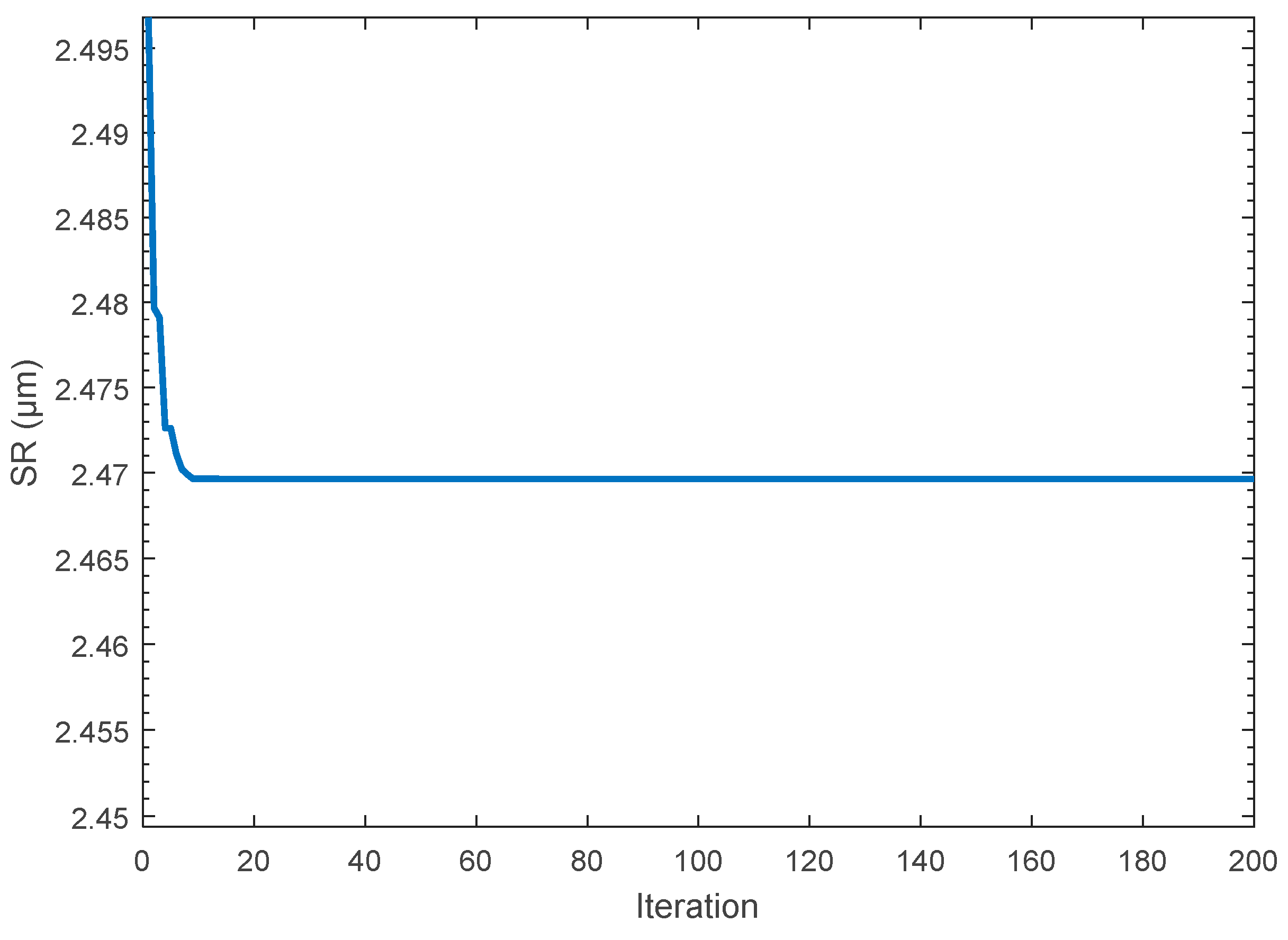
The best SR value after the RSM and integrated approach of RSM-ML-TLBO are 2.51 and 2.47 µm corresponding to Ton: 45 µs; Toff: 73 µs; SV:8 V; I: 10 A; tool: brass and Ton: 47 µs; Toff: 76 µs; SV:8V; I: 10A; tool: brass, respectively.
(iv)
At high DE level parameters, the DE is large between the tool and workpiece, and a large number of microcracks, deposited lumps, sub-surface formation, etc., are observed. However, the deposited lumps, microcracks, and uneven surfaces are significantly reduced from the machined surface, which is processed at the optimized settings suggested by RSM-ML-TLBO.

Author Contributions

A.T.A.: funding acquisition; A.T.A., N.S. and E.A.A.-B.: visualization, validation, data curation, methodology, conceptualization, investigation; A.E., I.F. and V.S.S.: review and editing; project administration; supervision; conceptualization; writing—original draft, writing. All authors have read and agreed to the published version of the manuscript.

Funding

King Saud University. Project number (RSPD2023R1064).

Data Availability Statement

Not applicable.

Acknowledgments

The authors extend their appreciation to King Saud University for funding this work through Researchers Supporting Project number (RSPD2023R1064), King Saud University, Riyadh, Saudi Arabia.

Conflicts of Interest

The authors declare no conflict of interest.

References

  1. Baratzadeh, F.; Handyside, A.B.; Boldsaikhan, E.; Lankarani, H.; Carlson, B.; Burford, D. Microstructural and Mechanical Properties of Friction Stir Welding Joints of 6082-T6 with 6063-T6. In Friction Stir Welding and Processing VI; John Wiley & Sons: Hoboken, NJ, USA, 2011; pp. 229–236. [Google Scholar]
  2. Kumar, S.; Pandey, R.; Panwar, R.S.; Pandey, O.P. Effect of Particle Size on Wear of Particulate Reinforced Aluminum Alloy Composites at Elevated Temperatures. J. Mater. Eng. Perform. 2013, 22, 3550–3560. [Google Scholar] [CrossRef]
  3. Kumar, N.; Ahuja, N.; Singh, S. Review of Research Work in Wire-Cut Electrical Discharge Machining (WEDM). Int. J. Eng. Studies. 2014, 6, 224–230. [Google Scholar]
  4. Davim, J.P.; Jain, V.K. Advanced (Non-Traditional) Machining Processes. In Machining; Fundamentals and Recent Advances; Springer: London, UK, 2008; pp. 299–327. [Google Scholar]
  5. Mohanty, C.P.; Satpathy, M.P.; Mahapatra, S.S.; Singh, M.R. Optimization of Cryo-Treated EDM Variables Using TOPSIS-Based TLBO Algorithm. Sādhanā 2018, 43, 51. [Google Scholar] [CrossRef]
  6. Mohanty, C.P.; Mahapatra, S.S.; Singh, M.R. An Intelligent Approach to Optimize the EDM Process Parameters Using Utility Concept and QPSO Algorithm. Eng. Sci. Technol. Int. J. 2017, 20, 552–562. [Google Scholar] [CrossRef]
  7. Lee, S.H.; Li, X.P. Study of the Effect of Machining Parameters on the Machining Characteristics in Electrical Discharge Machining of Tungsten Carbide. J. Mater. Process. Technol. 2001, 115, 344–358. [Google Scholar] [CrossRef]
  8. Bhaumik, M.; Maity, K. Effect of Different Tool Materials during EDM Performance of Titanium Grade 6 Alloy. Eng. Sci. Technol. Int. J. 2018, 21, 507–516. [Google Scholar] [CrossRef]
  9. Kanagarajan, D.; Karthikeyan, R.; Palanikumar, K.; Sivaraj, P. Influence of Process Parameters on Electric Discharge Machining of WC/30% Co Composites. Proc. Inst. Mech. Eng. Part B J. Eng. Manuf. 2008, 222, 807–815. [Google Scholar] [CrossRef]
  10. Theisen, W.; Schuermann, A. Electro Discharge Machining of Nickel–Titanium Shape Memory Alloys. Mater. Sci. Eng. A 2004, 378, 200–204. [Google Scholar] [CrossRef]
  11. Wang, S.M.; Wu, J.X.; Gunawan, H.; Tu, R.Q. Optimization of machining parameters for corner accuracy improvement for WEDM processing. Appl. Sci. 2022, 12, 10324. [Google Scholar] [CrossRef]
  12. Peta, K.; Mendak, M.; Bartkowiak, T. Discharge Energy as a Key Contributing Factor Determining Microgeometry of Aluminum Samples Created by Electrical Discharge Machining. Crystals 2021, 11, 1371. [Google Scholar] [CrossRef]
  13. Gostimirovic, M.; Kovac, P.; Sekulic, M.; Skoric, B. Influence of Discharge Energy on Machining Characteristics in EDM. J. Mech. Sci. Technol. 2012, 26, 173–179. [Google Scholar] [CrossRef]
  14. Salcedo, A.T.; Arbizu, I.P.; Pérez, C.J.L. Analytical Modelling of Energy Density and Optimization of the EDM Machining Parameters of Inconel 600. Metals 2017, 7, 166. [Google Scholar] [CrossRef]
  15. Singh, V.; Sharma, A.K.; Goyal, A.; Kumar Saxena, K.; Negi, P.; Rao, P.C.S. Electric Discharge Machining Performance Measures and Optimisation: A Review. Adv. Mater. Process. Technol. 2023, 1–14. [Google Scholar] [CrossRef]
  16. Hasan, M.M.; Saleh, T.; Sophian, A.; Rahman, M.A.; Huang, T.; Mohamed Ali, M.S. Experimental Modeling Techniques in Electrical Discharge Machining (EDM): A Review. Int. J. Adv. Manuf. Technol. 2023, 127, 2125–2150. [Google Scholar] [CrossRef]
  17. Ming, W.; Zhang, S.; Zhang, G.; Du, J.; Ma, J.; He, W.; Cao, C.; Liu, K. Progress in Modeling of Electrical Discharge Machining Process. Int. J. Heat Mass Transf. 2022, 187, 122563. [Google Scholar] [CrossRef]
  18. Channi, A.S.; Bains, H.S.; Grewal, J.S.; Chidambranathan, V.S.; Kumar, R. Tool Wear Rate during Electrical Discharge Machining for Aluminium Metal Matrix Composite Prepared by Squeeze Casting: A Prospect as a Biomaterial. J. Electrochem. Sci. Eng. 2023, 13, 149–162. [Google Scholar]
  19. Shanmugavel, R.; Chinthakndi, N.; Selvam, M.; Madasamy, N.; Shanmugakani, S.K.; Nair, A.; Prakash, C.; Buddhi, D.; Dixit, S. Al-Mg-MoS2 Reinforced Metal Matrix Composites: Machinability Characteristics. Materials 2022, 15, 4548. [Google Scholar] [CrossRef]
  20. Lin, M.-Y.; Tsao, C.; Hsu, C.; Chiou, A.; Huang, P.; Lin, Y. Optimization of Micro Milling Electrical Discharge Machining of Inconel 718 by Grey-Taguchi Method. Trans. Nonferrous Met. Soc. China 2013, 23, 661–666. [Google Scholar] [CrossRef]
  21. Nikalje, A.M.; Kumar, A.; Srinadh, K.V. Influence of Parameters and Optimization of EDM Performance Measures on MDN 300 Steel Using Taguchi Method. Int. J. Adv. Manuf. Technol. 2013, 69, 41–49. [Google Scholar] [CrossRef]
  22. Kalsi, N.S.; Sehgal, R.; Sharma, V.S. Multi-Objective Optimization Using Grey Relational Taguchi Analysis in Machining: Grey Relational Taguchi Analysis. Int. J. Organ. Collect. Intell. 2016, 6, 45–64. [Google Scholar] [CrossRef]
  23. Jangra, K.; Grover, S.; Aggarwal, A. Simultaneous Optimization of Material Removal Rate and Surface Roughness for WEDM of WC-Co Composite Using Grey Relational Analysis along with Taguchi Method. Int. J. Ind. Eng. Comput. 2011, 2, 479–490. [Google Scholar] [CrossRef]
  24. Kumar, A.; Singh, H.; Kumar, V. Study the parametric effect of abrasive water jet machining on surface roughness of Inconel 718 using RSM-BBD techniques. Mater. Manuf. Process. 2018, 33, 1483–1490. [Google Scholar] [CrossRef]
  25. Kumar, A.; Sharma, R.; Gujral, R. Investigation of crack density, white layer thickness, and material characterization of biocompatible material commercially pure titanium (grade-2) through a wire electric discharge machining process using a response surface methodology. J. Process Mech. Eng. 2021, 235, 2073–2097. [Google Scholar] [CrossRef]
  26. Kumar, A.; Singh, R.; Sharma, R. Investigation of machining characterization of solar material on WEDM process through response surface methodology. J. Mech. Behav. Mater. 2023, 32, 20220291. [Google Scholar] [CrossRef]
  27. Ahuja, N.; Batra, U.; Kumar, K. Multicharacteristics optimization of electrical discharge micro hole drilling in Mg alloy using hybrid approach of GRA–regression–PSO. Grey Sys. Theory Appl. 2021, 11, 136–151. [Google Scholar] [CrossRef]
  28. Khanna, R.; Kumar, A.; Garg, M.P.; Singh, A.; Sharma, N. Multiple Performance Characteristics Optimization for Al 7075 on Electric Discharge Drilling by Taguchi Grey Relational Theory. J. Ind. Eng. Int. 2015, 11, 459–472. [Google Scholar] [CrossRef]
  29. Selvarajan, L.; Manohar, M.; Dhinakaran, P. Modelling and Experimental Investigation of Process Parameters in EDM of Si3N4-TiN Composites Using GRA-RSM. J. Mech. Sci. Technol. 2017, 31, 111–122. [Google Scholar] [CrossRef]
  30. Kumar, P.; Barua, P.B.; Gaindhar, J.L. Quality Optimization (Multi-characteristics) through Taguchi’s Technique and Utility Concept. Qual. Reliab. Eng. Int. 2000, 16, 475–485. [Google Scholar] [CrossRef]
  31. Jangra, K.K.; Sharma, N.; Khanna, R.; Matta, D. An Experimental Investigation and Optimization of Friction Stir Welding Process for AA6082 T6 (Cryogenic Treated and Untreated) Using an Integrated Approach of Taguchi, Grey Relational Analysis and Entropy Method. Proc. Inst. Mech. Eng. Part L J. Mater. Des. Appl. 2016, 230, 454–469. [Google Scholar] [CrossRef]
  32. Jangra, K.; Grover, S.; Aggarwal, A. Optimization of Multi Machining Characteristics in WEDM of WC-5.3% Co Composite Using Integrated Approach of Taguchi, GRA and Entropy Method. Front. Mech. Eng. 2012, 7, 288–299. [Google Scholar] [CrossRef]
  33. Sharma, V.; Misra, J.P.; Singhal, S. Machine Learning Algorithms Based Advanced Optimization of Wire-EDM Parameters: An Experimental Investigation into Titanium Alloy. Int. J. Interact. Des. Manuf. 2023, 1–14. [Google Scholar] [CrossRef]
  34. Kalita, K.; Ghadai, R.K.; Chakraborty, S. A Comparative Study on Multi-Objective Pareto Optimization of WEDM Process Using Nature-Inspired Metaheuristic Algorithms. Int. J. Interact. Des. Manuf. 2023, 17, 499–516. [Google Scholar] [CrossRef]
  35. Garg, M.P.; Jain, A.; Bhushan, G. Modelling and multi-objective optimization of process parameters of wire electrical discharge machining using non-dominated sorting genetic algorithm-II. J. Eng. Manuf. 2012, 226, 1986–2001. [Google Scholar] [CrossRef]
  36. Saffaran, A.; Azadi Moghaddam, M.; Kolahan, F. Optimization of Backpropagation Neural Network-Based Models in EDM Process Using Particle Swarm Optimization and Simulated Annealing Algorithms. J. Braz. Soc. Mech. Sci. Eng. 2020, 42, 73. [Google Scholar] [CrossRef]
  37. Nain, S.S.; Garg, D.; Kumar, S. Investigation for Obtaining the Optimal Solution for Improving the Performance of WEDM of Super Alloy Udimet-L605 Using Particle Swarm Optimization. Eng. Sci. Technol. Int. J. 2018, 21, 261–273. [Google Scholar] [CrossRef]
  38. Singh, B.; Misra, J.P. Surface finish analysis of wire electric discharge machined specimens by RSM and ANN modeling. Measurement 2019, 137, 225–237. [Google Scholar] [CrossRef]
  39. Abbas, A.T.; Pimenov, D.Y.; Erdakov, I.N.; Taha, M.A.; Soliman, M.S.; El Rayes, M.M. ANN Surface Roughness Optimization of AZ61 Magnesium Alloy Finish Turning: Minimum Machining Times at Prime Machining Costs. Materials 2018, 11, 808. [Google Scholar] [CrossRef]
  40. Goyal, K.K.; Sharma, N.; Gupta, R.D.; Gupta, S.; Rani, D.; Kumar, D.; Sharma, V.S. Measurement of Performance Characteristics of WEDM While Processing AZ31 Mg-Alloy Using Levy Flight MOGWO for Orthopedic Application. Int. J. Adv. Manuf. Technol. 2022, 119, 7175–7197. [Google Scholar] [CrossRef]
  41. Verma, A.S.; Singh, S. Multi-Objective Parametric Optimization during WEDM of Silicon through MOGWO. In Advances in Modern Machining Processes: Proceedings of AIMTDR 2021; Springer: Singapore, 2022; pp. 215–226. [Google Scholar]
  42. Chen, Y.; Hu, S.; Li, A.; Cao, Y.; Zhao, Y.; Ming, W. Parameters Optimization of Electrical Discharge Machining Process Using Swarm Intelligence: A Review. Metals 2023, 13, 839. [Google Scholar] [CrossRef]
  43. Abbas, A.T.; Sharma, N.; Alsuhaibani, Z.A.; Sharma, A.; Farooq, I.; Elkaseer, A. Multi-Objective Optimization of AISI P20 Mold Steel Machining in Dry Conditions Using Machine Learning—TOPSIS Approach. Machines 2023, 11, 748. [Google Scholar] [CrossRef]
  44. Peng, Z.; Zhang, X.; Liu, L.; Xu, G.; Wang, G.; Zhao, M. Effect of High-Speed Ultrasonic Vibration Cutting on the Microstructure, Surface Integrity, and Wear Behavior of Titanium Alloy. J. Mater. Res. Technol. 2023, 24, 3870–3888. [Google Scholar] [CrossRef]
  45. Peng, Z.; Zhang, X.; Zhang, Y.; Liu, L.; Xu, G.; Wang, G.; Zhao, M. Wear Resistance Enhancement of Inconel 718 via High-Speed Ultrasonic Vibration Cutting and Associated Surface Integrity Evaluation under High-Pressure Coolant Supply. Wear 2023, 530–531, 205027. [Google Scholar] [CrossRef]
  46. Abbas, A.T.; Sharma, N.; Alsuhaibani, Z.A.; Sharma, V.S.; Soliman, M.S.; Sharma, R.C. Processing of Al/SiC/Gr Hybrid Composite on EDM by Different Electrode Materials Using RSM-COPRAS Approach. Metals 2023, 13, 1125. [Google Scholar] [CrossRef]
  47. Box, G.E.P.; Draper, N.R. Response Surfaces, Mixtures, and Ridge Analyses; John Wiley & Sons: Hoboken, NJ, USA, 2007; ISBN 047007275X. [Google Scholar]
Figure 1. Process flow diagram.
Jmmp 07 00163 g001
Figure 2. Comparison of experimental SR value with predicted SR values in (a) decision tree, (b) boosting, (c) random forest ML strategies, and (d) combined result.
Jmmp 07 00163 g002
Figure 3. Errors calculation in (a) decision tree, (b) boosting, (c) and random forest ML strategies.
Jmmp 07 00163 g003
Figure 4. Plot for (a) normal probability, (b) predicted versus residuals, (c) perturbation, and (d) cube.
Jmmp 07 00163 g004
Figure 5. Correlation plot by (a) color coding (b) plot and values.
Jmmp 07 00163 g005
Figure 6. Variation in SR value with the number of iterations in TLBO.
Jmmp 07 00163 g006
Figure 7. Observation for SS (a) EDS plot, (b) microstructure, and (c) combined elemental map; elemental map for (d) carbon, (e) oxygen, (f) ferrous, and (g) chromium.
Jmmp 07 00163 g007aJmmp 07 00163 g007b
Figure 8. Observation for Al (a) EDS plot, (b) microstructure, and (c) combined elemental map; elemental map for (d) carbon, (e) oxygen, (f) sodium, (g) aluminum, (h) silicon, and (i) calcium.
Jmmp 07 00163 g008aJmmp 07 00163 g008b
Figure 9. Observation for brass (a) EDS plot, (b) microstructure, and (c) combined elemental map; elemental map for (d) carbon, (e) oxygen, (f) copper, and (g) zinc.
Jmmp 07 00163 g009aJmmp 07 00163 g009b
Figure 10. Surface morphology for (a) Exp no. 41, (b) Exp no. 38, (c) Exp no. 11, (d) Exp no. 25, and (e) optimized setting.
Jmmp 07 00163 g010aJmmp 07 00163 g010b
Table 1. Process parameters and their level and units [40].
Process ParametersNotation (Units)Code/Level
−101
Pulse-on timeTon (µs)306090
Tool-Steel-304BrassCopper
VoltageV (V)678
Pulse-off timeToff (µs)306090
CurrentI (A)101214
Table 2. Experimental layout according to run order and corresponding SR value.
Run OdrTon (µs)B: Toff (µs)V (V)I (A)ToolSR (µm)
16030712−13.32
26060714−13.49
36060612−13.21
4603061203.39
5606071202.96
6606071202.84
7606071202.85
86060812−13.32
9909071203.53
10309071202.92
11603081203.33
12606081403.16
13606081002.82
14306071213.31
15603071403.42
16606071012.88
176090712−13.19
18609071213.25
19906071003.21
20606071202.93
21906071213.92
22306071002.54
23906071403.53
24303071203.21
25609071402.98
26606071202.89
27603071002.65
28306071403.28
29606081213.58
30606061403.17
31903071203.68
326060710−13.25
33906081203.32
34606071203.3
35606061213.06
36606071413.67
37906061203.33
38606061002.51
399060712−13.76
40306061202.69
41603071213.93
42306081203.22
43609061203.35
443060712−13.36
45609081202.93
46609071002.69
Table 3. Experimental values and predicted values of SR and corresponding error percentage.
Run OdrSR (µm)SR (µm)SR (µm)SR (µm)ErrorErrorError
ExperimentalDecision TreeXgboostRandom ForestDecision TreeXgboostRandom Forest
13.323.183.323.33−4.1920.0090.269
23.493.313.493.31−5.1580.002−5.095
33.213.183.213.19−0.9090.063−0.773
43.393.183.393.24−6.170−0.056−4.474
52.963.182.963.087.4610.0723.983
62.843.182.963.0812.0014.3008.377
72.853.182.963.0811.6083.9347.997
83.323.183.323.26−4.192−0.014−1.859
93.533.583.533.381.457−0.003−4.360
102.923.182.923.088.933−0.0065.342
113.333.183.333.28−4.4790.000−1.649
123.163.313.163.214.7470.0461.452
132.822.822.822.94−0.044−0.0354.281
143.313.183.313.32−3.9020.0490.267
153.423.313.423.30−3.2160.019−3.459
162.882.822.883.07−2.1270.0186.731
173.193.183.193.20−0.2870.0720.178
183.253.183.253.30−2.1280.0071.592
193.212.823.213.14−12.188−0.003−2.080
202.933.182.963.088.5611.0975.048
213.923.583.923.55−8.637−0.043−9.455
222.542.822.542.8510.9740.03012.123
233.533.583.533.431.4570.011−2.943
243.213.183.213.24−0.909−0.0011.048
252.983.312.983.1411.074−0.0235.435
262.893.182.963.0810.0632.4966.502
272.652.822.652.986.3680.01712.428
283.283.313.283.190.915−0.042−2.762
293.583.183.583.37−11.1500.012−5.817
303.173.313.173.144.416−0.009−0.791
313.683.583.683.46−2.679−0.001−5.998
323.252.823.253.04−13.269−0.143−6.345
333.323.583.323.377.8740.0091.387
343.33.182.963.08−3.611−10.239−6.730
353.063.183.063.233.9490.0035.651
363.673.313.673.40−9.8090.018−7.256
373.333.583.333.307.5500.005−0.790
382.512.822.512.8512.3010.09013.620
393.763.583.763.48−4.749−0.029−7.431
402.693.182.693.0418.2470.13712.966
413.933.183.933.50−19.063−0.040−10.904
423.223.183.223.14−1.216−0.080−2.357
433.353.183.353.12−5.050−0.142−6.740
443.363.183.363.23−5.332−0.009−3.744
452.933.182.933.118.5610.0116.236
462.692.822.692.894.7860.0507.341
Table 4. ANOVA for SR.
SourceSSdfMSF-Valuep-Value
Model3.9870.5717.94<0.0001significant
A-Ton0.8810.8827.71<0.0001
B-Toff0.2710.278.610.0057
D-I1.0811.0833.93<0.0001
E-Tool0.03110.0310.970.332
A^20.5510.5517.260.0002
B^20.2210.226.890.0124
E^21.411.444.09<0.0001
Residual1.21380.032
Lack of Fit1.06330.0321.080.5215Non-significant
Pure Error0.1550.03
Cor Total5.1945
Table 5. Confirmation results at optimized setting.
Suggested Solutions by RSM and RSM-ML-TLBO
TechniqueTonToffV *IToolSR
RSM45.0473.237.6810−0.062.5865
RSM-ML-TLBO46.9876.09-100.0582.4696
Exp No. 38606061002.51
Confirmation Experiments
RSM4573810Brass2.62
RSM-ML-TLBO4776810Brass2.49
‘*’ sign shows the insignificance of V in the analysis. ‘-’ sign shows that the hybrid approach did not provide any value of V due to insignificance.
Disclaimer/Publisher’s Note: The statements, opinions and data contained in all publications are solely those of the individual author(s) and contributor(s) and not of MDPI and/or the editor(s). MDPI and/or the editor(s) disclaim responsibility for any injury to people or property resulting from any ideas, methods, instructions or products referred to in the content.

