Experimental Research of Ultrasonic Cavitation Evolution Mechanism and Model Optimization of RUREMM on Cylindrical Surface


1
Department of Mechanical Engineering, Ningbo Polytechnic, 288, Lushan Road, Ningbo 315800, China
2
College of Mechanical Engineering, Zhejiang University of Technology, Hangzhou 310014, China
*
Author to whom correspondence should be addressed.
Processes 2024, 12(5), 884; https://doi.org/10.3390/pr12050884
Submission received: 8 April 2024
/
Revised: 19 April 2024
/
Accepted: 26 April 2024
/
Published: 27 April 2024
(This article belongs to the Section Manufacturing Processes and Systems)
Abstract
:Micro-pits are widely used in the aerospace and tribology sectors on cylindrical surfaces and electrochemical micromachining which are of great significance for the high material removal rate, absence of tool wear, and mechanical stress, while facing significant challenges such as stray corrosion and low machining efficiency. Aiming at the above problems, this paper proposes a comprehensive method called radial ultrasonic rolling electrochemical micromachining (RUREMM) in which an ultrasonic field has been added onto the cylindrical surface. First, a theoretical model was created to gain the rules of the formation and collapse of bubbles in the liquid medium. Second, to analyze the optimal size of the cathode electrode, the COMSOL5.2 simulation software was proposed to research the influence of the electric field on the different dimensions, and the influences of different parameters in RUREMM on material depth/diameter ratio and roughness are explored through processing experiments. Research results found that the cavitation bubble undergoes expansion, compression, collapse and oscillation, where the max deviation is less than 12.5%. The optimized size was chosen as 200 × 200 μm2 and an electrode spacing of 800 μm through a series of electric field model simulation analyses. Relevant experiments show that the minimum pits with a width of 212.4 μm, a depth of 21.8 μm, and a surface roughness (Ra) of 0.253 μm were formed due to the optimized parameters. The research results can offer theoretical references for fabricating micro-pits with enhanced surface quality and processing precision on cylindrical surfaces.
1. Introduction
Nowadays, better corrosion, temperature resistance, friction, and lubrication of various mechanical components are performed on workpiece surfaces with different micro textures, such as micro-pits, grooves, and other certain special morphologies in aerospace and tribology sectors. The micro-groove structure machined on the wind propeller can reduce the load force by 10% and the array of micro-pitted surface texture machined on the cylinder liner surface of the internal combustion engine can reduce the friction force by 25–50% [1,2,3]. The traditional machining techniques have shown to be inadequate for micro-machining tasks because of the stress put on the workpieces, like micro cutting and micro milling [4,5,6]. Non-conventional machining techniques, including micro-electrical discharge machining (EDM) [7,8,9,10], laser beam machining (LSM) [11,12,13,14], ion beam machining [15,16,17], and electrochemical micromachining (EMM) [18,19,20], have been applied to fabricate microstructures. Compared with other methods, EMM, characterized by the absence of tool wear, less thermal stress, mechanical stress and high material removal rate, has emerged as a leading micro manufacturing process [21,22,23,24]. Besides, the methodology of electrochemical micromachining has seen significant evolution and change, for example, in electrochemical jet machining, a cathodic nozzle is used to propel electrolytes at a high velocity towards the anodic workpiece. This creates a common impinging jet setup, comprising a free jet, thin film surrounding the workpiece, and a circular hydraulic jump [25]. Liu et al. showed that by utilizing gap control, the specially shaped nozzle can produce custom non-Gaussian shapes while still maintaining the functionality of a traditional nozzle, which can enhance the flexibility and potential applications of this technique [26]. Mask electrochemical micromachining (TMEMM) enables the efficient creation of intricate structures such as micro-pits and micro holes [27,28,29]. Sun et al. conducted a study showing that micro pillar arrays exhibit superhydrophobicity when their top diameters range from 50 to 90 μm and their heights exceed 35 μm, as observed via TMEMM under various current densities [30]. Wang introduced a method called air-shielding electrochemical micro-machining (AS-EMM), which utilizes coaxial high-pressure air to control the spread of the electrolyte flow. Additionally, the radial movement of the electrolyte is facilitated by the presence of assisted gas, which provides momentum [31]. Furthermore, the AS-EMM method was employed to fabricate structures. Compared with EMM, the diameters of the pits were reduced by 31%, resulting in a 19% increase in the aspect ratio [32]. However, the progress of micromachining is hindered by two main challenges: the occurrence of substantial secondary dissolution during the EMM process and its resulting lower machining efficiency. The need for localization further hinders its development.
To address these prevailing issues, researchers have extensively explored various solutions in recent years. Particularly noteworthy is the adoption of ultrasonic field assistance, which has gained popularity in the energy field and has been incorporated into corresponding machining techniques [33,34,35,36]. Wang et al. [37] implemented and introduced the concept of air-shielding ultrasonic assisted EMM, which combines both ultrasonic energy and gas fields. In comparison to EMM, the AUA-EMM process resulted in a 9.78% increase in the depth of the machined groove, while simultaneously reducing its width by 10.41%. Liu et al. [38] proposed a technique known as ultrasonic vibration-assisted micro electrochemical milling, which was utilized to fabricate micro channel arrays as well as complex two and three-dimensional glass microstructures. Chen et al. [39] demonstrated that the incorporation of an ultrasonic energy field and the optimized machining parameters result in the enhancement of film thickness refinement and energy distribution optimization. Moreover, a micro structure with a width of 118.9 μm was successfully created, exhibiting a surface roughness of 0.23 μm. This value represents an 80.99% reduction compared to the initial surface roughness of 1.21 μm achieved through ECDM. Wang et al. [40] introduced a technique called ultrasonic vibration-assisted spark-assisted electrochemical drilling, which successfully achieved a high-quality array of micro holes in a 4 × 5 pattern on glass. In comparison to a traditional spark with electrochemical drilling (SAED), the UASAED method resulted in a reduction in the size of the inlet from 170 μm to 135 μm, corresponding to a decrease of 20.59%. Wu et al. [41] stated that the application of ultrasonic vibration results in decreased grinding forces and reduced adhesion. Furthermore, it leads to enhancements in the material removal ratio. Shu et al. [42] confirmed that according to the relevant research, the utilization of ultrasonic vibration-aided electrochemical drill-grinding technology demonstrated successful machining capabilities for producing high precision small holes. To be more precise, the utilization of this technique resulted in achieving the diameter range of 1215.0 μm and the roughness value of 0.446 μm. Nevertheless, there are still instances of stray corrosion in ultrasonically assisted electrochemical micromachining.
This study has proposed radial ultrasonic rolling electrochemical micromachining (RUREMM) as a means of achieving improved machining localization and surface quality after carefully considering the benefits of ultrasonic-assisted electrochemical micromachining. In RUREMM, ultrasonic vibrations are utilized to generate cavitation bubbles in proximity to the electrode and workpiece surface. In turn, the transportation of mass and electric charge is enhanced. During the alternating ultrasonic positive and negative pressure cycles, the small nuclei of cavitation bubbles experience growth, expansion, compression, and collapse. This phenomenon occurs between the electrodes and the machining anode, as described by the theoretical model of the cavitation bubble. Then, high-speed cameras are used to conduct a series of research to demonstrate the occurrence of cavitation. Comparative experiments are carried out under various machining conditions, and processing experiments are conducted to investigate the effects of different parameters in RUREMM, where the micro structure with a width of 212.4 μm, depth of 21.8 μm and surface roughness (Ra) of 0.253 μm are eventually machined by RUREMM.
2. Principle of the RUREMM
The diagram in Figure 1 provides a visual representation of the schematic view of RUREMM, where pulsed power supplied to the negative pole is connected to the radical ultrasonic transducer. The transducer’s surface features an array of micro bulges, which functions as the cathode. On the other hand, the SS304 cylindrical workpiece serves as the anode. In addition, the cathode and anode are attached to separate spindles of the machining tool, both moving at the same linear velocity. The conductive medium in the machining zone is introduced by injecting the electrolyte solution of NaNO3 through a designated nozzle. Radical ultrasonic vibrations are generated in the direction of the workpiece. Finally, electrochemical micromachining dissolution, induced by the activation of pulse power, leads to the formation of micro-pits.
Figure 2 manifests the schematic model of anodic dissolution when the radical ultrasonic transducer vibrates upward and downward during RUREMM. The NaNO3 electrolyte solution is ejected from the left location, and a large number of bubbles are generated in the machining gap. However, the ultrasonic cavitation triggers a series of cavitation bubbles growing, expanding, and finally flushing out from the narrow machining gap. Besides, the uncorroded products are still on the workpiece surface when the cathode moves upstairs during RUREMM in Figure 2a.
When the radical ultrasonic transducer vibrates downward, the cavitation bubbles suddenly collapse, and high-speed and high-temperature microjets are produced, which can breakdown the passive layer under negative pressure. Subsequently, a smoother surface will be formed due to the electrolyte timely updates and insoluble electrolytic products that rush out from the machining gap as seen in Figure 2b.
3. Theoretical Design
3.1. Cavitation Model of RUREMM
In order to analyze the change in the cavitation bubble collapse in the electrochemical machining state in the machining gap more precisely under the alternating ultrasonic pressure during the RUREMM process, the minuscule cavitation bubble nuclei within the NaNO3 electrolyte experiences a succession of growth, expansion, compression, and eventual collapse. Since the gas of the bubble is set as an ideal gas, and during the stable environment, the internal and external pressure of the bubble is kept equal, the pressure Pin and Pout inside and outside the cavitation bubble are, respectively, represented as follows [43]:
where Pv is the vapor pressure of the bubble, Pg is the gas pressure, P0 is the standard atmospheric pressure, σ is the coefficient of surface tension, R0 is the initial radius of the bubble, k is the adiabatic index, R is the radius of the bubble, PA is the amplitude of the ultrasonic sound pressure, and μ is the liquid viscosity.
According to the principle of conservation of energy, the external force W exerted on the bubble can be transformed into the kinetic energy Ek of the bubble as well as other forms of energy ΔE. This conversion can be explained in the following manner:
Since the surrounding liquid is assumed to be an incompressible solution, the mass exchange between the cavitation bubble and the outside world is ignored, and the cavitation bubbles do not undergo a series of chemical reactions. Besides, the volume of the cavitation bubble under high compression is equal to the whole volume of the liquid, which can expand inside and outlet, and the relevant function W can be expressed as follows [44]:
The model that describes the dynamic characteristic of the cavitation bubble under RUREMM can be derived by substituting Equations (1)–(3) into Equation (5), where ρ represents the liquid density and t represents the time of the cavitation bubble movement:
To analyze the theoretical data of the cavitation bubble, the Runge–Kutta method with 4–5 steps was utilized in using the MATLAB R2023b software. The complexity of Equation (6) was taken into consideration during this simulation. The results are presented in Table 1.
The cavitation bubble experiences three cycles of expansion, compression, collapse, and oscillation, which are clearly described in Figure 3. Firstly, the cavitation bubble experiences the expansion due to the effect of the external negative pressure, and the radius of the bubble is increased to 58.5 μm, which is the max value. However, the cavitation bubble is rapidly compressed when the ultrasonic pressure changes to positive, and the radius of the bubble is reduced to the minimum value, 0, which obviously represents the collapse of the cavitation bubble in one cycle. The bubble undergoes continuous oscillation in response to sustainable changes in the surrounding pressure. When the bubble reaches its minimum radius, its internal pressure increases to a maximum value, exceeding the pressure of the ultrasonic energy field applied by the outer wall. As a result, the cavitation bubble expands during the vibration period.
3.2. Material Removal Model of RUREMM
According to the principle of the electrochemical micromachining, firstly, the analysis of the cavitation phenomenon can explain how the bubble undergoes expansion, compression, collapse and oscillation when the ultrasonic transducer vibrates upwards or downwards in the narrow machining gap. Then, the dimensions of the micro-roll etching electrode were researched through the utilization of the COMSOL5.2 simulation software considering the effect of the electric field in the electrolyte that changes randomly and dynamically due to the constant change of the conductivity. Besides, the joule heat can easily change the temperature of the electrolyte during the process, and ultimately causes the overall conductivity to change in the machining gap; the electrical conductivity k can be expressed as follows:
where κ0 represents the initial electrolyte conductivity, β represents the gas void fraction, T0 represents the initial temperature, n represents the proportionality coefficient, and the material removal on the anode can be calculated using Faraday’s law:
where η represents the current efficiency, E represents the electric field intensity, ω represents the electrochemical equivalent, ΔU represents the total overpotential and Δb represents the theoretical frontal machining gap. The frontal gap between the cathode and the workpiece experiences periodic variations caused by rapid vibrations of the tool at the equilibrium location. This variation can be described as follows:
where Δz represents the actual machining gap, φ represents the phase symbol and ω represents the angular velocity of the cathode. Therefore, taking into account the influence of the electric field and Faraday’s first law on the removal model, the material removal rate (MRR) can be represented as follows:
where M represents the material molar mass, F represents the Faraday constant, n represents the valence of the substance, I represents the current density and S represents the anode machining area. Furthermore, a large number of high-speed microjets will be generated when the cavitation bubble collapses, which can continuously carry away the bubbles and insoluble products from the machining gap. In addition, the main objective is to ascertain the theoretical material removal rate of the workpiece. It is anticipated that this rate will increase in tandem with the tool vibration during RUREMM.
4. Simulation Design
Based on the electric field model of different electrode sizes and spacing, the electric field region in the machining gap was simulated and analyzed based on COMSOL5.2 software, then the potential cloud image was obtained, and the appropriate electrode size of the outer wall of the ultrasonic transducer was finally determined [45].
4.1. Model Description
In view of the smaller electrode size (D1) and spacing (D2) of the micro-roll electrochemical machining, in order to reduce the influence of grid number and size changes on the calculation results, the rotary body model is simplified to be designed as a rectangular solid of 2.4 mm (L) × 1.0 mm (W) × 0.2 mm (H); the developed physical and meshed model are shown in Figure 4. Considering the accuracy of the electric field analysis results in the gap, the automatic adaptive meshing method is adopted for most of the meshing, and the critical machining areas are refined to improve the overall calculation efficiency. Table 2 shows the relevant parameters. The upper surface of the model is the tool cathode surface, whose initial potential is 0 V, and the lower surface is the workpiece anode surface, the potential of the raised end face is the voltage potential, and the other faces are 0 potential surfaces.
4.2. Simulation Analysis
Figure 5 represents the influence diagram of the electric field on different electrode sizes, the machining area of the workpiece surface undergoes a corrosion process due to the electric field effect, which results in the formation of micro-pits with uniform size, and both the width and depth of these micro-pits also increase, while maintaining good consistency. In contrast, when using electrode sizes of 50 × 50 μm2 and 100 × 100 μm2, the concentrated electric field at the edge of the tool’s electrical extreme part leads to a high current density. This causes significant corrosion on the surface of the workpiece material, forming distinct circular pits that deviate from the original electrode size. As a result, both processing accuracy and forming accuracy are compromised from the partially enlarged view in Figure 5b. When choosing the electrode size as 200 × 200 μm2 and 300 × 300 μm2, the micro-pits take on a square shape, which closely resembles the shape of the tool electrode, which indicates that the tool electrode exhibits a high level of replication accuracy within this size range in Figure 5c,d. By considering the principles of EMM, an electrode size of 200 × 200 μm2 is selected for stimulating the RUREMM. To further investigate the appropriate range of electrode spacing, the simulation involves increasing the spacing value.
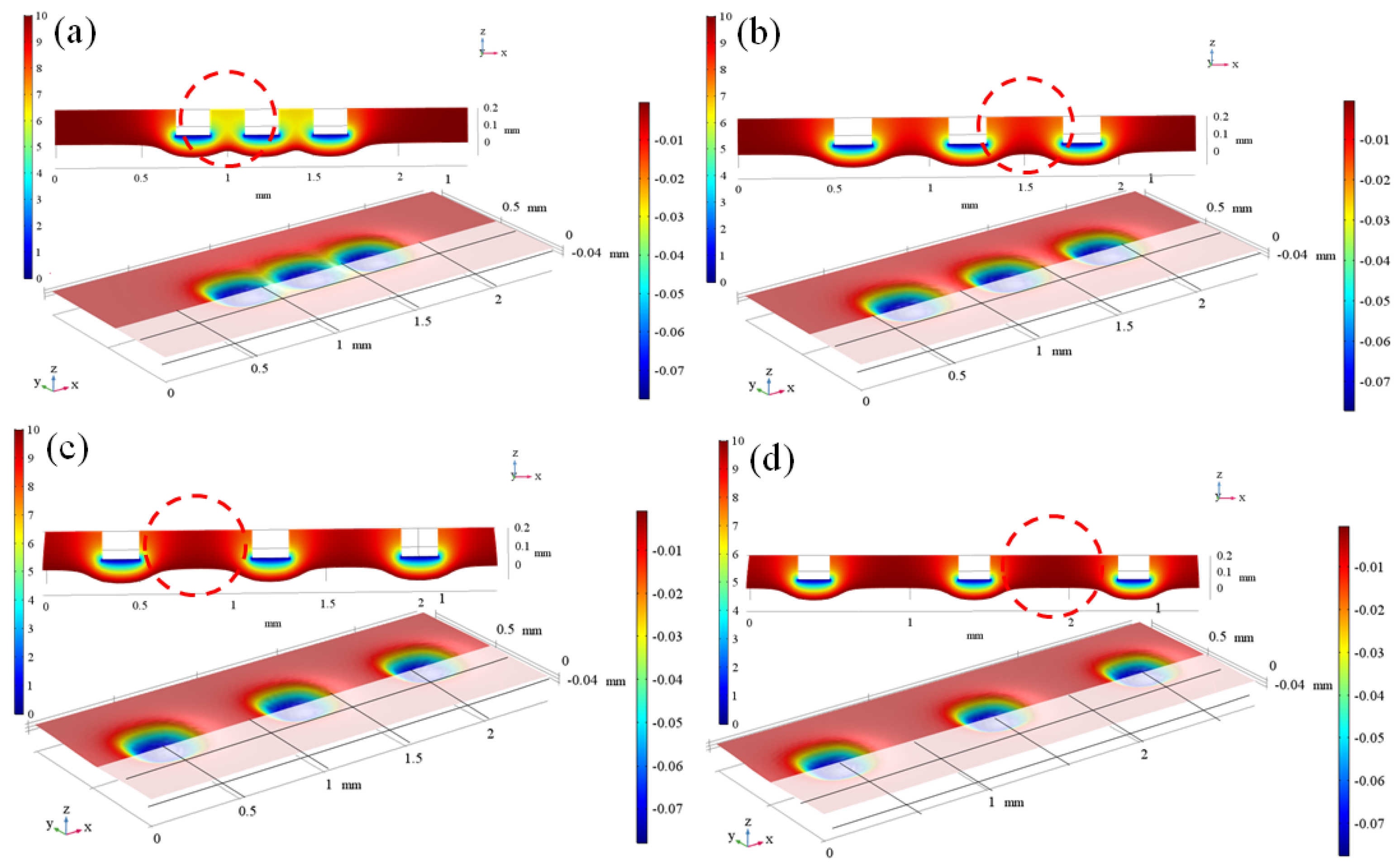
From the analysis presented in Figure 6, it is evident that the electrode size of RUREMM has been specifically designed to measure 200 × 200 μm2. In order to evaluate and compare the electric field, simulations have been conducted with four distinct processing spacing parameters: 400 μm, 600 μm, 800 μm, and 1000 μm. By capturing data from the workpiece surface, the relevant potential curve has been plotted. Thus, the most effective electrode spacing parameter can be determined through this process. The simulation cloud image above illustrates that with specific simulation parameters, the workpiece surface can exhibit square pits of relatively uniform size with good consistency. From the above 3D-simulated cloud image, under certain simulation parameters, the surface of the workpiece can be fitted with square pits of relatively uniform size, and the consistency is good. In the small spacing of 400 μm and 600 μm, the electric field line interferes obviously, forming a disturbing electric field distribution described with dotted circles, which ultimately affects the size and accuracy of the formed micro-pits shown in Figure 6a,b.
As the spacing between electrodes increases, the interaction between electric field regions diminishes gradually. Consequently, when the spacing reaches 800 μm and 1000 μm, the workpiece surface is capable of forming micro-pits with favorable topography, without any noticeable overlapping areas between pits. The simulation of these pits exhibits higher accuracy, and the contours of the micro-pits are more distinct in Figure 6c,d.
Figure 7 illustrates the potential distribution for varying electrode spacing. When the electrode spacing is 400 μm and 600 μm, there is a noticeable overlapping region of potential on the anode workpiece surface described with dotted circles, which indicates that within a specific processing gap, electric fields from adjacent regions can influence and interfere with each other. Consequently, this interference results in uneven micro-pit sizes during final forming and reduced molding accuracy. Conversely, at electrode spacings of 800 μm and 1000 μm, the potential curves do not overlap or interfere with each other, and the molding accuracy remains high without any negative impact. To optimize the ultrasonic transducer’s outer wall design, it is recommended to utilize a micro-array electrode with dimensions of 200 × 200 μm and an electrode spacing of 800 μm, which adheres to the principle of micro-electrode choice in electrochemical micro machining.
5. Experimental Design
5.1. Experimental Equipment
Figure 8 presents a visual depiction of the experimental machining platform. It primarily consists of the machining tool, control system, ultrasonic energy generation system, electrolyte circulation system, pulse power system, and other components. The machining tool control system can precisely realize the displacement control of the XYZ three axes of the machine tool and further ensure the machining interelectrode gap. The electrolyte circulation system has the capability to filter and continuously circulate the electrolyte during the machining process. It also enables efficient control over the speed and flow rate within the loop. The ultrasonic generating system consists of an ultrasonic power supply and a radial ultrasonic transducer, which can adjust the amplitude of the ultrasonic vibration and convert ultrasonic energy into vibration energy for a cathode tool [46,47,48].
Additionally, the radical vibration transducer with micro protrusion and the anode workpiece are fixed on the different revolving stages. The pulse power supply can adjust the pulse frequency and duty cycle pulse parameters during RUREMM. Furthermore, to observe and document the formation of cavitation bubbles between the ultrasonic transducer and the workpiece, a high-speed camera (Keyence, VW6000) is employed. This phenomenon is illustrated in Figure 8b. Table 3 contains the experiment parameters. Additionally, the anode used in the experiment was a SUS304 tube that underwent ultrasonic cleaning. This anode shared the same linear velocity as the ultrasonic transducer.
5.2. Experimental Design
The processing experiments mainly consists of three parts. Firstly, the movement rule of the cavitation bubble was effectively analyzed through photographing the collapsing process of bubbles in a very short period. Then, the influence rules of the different machining parameters on the roughness and aspect ratio of the pits were researched and analyzed, such as ultrasonic amplitude, rotation speed, pulse frequency. In the end, optimized parameters were employed to machine micro array pits with high machining surface quality and precision on the surface of the SS304 cylindrical tube. The choice of the tool electrode is a 304 stainless steel material, which possesses specific stiffness and strength. Additionally, 304 stainless steel exhibits excellent bending strength, electrical conductivity, and high temperature resistance. Therefore, it effectively diminishes the adverse effects of ultrasonic vibration-induced high temperatures shown in Figure 9.
5.3. Analysis of Cavitation
In order to confirm the theoretical change rules of the cavitation bubbles’ continuous expansion, compression and collapse, the cavitation bubbles in the machining gap were captured by a high-speed camera, and circled through a red dotted line, which is shown in Figure 10. Moreover, compared with the simulated results, their motion laws were explored and analyzed through the ultrasonic energy field. In the initial stage, it is clear that no products exist in the machining gap, but the tiny bubble core will be formed when the ultrasonic energy field is continuously applied for 3.5 μs, which is shown in Figure 10a. When the processing time is 10.5 μs, much more dense bubble groups are generated (Figure 10b), and it can be observed that the average radius of the bubble progressively increases. This phenomenon can be attributed to the continuous formation of a negative pressure area in Figure 10c.
However, the radius of the bubble reaches the maximum, which is 61.1 μm and even the ultrasonic transducer is at the max displacement, and the processing time is 24.5 μs (Figure 10d). That is because the cavitation bubble continuously absorbs external energy, and the radius changes to the maximum value when the ultrasonic energy field is at the maximum negative pressure. Finally, the collapse phenomenon of bubbles occurs instantly, and the turbidity phenomenon gradually appears in the machining gap when the processing time is up to 31.5 μs (Figure 10e), which is because the ultrasonic transducer vibrates upward, and the ultrasonic energy field promotes the formation of a high-pressure environment instantaneously.
Additionally, the other large cavitation bubbles and the corrosion impurity gathered in the gap can be extruded out under the action of mechanical and mutual diffusion of the ultrasonic energy field. From Figure 10f, the new cavitation bubble groups continue to reform in the new period due to the unstable machining environment. Moreover, the radius curve of the cavitation bubble with processing time is obtained and compared with the theoretical results in Figure 11. The experimental results show that the cavitation bubble has a similar trend with the theory, which can undergo expansion, compression, collapse and oscillation, and the max deviation is less than 12.5%. The ultrasonic energy field is particularly notable for its ability to create cavitation in the narrow machining gap. This phenomenon has significant benefits, such as enhancing the electric/flow field, facilitating the elimination of joule heat, increasing current density, and ultimately boosting the overall reaction in micro-electrochemical machining.
5.4. Effect of Different Parameters
By analyzing the ultrasonic cavitation bubble, it has been observed that the ultrasonic energy field has the capability to alter the electrolyte’s flow rate and renew the insoluble electrochemical machining byproducts. During RUREMM, the ultrasonic vibration of the tool cathode directly acts on the direction of material erosion, which can weaken the formation of passivation film, enhance the mass transfer between the workpiece and the solution, and finally increase the current density. Moreover, the surface quality and precision of micro-pits in machining can be greatly improved by adjusting the ultrasonic amplitude. Table 4 presents an analysis of the impact of the ultrasonic amplitude on pit size.
In conjunction with Figure 12 depicting the morphology of micro-pits at various amplitudes, it is obvious that at an ultrasonic amplitude of 5 μm, there exists corrosion on the workpiece surface due to the unstable machining process, and the localization is pretty poor. Moreover, the shape of the micro-pits gradually changed from round to square, and the localization was obviously improved with the continuous increase of ultrasonic amplitude from 5 to 15 μm.
However, the three short circuits show that the machining environment was changed to become unstable, the phenomenon of the over corrosion can be clearly seen when the ultrasonic amplitude was increased to 20 μm, and the messy corrosion products and metal frits can be obviously found at the bottom of some micro-pits from the enlarged view of Figure 12d. This is because the equilibrium machining gap is almost zero, which is easier to lead to direct contact between the machining tool and the anode when too large of an ultrasonic amplitude makes the overall processing gap smaller. Moreover, more electrolytic insoluble products will accumulate and constantly adhere to the bottom of the pit or the smooth surface of the workpiece due to the too small processing gap, which is harmful to the whole radial ultrasonic rolling electrochemical micromachining.
Figure 13a,b illustrates the ratio and roughness of the machining pits, respectively, during RUREMM. The roughness of the micro-pits was measured under various conditions using a 3D profiler from Chotest Company, specifically the Super View 1 model. With the increase of ultrasonic amplitude, the depth-to-width ratio of micro-pits improved from 0.0479 to 0.1013, an increase of 111.5%; the roughness of the surface decreased 32.5% from 0.421 μm to 0.284 μm, with the reason being that the ultrasonic energy field has a remarkable capability to enhance both cavitation and flow field distribution, resulting in improved material dissolution rates, and thus the dissolution rate of the workpiece material is increased. However, due to the frequent phenomenon of the short circuits that leads to the whole machining situation becoming unstable, and the aspect ratio decreasing significantly from 0.1013 to 0.0628, which decreased by 38.0%, the roughness increased 49.6% from 0.284 μm to 0.425 μm when the ultrasonic amplitude reached 20 μm. This was because ultrasonic vibration can change the flow field distribution in the machining area within the gap, and can effectively discharge the insoluble products and joule heat generated during the machining process. Meanwhile, the high-pressure gap generated by the ultrasonic vibration can effectively discharge the gas generated during the machining process, reduce the volume fraction of the gas in the flow field in the machining area, and help improve the machining precision and surface quality of the micro-texture. The experimental results indicated that the ideal ultrasonic amplitude falls within the range of 15 to 20 μm, with particular significance.
During EMM and RUREMM, the dissolution rate can be obviously changed by the rotation speed and can effectively influence the whole removal rate of electrochemical micro machining. Table 5 shows the analysis result regarding the influence of rotation speed on pit size. In addition, Figure 14 depicts the morphology of array micro-pits at various rotation speeds. It reveals an interesting observation that there is an occurrence of overlap between the corrosion area and the machining size when the rotation speed is 0.004 r/min. Moreover, the surface of the micro-pits is not clear, and tends to be elliptical with poor localization from the local enlarged view. This is because the voltage is unchanged, the roll erosion rate increases, the material removal is unstable, and the concentrated corrosion removal ability is weak, resulting in a decrease in the overall current density between the tool electrode and the opposite machining area. The depth of the array micro-pits is not significantly reduced. However, when the roll erosion rate increases, the electric field radiation range on the workpiece surface per unit time changes greatly, and the width of the array micro-pits changes significantly.
However, with the increase of the rotation speed from 0.004 r/min to 0.008 r/min, the width of the micro-pits gradually decreases, and the stray corrosion phenomenon gradually weakens. As the rotation speed is up to 0.01 r/min, the topography of the micro-pits becomes significantly indistinct. Only localized pitting corrosion is observed on the surface of the workpiece. This is because a large rotation speed will result in less processing time in the unit area, the electrode will be turned out of the processing area, resulting in the uncompleted machining, and the quality of the workpiece will be affected.
The relationship between the rotation speed and the machining size, including the depth-to-width ratio and roughness during EMM and RUREMM, is illustrated in Figure 15a,b. With the increase of rotation speed, the aspect ratio of micro-pits improved from 0.0533 to 0.0594, an increase of 11.4%, and the roughness of the surface decreased 18.5% from 0.523 μm to 0.426 μm by EMM. Besides, the aspect ratio of micro-pits increased 14.7% and the roughness of the surface decreased 19.8% by RUREMM; the reason for this is the instability of material removal and the limited ability to concentrate corrosion, which leads to the decrease in the overall current density between the machining tool and the opposite area as the rotation speed increases. However, the depth is not significantly reduced, and the electric field radiation range on the workpiece surface is significantly changed in unit time, and the width of the array micro-pits is reduced significantly.
Due to the concentrated corrosion ability of the material per unit time is weakened, even if there is the effect of ultrasonic energy field in the narrow machining gap when the rotation speed is up to 0.01 r/min. The aspect ratio of the micro-pits is reduced by 55.9% and 42.4%, and the roughness of the surface is improved by 27.7% and 38.7% by EMM and RUREMM. Moreover, the insoluble products cannot be timely and uniformly removed, resulting in a reduction in the overall current density, the workpiece surface is not completely corroded, and the whole surface quality will be ultimately influenced. In conclusion, the range of 0.006 r/min to 0.008 r/min was suggested as the optical experimental parameters.
The pulse power supply is used to change the current density in the pulse type, and change the pressure of the electrolyte, and the polarization effect is reduced between the electrodes, which can significantly enhance the workpiece’s surface quality. Table 6 illustrates the analysis of the effect of pulse frequency on pit size, while Figure 16 illustrates the different appearances of the array micro-pits under various pulse frequencies in both EMM and RUREMM processes. From Figure 16d,h, the phenomenon of short circuit still occurs, and the outline of the micro-pits has become blurred, and the processed surface has been damaged by corrosion. In addition, it is obvious that the profile of the micro-pits is clearer, and the stray corrosion is weakened compared with EMM. Due to the cavitation phenomenon promoted by the ultrasonic energy field, the non-viscous electrolytic products will be removed constantly, and finally improve the whole accuracy of machining.
Figure 17a shows the aspect ratio of array pits in different pulse frequencies, when the pulse frequency increased from 8 kHz to 16 kHz, the average depth-to-width ratio tends to be flat and almost constant, about 0.0594 during EMM, while improving to 2.9% through RUREMM. This is because the increase of the reverse current is conducive to eliminating the concentration polarization; the polarization potential distribution on the surface of the workpiece is uniform, so that the material removal is more uniform, and the replication accuracy of the micro-pits will be higher. Figure 17b shows the roughness of the EMM and RUREMM, which have similar variation during the different pulse frequencies. Besides, the roughness of the surface reduces by 17.5% and 18.6% when the pulse frequency increases during EMM and RUREMM. However, the aspect ratio of micro-pits reduces by 1.0% and 21.7%, and the roughness of the surface improves by 17.5% and 28.1% when the pulse frequency is up to 20 kHz during EMM and RUREMM. That is because the whole current density is clearly affected by the charging time of the double electric layer, which results in pulse frequency increasing, and pulse period becoming shorter, which can limit the electrochemical reaction area under the same pulse voltage according to the charge and discharge principle of the double electric layer. Combined with the above analysis, it can be concluded that the optimal applied pulse frequency is 16 kHz, which has the higher aspect ratio and surface accuracy.
5.5. Fabrication of Array Micro-Dimples
In conclusion, the optical parameters for good performance and high precision are chosen so that the ultrasonic amplitude is 15 μm, the rotation speed is 0.008 r/min, and the pulse frequency is 16 kHz, and the diagram of array micro-pits with optimized parameters is shown in Figure 18a,b. Besides, the cross-sectional profile curve of micro-pits was analyzed during RUREMM shown in Figure 18c. It can be figured out that the average width is 212.4 μm, the depth is 21.8 μm, the aspect ratio is 0.1026 μm, and the roughness of the smooth surface is 0.253 μm with consistent size, no stray corrosion phenomenon, high localization and good surface quality.
6. Conclusions
In this paper, the cavitation phenomenon of the bubble between the ultrasonic transducer and the cylindrical SUS304 tube was analyzed, and the electric field’s impact on the machining gap was studied through the COMSOL5.2 simulation software. Furthermore, the localization, surface quality and machining accuracy of the workpiece surface were examined and compared between RUREMM and EMM. Based on the analysis conducted, the relevant conclusions are as follows:
- (1)
- During RUREMM, the theory of cavitation was analyzed i.e., the bubble undergoes expansion, compression, collapse and oscillation when the ultrasonic transducer vibrates upwards or downwards in the narrow machining gap. In addition, the experimental results show that the similar trend with the theory and the max deviation is less than 12.5%.
- (2)
- Through the utilization of the COMSOL simulation software, modifications were implemented to fine-tune the dimensions of the micro-roll etching electrode. Consequently, the optimal measurements for the electrode were ascertained to be 200 × 200 μm2 in size, with an electrode spacing of 800 μm.
- (3)
- Compared with the EMM, the localization and the surface accuracy can be improved obviously through RUREMM. Furthermore, it was noted that the occurrence of stray corrosion in micro-pits noticeably reduced as ultrasonic amplitude, rotation speed, and pulse frequency increased. However, the higher value of the parameters will deteriorate the whole surface accuracy and quality.
- (4)
- In conclusion, the ultrasonic amplitude of 15 μm, the rotation speed of 0.008 r/min, and the pulse frequency of 16 kHz were chosen to be the optical parameters for good performance and high precision. In addition, the ultrasonic energy field resulted in the formation of array micro-pits. These pits have an average width of 212.4 μm, a depth of 21.8 μm, an aspect ratio of 0.1026 μm, and a roughness of 0.253 μm on the smooth surface. This demonstrates the effectiveness of RUREMM.
Author Contributions
Conceptualization, W.T. and L.L.; tables and figures generation, W.T. and L.L.; article identification, screening, retrieval, selection, and analysis, W.T. and L.L.; review and editing, W.T.; formal analysis and investigation, L.L.; writing—original draft preparation, W.T. and L.L.; supervision, L.L. All authors have read and agreed to the published version of the manuscript.
Funding
This work was supported in part by the Talent Introduction Project Foundation of Ningbo Polytechnic under Grant No. NZ23RC01; The National Natural Science Foundation of China under Grant No. 51975532 and 51475428; The Zhejiang Provincial Natural Science Foundation under Grant No. LY19E050007 and LQ23E050017.
Data Availability Statement
Data are contained within the article.
Conflicts of Interest
The authors declare no conflict of interest.
References
- Jia, S.L.; Han, J.; Liu, Y.D.; Shi, W.T.; Yang, Y.L.; Ma, T. Comparative study on cutting performance of different micro-texturing milling tools for preparing the L-PBF-formed TC4 workpieces. J. Manuf. Process. 2023, 108, 596–6096. [Google Scholar] [CrossRef]
- Quang, T.B.; Seung, K.P.; Jong, K. A static model for micro-pattern forming prediction in rolling-based surface texturing. Int. J. Adv. Manuf. Technol. 2017, 58, 92. [Google Scholar]
- Zheng, G.A.; Xu, P.; Li, L.; Fan, X.H. Investigations of the Formation Mechanism and Pressure Pulsation Characteristics of Pipeline Gas-Liquid Slug Flows. J. Mar. Sci. Eng. 2024, 12, 590. [Google Scholar] [CrossRef]
- Ning, P.; Zhao, J.; Ji, S.; Li, J.; Dai, H. Surface defects formation mechanism of Mg2Si/Al composites by micro cutting. Precis. Eng. 2024, 88, 324–340. [Google Scholar] [CrossRef]
- Ilie, F.; Cotici, C.D.; Hristache, A.-F. Study of the Grinding Process by Friction of Cereal Grains in Stone Mills. Processes 2023, 11, 3376. [Google Scholar] [CrossRef]
- Gao, S.; Duan, X.; Zhu, K.; Zhang, Y. Investigation of the tool flank wear influence on cutter-workpiece engagement and cutting force in micro milling processes. Mech. Syst. Signal Process. 2024, 209, 111104. [Google Scholar] [CrossRef]
- Bibeka, N.P.; Sounak, K.C.; Janakarajan, R. Fabrication of micro-textured surfaces using Gravity-assisted EDM process with foil electrode to induce hydrophobicity on Cu surface. Mater. Today Proc. 2023, 77, 597–602. [Google Scholar]
- Md, S.S.; Probir, S. Assessment of vibration-assisted micro-EDM dressing process-stability by monitoring and analyzing debris evacuation during Ti-6Al-7Nb machining. J. Manuf. Process. 2021, 66, 250–268. [Google Scholar]
- Julfekar, A.; Pradeep, D. Gas bubbles entrapment mechanism in the electrochemical discharge machining involving multi-tip array electrodes. J. Manuf. Process. 2023, 99, 38–52. [Google Scholar]
- Liu, Y.; Fang, X.L.; Qu, N.S.; Zhang, Z.Y.; Lu, J.Z. Simultaneous gas electrical discharge and electrochemical jet micromachining of titanium alloy in high-conductivity salt solution. J. Mater. Process. Tech. 2023, 317, 118000. [Google Scholar] [CrossRef]
- Miki, K.; Ryo, I.; Kanari, N.; Hiroto, S.; Akio, Y. Micro-dimple textured surface produced by laser-induced particle impact test and improving tribological performance. Mater. Today Commun. 2024, 38, 108213. [Google Scholar]
- Lei, P.; Zhang, P.; Song, S.; Liu, Z.; Yan, H.; Sun, T.; Lu, Q.; Chen, Y.; Gromov, V.; Shi, H. Research status of laser surface texturing on tribological and wetting properties of materials A review. Optik 2024, 298, 171581. [Google Scholar] [CrossRef]
- Liang, S.X.; Su, J.H.; Zhang, H.; Liu, H.R.; Tan, C.W.; Chen, B.; Song, X.G. The effect of groove texturing direction on laser joining of titanium alloy to CFRTP. Opt. Laser Technol. 2024, 171, 110416. [Google Scholar] [CrossRef]
- Orazi, L.; Pelaccia, R.; Siciliania, V.; Oubellaouch, K.; Mazzonetto, M.; Reggiani, B. Ultrafast laser texturing to improve wettability of polyimide (Kapton) films. J. Manuf. Process. 2023, 107, 368–375. [Google Scholar] [CrossRef]
- Du, C.Y.; Dai, Y.F.; Hu, H.; Guan, C.L.; Liu, J.F.; Lai, T.; Tian, Y.Y. Atomic-level insight into process and mechanism of ion beam machining on aluminum optical surface. Vacuum 2024, 222, 113011. [Google Scholar] [CrossRef]
- Xie, L.B.; Tian, Y.; Shi, F.; Guo, S.P.; Zhou, G. Adaptive Processing Strategy of Pulse Ion Beam for Sub-nanometer Precision Optical Components. J. Mater. Process. Tech. 2024, 17, 118341. [Google Scholar] [CrossRef]
- Takenori, O.N.O. Sharpening of the diamond tool edge by the Ar ion beam machine tool. Procedia Manuf. 2021, 53, 246–250. [Google Scholar]
- Zhou, H.; Yue, X.M.; Luo, H.X.; Liu, B.H.; Zhang, S.Y. Electrochemical micromachining of micro hole using micro drill with non-conductive mask on the machined surface. J. Manuf. Process. 2020, 59, 366–377. [Google Scholar] [CrossRef]
- Deng, H.R.; Tao, J.; Ren, W.F.; Sun, H.H.; Zou, Z.Q.; Xu, J.K. Experimental study on electrochemical machining of TC11 titanium alloy blades based on cylindrical array microstructure cathodes. Colloids Surf. A Physicochem. Eng. Asp. 2023, 670, 131620. [Google Scholar] [CrossRef]
- Winkelmann, C.; Lang, W. Influence of the electrode distance and metal ion concentration on the resulting structure in electrochemical micromachining with structured counter electrodes. Int. J. Mach. Tools Manuf. 2013, 72, 25–31. [Google Scholar] [CrossRef]
- Zhang, S.; Zhou, J.; Fu, F.; Hu, G.; Zhao, Y.; Wang, L.; Xu, Y. Electric arc electrochemical machining of Ti6Al4V titanium alloy based on high-pressure internal flushing fluid. J. Manuf. Process. 2024, 112, 60–81. [Google Scholar] [CrossRef]
- Ge, M.; Zheng, G.A. Fluid-solid mixing transfer mechanism and flow patterns of the double-layered impeller stirring tank by the CFD-DEM method. Energies 2024, 17, 1513. [Google Scholar] [CrossRef]
- Liu, Z.M.; Lian, Z.X.; Yang, J.D.; Xu, J.K.; Tian, Y.L.; Yu, H.D. High-efficient and scalable fabrication of robust superhydrophobic microarrays through maskless electrochemical machining. Colloids Surf. A Physicochem. Eng. Asp. 2024, 681, 132700. [Google Scholar] [CrossRef]
- Wang, M.H.; Chen, X.; Tong, W.J.; Wang, J.J.; Wang, X.D. Influences of gap pressure on machining performance in radial ultrasonic rolling electrochemical micromachining. Int. J. Adv. Manuf. Technol. 2020, 107, 157–166. [Google Scholar] [CrossRef]
- Chen, X.L.; Gu, X.L.; Saxena, K.K.; Arshad, M.H.; Huang, J.Z.; Reynaerts, D. Enhancing shape precision in jet electrochemical additive micro-manufacturing process through confined electrolyte. Precis. Eng. 2023, 84, 69–80. [Google Scholar] [CrossRef]
- Liu, W.D.; Li, W.T.; Zhao, Y.H.; Wang, Z.P.; Guo, Z.Y. Gap effect in electrochemical jet machining. J. Manuf. Process. 2023, 99, 652–662. [Google Scholar] [CrossRef]
- Li, H.S.; Wang, G.Q.; Li, L.W.; Gao, C.P.; Qu, N.S.; Zhu, D. Through-mask electrochemical machining of hole arrays on molybdenum sheets. Int. J. Adv. Manuf. Technol. 2017, 93, 2393–2401. [Google Scholar] [CrossRef]
- Chen, X.L.; Qu, N.S.; Li, H.S.; Guo, Z.N. Removal of islands from micro-dimple arrays prepared by through-mask electrochemical micromachining. Precis. Eng. 2015, 39, 204–211. [Google Scholar] [CrossRef]
- Yu, M.X.; Du, L.Q.; Zhai, K.; Cheng, H.H.; Wang, F.L.; Li, A.Q.; Wang, Z.M. Towards understanding uniformity of megasonic-assisted through-mask electrochemical micromachining based on bubble dynamics. J. Manuf. Process. 2023, 96, 125–137. [Google Scholar] [CrossRef]
- Sun, Y.K.; Ling, S.Y.; Zhao, D.Y.; Liu, J.Y.; Liu, Z.A.; Song, J.L. Through-mask electrochemical micromachining of micro pillar arrays on aluminum. Surf. Coat. Technol. 2020, 404, 126277. [Google Scholar] [CrossRef]
- Wang, M.H.; Tong, W.J.; Qiu, G.Z.; Xu, X.F.; Speidel, A.; Mitchell-Smith, J. Multiphysics study in air-shielding electrochemical micromachining. J. Manuf. Process. 2019, 43, 124–135. [Google Scholar] [CrossRef]
- Wang, M.H.; Bao, Z.Y.; Qiu, G.Z.; Xu, X.F. Fabrication of micro-dimple arrays by AS-EMM and EMM. Int. J. Adv. Manuf. Technol. 2017, 93, 787–797. [Google Scholar] [CrossRef]
- Li, L.; Li, Q.H.; Ni, Y.S.; Wang, C.Y.; Tan, Y.F.; Tan, D.P. Critical penetrating vibration evolution behaviors of the gas-liquid coupled vortex flow. Energy 2024, 292, 130236. [Google Scholar] [CrossRef]
- Wu, J.; Li, L.; Yin, Z.; Li, Z.; Wang, T.; Tan, Y.; Tan, D. Mass transfer mechanism of multiphase shear flows and interphase optimization solving method. Energy, 2024; in press. [Google Scholar] [CrossRef]
- Li, L.; Xu, W.X.; Tan, Y.F.; Yang, Y.S.; Yang, J.G.; Tan, D.P. Fluid-induced vibration evolution mechanism of multiphase free sink vortex and the multi-source vibration sensing method. Mech. Syst. Signal Process 2023, 189, 110058. [Google Scholar] [CrossRef]
- Li, Q.; Xu, P.; Li, L.; Xu, W.; Tan, D. Investigation on the lubrication heat transfer mechanism of the multilevel gearbox by the lattice Boltzmann method. Processes 2024, 12, 381. [Google Scholar] [CrossRef]
- Wang, M.H.; Zhang, R.Y.; Shang, Y.C.; Zheng, J.S.; Wang, X.D.; Xu, X.F. Micro-milling microstructures in air-shielding ultrasonic assisted electrochemical machining. J. Manuf. Process. 2023, 97, 171–184. [Google Scholar] [CrossRef]
- Liu, F.Y.; Chen, T.; Duan, Z.Y.; Suo, Y.H.; Zhang, C.D. Ultrasonic assisted pecking drilling process for CFRP Ti laminated materials. J. Manuf. Process. 2023, 108, 834–851. [Google Scholar] [CrossRef]
- Chen, Z.H.; Liu, Y.; Wang, T.B.; Wang, K. Ultrasonic assisted electrochemical discharge milling of complex glass microstructure with high-quality. J. Manuf. Process. 2023, 94, 94–106. [Google Scholar] [CrossRef]
- Wang, T.B.; Liu, Y.; Lv, Z.; Wang, K. Theoretical and experimental study on localization improvement in ultrasonic vibration–assisted spark-assisted electrochemical drilling process. Int. J. Adv. Manuf. Technol. 2022, 121, 5311–5328. [Google Scholar] [CrossRef]
- Wu, H.Q.; Duan, W.H.; Sun, L.H.; Zeng, J.; Li, S.S.; Wang, Q.; Wu, Y.B.; Chen, Y.H. Effect of ultrasonic vibration on the machining performance and mechanism of hybrid ultrasonic vibration plasma oxidation assisted grinding. J. Manuf. Process. 2023, 94, 466–478. [Google Scholar] [CrossRef]
- Shu, T.; Liu, Y.; Wang, K.; Peng, T.F.; Guan, W.C. Ultrasonic vibration-aided electrochemical drill-grinding of SLM-printed Hastelloy X based on analysis of its electrochemical behavior. Electrochem. Commun. 2022, 135, 107208. [Google Scholar] [CrossRef]
- Fujisawa, T.; Inaba, K.; Yamamoto, M.; Kato, D. Multiphysics Simulation of Electrochemical Machining Process for Three-Dimensional Compressor Blade. J. Fluid. Eng. 2008, 130, 8. [Google Scholar] [CrossRef]
- Borden, M.A.; Kruse, D.E.; Caskey, C.F.; Zhao, S.; Dayton, P.A.; Ferrara, K.W. Influence of lipid shell physicochemical properties on ultrasound-induced microbubble destruction. IEEE Trans. Ultrason. Ferroelectr. Freq. Control 2005, 52, 1992–2002. [Google Scholar] [CrossRef] [PubMed]
- Yan, Q.; Li, D.H.; Wang, K.F.; Zheng, G.A. Study on the Hydrodynamic Evolution Mechanism and Drift Flow Patterns of Pipeline Gas-Liquid Flow. Processes 2024, 12, 695. [Google Scholar] [CrossRef]
- Li, L.; Xu, P.; Xu, W.X.; Lu, B.; Wang, C.Y.; Tan, D.P. Multi-field coupling vibration patterns of the multiphase sink vortex and distortion recognition method. Mech. Syst. Signal Process. 2024; in press. [Google Scholar]
- Li, L.; Lu, B.; Xu, W.X.; Wang, C.Y.; Wu, J.F.; Tan, D.P. Dynamic behaviors of multiphase vortex-induced vibration for hydropower energy conversion. Energy 2024, in press.
- Yan, Q.; Fan, X.; Li, L.; Zheng, G. Investigations of the mass transfer and flow field disturbance regulation of the gas–liquid–solid flow of hydropower stations. J. Mar. Sci. Eng. 2023, 12, 84. [Google Scholar] [CrossRef]
Figure 1.
The schematic view of RUREMM.

Figure 2.
Schematic model of material anodic dissolution. (a) Upstairs, (b) downstairs.

Figure 3.
Radius variation diagram of cavitation bubble.

Figure 4.
Simulation model. (a) Physical model, (b) meshed model.

Figure 5.
Influence diagram of electric field on different electrode size. (a) 50 × 50, (b) 100 × 100, (c) 200 × 200, and (d) 300 × 300.
Figure 5.
Influence diagram of electric field on different electrode size. (a) 50 × 50, (b) 100 × 100, (c) 200 × 200, and (d) 300 × 300.

Figure 6.
Influence diagram of electric field on different electrode spacing. (a) 400, (b) 600, (c) 800, and (d) 1000.
Figure 6.
Influence diagram of electric field on different electrode spacing. (a) 400, (b) 600, (c) 800, and (d) 1000.

Figure 7.
Diagram of potential distribution on different electrode spacing. (a) 400, (b) 600, (c) 800, and (d) 1000.
Figure 7.
Diagram of potential distribution on different electrode spacing. (a) 400, (b) 600, (c) 800, and (d) 1000.

Figure 8.
Experimental equipment of RUREMM. (a) Whole view, (b) enlarged view.

Figure 9.
Physical diagram of array microelectrode on cylindrical surface. (a) Global view, (b) enlarged view.
Figure 9.
Physical diagram of array microelectrode on cylindrical surface. (a) Global view, (b) enlarged view.

Figure 10.
Cavitation bubbles. (a) 3.5 μs, (b) 10.5 μs, (c) 17.5 μs, (d) 24.5 μs, (e) 31.5 μs, and (f) 35 μs.
Figure 10.
Cavitation bubbles. (a) 3.5 μs, (b) 10.5 μs, (c) 17.5 μs, (d) 24.5 μs, (e) 31.5 μs, and (f) 35 μs.

Figure 11.
The radius view of cavitation bubbles.

Figure 12.
Morphology of array micro-pits by RUREMM. (a) 5 μm, (b) 10 μm, (c) 15 μm, and (d) 20 μm.

Figure 13.
Effects of ultrasonic amplitude during RUREMM. (a) Aspect ratio, (b) roughness.

Figure 14.
Morphology of array of the micro-pits under different rotation speeds (r/min), EMM: (a) 0.004, (b) 0.006, (c) 0.008, (d) 0.01, RUREMM: (e) 0.004, (f) 0.006, (g) 0.008, and (h) 0.01.
Figure 14.
Morphology of array of the micro-pits under different rotation speeds (r/min), EMM: (a) 0.004, (b) 0.006, (c) 0.008, (d) 0.01, RUREMM: (e) 0.004, (f) 0.006, (g) 0.008, and (h) 0.01.

Figure 15.
Effects of rotation speed on array pit dimensions during EMM and RUREMM. (a) Aspect ratio, (b) roughness.
Figure 15.
Effects of rotation speed on array pit dimensions during EMM and RUREMM. (a) Aspect ratio, (b) roughness.

Figure 16.
Morphology of the array of micro-pits under different pulse frequencies (kHz), EMM: (a) 8, (b) 12, (c) 16, (d) 20, RUREMM: (e) 8, (f) 12, (g) 16, and (h) 20.
Figure 16.
Morphology of the array of micro-pits under different pulse frequencies (kHz), EMM: (a) 8, (b) 12, (c) 16, (d) 20, RUREMM: (e) 8, (f) 12, (g) 16, and (h) 20.

Figure 17.
Effects of pulse frequency on array pit dimensions during EMM and RUREMM. (a) Aspect ratio, (b) roughness.
Figure 17.
Effects of pulse frequency on array pit dimensions during EMM and RUREMM. (a) Aspect ratio, (b) roughness.

Figure 18.
The diagram of experimental results with optimized parameters. (a) Whole view, (b) enlarged view, and (c) cross-sectional dimension.
Figure 18.
The diagram of experimental results with optimized parameters. (a) Whole view, (b) enlarged view, and (c) cross-sectional dimension.


Table 1.
Matlab R2023b analysis parameters.
| Parameter | Symbol | Value | Unit |
|---|---|---|---|
| Liquid density | ρ | 937 | kg/m3 |
| Liquid viscosity | μ | 0.001 | Pa.s |
| Adiabatic index | κ | 4/3 | |
| Liquid surface tension | σ | 0.0725 | N/m |
| Atmospheric pressure | P0 | 101,320 | Pa |
| Vapor pressure of bubble | PV | 2330 | Pa |
| Frequency | f | 28 | kHz |
Table 2.
COMSOL5.2 analysis parameters.
| Parameter | Unit | Value |
|---|---|---|
| Cathode potential | V | 0 |
| Anode potential | V | 10 |
| Machining gap | μm | 50 |
| Electrode size | μm | 50 × 50, 100 × 100, 200 × 200, 300 × 300 |
| Electrode spacing | μm | 400, 600, 800, 1000 |
Table 3.
Experimental conditions.
| Item | Symbol | Value | Unit |
|---|---|---|---|
| Protrusion size | A × A | 200 × 200 | μm |
| Rotation speed | Vr | 0.004, 0.006, 0.008, 0.01 | r/min |
| Inter-electrode gap | Δ | 50 | μm |
| Pulse voltage | U | 10 | V |
| Pulse frequency | f1 | 8, 12, 16, 20 | kHz |
| Workpiece diameter | D | 50 | mm |
| Electrolytic velocity | Ve | 3 | m/s |
| Electrolyte concentration | wt | 10 | % |
| Electrolyte temperature | Te | 25 | °C |
| Ultrasonic amplitude | A | 5, 10, 15, 20 | μm |
| Ultrasonic vibration frequency | f2 | 28 | kHz |
| Machining time | t | 10 | min |
Table 4.
Analysis table regarding the influence of ultrasonic amplitude on pit size.
| Items | Amplitude (μm) | Short Circuits | Width (μm) | Depth (μm) | Aspect Ratio |
|---|---|---|---|---|---|
| RUREMM | 5 | 0 | 315.2 | 15.1 | 0.0479 |
| 10 | 0 | 265.1 | 18.9 | 0.0713 | |
| 15 | 0 | 221.1 | 22.4 | 0.1013 | |
| 20 | 3 | 210.1 | 13.2 | 0.0628 |
Table 5.
Analysis table regarding the influence of rotation speed on pit size.
| Items | Rotation Speed (r/min) | Short Circuits | Width (μm) | Depth (μm) | Aspect Ratio |
|---|---|---|---|---|---|
| EMM | 0.004 | 4 | 352.6 | 18.8 | 0.0533 |
| 0.006 | 0 | 306.2 | 16.6 | 0.0542 | |
| 0.008 | 0 | 257.7 | 15.3 | 0.0594 | |
| 0.010 | 1 | 194.6 | 5.1 | 0.0262 | |
| RUREMM | 0.004 | 1 | 320.5 | 28.3 | 0.0883 |
| 0.006 | 0 | 270.6 | 25.1 | 0.0928 | |
| 0.008 | 0 | 221.1 | 22.4 | 0.1013 | |
| 0.010 | 3 | 180.1 | 10.5 | 0.0583 |
Table 6.
Analysis table regarding the influence of pulse frequency on pit size.
| Items | Pulse Frequency (kHz) | Short Circuits | Width (μm) | Depth (μm) | Aspect Ratio |
|---|---|---|---|---|---|
| EMM | 8 | 0 | 271.7 | 16.1 | 0.0594 |
| 12 | 0 | 257.7 | 15.3 | 0.0594 | |
| 16 | 0 | 244.5 | 14.6 | 0.0597 | |
| 20 | 2 | 216.5 | 12.8 | 0.0591 | |
| RUREMM | 8 | 0 | 233.6 | 23.3 | 0.0997 |
| 12 | 0 | 221.1 | 22.4 | 0.1013 | |
| 16 | 0 | 212.4 | 21.8 | 0.1026 | |
| 20 | 0 | 195.4 | 15.7 | 0.0803 |
Disclaimer/Publisher’s Note: The statements, opinions and data contained in all publications are solely those of the individual author(s) and contributor(s) and not of MDPI and/or the editor(s). MDPI and/or the editor(s) disclaim responsibility for any injury to people or property resulting from any ideas, methods, instructions or products referred to in the content. |
© 2024 by the authors. Licensee MDPI, Basel, Switzerland. This article is an open access article distributed under the terms and conditions of the Creative Commons Attribution (CC BY) license (https://creativecommons.org/licenses/by/4.0/).
Share and Cite
MDPI and ACS Style
Tong, W.; Li, L. Experimental Research of Ultrasonic Cavitation Evolution Mechanism and Model Optimization of RUREMM on Cylindrical Surface. Processes 2024, 12, 884. https://doi.org/10.3390/pr12050884
AMA Style
Tong W, Li L. Experimental Research of Ultrasonic Cavitation Evolution Mechanism and Model Optimization of RUREMM on Cylindrical Surface. Processes. 2024; 12(5):884. https://doi.org/10.3390/pr12050884
Chicago/Turabian StyleTong, Wenjun, and Lin Li. 2024. "Experimental Research of Ultrasonic Cavitation Evolution Mechanism and Model Optimization of RUREMM on Cylindrical Surface" Processes 12, no. 5: 884. https://doi.org/10.3390/pr12050884
Note that from the first issue of 2016, this journal uses article numbers instead of page numbers. See further details here.