
Improving Speed Characteristics of High-Torque-Density Motors for Physical Human–Robot Interaction Using an Independent Three-Phase Winding Structure


Department of Mechanical Engineering, Incheon National University, 119, Academy-ro, Yeonsu-gu, Incheon 22012, Republic of Korea
*
Author to whom correspondence should be addressed.
Actuators 2024, 13(5), 161; https://doi.org/10.3390/act13050161
Submission received: 28 March 2024
/
Revised: 23 April 2024
/
Accepted: 25 April 2024
/
Published: 27 April 2024
(This article belongs to the Section High Torque/Power Density Actuators)
Abstract
:Recently, due to the decrease in labor force, increase in labor costs, and the desire for improved quality of life, research on robots has been actively conducted to address these issues. However, it is currently difficult to find robots that physically interact with humans. The reason is that the actuators of robots do not have a high torque density on their own. To solve this problem, high-torque-density motors, such as proprioceptive actuators, are being researched. However, the torque density is still insufficient for physical interaction with humans, so a motor with higher torque density has been developed. However, high-torque-density motors have the disadvantage of lower speed characteristics due to increased Back EMF levels. Therefore, to address the deterioration of speed characteristics in the developed motor, we applied the independent three-phase winding structure to improve the speed characteristics. Consequently, through comparison with the Y-Connection and D-Connection, we propose the most suitable winding structure for high-torque-density motors intended for physical interaction with humans.
1. Introduction
As the workforce declines, labor costs rise, and the desire for improved living standards grows, the study of robotics across various domains has experienced a notable increase in addressing these societal challenges and demands. However, in modern environments where humans are closely involved with pHRI (physical human–robot interaction), the prevalent robots are mostly guided robots and robotic vacuum cleaners. It is challenging to find robots that physically interact with humans. The main issue stems from the insufficient torque density produced by the robot’s propulsion systems, resulting in the inevitable need for reducers in the joints of robots. As a result, this decrease in joint back-drivability poses a significant risk to humans of unexpected collisions [1]. This is the primary reason why we seldom see robots that can interact with humans in a physically safe way.
The main methods currently used for robotic actuators are hydraulic, pneumatic, and motor-based systems, each with its own advantages and disadvantages. Hydraulic systems have the advantage of excellent torque generation capabilities, but they suffer from hydraulic fluid leakage, and require additional equipment such as pumps leading to increased maintenance, noise, and significant weight [2]. Pneumatic systems are clean and easy to maintain, but like hydraulic systems, they require additional equipment and are sensitive to small changes in pressure or flow rate, making them difficult to control [3]. As a result, hydraulic and pneumatic actuators present many challenges when used in robots that operate in close proximity to humans. On the other hand, electric motors offer relatively low cost, cleanliness, small noise, and volume, making them suitable for robotic joints that physically interact with humans in their vicinity. However, the torque density of conventional BLDC motors is insufficient for robots to achieve specific objectives, necessitating the inevitable use of reducers with high gear ratios. Additionally, the nonlinear friction generated in the gears makes it difficult to estimate torque from the motor current, making the use of torque sensors essential.
Therefore, to address these issues, an actuator called a proprioceptive actuator was developed [4,5,6,7,8,9]. Proprioceptive actuators do not require a torque sensor and use a high-torque-density motor with a low gear ratio transmission and a current sensor in the current controller as a proprioceptive sensor. However, the torque density is still low, and the pulsating torque, which can be amplified by the gear reducer, is high. Inspired by the concept of proprioceptive actuators, a high-torque-density motor was developed to be implemented in legged or wearable robots for physical interactions.
However, high-torque-density motors also have a high Back EMF, which results in lower speed characteristics. Therefore, this paper aims to solve the problem of reduced speed characteristics in high-torque-density motors by applying the independent three-phase winding structure method. Unlike conventional Y-Connection and D-Connection winding structures, the independent three-phase BLDC motor allows the full voltage to be applied to a single phase without voltage division from the voltage source [10]. This enables the use of a higher phase voltage, which can improve low-speed characteristics. Accordingly, this paper verifies the effectiveness of the independent three-phase BLDC motor through comparative experiments of speed characteristics. The experiments compare the conventional Y-Connection winding structure, D-Connection winding structure, and the proposed independent three-phase winding structure.
2. Three-Phase BLDC Motor and Controller Design
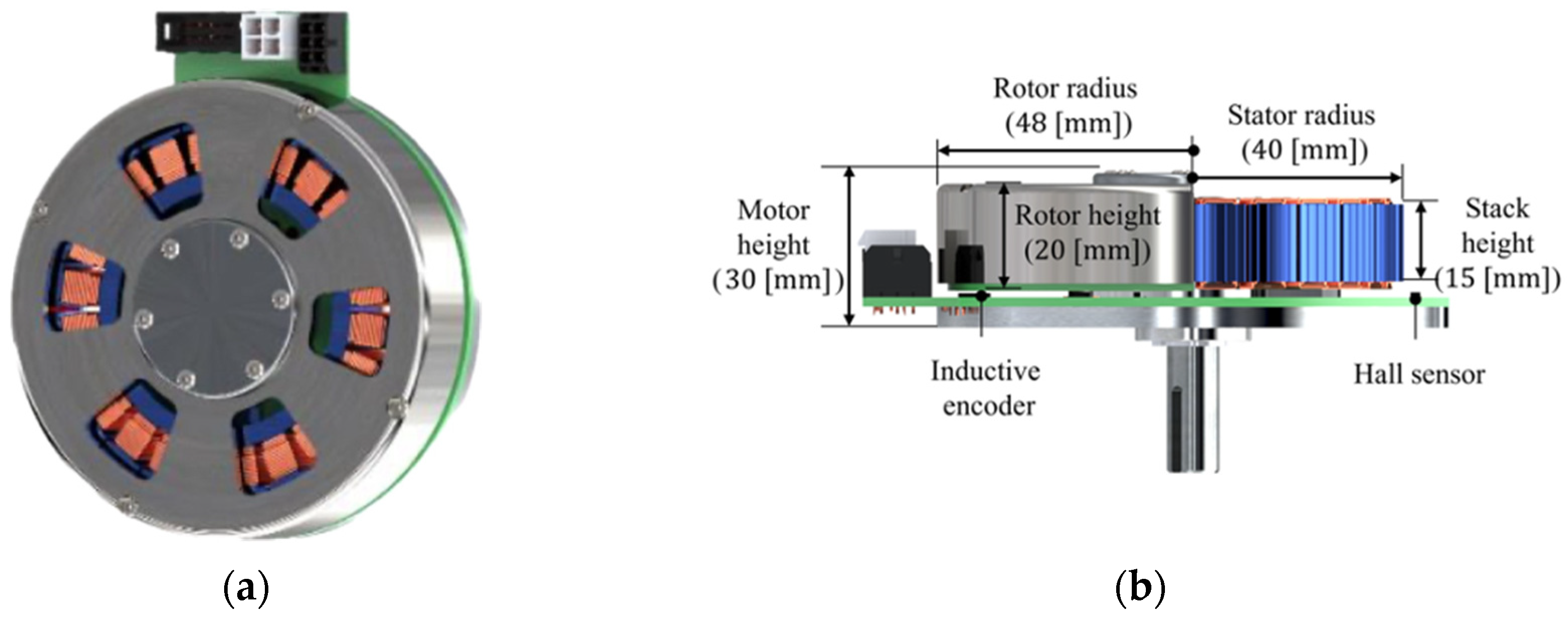
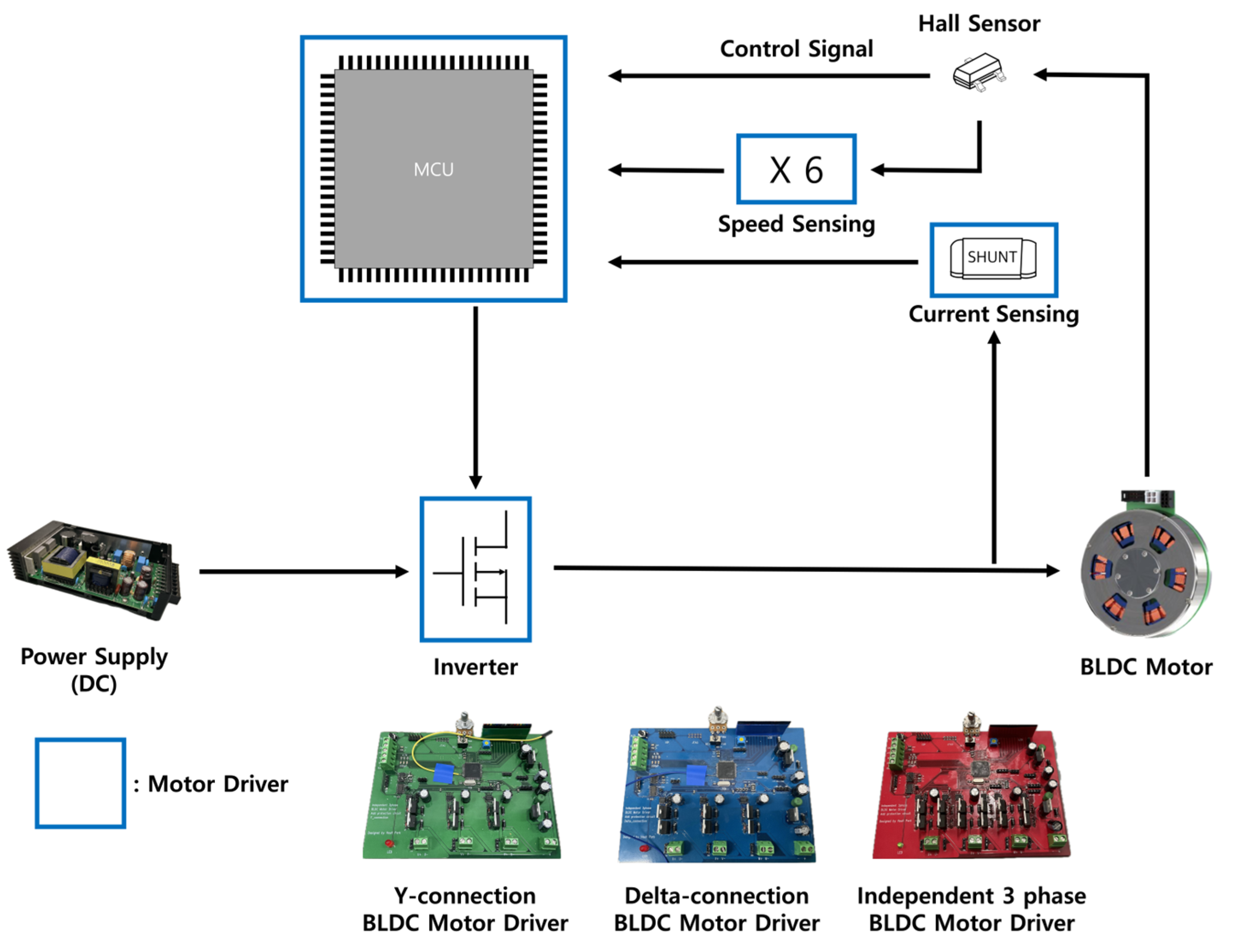
A motor optimized for high torque density was developed, as shown in Figure 1, by applying various design elements such as strong magnets, minimized air gap between the stator and rotor, along with a Halbach array to prevent flux leakage and concentrate flux on the stator. Figure 1a shows the front view of the motor, and Figure 1b presents the side view of the motor, with the right side of the shaft showing how the stator is positioned inside the motor. The mass distribution of the developed motor is presented in Table 1, and its characteristic parameters are listed in Table 2. We conducted experiments based on this developed motor with different winding structures.
2.1. Three-Phase BLDC Motor Governing Equations
The governing equations for the characteristics of Y-Connection, D-Connection, and independent three-phase motors are all the same, making it easy to compare the characteristics of each winding method using the following equations. The voltage equation is expressed as Equation (1), the output power as Equation (2), and the torque equation as Equation (3) [11,12].
Here, represents either the phase voltage or line voltage depending on the winding method of the stator, signifies the resistance of the stator, denotes the inductance of the stator, represents the phase current flowing through each of the three phases, signifies the back electromotive force generated in each phase, and represents the mechanical angular velocity of the rotor.
Here, V represents the maximum amplitude of the Back EMF, signifies the Back EMF constant, denotes the electrical angular frequency, means the continuous time. The Back EMF for each phase is represented by Equation (5), with each phase having a phase difference of .
2.2. Three-Phase BLDC Motors’ Winding Structure
For BLDC motors, different characteristics can be achieved depending on the winding structure of the stator. The Y-Connection is preferred for applications requiring high torque and low speed due to its simple structure and relatively high efficiency. On the other hand, the D-Connection is suitable for applications with low torque and high speed as it can reduce the phase impedance and widen the operating range. Especially in drive systems with an independent power supply powered by low-voltage batteries, the D-Connection is frequently used [13,14]. In contrast to the two commonly used connection methods, the approach we propose utilizes an independent three-phase method, known as the single-phase excitation structure, where voltage is applied independently to each winding without contact points between them.
In the case of the independent three-phase system’s wiring structure, there is almost no increase in the size and weight of the motor itself. Unlike the Y-Connection or D-Connection methods, where one voltage source is split into two or three phases, in the independent three-phase system, one voltage source is allocated to each phase. This results in an increase in phase voltage. This increase in phase voltage implies an increase in phase current when resistance and inductance are constant. Therefore, this increase in phase current translates into an increase in the torque that the motor can exert at the same voltage. Since the control method is generally similar to that of commonly used wiring methods, changing only the winding method presents no significant challenge. This paper validates the efficacy of the independent three-phase BLDC motor through comparative experiments with Y-Connection BLDC motors and D-Connection BLDC motors.
2.2.1. Y-Connection BLDC Motor Design
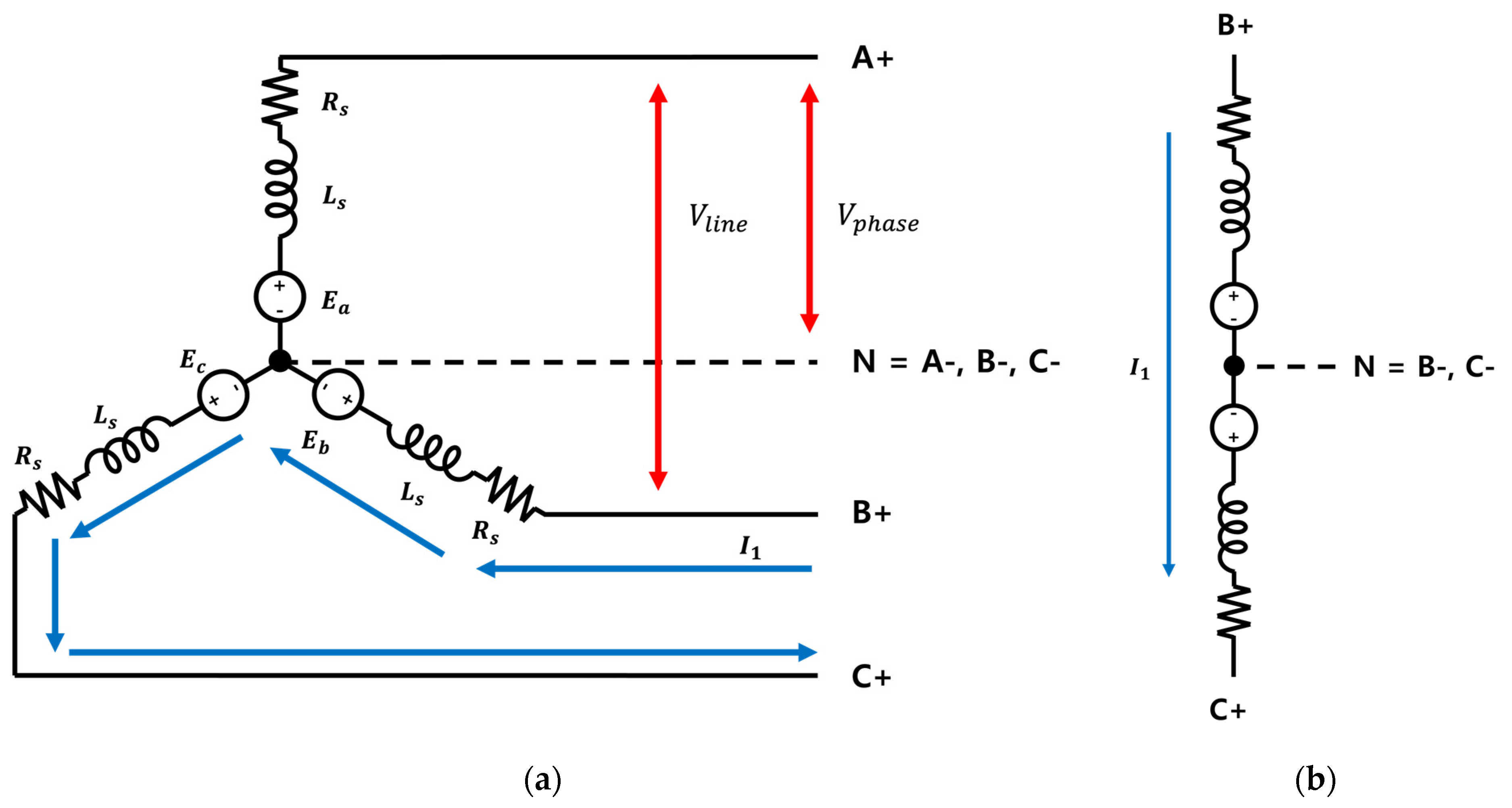
In the case of a Y-Connection BLDC motor, each of the three phases forms a neutral point, as shown in Figure 2a. The excitation structure applied to the armature is a two-phase excitation system, as depicted in Figure 2b, where two phases are excited by one voltage source. In this system, since two phases are excited by one voltage source, the available voltage per phase is reduced by half [15]. The reason why Y-connected BLDC motors are more commonly used than D-connected BLDC motors is that by not grounding the neutral point, they can remove the zero-sequence component of the third harmonic that causes inductive interference, thereby improving the waveform and reducing the effect of ripple on the BLDC motor operation. Additionally, the relationship between line-to-line voltage and phase voltage is advantageous for high voltages, and corona discharge and deterioration are prevented.
Here, represents the line-to-line voltage, represents the phase voltage, represents the line current, and represents the phase current. In the case of Y-Connection, the line-to-line voltage is times greater than the phase voltage. The motor reaches saturation speed at where Equation (9) is satisfied [16].
2.2.2. D-Connection BLDC Motor Design
In the case of D-Connection BLDC motors, one end of each winding is connected to the neighboring end of the adjacent winding, creating a total of three winding junctions, as shown in Figure 3a. When voltage is applied to the stator, as illustrated in Figure 3b, it forms a three-phase excitation system where all three phases are energized by a single voltage source [15]. With this system, all three phases are excited by a single voltage source. The uneven distribution of voltage applied to each phase, as seen in Figure 3b, creates ripples in the operation of the BLDC motor [17].
In the case of D-Connection, the line-to-line voltage is equal to the phase voltage, while the line current is times greater than the phase voltage. The motor reaches saturation speed at where Equations (13) and (14) are satisfied; compared to Equation (9) for the Y-Connection BLDC motor, it has a saturation point that is times higher [16].
2.2.3. Independent Three-Phase BLDC Motor Design
In the independent three-phase BLDC motor, unlike Y-Connection and D-Connection methods, each phase is separate and distinct without any junction points, as illustrated in Figure 4a. Additionally, the electrical location of each phase in the motor’s structure is identical to that of the Y-Connection and D-Connection methods. This adds no complexity to motor control and facilitates easy handling. In the independent three-phase BLDC motor, unlike the previous methods, when voltage is applied to one phase, it is exclusively applied to that phase. The voltage is not distributed among the other phases. The increase in applied voltage signifies an increase in phase current when the resistance and inductance of the stator remain constant, as indicated by Equation (3), leading to an increase in torque [12].
In the case of the independent three-phase BLDC motor, unlike the Y-Connection BLDC motor and D-Connection BLDC motor, there is no difference in the magnitudes of line voltage and phase voltage as well as line current and phase current. The speed of the BLDC motor saturates at ω, which satisfies Equation (15).
2.3. Three-Phase BLDC Motor Inverters Design
2.3.1. Y-Connection and D-Connection BLDC Motor Inverter Design
The inverter structure for both Y-Connection and D-Connection BLDC motors, as shown in Figure 5, is identical. It utilizes six switching components for driving the motor and comprises three half-bridge inverters. In the Y-Connection configuration, as depicted in Figure 5, junctions are formed by A-, B-, and C-. Additionally, A+, B+, and C+ are each connected to their respective half-bridge inverters. Conversely, for D-Connection, A+B-, B+C-, and C+A- form the junctions, connecting to the corresponding parts of the half-bridge inverter. The control sequence based on Hall Sensor signals, which is illustrated in Table 3, remains the same for both wiring configurations [18]. In the Table 3 and Table 4, the upward arrow represents when the Hall sensor turns on, and the downward arrow represents when the Hall sensor turns off.
2.3.2. Independent Three-Phase BLDC Motor Inverter Design
Unlike the six-step inverters of Y-Connection BLDC motors and D-Connection BLDC motors, the inverter structure of the independent three-phase BLDC motor, as shown in Figure 6, consists of three full-bridge inverters, with each full-bridge inverter controlling the switching on/off of one phase. The connection between the stator and a single pole in the inverter is illustrated in Figure 6. Furthermore, the independent three-phase BLDC motor has an identical electrical location with Y-Connection BLDC motors and D-Connection BLDC motors. As a result, controlling the signal output based on the Hall Sensor signals is easily achievable using the same Hall Sensor signals as shown in Table 4 [19].
3. Experiment Comparing the Motor Dynamics
3.1. Experiment Design and Parameters
The proposed experiment’s overall layout and experimental test bed are depicted in Figure 7 and Figure 8. The aim of experiments is to compare the dynamic characteristics of Y-Connection BLDC motors, D-Connection BLDC motors, and independent three-phase BLDC motors to determine which winding structure is most suitable for robot joint actuators. To prevent variations in motor parameters due to changes in coil length based on the motor’s wiring junctions, the junctions for Y-Connection and D-Connection were made within the motor driver’s PCB. The parameters of the BLDC motors, including the stator resistance, the rated voltage is 24 V, and the switching frequency is 18 kHz. Speed calculation was performed using Hall sensor signals, and current measurement was performed using shunt resistors located at the bottom of the motor driver’s inverter.
3.2. Speed Experiment of Each BLDC Motor
The speed was calculated using the M method, using signals from the Hall sensors that were amplified sixfold to increase resolution. The equations for the M method are as provided in (18) and (19), and the parameters used for speed calculation are detailed in Table 5 [20]. The first comparative analysis of motor dynamics was conducted with PWM ranging from 30% to 90%, measuring the RPM changes corresponding to each duty ratio. In the second comparative analysis experiment, the characteristics of speed and current were compared at a 90% duty ratio.
Here, represents the rotation angle, signifies the time, poles indicate the number of poles in the motor, and PPR (Pulse Per Revolution) refers to the maximum number of output pulses per revolution of the motor. represents the sampling time, denotes the number of pulses per sampling time.
4. Results
In the first dynamic characteristic comparison experiment, the change in speed with respect to the change in duty ratio from 30% to 90% is shown in Figure 9. As shown in Section 2, in the case of the independent three-phase BLDC motor, which is a single-phase excitation system, since one voltage source can be used entirely by one phase, it can be seen that it achieves a higher speed at the same duty ratio. In the experiment, it was confirmed that noise and vibration, which did not occur in the independent three-phase BLDC motor and Y-Connection BLDC motor, occurred in the D-Connection BLDC motor. This can be attributed to the third harmonic present in the D-Connection and the imbalance of the voltage applied to each phase.
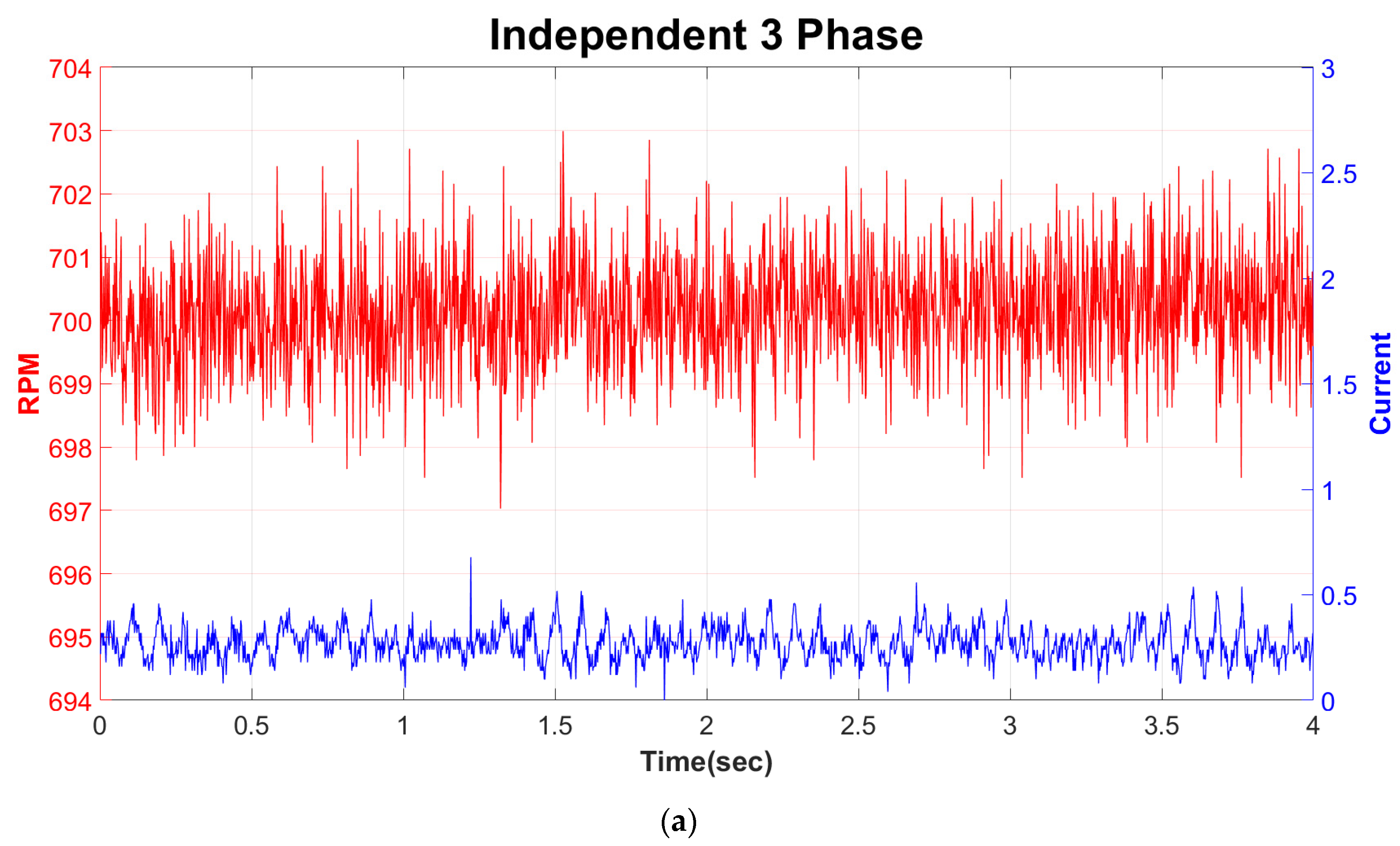
The second dynamic characteristic comparison experiment is shown in Figure 10, and the average speed and current were measured at a 90% duty ratio. Figure 10a shows the speed and current data of the independent three-phase BLDC motor, with an average speed of 700.1412 RPM and an average current value of 0.2707 A. The maximum current value was measured as 0.6780 A, confirming that a current ripple of approximately 0.4 A occurred at maximum current value. Figure 10b shows the Y-Connection BLDC motor, with an average speed of 368.1172 RPM and an average current value of 0.1218 A. The maximum current value was 0.3589 A, and the current ripple was confirmed to be approximately 0.2471 A. Comparing the data of these two winding structures, it can be confirmed that the independent three-phase BLDC motor, which is a single-phase excitation system, has an average speed value about twice as high as the Y-Connection BLDC motor, which is a two-phase excitation system. As described in Section 2, this value is similar to the theory that the independent three-phase BLDC motor, which uses the full voltage in each phase, shows twice the speed compared to the Y-Connection BLDC motor, which uses half of the total voltage in each phase. Figure 10c shows the D-Connection BLDC motor, with an average speed measured as 613.4125 RPM, and the average current value and maximum current value measured as 0.2430 A and 1.3588 A, respectively. Therefore, the maximum ripple is 1.1158 A. It can be confirmed that the average speed shows a saturation speed about √3 times higher compared to the Y-Connection BLDC motor, as shown in the theory. It can also be observed that the current values flowing in each phase are different, and the higher ripple current measured can be attributed to the imbalance in the voltage across each phase and the presence of the third harmonic.
5. Discussion
Through a comparative analysis of motor characteristics, we sought to determine the most suitable wiring structure for BLDC motors in robot joint actuators. Our investigation compared the commonly used Y-Connection and D-Connection methods with the independent three-phase BLDC motor, which controls three distinct phases without junctions.
As shown in Figure 9, it was confirmed that the independent three-phase BLDC motor achieved the highest speed in all regions as the duty ratio increased from 30% to 90%. Additionally, as outlined in Table 6 in experiments comparing speed and current under identical voltage and duty ratios, the speed output exhibited the following trend: independent three-phase BLDC motor > D-Connection BLDC motor > Y-Connection BLDC motor. Moreover, comparing the independent three-phase BLDC motor with the Y-Connection BLDC motor, the former exhibited approximately 1.9-times-higher speed, even though it had a value about 4.9% lower than the theoretical value. Similarly, in comparing the Y-Connection BLDC motor with the D-Connection BLDC motor, the latter showed a speed approximately 1.67 times higher, yet about 3.79% lower than the theoretical value of times the speed saturation point. Additionally, comparing the independent three-phase BLDC motor with the D-Connection BLDC motor, while theoretically both types of motors should have the same saturation speed, experimental results revealed that the independent three-phase BLDC motor had a speed of about 86.73 RPM, which is 1.14 times higher. Therefore, these speed characteristic comparison results demonstrate that the speed characteristics of the motor can be improved by changing the winding structure of the motor.
The average current values adhere to the following sequence: independent three-phase BLDC motor > D-Connection BLDC motor > Y-Connection BLDC motor. However, there is a minimal difference in the average current values between the independent three-phase BLDC motor and the D-Connection BLDC motor, with a variance of approximately 0.03 A. Furthermore, as depicted in Figure 10, the D-Connection BLDC motor exhibits ripple currents five times larger than the average current, marking it as the motor with the highest current ripple among the three types. This can be attributed to the influence of the third harmonic in D-Connection BLDC motors and the imbalance in voltage across phases. Motors generating significant ripple currents also tend to exhibit corresponding torque ripple, making them challenging for use in robotic joints. Therefore, upon examining the results, it becomes evident that the current characteristics of the independent three-phase BLDC motor are superior to those of the D-Connection BLDC motor.
Through the above comparison of speed and current characteristics, it was shown that the independent three-phase BLDC motor can compensate for the disadvantages of high-torque-density motors. Consequently, this application can promote the use of high-torque-density motors in the actuators of robots that physically interact with humans. Furthermore, when high-torque-density motors are applied to robot joints, the lower gear dependency can lead to the reduction in nonlinear friction, enabling the estimation of torque from the motor current and eliminating the need for torque sensors. Moreover, wearable robots, walking robots, and other robots that require batteries should have excellent characteristics at low voltages due to the size and weight limitations of battery packs. In this regard, the independent three-phase BLDC motor has an additional advantage, as it exhibits the best dynamic characteristics at the same voltage compared to other motor types. These contributions lead to a reduction in joint volume and weight, as well as a decrease in manufacturing costs, and this cycle greatly contributes to the advancement of robots.
However, there are several drawbacks to using an independent three-phase BLDC motor. Firstly, it may not be widely available on the market compared to Y-Connection and D-Connection BLDC motors, along with the difficulty in obtaining independent three-phase BLDC motor drivers. Secondly, the need of twice as many switching components in the inverter compared to conventional six-step inverters leads to a doubling of switching losses. Although losses due to switching components increase linearly, losses due to Joule heating increase quadratically with current, making it advantageous to minimize losses caused by Joule heating. Despite these drawbacks, increasing motor torque density remains essential for addressing the fundamental challenges in the development of robots that physically interact with humans. It is anticipated to contribute significantly to overcoming existing stagnation in the robotics industry and advancing human–robot interaction capabilities.
In the future work, to achieve significantly higher torque density and high speed within the robotic actuators themselves, we will develop multi-phase independent motors and motor drivers based on the independent three-phase BLDC motor. Afterward, we will apply these advancements to robotic joints and secure back-drivability to enhance both performance and safety in physical human–robot interaction. These advancements will contribute to the research field of safe physical interaction between humans and robots.
Author Contributions
Conceptualization, J.P. and H.C.; methodology, J.P. and H.C.; software, J.P.; data curation, J.P. and H.C.; formal analysis, J.P. and H.C.; writing—original draft preparation, J.P.; writing—review and editing, J.P. and H.C.; supervision, H.C.; project administration, H.C.; funding acquisition, H.C. All authors have read and agreed to the published version of the manuscript.
Funding
This work was supported by Incheon National University (International Cooperative) Research Grant in 2019.
Data Availability Statement
Data are contained within the article.
Conflicts of Interest
The authors declare no conflicts of interest.
References
- Pervez, A.; Ryu, J. Safe physical human robot interaction-past, present and future. J. Mech. Sci. Technol. 2008, 22, 469–483. [Google Scholar] [CrossRef]
- Suzumori, K.; Faudzi, A.A. Trends in hydraulic actuators and components in legged and tough robots: A review. Adv. Robot. 2018, 32, 458–476. [Google Scholar] [CrossRef]
- Ali, H.I.; Noor, S.B.B.M.; Bashi, S.M.; Marhaban, M.H. A review of pneumatic actuators (modeling and control). Aust. J. Basic Appl. Sci. 2009, 3, 440–454. [Google Scholar]
- Seok, S.; Wang, A.; Otten, D.; Kim, S. Actuator design for high force proprioceptive control in fast legged locomotion. In Proceedings of the 2012 IEEE/RSJ International Conference on Intelligent Robots and Systems, Vilamoura, Portugal, 7–12 October 2012; pp. 1970–1975. [Google Scholar]
- Seok, S.; Wang, A.; Chuah, M.Y.M.; Otten, D.; Lang, J.; Kim, S. Design principles for highly efficient quadrupeds and implementation on the MIT Cheetah robot. In Proceedings of the 2013 IEEE International Conference on Robotics and Automation, Karlsruhe, Germany, 6–10 May 2013; pp. 3307–3312. [Google Scholar]
- Seok, S.; Wang, A.; Chuah, M.Y.; Hyun, D.J.; Lee, J.; Otten, D.M.; Lang, J.H.; Kim, S. Design principles for energy-efficient legged locomotion and implementation on the MIT cheetah robot. IEEE ASME Trans. Mechatron. 2014, 20, 1117–1129. [Google Scholar] [CrossRef]
- Wensing, P.M.; Wang, A.; Seok, S.; Otten, D.; Lang, J.; Kim, S. Proprioceptive actuator design in the MIT cheetah: Impact mitigation and high-bandwidth physical interaction for dynamic legged robots. IEEE Trans. Robot. 2017, 33, 509–522. [Google Scholar] [CrossRef]
- Farve, N.N. Design of a Low-Mass High-Torque Brushless Motor for Application in Quadruped Robotics. Ph.D. Thesis, Massachusetts Institute of Technology, Cambridge, MA, USA, 2012. [Google Scholar]
- Yu, S.; Wang, Z.; Gan, H.; Shi, Q.; Wang, Z.; Xiao, Y.; Zhang, J.; Zhao, J. Quasi-direct drive actuation for a lightweight hip exoskeleton with high backdrivability and high bandwidth. IEEE ASME Trans. Mechatron. 2020, 25, 1794–1802. [Google Scholar] [CrossRef] [PubMed]
- Jo, K.-J.; Oh, J.-S. Characteristic analysis of independent 3 phase BLDC motor. Trans. Korean Inst. Power Electron. 2007, 12, 299–304. [Google Scholar]
- Pillay, P.; Krishnan, R. Modeling of permanent magnet motor drives. IEEE Trans. Ind. Electron. 1988, 35, 537–541. [Google Scholar] [CrossRef]
- Pillay, P.; Krishnan, R. Modeling, simulation, and analysis of permanent-magnet motor drives. II. The brushless DC motor drive. IEEE Trans. Ind. Appl. 1989, 25, 274–279. [Google Scholar] [CrossRef]
- Mohanraj, D.; Muthananthguruadoss, S.; Vijayarajan, A.; Rajasekar, V.G.; Chokkalingam, B.; Muthuramalingam, T. A review of BLDC motor: State of art, advanced control techniques, and applications. IEEE Access 2022, 10, 54833–54869. [Google Scholar] [CrossRef]
- Park, D.-H.; Chun, Y.-H.; Lee, K.-H.; Koo, B.-K. Current Compensation Scheme to Reduce Torque Ripples of Delta-connected Low-inductance BLDC Motor Drives. Trans. Korean Inst. Power Electron. 2017, 22, 449–456. [Google Scholar]
- Kim, Y.; Yoon, Y.-D.; Sul, S.-K. Design and control methodology analysis of BLDC motor for torque ripple minimization considering winding connection. In Proceedings of the 2013 International Conference on Electrical Machines and Systems (ICEMS), Busan, Republic of Korea, 26–29 October 2013; pp. 1138–1141. [Google Scholar]
- Heo, C.-N.; Hwang, S.-H. Air-gap Control According to Y and Delta Connections of Double-sided Air-gap Permanent Magnet Synchronous Motor with Independent Three-phase Structure. Trans. Korean Inst. Power Electron. 2017, 22, 249–255. [Google Scholar]
- Lee, T.-Y.; Chun, Y.-H.; Ahn, J.-M.; Lee, J.; Chun, T.-W. Design and torque ripple analysis of brush-less dc motor according to delta winding connection. J. Magn. 2015, 20, 166–175. [Google Scholar] [CrossRef]
- Lee, Y.; Kim, J. Analysis of the three-phase inverter power efficiency of a BLDC motor drive using conventional six-step and inverted pulsewidth modulation driving schemes. Can. J. Electr. Comput. Eng. 2019, 42, 34–40. [Google Scholar] [CrossRef]
- Sun, Q.; Wu, J.; Gan, C.; Si, J.; Guo, Y. Modular full-bridge converter for three-phase switched reluctance motors with integrated fault-tolerance capability. IEEE Trans. Power Electron. 2018, 34, 2622–2634. [Google Scholar] [CrossRef]
- Petrella, R.; Tursini, M.; Peretti, L.; Zigliotto, M. Speed measurement algorithms for low-resolution incremental encoder equipped drives: A comparative analysis. In Proceedings of the 2007 International Aegean Conference on Electrical Machines and Power Electronics, Bodrum, Turkey, 10–12 September 2007; pp. 780–787. [Google Scholar]
Figure 1.
(a) Developed motor’s front view; (b) developed motor’s side view.

Figure 2.
(a) Equivalent circuit of Y-connection BLDC motor; (b) excitation system of Y-connection BLDC motor (2-phase excitation).
Figure 2.
(a) Equivalent circuit of Y-connection BLDC motor; (b) excitation system of Y-connection BLDC motor (2-phase excitation).

Figure 3.
(a) Equivalent circuit of D-Connection BLDC motor; (b) excitation system of D-Connection BLDC motor (3-phase excitation).
Figure 3.
(a) Equivalent circuit of D-Connection BLDC motor; (b) excitation system of D-Connection BLDC motor (3-phase excitation).

Figure 4.
(a) Equivalent circuit of independent 3-phase BLDC motor; (b) excitation system of independent 3-phase BLDC motor (single-phase excitation).
Figure 4.
(a) Equivalent circuit of independent 3-phase BLDC motor; (b) excitation system of independent 3-phase BLDC motor (single-phase excitation).

Figure 5.
Y-Connection and D-Connection BLDC motor inverter circuit and connecting schematic.

Figure 6.
Independent 3-phase BLDC motor inverter circuit and connecting schematic.

Figure 7.
Experiment setup schematic.

Figure 8.
Top view of the experimental test bed.

Figure 9.
Comparison of motor speeds at PWM Duty 30~90%.

Figure 10.
(a) Independent three-phase BLDC motor RPM and current at PWM Duty 90%; (b) Y-Connection BLDC motor RPM and current at PWM Duty 90%; (c) D-Connection BLDC motor RPM and current at PWM Duty 90%.
Figure 10.
(a) Independent three-phase BLDC motor RPM and current at PWM Duty 90%; (b) Y-Connection BLDC motor RPM and current at PWM Duty 90%; (c) D-Connection BLDC motor RPM and current at PWM Duty 90%.


Table 1.
Mass distribution of the developed motor.
| Parameters of Motors | Rotor (Magnet and Yoke) | Rotor (Housing and Axis) | Stator | Stator Housing | Bearing and PCB | Total Mass (Frameless) | Total Mass (Housed) |
|---|---|---|---|---|---|---|---|
| Unit [g] | 150 | 80 | 280 | 55 | 30 | 430 | 595 |
Table 2.
Developed motor characteristic parameters (Y-Connection winding structure).
| Parameters Motors | Torque Const. [Nm/A] | Phase Resistance [Ω] | Motor Const. ] | Nominal Torque [Nm] | Cogging Torque [Nm] | Continuous Torque Density (Frameless) [Nm/kg] | Continuous Torque Density (Housed) [Nm/kg] |
|---|---|---|---|---|---|---|---|
| Developed Motor | 0.755 | 0.717 | 0.630 | 3.45 | 0.021 | 8.03 | 5.81 |
Table 3.
Y-Connection and D-Connection BLDC motor hall sensor and phase sequence. (The upward arrow represents when the Hall sensor turns on, and the downward arrow represents when the Hall sensor turns off).
Table 3.
Y-Connection and D-Connection BLDC motor hall sensor and phase sequence. (The upward arrow represents when the Hall sensor turns on, and the downward arrow represents when the Hall sensor turns off).
| Direction | Operating Range | Hall Sensor | Switching Signal | ||||||||
|---|---|---|---|---|---|---|---|---|---|---|---|
| Degree | Interrupt | HA | HB | HC | A1 | A2 | B1 | B2 | C1 | C2 | |
| Forward | 0~60 | HA↑ | 1 | 0 | 1 | 1 | 0 | 0 | PWM | 0 | 0 |
| 60~120 | HC↓ | 1 | 0 | 0 | 1 | 0 | 0 | 0 | 0 | PWM | |
| 120~180 | HB↑ | 1 | 1 | 0 | 0 | 0 | 1 | 0 | 0 | PWM | |
| 180~240 | HA↓ | 0 | 1 | 0 | 0 | PWM | 1 | 0 | 0 | 0 | |
| 240~300 | HC↑ | 0 | 1 | 1 | 0 | PWM | 0 | 0 | 1 | 0 | |
| 300~360 | HB↓ | 0 | 0 | 1 | 0 | 0 | 0 | PWM | 1 | 0 | |
| Reverse | 0~60 | HA↑ | 1 | 1 | 0 | 0 | 0 | 0 | PWM | 1 | 0 |
| 60~120 | HB↓ | 1 | 0 | 0 | 0 | PWM | 0 | 0 | 1 | 0 | |
| 120~180 | HC↑ | 1 | 0 | 1 | 0 | PWM | 1 | 0 | 0 | 0 | |
| 180~240 | HA↓ | 0 | 0 | 1 | 0 | 0 | 1 | 0 | 0 | PWM | |
| 240~300 | HB↑ | 0 | 1 | 1 | 1 | 0 | 0 | 0 | 0 | PWM | |
| 300~360 | HC↓ | 0 | 1 | 0 | 1 | 0 | 0 | PWM | 0 | 0 | |
Table 4.
Independent 3-phase BLDC motor hall sensor and phase sequence. (The upward arrow represents when the Hall sensor turns on, and the downward arrow represents when the Hall sensor turns off).
Table 4.
Independent 3-phase BLDC motor hall sensor and phase sequence. (The upward arrow represents when the Hall sensor turns on, and the downward arrow represents when the Hall sensor turns off).
| Direction | Operating Range | Hall Sensor | Switching Signal | ||||||||||||||
|---|---|---|---|---|---|---|---|---|---|---|---|---|---|---|---|---|---|
| Degree | Interrupt | HA | HB | HC | A1 | A2 | A3 | A4 | B1 | B2 | B3 | B4 | C1 | C2 | C3 | C4 | |
| Forward | 0~60 | HA↑ | 1 | 0 | 1 | 1 | 0 | 0 | PWM | 0 | PWM | 1 | 0 | 0 | 0 | 0 | 0 |
| 60~120 | HC↓ | 1 | 0 | 0 | 1 | 0 | 0 | PWM | 0 | 0 | 0 | 0 | 0 | PWM | 1 | 0 | |
| 120~180 | HB↑ | 1 | 1 | 0 | 0 | 0 | 0 | 0 | 1 | 0 | 0 | PWM | 0 | PWM | 1 | 0 | |
| 180~240 | HA↓ | 0 | 1 | 0 | 0 | PWM | 1 | 0 | 1 | 0 | 0 | PWM | 0 | 0 | 0 | 0 | |
| 240~300 | HC↑ | 0 | 1 | 1 | 0 | PWM | 1 | 0 | 0 | 0 | 0 | 0 | 1 | 0 | 0 | PWM | |
| 300~360 | HB↓ | 0 | 0 | 1 | 0 | 0 | 0 | 0 | 0 | PWM | 1 | 0 | 1 | 0 | 0 | PWM | |
| Reverse | 0~60 | HA↑ | 1 | 1 | 0 | 0 | 0 | 0 | 0 | 0 | PWM | 1 | 0 | 1 | 0 | 0 | PWM |
| 60~120 | HB↓ | 1 | 0 | 0 | 0 | PWM | 1 | 0 | 0 | 0 | 0 | 0 | 1 | 0 | 0 | PWM | |
| 120~180 | HC↑ | 1 | 0 | 1 | 0 | PWM | 1 | 0 | 1 | 0 | 0 | PWM | 0 | 0 | 0 | 0 | |
| 180~240 | HA↓ | 0 | 0 | 1 | 0 | 0 | 0 | 0 | 1 | 0 | 0 | PWM | 0 | PWM | 1 | 0 | |
| 240~300 | HB↑ | 0 | 1 | 1 | 1 | 0 | 0 | PWM | 0 | 0 | 0 | 0 | 0 | PWM | 1 | 0 | |
| 300~360 | HC↓ | 0 | 1 | 0 | 1 | 0 | 0 | PWM | 0 | PWM | 1 | 0 | 0 | 0 | 0 | 0 | |
Table 5.
Speed calculation parameters for the M method.
| Number of Poles | PPR | Ts (Sampling Time) [s] | |
|---|---|---|---|
| BLDC motor | 26 | 78 | 0.04 |
Table 6.
Mean RPM, mean current and max ripple current at PWM Duty 90%.
| Independent 3-Phase | Y-Connection | D-Connection | |
|---|---|---|---|
| RPM | 700.1412 | 368.1172 | 613.4125 |
| Current [A] | 0.2707 | 0.1218 | 0.2430 |
| Max Ripple [A] | 0.6780 | 0.3589 | 1.3558 |
Disclaimer/Publisher’s Note: The statements, opinions and data contained in all publications are solely those of the individual author(s) and contributor(s) and not of MDPI and/or the editor(s). MDPI and/or the editor(s) disclaim responsibility for any injury to people or property resulting from any ideas, methods, instructions or products referred to in the content. |
© 2024 by the authors. Licensee MDPI, Basel, Switzerland. This article is an open access article distributed under the terms and conditions of the Creative Commons Attribution (CC BY) license (https://creativecommons.org/licenses/by/4.0/).
Share and Cite
MDPI and ACS Style
Park, J.; Chang, H. Improving Speed Characteristics of High-Torque-Density Motors for Physical Human–Robot Interaction Using an Independent Three-Phase Winding Structure. Actuators 2024, 13, 161. https://doi.org/10.3390/act13050161
AMA Style
Park J, Chang H. Improving Speed Characteristics of High-Torque-Density Motors for Physical Human–Robot Interaction Using an Independent Three-Phase Winding Structure. Actuators. 2024; 13(5):161. https://doi.org/10.3390/act13050161
Chicago/Turabian StylePark, Junghwan, and Handdeut Chang. 2024. "Improving Speed Characteristics of High-Torque-Density Motors for Physical Human–Robot Interaction Using an Independent Three-Phase Winding Structure" Actuators 13, no. 5: 161. https://doi.org/10.3390/act13050161
Note that from the first issue of 2016, this journal uses article numbers instead of page numbers. See further details here.