Experimental Research on Dynamic Characteristics of a Multi-Disc Rotor System Supported by Aerostatic Bearings


1
School of Power and Energy, Northwestern Polytechnical University, Xi’an 710072, China
2
AECC Hunan Aviation Powerplant Research Institute, Zhuzhou 412002, China
3
TaiHang Laboratory, Chengdu 610299, China
4
School of Mechanical Engineering, Jiangsu Ocean University, Lianyungang 222005, China
5
Institute of Engineering Thermophysics, Chinese Academy of Sciences, Beijing 100190, China
6
Institute of New Energy, Dongguan 523808, China
*
Author to whom correspondence should be addressed.
Lubricants 2024, 12(5), 151; https://doi.org/10.3390/lubricants12050151
Submission received: 21 March 2024
/
Revised: 16 April 2024
/
Accepted: 23 April 2024
/
Published: 27 April 2024
(This article belongs to the Special Issue Gas Lubrication and Dry Gas Seal)
Abstract
:Gas bearings have the advantages of small friction loss, wide applicable speed range, no pollution, etc., and have important application prospects in micro and small high-speed rotating machinery. However, due to its compressibility and low viscosity, its dynamic stability in high-speed rotating machinery is the key to constraining its development. The experimental study of shaft system dynamics is the main means to explore the mechanism of rotor behavior. On the test platform of dynamic characteristics of multi-disc rotor system supported by aerostatic bearings, experimental research on the nonlinear dynamic characteristics of a rotor system was carried out, and nonlinear vibration test and analysis methods, such as axial orbits, bifurcation diagrams, and spectral characteristics, were adopted, and vibration phenomena, including the critical rotational speed accumulating energy and low-frequency accumulating energy, were presented and the vibration characteristics of bearing fracture faults were presented. The bearing supply pressure and rubber damping pad were introduced as a method to suppress the low-frequency vibration of the aerostatic bearing rotor system, and its vibration-reduction effect was verified by experiments. The above results can provide technical support for vibration control and fault diagnosis of rotor systems supported by aerostatic bearings.
1. Introduction
Gas bearings are a sliding bearing lubricating medium with low viscosity and small changes with temperature, clean and pollution-free characteristics, radiation resistance, compressibility, and other gas characteristics. Due to their advantages of low power consumption, long life, and high precision, they have good application advantages in the fields of high-speed support, high-precision support, and support under special working conditions [1,2]. However, the low viscosity and compressibility of air lead to nonlinear vibration and dynamic instability in high-speed rotating machinery [3]. Researchers have devoted much effort to hydrostatic gas bearing performance enhancement and dynamic performance prediction of bearing–rotor systems.
Feng et al. [4] proposed a novel aerostatic bearing with damper modules to suppress the vibration on the bearing’s surface. By theoretical and experimental investigations, aerostatic bearings with a hermetically sealed squeeze-film damper can provide better performance in terms of damping and stability. Moreover, Li et al. [5] proposed a novel multi-objective optimization design method for quickly and efficiently designing ideal micro-hole aerostatic bearings with both the maximum load capacity and stiffness being large. The effectiveness of the optimization design method was verified by comparing theoretical and experimental data. Feng et al. [6,7] proposed a new perspective to identify the characteristics of a pneumatic hammer by comparing the predicted results and the experimental measurements. The results showed that the pneumatic hammer with aerostatic bearings relied on the frequency characteristics between the natural frequency of the bearing–load system and pressure fluctuation frequency in the recess. Gao et al. [8] proposed a finite-element method based on the fluid–structure interaction modeling method for the design of aerostatic thrust bearing. The accuracy of the proposed fluid–structure interaction model was verified numerically and experimentally. Yu et al. [9] introduced a novel design featuring a multiple-inclined-orifice restrictors to address the challenge of turbulent vortices and reducing nano-vibrations in aerostatic bearings. Meanwhile, load-carrying capacity and vibration tests were conducted on aerostatic bearings equipped with multiple-inclined-orifice restrictors to validate the proposed model’s accuracy and assess the effectiveness of multiple-inclined-orifice restrictor. Li et al. [10] investigated the lubrication mechanism and characteristics of aerostatic bearings with close-spaced micro holes, which could improve load capacity by over 22% and maximum stiffness by over 32% compared with aerostatic bearings with inherent orifices. Maamari et al. [11] presented a dynamic model encapsulating the fluid–structure interaction to investigate the damping characteristics of bearings with structural compliance. A dynamic model encapsulating the fluid–structure interaction was established by experimental analysis to validate the model and sensitivity analysis.
Scholars have carried out a large number of theoretical and experimental studies on the dynamic stability of gas bearing-rotor systems. Wang et al. [12] established a bidirectional fluid-structure coupling dynamic model to analyze the dynamic properties of high-speed aerostatic journal bearing with recess. The influences of operating parameters on the coupling system are analyzed theoretically and experimentally based on the axis orbit of the rotor center, Poincare map, time response of rotor, frequency spectrum, mass flow rate, and bifurcation diagram. Yang et al. [13] researched the non-linear stability of the finite-length self-acting gas journal by solving a time-dependent Reynolds equation using the finite difference method. Zhang et al. carried out research on the throttle hole characteristics of hydrostatic gas bearings [14]. Furthermore, the FDM method was used to solve the steady-state Reynolds equations and perturbation Reynolds equations to obtain the static and dynamic characteristics of the hydrostatic gas bearings [15]. In particular, a study on the influence law of journal tilt on the static and dynamic characteristics of hydrostatic gas bearings was carried out. In addition, the nonlinear dynamics of the hydrostatic gas bearing–rotor system were investigated experimentally [16]. Shi et al. carried out an in-depth study on micro-milling with an aerostatic spindle. Experiments were conducted to measure the cutting tool displacements under stationary and rotational conditions. The results showed that the variation in the dynamic coefficients played a significant role in the spindle dynamics when the force magnitude increased beyond a critical value [17]. Chatter stability analysis in micro-milling with an aerostatic spindle considering the speed effect and the effects of supply air pressure and air film thickness on the SLD were investigated comprehensively [18]. The static and dynamic characteristics of aerostatic thrust bearings with an orifice restrictor were analyzed by solving the coupled perturbation Reynolds equations considering the interaction [19]. Yang et al. systematically investigated the nonlinear dynamic characteristics of the aerostatic bearing–rotor system, provided a series of experimental measures for nonlinear vibration control of the rotor [20,21], and proposed a coupled frequency modulation technique for the shaft system with the engineering stability discrimination criterion [22].
Although scholars have carried out a large number of theoretical and experimental studies on the characterization of gas bearings and bearing–rotor systems, dynamic analyses combined with practical application scenarios are scarce, and relevant experimental studies are even more scarce. In recent years, the application of gas bearings has expanded into more areas, including the field of ocean temperature difference power generation [23], hydrogen turbine expander bearing–rotor system dynamics in the field of hydrogen liquefaction [24,25], hydrogen fuel cell vehicles [26,27], and hydrostatic gas bearing–rotor system dynamics in electric spindles [28,29]. The parameters affecting the sensitivity of the stability of the shaft system need to be considered by experiments.
In this study, the nonlinear dynamic phenomena of the shaft system, such as the critical speed energy storage and low-frequency energy storage, are experimentally investigated on the test platform of the dynamic characteristics of the multi-disc rotor system supported by aerostatic bearings, and the causes of the bearing fracture failures are presented by combining with the rotor frequency spectrum and the shaft orbit characteristics so as to provide experimental support for the subsequent development of the high-speed power unit supported by aerostatic bearings.
2. Test Bench for Multi-Disc Rotor Systems Supported by Aerostatic Bearings
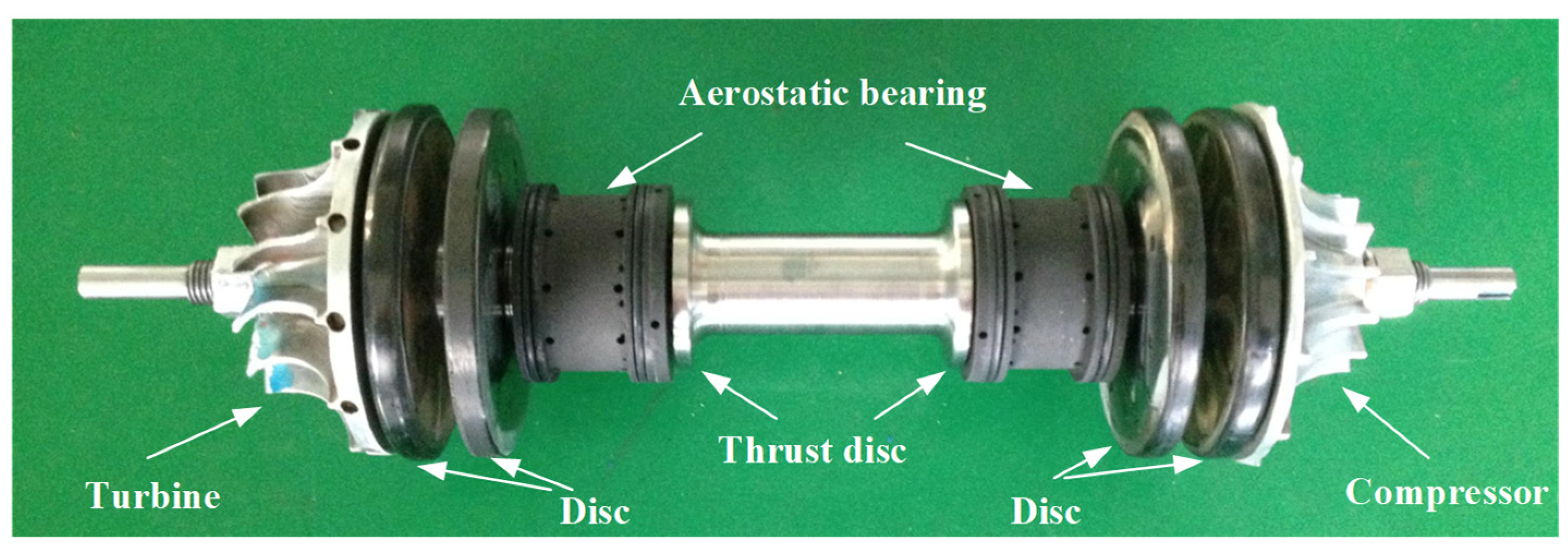
The test was conducted on the multi-disc rotor system test bench supported by aerostatic bearings. The test platform consisted of a multi-disc rotor system test bench body, an air compressor aerostatic supply system, and a vibration testing, analysis, and acquisition system. The rotor structure for the multi-disc rotor system is shown in Figure 1, which is a double-thrust-disc–four-disc–double-turbine rotor structure. The diagram of the aerostatic bearings is the same as that of the bearings in Reference [30]. The main structural dimensions of the rotor system are listed in Table 1. The material of the bearing was graphite alloy. The gap between the shaft and bearing was about 0.08 mm. Acrylonitrile–butadiene “O” rings were fitted on the outer diameter of the bearing. In the experiment, the eddy current displacement sensor was arranged on the casing, and the vibration response included the displacement caused by the deformation of the O-ring.
A photograph of the test bench body is shown in Figure 2. The eddy current displacement sensor was arranged on the worm shell on the outer side of the impeller and two vibration displacement sensors were arranged along the horizontal and vertical directions, respectively. Meanwhile, the rotational speed signal sensor was arranged horizontally and one axial displacement sensor was arranged along the axial direction.
The hose on the left in Figure 2 is the bearing gas supply pipeline. The compressed air was supplied by a 1 MPa, 800 Nm3/h screw compressor. In the gas supply line, pressure control valves, flow control valves, filters, pressure, temperature, and flow sensors, as well as pressure-stabilizing valves and emergency shut-off valves, were arranged.
The rotor rotational kinetic energy in this experimental setup was realized by a pressure gas-blowing turbine instead of an electric drive. The rotor’s disc is arranged with magnetic blocks, and in practical applications, a power-generating stator coil is arranged in the middle of the two discs for generating power at high speed. However, during this experiment, the motor coils were in the no-load condition and were not connected to the electrical load output. The driving pressure gas passed through the impeller and was discharged to the atmosphere.
3. Experimental Schemes
Two control group experiments were set up to observe the influence of bearing gas supply pressure on the vibration response of the multi-disc rotor system supported by aerostatic bearing. Previous experimental results show that an appropriate bearing supply pressure can suppress the low-frequency whirl of the shafting and delay the occurrence of gas film whipping.
Combined with many experiments, the bearing supply pressures of the bearing were selected as 0.60 MPa and 0.75 MPa, respectively, which are listed in Table 2. During the experiment, the aerostatic bearing supply pressure at the compressor end was consistent with the bearing supply pressure at the turbine end.
Meanwhile, in experiment No. 2, a damping rubber pad was installed between the fuselage and the foundation, as shown in Figure 2, to further suppress the nonlinear vibration of the shaft.
4. Discussion
4.1. Experimental Results of No. 1
Figure 3 shows the time–frequency–amplitude three-dimensional spectrum of the multi-disc rotor speed-up process, with the horizontal coordinate indicating the frequency in Hz, the left longitudinal coordinate indicating the time in s, and the right longitudinal coordinate indicating the amplitude in μm.
The maximum speed of this multi-disc rotor speed-up experiment was 47,600 r/min, and combined with the vibrational characteristics of the multi-disc rotor speed-up process, it was divided into eight regions: the critical speed region 1, the speed rise region 2 after the critical speed, the sub-frequency rubbing region 3, the multiple-frequency region 4, the speed rise region 5 after the disappearance of the sub/multiple frequency, the gas film whipping region 6, region 7 after the gas film whipping, and the speed-down rubbing region 8. In the following, we will combine the axis orbit, the spectra, the bifurcation diagrams, and other diagrams to analyze the typical vibration characteristics of the rotor in each region.
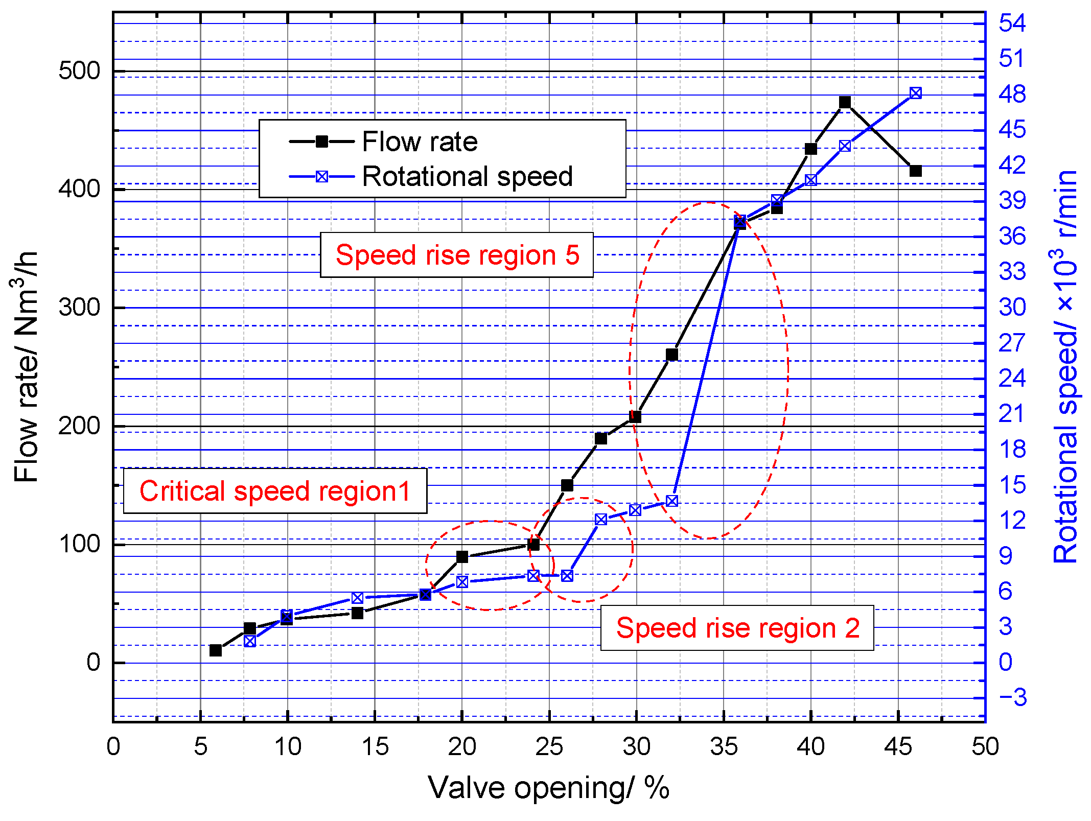
The correspondence between the input flow rate of the driving impeller and the rotational speed is given in Figure 4. The critical speed region 1 in Figure 4 corresponds to region 1 in Figure 3, the speed rise region 2 in Figure 4 corresponds to region 2 in Figure 3, and the speed rise region 5 in Figure 4 corresponds to region 5 in Figure 3. The maximum value of drive flow required for the rotor speed-up process was 473 Nm3/h. After 25% valve-opening, the rate of increase in flow and speed increased, and the relationship between the two will be focused on later.
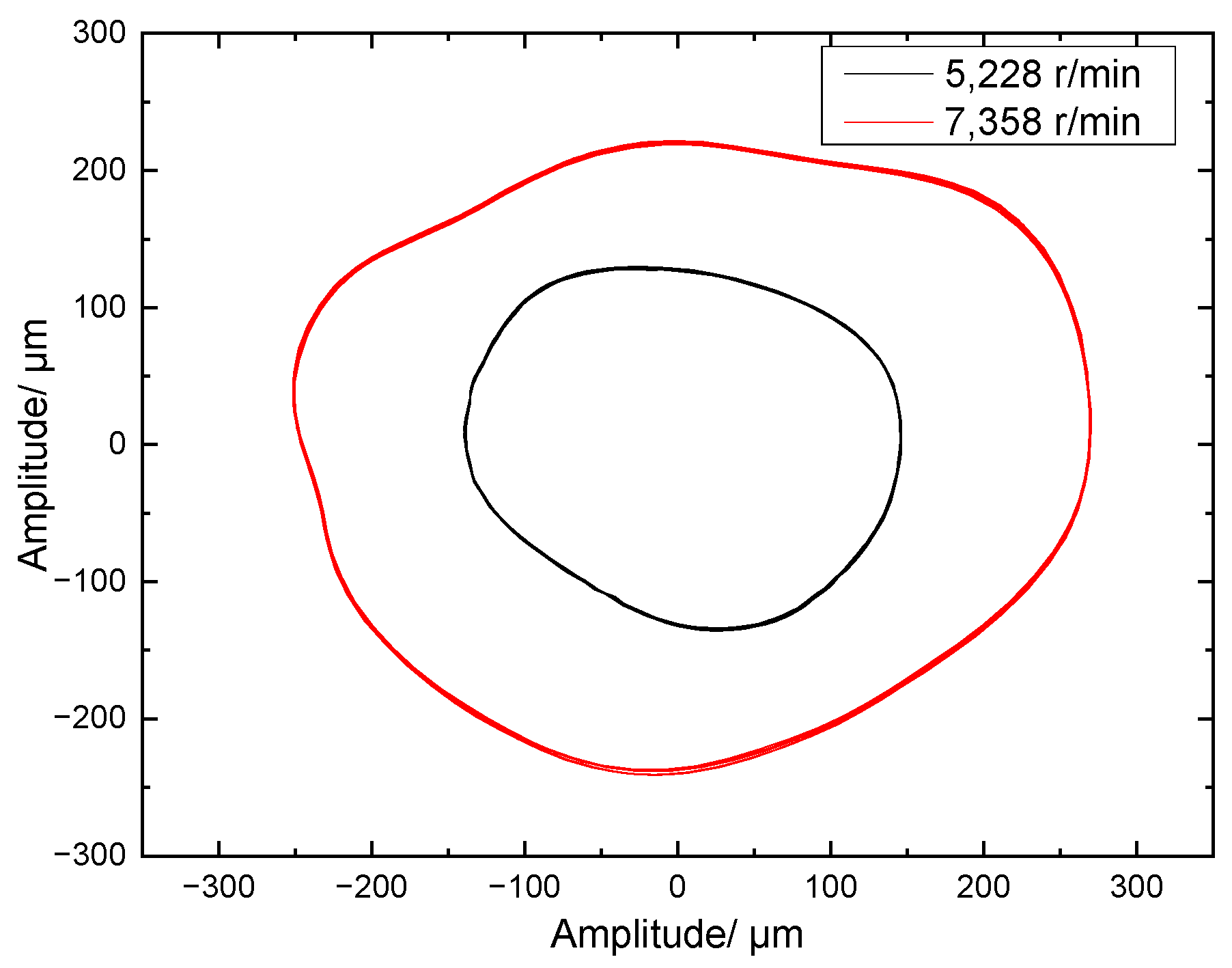
Critical speed region 1. The critical speed region of the multi-disc rotor system supported by gas bearings was from 7300 r/min to 7850 r/min, corresponding to a frequency range of 121.67 Hz to 130.83 Hz. When the rotor passed through the critical speed region, the vibration amplitude appeared at a peak, and the vibration phase appeared to be deflected by about 180°. At the same time, near the critical speed, a second peak occurred, taking the horizontal direction vibration of the turbine end as an example, as shown in Figure 5, the main critical speed peak occurred at 7834 r/min (corresponding to 130.57 Hz), and the sub-critical speed peak occurred at 9214 r/min (corresponding to 153.57 Hz), which may have been due to the anisotropy of the unit support stiffness. The axis orbits of the rotor through the critical speed region are shown in Figure 6. It can be seen that the amplitude of the axis orbits increased significantly as it passed through the approaching critical speed region.
Speed rise region 2 after the critical speed. In the critical-speed region, the turbine flow (input energy) driving the rotor rotation continuously increased, but there was no sudden increase in rotor speed. The input energy went through the “energy storage” pathway to be stored in the critical speed region, which was reflected by higher vibration amplitude. When the stored energy reached a critical point, the energy was released into kinetic energy that drove the rotor to rotate, as shown in region 2 in Figure 3. In this experiment, the lift-off speed point of the multi-disc rotor system supported by gas bearing after the critical speed was 8644 r/min, and the speed range of the lift-off area was 8644–12,260 r/min. In region 2, the rotor speed-up rate was higher, up to 734 r/min/s. The axis orbits and time domain waveforms before and after the lift-off speed are shown in Figure 7 and Figure 8. The vibration amplitude of the rotor in the speed rise region 2 was much lower than that of the rotor in the critical-speed region. In Figure 8, the vibration amplitude in the horizontal direction decreased suddenly at 140.65 s, and accordingly, the vibration amplitude in the vertical direction decreased suddenly at 140.70 s.
Sub-frequency rubbing region 3. The speed range corresponding to this region was 12,260–13,558 r/min. In this region, the rotor had a slight rub-impact phenomenon caused by low frequency, and there were obvious double low-frequency and rub-impact sweep frequency components. As shown in Figure 9, the frequency spectrum characteristics of the double low-frequency were 125 Hz and 161 Hz, respectively. The vibration with a frequency of 125 Hz was a low-frequency vibration coupled with the critical speed. The vibration amplitude corresponding to the low frequency of 125 Hz was 19 μm, and the vibration amplitude corresponding to the low frequency of 161 Hz was 13.5 μm. The axis orbits of this region are shown in Figure 10.
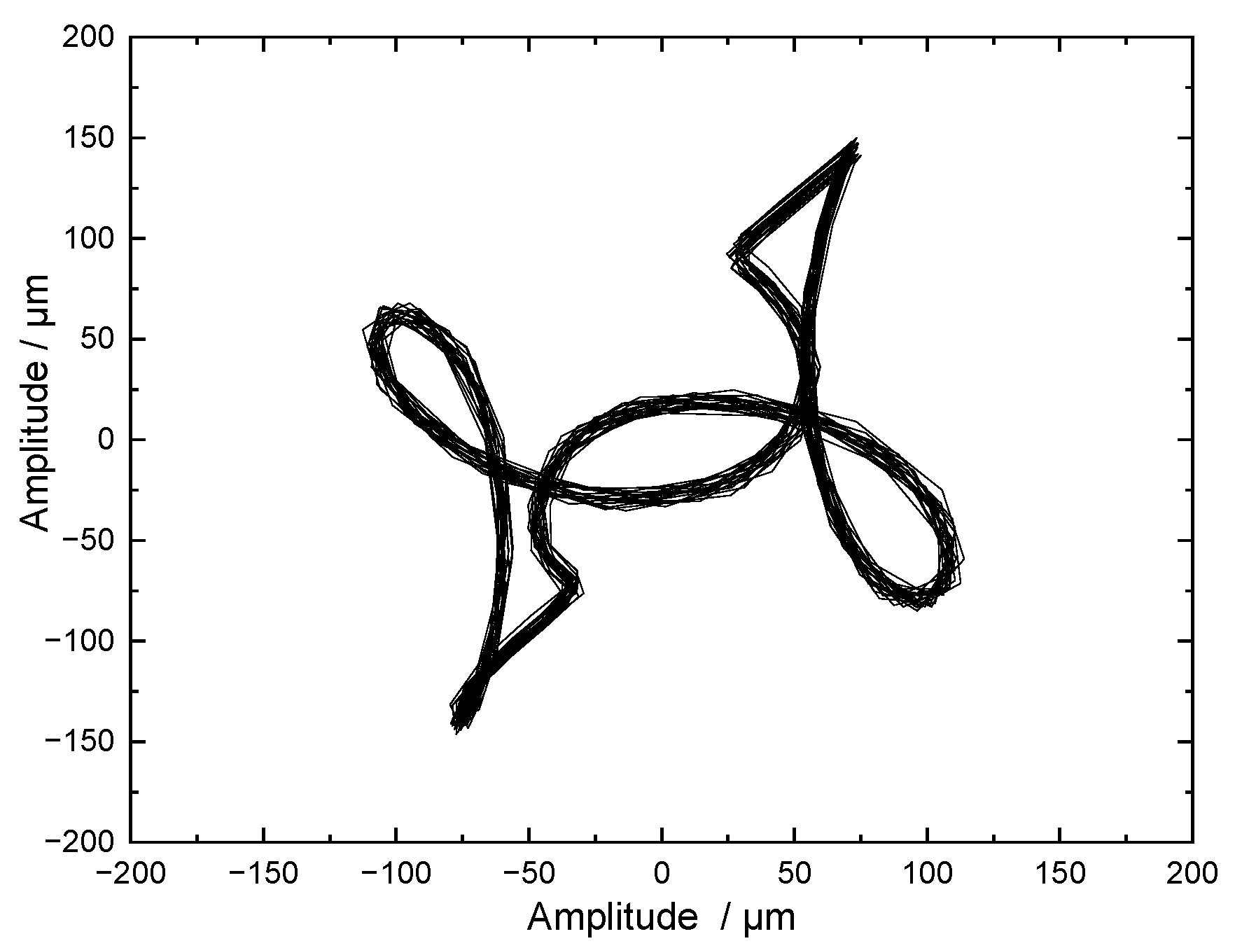
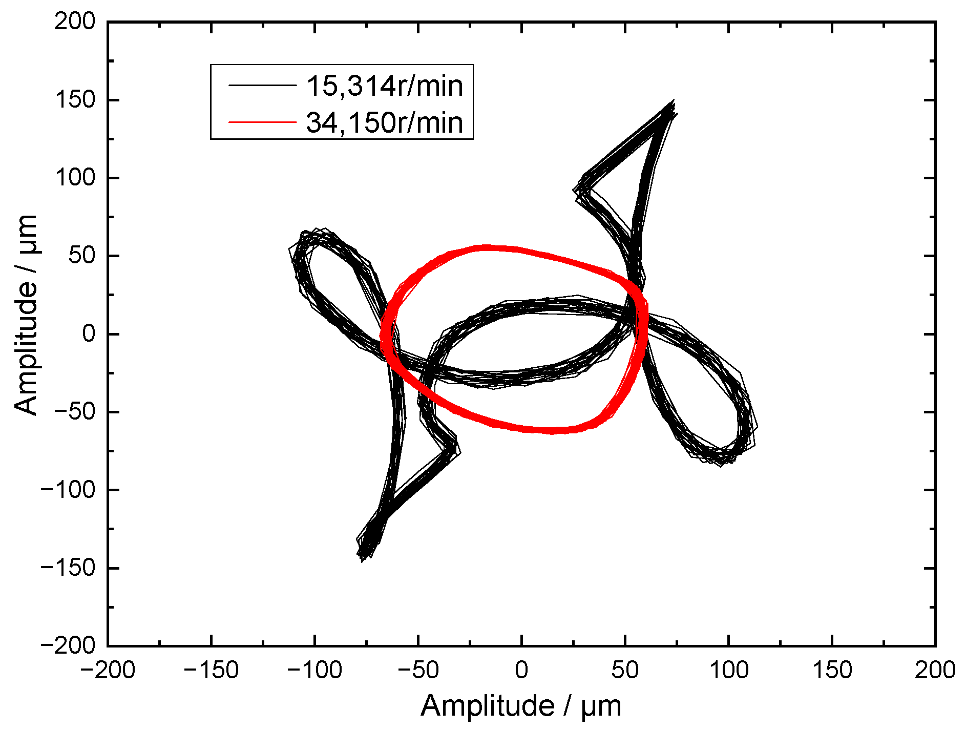
Multiple frequency region 4. The corresponding speed range of this region was 13,558–15,430 r/min. In this region, there were obvious double frequencies and triple frequencies. The axis orbit and spectral characteristics are shown in Figure 11 and Figure 12. In Figure 12, the domain map of the multiple frequency region is shown, and the vibration amplitude of the multiple frequency was smaller than the power frequency (1× frequency), while the amplitude of the triple frequency was smaller than the amplitude of the double frequency.
Speed rise region 5 after the disappearance of the sub/multiple frequency. In the sub-frequency rubbing region 3 and multiple frequency region 4, the turbine flow driving the rotor rotation continuously increased, as marked in Figure 4. The input energy was partly stored in the sub-frequency whirling, and part of the energy was lost through the slight rubbing. When the stored energy reached a critical point, the energy was released into kinetic energy to drive the rotor to rotate, resulting in an increase in speed, as shown in Figure 3 for region 5. The speed range of this region was 15,430–35,190 r/min. The rotor speed-up rate was 1874 r/min/s. The axis orbit in this region is shown in Figure 13. The axis orbit was dominated by cycle one and the vibration amplitude was small.
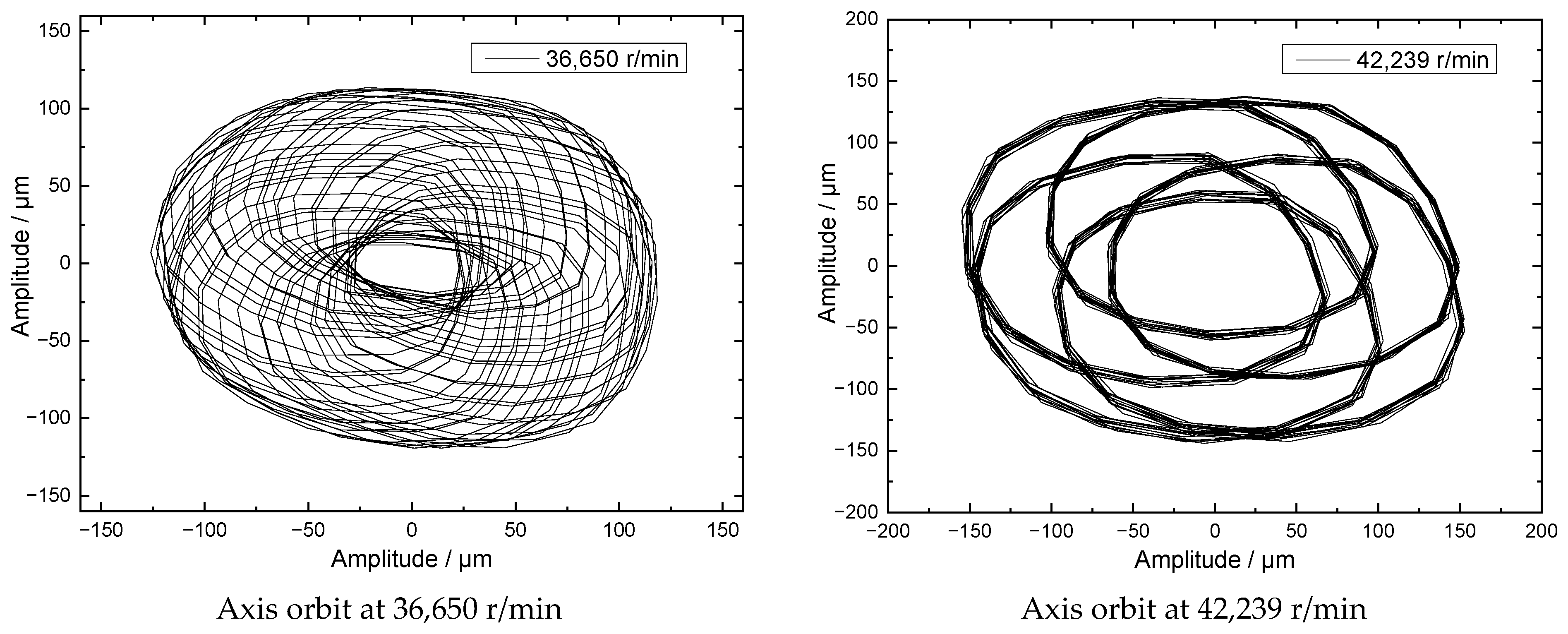
Gas film whipping region 6. The speed range of gas film whipping was 35,190–46,730 r/min. When the rotational speed reached 35,190 r/min, a low-frequency vibration at 132 Hz occurred. As the rotational speed fluctuated, the low frequency was basically unchanged, which was always consistent with the power frequency of the critical speed, showing the characteristics of low-frequency whipping. Its spectral characteristics are shown in Figure 14. The vibration amplitude of low-frequency whipping was 32 μm and remained unchanged. In this region, the rotor axis orbit is shown in Figure 15, which is a typical quasi-periodic motion feature.
Region 7 after gas film whipping. When the speed reached 46,730 r/min, the low-frequency whipping disappeared, and the rotor was running at the power frequency. The amplitude of the power frequency vibration was basically the same as that of the rotor vibration in the low-frequency whipping region, and the axis orbit is shown in Figure 16. Different from the speed rise after the previous low-frequency whirling, the amplitude of the rotor power frequency vibration remained basically unchanged after the low-frequency whipping disappeared, and the speed did not rise. But the speed region failed to be sustained for long (4–5 s), and the rotor lost stability. Therefore, it is generally accepted that prolonged gas film whipping causes dynamic rotor instability.
Speed-down rubbing region 8. When the rotational speed reached 46,875 r/min, the rotor suddenly slowed down. It can be clearly seen that the deceleration rate (25,311 r/min/s) of the deceleration process was very large, and there were obvious low-frequency whirling and rubbing sweep characteristics.
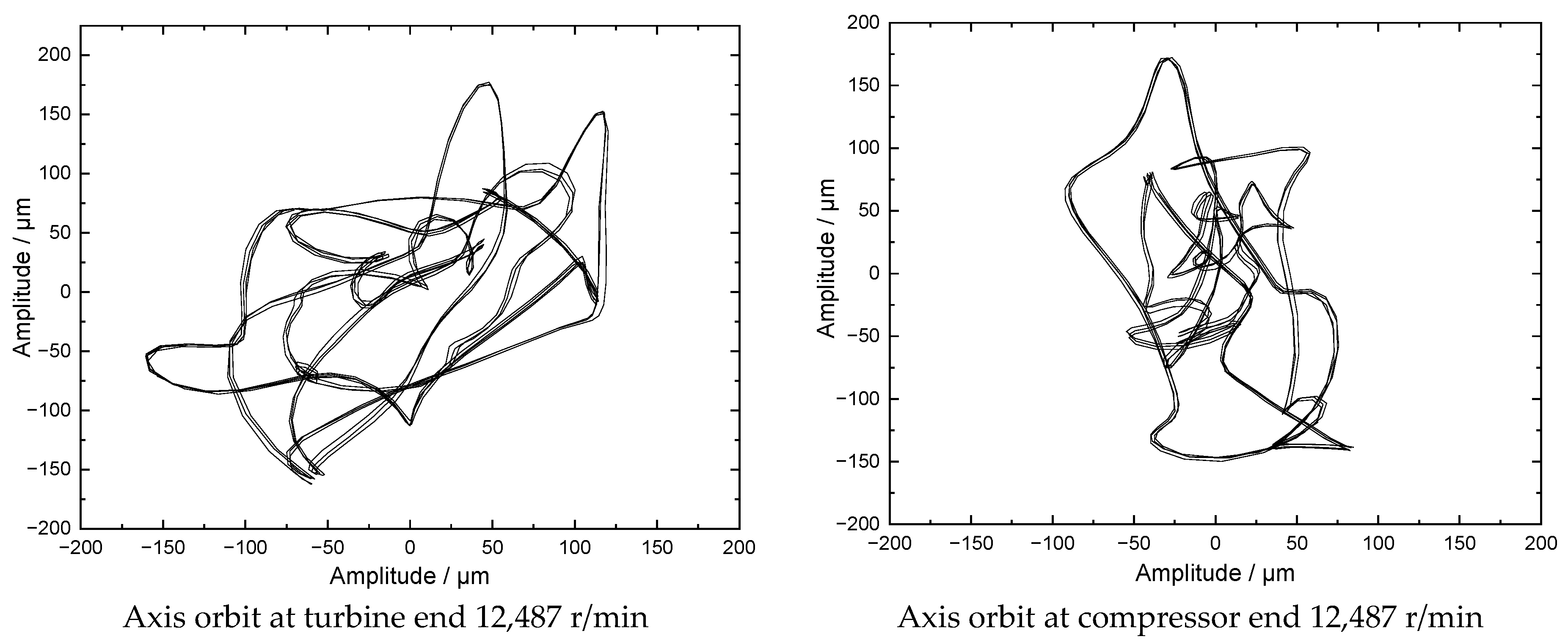
Figure 17 and Figure 18 respectively give the change in the axis orbit of the turbine end and the compressor end during the deceleration process. It can be seen that, when the speed was reduced and at a speed of 47,160 r/min, the low-frequency whirl with a frequency of about 456 Hz appeared at the turbine end, and the whirl ratio was about 0.58. The orbit of the axis showed obvious period-two characteristics during the low-frequency whirl.
At a speed of 43,990 r/min, the shaft axis orbit of the turbine end showed obvious rubbing characteristics, but the shaft axis orbit of the compressor end did not exhibit rubbing, showing chaotic characteristics and obvious eccentric characteristics. With the decrease of the rotational speed, the shaft axis orbit of the turbine end changes from serious rub-impact to exit rub-impact, while the shaft axis orbit of the compressor end has little vibration amplitude. When the rotational speed is 34,760 r/min, the shaft axis orbit suddenly changes from period 1 to the offset state at the compressor end, and accordingly, peak elimination occurs at the turbine end. From the axis orbit at the rotational speed of 34,760 r/min, it can be guessed that the rotor and bearing at the compressor end may be locking up, and the failure characteristics will be further analyzed later by disassembling the machine.
Figure 19 shows the spectrum characteristics at a speed of 43,990 r/min during the deceleration process. It can be seen that, due to the high deceleration rate, the power frequency of the rotor presented frequency band characteristics, low-frequency characteristics with a frequency of 456 Hz, and frequency sweep characteristics of rubbing.
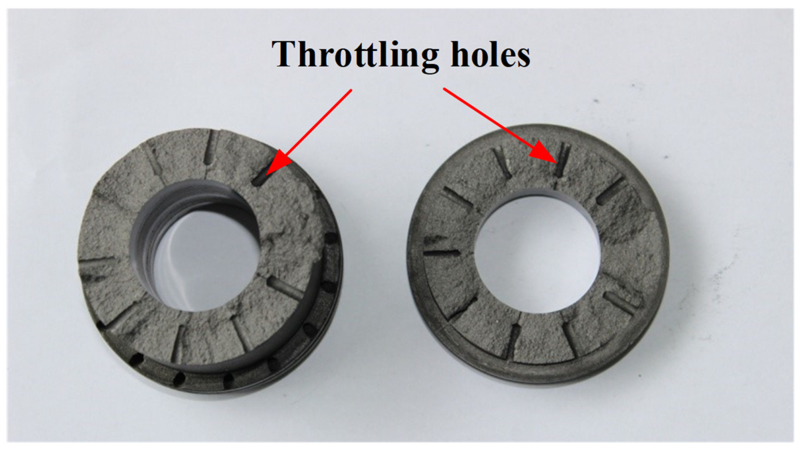
Disassembly inspection. After subsequent disassembly inspection, it was found that the aerostatic bearing at the compressor end was broken, and half of the bearing was attached to the rotor. Combined with the characteristics of the section, as shown in Figure 20, it can be inferred that the bearing was twisted and broken, which is consistent with the characteristics of the axis orbit of the compressor end at the speed of 34,760 r/min in Figure 18. The fracture of the surface of the bearing was along the supply hole cross-section.
It was also found that there were many cracks at the edge of the resin and the magnetic block on the disc at the turbine end. As shown in Figure 21, the disc deformed outward along the radius direction, and the deformation was more than 1 cm. This directly affected the dynamic balance of the rotor, which in turn led to a sharp deceleration of the rotor at 47,600 r/min. The main reason for cracking was that the outward centrifugal force generated by the magnet block under high-speed rotation deformed the wheel disc. The low frequency vibration and critical speed vibration aggravated the deformation characteristics.
4.2. Experimental Results of No. 2
Figure 22 shows the bifurcation diagram of the speed-up process of experiment 2. It can be seen that the critical speed of the shafting in experiment 2 was 8238 r/min, which was higher than the critical speed of 7834 r/min in experiment 1. The main reason is that the increase in bearing gas supply pressure improved the bearing gas film stiffness. When the speed was 41,825 r/min (corresponding frequency was 697 Hz), chaotic characteristics appeared on the bifurcation diagram. The frequency spectrum characteristics at this speed are shown in Figure 23. A low frequency of 154 Hz appeared. The low-frequency value was higher than the frequency value corresponding to the critical speed of the rotor (137.3 Hz), which could be judged as the characteristics of gas film whipping, but the vibration amplitude of the low frequency was very small.
Figure 24 shows the axis orbits of the rotor during the acceleration process. Before the speed of 41,825 r/min, the axis orbit presented a period-one characteristic. After the gas film whipping occurred, the axis orbit exhibited quasi-periodic characteristics. The amplitude of the axis orbit at the critical speed of 8238 r/min was smaller than the amplitude of the axis orbit at the critical speed in experiment 1, which was due to the damping effect of the rubber damping pad.
The following conclusions can be drawn from the comparative experiment. The increase in bearing supply pressure and the introduction of a rubber damping pad eliminated the low-frequency vibration in the process of rotor acceleration.
5. Conclusions
In this study, the dynamic characteristics of the multi-disc rotor system supported by aerostatic bearing were studied on a test bench. The main conclusions are as follows.
The test showed the dynamic characteristics of critical energy storage and whirling energy storage. During the energy storage period, the vibration amplitude of the rotor was large, and the rotor speed was basically unchanged with the increase in input energy. However, when the increase in speed occurred, the vibration amplitude of the rotor decreased obviously, and the rate of increase was large. The energy storage phenomenon can be fully utilized during the operation of the rotor to store the input energy, but the release process should be properly controlled to prevent the rotor instability caused by the larger rate of increase.
The test showed the dynamic characteristics of gas film whipping and the axis orbit presents quasi-periodic characteristics, and the bifurcation diagram presented chaotic characteristics with boundaries. When the gas film whipping occurred, the vibration amplitude of the rotor was large, and could easily cause other instabilities. In the experiment on a multi-disc rotor system supported by aerostatic bearing in this paper, the gas film whipping caused the deformation of the disc, which led to an increase in imbalance, the rubbing fault of the rotor, and the fracture of the bearing.
The increase in bearing supply pressure and the introduction of the rubber damping pad eliminated the low-frequency vibration in the acceleration process to improve the stability of the shafting.
The experimental results presented in this paper can provide experimental support for the analysis and diagnosis of similar structures and faults, which has important practical significance.
Author Contributions
Conceptualization, Z.S. and D.H.; Methodology, J.Z.; Data curation, Y.C.; Formal analysis, Z.S. and D.H.; Investigation, Z.S. and J.Z.; Project administration, D.H.; Software, Y.C.; Validation, Z.S. and J.Z.; Writing—original draft, Z.S. and D.H.; Writing—review and editing, Z.S. and D.H.; Funding acquisition, D.H. All authors have read and agreed to the published version of the manuscript.
Funding
This work was supported by the Youth Innovation Promotion Association CAS (2021141) and the National Natural Science Foundation of China (Grant No. 11602268).
Data Availability Statement
The original contributions presented in the study are included in the article, further inquiries can be directed to the corresponding author.
Acknowledgments
The authors must thank Jinfu Yang (from the Institute of Engineering Thermophysics, Chinese Academy of Sciences) for his guidance on the experimental designs.
Conflicts of Interest
The authors declared no conflicts of interest with respect to the research, authorship, and publication of this article.
References
- Gao, Q.; Chen, W.; Lu, L.; Huo, D.; Cheng, K. Aerostatic bearings design and analysis with the application to precision engineering: State of the art and future perspectives. Tribol. Int. 2019, 135, 1–17. [Google Scholar] [CrossRef]
- Shinnoh, Y.H. Design concept and structural configuration of advanced nano-pattren generator with large work area “Angel”. Int. J. Autom. 2011, 5, 38–44. [Google Scholar]
- Xu, F.; Dong, Z.; Zhang, H.; Xie, Z. Vibration characteristics control of hybrid radial gas foil bearing-rotor system: Simulation and experiment. Mech. Syst. Signal Process. 2023, 198, 110402. [Google Scholar] [CrossRef]
- Wang, P.; Chen, B.; Li, J.; Wang, J.; Zhang, Y.; Feng, K. Novel aerostatic bearings with hermetically squeeze film dampers for the improvement of stability: Theoretical and experimental investigations. Precis. Eng. 2024, 85, 263–278. [Google Scholar] [CrossRef]
- Wang, G.; Li, W.; Liu, G.; Feng, K. A novel optimization design method for obtaining high-performance micro-hole aerostatic bearings with experimental validation. Tribol. Int. 2023, 185, 108542. [Google Scholar] [CrossRef]
- Wang, P.; Zhang, Y.; Feng, L.; Hou, W.; Wang, J.; Li, W.; Feng, K. Study on the pneumatic hammer phenomenon of aerostatic bearings based on the empirical mode method: Numerical and experimental analysis. Tribol. Int. 2023, 181, 108305. [Google Scholar] [CrossRef]
- Feng, K.; Li, J.; Li, W.; Huang, J.; Gao, F.; Sun, J. A novel parallel capillary-cavity model for the analysis of pneumatic hammer vibration in porous aerostatic bearings. Tribol. Int. 2023, 189, 108993. [Google Scholar] [CrossRef]
- Gao, Q.; Qi, L.; Gao, S.; Lu, L.; Song, L.; Zhang, F. A FEM based modeling method for analyzing the static performance of aerostatic thrust bearings considering the fluid-structure interaction. Tribol. Int. 2021, 156, 106849. [Google Scholar] [CrossRef]
- Yu, P.; Huang, L.; Li, S.; Guo, L.; Zhong, M.; Zhang, L. Theoretical predictions and experimental measurements of novel aerostatic bearing with multi-inclined-orifice restrictors for the improvement of stability. Precis. Eng. 2024, 88, 266–278. [Google Scholar] [CrossRef]
- Wu, Y.; Li, C.; Li, J.; Du, J. Lubrication mechanism and characteristics of aerostatic bearing with close-spaced micro holes. Tribol. Int. 2024, 192, 109278. [Google Scholar] [CrossRef]
- Maamari, N.; Krebs, A.; Weikert, S.; Wild, H.; Wegener, K. Stability and dynamics of an orifice based aerostatic bearing with a compliant back plate. Tribol. Int. 2019, 138, 279–296. [Google Scholar] [CrossRef]
- An, L.; Wang, W.; Wang, C. Dynamic modeling and analysis of high-speed aerostatic journal bearing-rotor system with recess. Tribol. Int. 2023, 187, 108686. [Google Scholar] [CrossRef]
- Yang, P.; Zhu, K.; Wang, X. On the non-linear stability of self-acting gas journal bearings. Tribol. Int. 2009, 42, 71–76. [Google Scholar] [CrossRef]
- Zhang, J.; Zou, D.; Ta, N.; Rao, Z. Numerical research of pressure depression in aerostatic thrust bearing with inherent orifice. Tribol. Int. 2018, 123, 385–396. [Google Scholar] [CrossRef]
- Zhang, J.; Zou, D.; Ta, N.; Rao, Z.; Ding, B. A numerical method for solution of the discharge coefficients in externally pressurized gas bearings with inherent orifice restrictors. Tribol. Int. 2018, 125, 156–168. [Google Scholar] [CrossRef]
- Zhang, J.; Yu, F.; Zou, D.; Ta, N.; Rao, Z. Comparison of the characteristics of aerostatic journal bearings considering misalignment under pure-static and hybrid condition. Proc. Inst. Mech. Eng. Part J J. Eng. Tribol. 2019, 233, 769–781. [Google Scholar] [CrossRef]
- Shi, J.; Cao, H.; Jin, X. Dynamics of 5-DOF aerostatic spindle with time-varying coefficients of air bearing. Mech. Syst. Signal Process. 2022, 172, 109005. [Google Scholar] [CrossRef]
- Shi, J.; Jin, X.; Cao, H. Chatter stability analysis in Micro-milling with aerostatic spindle considering speed effect. Mech. Syst. Signal Process. 2022, 169, 108620. [Google Scholar] [CrossRef]
- Shi, J.; Cao, H.; Jian, X. Investigation on the static and dynamic characteristics of 3-DOF aerostatic thrust bearings with orifice restrictor. Tribol. Int. 2019, 138, 435–449. [Google Scholar] [CrossRef]
- Chen, C.; Yang, J.; Nie, C. Experimental research on nonlinear dynamic characteristic of gas lubrication bearings and high speed rotors. J. Aerosp. Power 2008, 23, 1413–1419. [Google Scholar]
- Bian, S.; Wang, Z.; Yang, J.; Yu, M.; Bian, J. Experiment on axial clearance on high-speed dual-turbine rotor stability. J. Aerosp. Power 2017, 32, 1091–1098. [Google Scholar]
- Yang, J.; Chen, C.; Liu, Y.; Han, D. An engineering stability criterion and its experimental validation of frequency couple modulation for sliding rotor-bearing system. J. Vib. Shock 2010, 29, 97–104. [Google Scholar]
- Chen, Y.; Liu, Y.; Yang, W.; Wang, Y.; Zhang, L.; Wu, Y. Research on optimization and verification of the number of stator blades of kW ammonia working medium radial flow turbine in ocean thermal energy conversion. J. Mar. Sci. Eng. 2021, 9, 901. [Google Scholar] [CrossRef]
- Bischoff, S.; Decker, L. First operating results of a dynamic gas bearing turbine in an industrial hydrogen liquefier. AIP Conf. Proc. 2010, 1218, 887. [Google Scholar]
- Ohlig, K.; Bischoff, S. Dynamic gas bearing turbine technology in hydrogen plants. In Advances in Cryogenic Engineering. Transactions of the Cryogenic Engineering Conference—CEC; American Institute of Physics AIP: College Park, MD, USA, 2012; Volume 57. [Google Scholar]
- Shi, T.; Xiong, W.; Peng, X.; Feng, J.; Guo, Y. Experimental investigation on the start-stop performance of gas foil bearing-rotor system in the centrifugal air compressor for hydrogen fuel cell vehicles. Int. J. Hydrogen Energy 2023, 48, 34501–34519. [Google Scholar] [CrossRef]
- Shi, T.; Wang, H.; Yang, W.; Peng, X. Mathematical modeling and optimization of gas foil bearings-rotor system in hydrogen fuel cell vehicles. Energy 2024, 290, 130129. [Google Scholar] [CrossRef]
- Stoop, F.; Meier, S.; Civelli, P.; Mayr, J.; Wegener, K. Multi-variable rotor dynamics optimization of an aerostatic spindle. CIRP J. Manuf. Sci. Technol. 2023, 42, 12–23. [Google Scholar] [CrossRef]
- Belforte, G.; Colombo, F.; Raparelli, T.; Trivella, A.; Viktorov, V. High-speed electrospindle running on air bearing: Design and experimental verification. Meccanica 2008, 43, 591–600. [Google Scholar] [CrossRef]
- Han, D.; Tang, C.; Hao, L.; Yang, J. Experimental studies on the effects of bearing supply gas pressure on the response of a permanent magnet disk-type motor rotor. J. Mech. Sci. Technol. 2016, 30, 4887–4892. [Google Scholar] [CrossRef]
Figure 1.
Multi-disc rotor structure supported by aerostatic bearings.

Figure 2.
Experimental bench body of multi-disc rotor system supported by aerostatic bearings.

Figure 3.
Time–frequency–amplitude three-dimensional spectrum of multi-disc rotor speed–up and –down process.
Figure 3.
Time–frequency–amplitude three-dimensional spectrum of multi-disc rotor speed–up and –down process.

Figure 4.
Corresponding curve of valve flow-opening and rotational speed in the process of rotor speed−up.
Figure 4.
Corresponding curve of valve flow-opening and rotational speed in the process of rotor speed−up.

Figure 5.
Vibration response curve of rotor speed-up process.

Figure 6.
Comparative analysis of axis orbits before and after critical speed at turbine end (5228 r/min vs. 7358 r/min).
Figure 6.
Comparative analysis of axis orbits before and after critical speed at turbine end (5228 r/min vs. 7358 r/min).

Figure 7.
Characteristics of rotor axis orbits before and after lift-off speed (before lift-off speed 8048 r/min, after lift-off speed 10,328 r/min).
Figure 7.
Characteristics of rotor axis orbits before and after lift-off speed (before lift-off speed 8048 r/min, after lift-off speed 10,328 r/min).

Figure 8.
Time-domain waveforms before and after the lift-off speed (140.4–140.8 s).

Figure 9.
Spectral characteristics at rotational speed of 12,295 r/min.

Figure 10.
Axis orbits in region 3.

Figure 11.
Axis orbit at turbine end at 15,314 r/min.

Figure 12.
Spectral characteristics at 15,314 r/min.

Figure 13.
Axis orbit before and after lift-off speed.

Figure 14.
Spectrum and time-domain waveform in the gas film whipping region.

Figure 15.
Axis orbits of the gas film whipping region.

Figure 16.
Axis orbits before and after the low-frequency whipping.

Figure 17.
Axis orbits in the region of the turbine-end downslope contact.

Figure 18.
Axis orbits in the region of reduced speed rubbing at the compressor end.

Figure 19.
Spectrum characteristics at 43,990 r/min.

Figure 20.
Bearing fracture failure at the compressor end.

Figure 21.
Disc status after machine dismantling at turbine end.

Figure 22.
Bifurcation diagram of experimental scheme 2.

Figure 23.
Spectrum characteristics at 41,825 r/min.

Figure 24.
Axis orbit during the acceleration process of experimental scheme 2.


Table 1.
Main structural parameters of rotor and bearings.
| Parameters | Value | Unit |
|---|---|---|
| Shaft mass | 896.0 | g |
| Disc mass | 310.0 | g |
| Turbine mass | 169.0 | g |
| Compressor mass | 136.0 | g |
| Total rotor mass | 2602.0 | g |
| Bearing span | 112.7 | mm |
| Medial disc span | 169.0 | mm |
| Outer disc span | 195.3 | mm |
| Number of magnets | 8 | / |
| Impeller mass center distance | 249.80 | mm |
| Bearing inner diameter | 25.0 | mm |
| Bearing length | 40.0 | mm |
| Number of throttle rows | 2 | / |
| Number of throttling holes per row | 10 | / |
| Throttle hole diameter | 0.30 | mm |
| O-ring diameter | 3.10 | mm |
Table 2.
Experimental schemes under different bearing supply pressures.
| Experimental Scheme | Bearing Supply Pressure/MPa | |
|---|---|---|
| Aerostatic Bearing at Compressor End (Set Value/Actual Value) | Aerostatic Bearing at Turbine End (Set Value/Actual Value) | |
| No. 1 | 0.60 MPa/0.61 MPa | 0.60 MPa/0.60 MPa |
| No. 2 | 0.75 MPa/0.76 MPa | 0.75 MPa/0.76 MPa |
Disclaimer/Publisher’s Note: The statements, opinions and data contained in all publications are solely those of the individual author(s) and contributor(s) and not of MDPI and/or the editor(s). MDPI and/or the editor(s) disclaim responsibility for any injury to people or property resulting from any ideas, methods, instructions or products referred to in the content. |
© 2024 by the authors. Licensee MDPI, Basel, Switzerland. This article is an open access article distributed under the terms and conditions of the Creative Commons Attribution (CC BY) license (https://creativecommons.org/licenses/by/4.0/).
Share and Cite
MDPI and ACS Style
Su, Z.; Zhang, J.; Cai, Y.; Han, D. Experimental Research on Dynamic Characteristics of a Multi-Disc Rotor System Supported by Aerostatic Bearings. Lubricants 2024, 12, 151. https://doi.org/10.3390/lubricants12050151
AMA Style
Su Z, Zhang J, Cai Y, Han D. Experimental Research on Dynamic Characteristics of a Multi-Disc Rotor System Supported by Aerostatic Bearings. Lubricants. 2024; 12(5):151. https://doi.org/10.3390/lubricants12050151
Chicago/Turabian StyleSu, Zhimin, Jianbo Zhang, Yimou Cai, and Dongjiang Han. 2024. "Experimental Research on Dynamic Characteristics of a Multi-Disc Rotor System Supported by Aerostatic Bearings" Lubricants 12, no. 5: 151. https://doi.org/10.3390/lubricants12050151
Note that from the first issue of 2016, this journal uses article numbers instead of page numbers. See further details here.