
Fluid Flow to Electricity: Capturing Flow-Induced Vibrations with Micro-Electromechanical-System-Based Piezoelectric Energy Harvester

1
Department of Mechanical Engineering, Seoul National University of Science and Technology, Seoul 01811, Republic of Korea
2
Department of Mechanical and Aerospace, University at Buffalo, The State University of New York, Buffalo, NY 14260, USA
3
Department of Mechanical and Automotive Engineering, Seoul National University of Science and Technology, Seoul 01811, Republic of Korea
*
Author to whom correspondence should be addressed.
Micromachines 2024, 15(5), 581; https://doi.org/10.3390/mi15050581
Submission received: 2 April 2024
/
Revised: 23 April 2024
/
Accepted: 26 April 2024
/
Published: 27 April 2024
(This article belongs to the Special Issue MEMS Nano/Microfabrication)
Abstract
:We introduce a micro-electromechanical system (MEMS) energy harvester, designed for capturing flow energy. Moving beyond traditional vibration-based energy harvesting, our approach incorporates a cylindrical oscillator mounted on an MEMS chip, effectively harnessing wind energy through flow-induced vibration (FIV). A highlight of our research is the development of a comprehensive fabrication process, utilizing a 5.00 µm thick cantilever beam and piezoelectric film, optimized through advanced micromachining techniques. This process ensures the harvester’s alignment with theoretical predictions and enhances its operational efficiency. Our wind tunnel experiments confirmed the harvester’s capability to generate a notable electrical output, with a peak voltage of 2.56 mV at an 8.00 m/s wind speed. Furthermore, we observed a strong correlation between the experimentally measured voltage frequencies and the lift force frequency observed by CFD analysis, with dominant frequencies identified in the range of 830 Hz to 867 Hz, demonstrating the potential application in actual flow environments. By demonstrating the feasibility of efficient energy conversion from ambient wind, our research contributes to the development of sustainable energy solutions and low-power wireless electron devices.
1. Introduction
In today’s rapidly advancing technological landscape, the need for compact and efficient power sources has become increasingly critical [1,2,3]. This need is paramount not only in traditional arenas such as wireless sensor networks and wearable devices but also in rapidly growing fields like advanced mobility solutions and drone technology. These dynamic applications, characterized by their demand for autonomy and enduring power sustainability, are transforming our interconnected and mobile world. Specifically, the inherent movement of devices in sectors like drone technology and new mobility solutions introduces novel opportunities for energy harvesting [4,5,6]. This interaction with airflow represents an overlooked method to boost their sustainability and operational efficiency.
In this context, the development of micro-electromechanical system (MEMS)-based energy harvesters, which are capable of transforming kinetic energy from environmental forces like wind into electrical power, signifies a critical breakthrough [7,8]. Harvesters employing cantilever beams equipped with piezoelectric films excel in harnessing kinetic energy from diverse sources, including vibration, gravitational forces, and wind [9,10,11,12,13]. Additionally, the piezoelectric energy harvesting method, compared to electromagnetic and triboelectric energy harvesting methods, has the advantage of easier miniaturization through MEMS processes and is less affected by external conditions such as dust and humidity [14,15]. The materials commonly chosen for piezoelectric films include PZT and AlN. PZT, known for its high piezoelectric properties, has been applied in MEMS energy harvesters, typically harvesting energy ranging from 1 μW to 100 μW [16,17,18]. However, a significant drawback of PZT is that its use in micromachining processes can contaminate fabrication equipment. On the other hand, MEMS harvesters that employ AlN, while having lower piezoelectric properties compared to PZT, are noted for their ease of processing in MEMS fabrication. The energy harvesting capacity of AlN-based MEMS energy harvesters ranges from 0.8 nW to 10 μW [19,20]. However, the low power levels generated by energy harvesters pose challenges in electrical circuit operations such as rectification. Nonetheless, several studies have been conducted to rectify and boost power at the mV and nW-μW levels into usable scales for energy harvesting [21,22].
Demonstrating a substantial energy density of approximately 0.3 μW/mm3, these devices are suitable for a broad spectrum of applications [10,23]. Conventional vibration energy harvesters, typically comprising a silicon cantilever beam with a piezoelectric film and a proof mass (Figure 1a), are noted for their manufacturing simplicity [23,24]. However, their efficiency predominantly relies on matching the external excitation frequency with their resonant frequency. To overcome the limitation of narrow operational bandwidths that is inherent in resonant systems, recent research efforts have been directed towards tweaking system parameters such as rigidity, operating frequency, and damping, thereby widening the bandwidth to adapt to varying environmental vibrations [25,26,27].
In this paper, we investigate wind energy harvesting via fluid-induced vibrations (FIVs), which are often used in macro-scale energy harvesting (Figure 1b). Our device consists of an MEMS-based silicon cantilever beam integrated with a piezoelectric film and a cylindrical oscillator that is designed to trigger vibrations effectively in response to wind flow, harnessing energy across diverse environmental settings (Figure 1c). This approach, minimally reliant on external vibration sources, harnesses Karman vortex dynamics to generate perpendicular vibrations to the direction of the fluid flow, thereby facilitating efficient energy capture [23,24,25]. Particularly suited for MEMS applications, this method offers both simplicity and adaptability under varying wind conditions [28,29,30,31,32]. Then, through 2D computational fluid dynamics (CFD) analysis and wind tunnel experiments, we characterize the harvester’s energy harvesting proficiency to evaluate its practical applicability.
This paper is organized as follows: Section 2 describes the structure and operating principles of the MEMS energy harvester, along with the methods and setups for numerical analysis and experiments. Section 3 investigates the behavioral characteristics of the MEMS energy harvester in wind environments through numerical analysis and explores the fabrication and properties of the harvester, demonstrating that actual electricity production aligns with the predicted characteristics through experimental validation. Finally, Section 4 discusses the conclusions of our research, future works, and areas for improvement.
2. Materials and Methods
In this section, we detail the design and fabrication of our MEMS energy harvester, numerical methods for quantifying the fluid forces, and experimental evaluation of the energy harvesting efficiency.
2.1. Design and Principle of MEMS Energy Harvester
Our study introduces a novel MEMS energy harvester, adapted for fluidic environments, representing a significant shift from traditional vibration-based energy harvesters. The key design consideration is the substitution of the conventional proof mass, typically attached to a silicon cantilever beam, with a more responsive cylindrical oscillator made of polylactic acid (PLA). The MEMS energy harvester, with dimensions of approximately 550 mm in width (w) and length (l) and 550 µm in height (h), features a cylindrical oscillator of 2.00 mm in diameter and 10.0 mm in height. Advanced micromachining techniques facilitate the integration of a piezoelectric film composed of aluminum nitride onto the cantilever beam, which is adept at converting vibrational energy to electrical power. The voltage generated by the piezoelectric film is connected to an electrical circuit through aluminum electrodes linked to a 10 MΩ resistor to harvest power. The oscillator plays a crucial role in transducing external fluidic forces into the mechanical motion of the cantilever beam, thereby enhancing electrical energy generation.
Our energy harvester converts vibrational energy from the cantilever beam into electrical power via piezoelectric films. Upon application of external force, the cantilever beam undergoes alternating tensile and compressive stresses in the piezoelectric film, resulting in the generation of an oscillating electric potential. This generated voltage further influences the displacement of the piezoelectric film, forming a coupled mechanical–electrical system of equations. Notably, the finely tuned oscillator’s alignment with the flow conditions ensures continuous generation of Karman vortices, leading to the repetitive motion of the cantilever. This dynamic is encapsulated by Equations (1) and (2), highlighting the intricate interplay between the mechanical and electrical aspects of the harvester [33]:
where the overdot denotes differentiation with respect to time. The parameters m, c, k, Θ, V, FL, Cp, and R represent the effective mass, damping coefficient, stiffness, electromechanical coupling coefficient, voltage, lift force, system capacitance, and electrical resistance, respectively. The electromechanical coupling coefficient represents the conversion efficiency between displacement and voltage. The lift force FL, generated by the Karman vortices around the oscillator is given by , where , , and are the lift coefficient, density of the fluid (air in this study), and flow velocity, respectively. Here, the flow around the oscillator undergoes changes due to the formation of Karman vortices, and it is these vortices that primarily influence the variations in [34,35]. This force initiates vibration of the oscillator, which in turn stimulates the cantilever beam’s motion, driving the energy harvesting process. From Equations (1) and (2), we can anticipate that has a significant impact on the oscillations of the cantilever beam (y) and the voltage (V) generated by the piezoelectric film. This underscores the importance of investigating the variations in due to the formation of Karman vortices when designing energy harvesters. We will explore the effect of around the oscillator through CFD analysis, followed by an experimental assessment of the voltage generated by the MEMS harvester.
2.2. Numerical Analysis of Fluid-Induced Forces on the MEMS Harvester
To accurately capture the fluid dynamics affecting our MEMS energy harvester, a computational analysis was performed, focusing on the influence of the Karman vortex on the oscillator. This detailed analysis is essential for refining the harvester’s design, particularly for optimizing its response to Karman vortex forces. Building upon previous research in fluid-induced vibration (FIV) [31,36], our study emphasizes the importance of lift force variations on the oscillator.
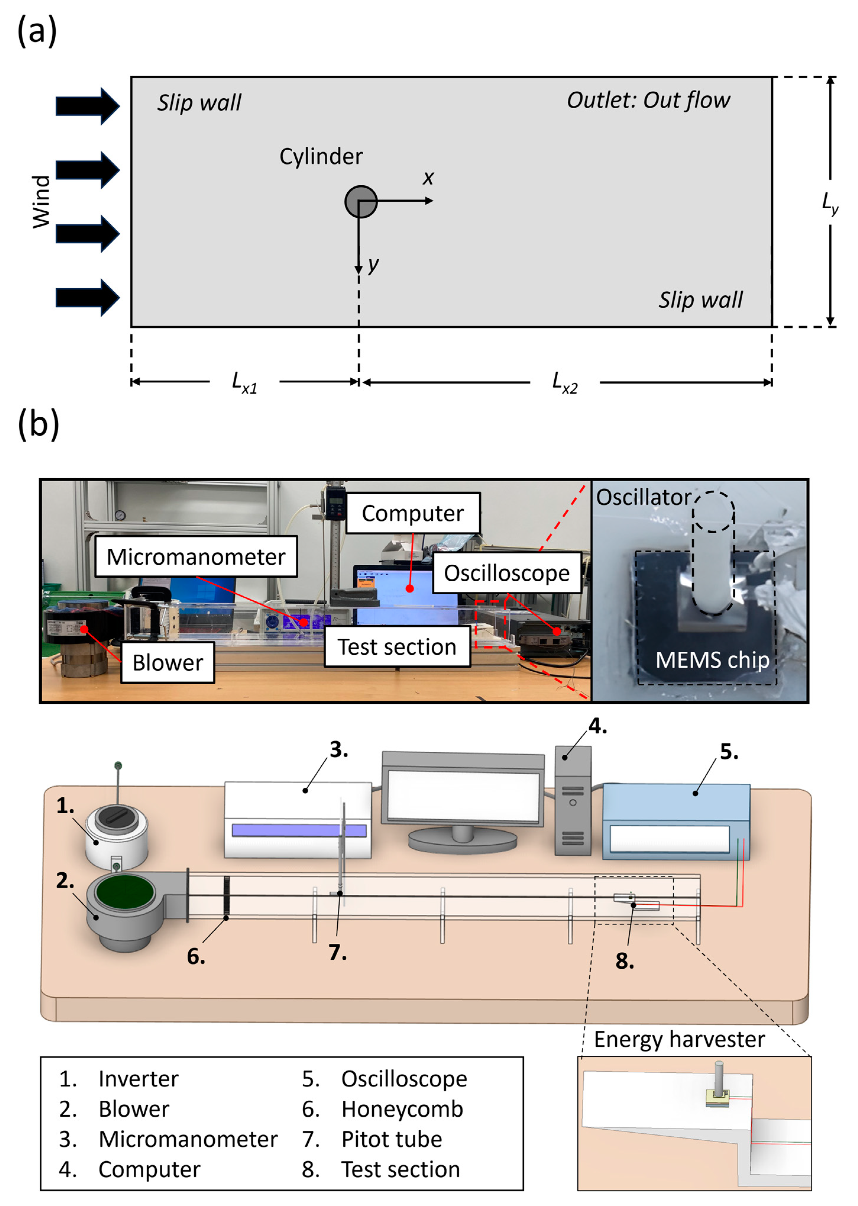
The analysis domain was set similarly to emulate the phenomena observed in experiments. As illustrated in Figure 2a, the domain features a cylinder with a diameter (D) of 2.00 mm, identical to the oscillator of the energy harvester. The surrounding fluid flow field was defined by characteristic lengths Lx1, Lx2, and Ly of 50D, 150D, and 100D, respectively, chosen to minimize the influence of the lateral boundary conditions. For our numerical model, the foundation was set in two key governing equations: the mass conservation (continuity) equation and the momentum conservation equation. These equations offer crucial insights into the fluid behavior around the harvester. The mass conservation equation is given by
where ρ, t, and are the air density, time, and velocity vector, respectively. This equation ensures that the mass is conserved in the flow field around the harvester. The momentum conservation equation is expressed as follows:
where , μ, , and I are the pressure gradient, dynamic viscosity, transpose vector of velocity, and unit tensor, respectively. The boundary conditions for the CFD analysis were carefully chosen to reflect realistic physical interactions under the same conditions as the experiments. At the inlet, a uniform velocity condition was applied, while at the outlet, an outflow condition was set to simulate the fluid exiting the domain. The side surfaces were treated with symmetrical boundary conditions to mimic an infinite fluidic domain, thereby optimizing the computational efficiency and mirroring real-world conditions. The properties of the working fluid in the analysis were set to match the experimental environment, using air properties at atmospheric pressure and a standard temperature of 25.0 °C.
Using the commercial software ANSYS Fluent 2023 R1, we employed a discretization approach based on the finite volume method (FVM) to transform these continuous equations into a computationally manageable format. Second-order discretization schemes for velocity, pressure, and time variables were applied, ensuring higher accuracy. The SIMPLE algorithm was used for pressure–velocity coupling under laminar flow conditions (Re = 1095). A grid independence test was conducted to confirm that the chosen triangular mesh size accurately represented the fluid dynamics. The final mesh configuration consisted of approximately 58,000 nodes, providing a reliable balance between accuracy and computational efficiency. The time step was set to 2.00 10−6 s, selected through sensitivity analysis to fully capture the transient nature of the flow.
2.3. Experimental Setup for Evaluating Performance of MEMS Energy Harvester
Following our observations of the external forces applied to the oscillator through CFD analysis, we aimed to measure the voltage generated by the forces acting on the oscillator through experiments. To evaluate the efficiency of the MEMS-based energy harvester in capturing wind energy under controlled conditions, we designed a series of wind tunnel experiments.
The experimental setup, detailed in Figure 2b, comprised a wind tunnel with a constant cross-section of 71.0 mm × 63.0 mm and a length of 1000 mm. This configuration allowed for the establishment of fully developed flow conditions. The blower’s (Inno Tech, Changwon, Republic of Korea) speed was controlled using an inverter, and the airflow velocity was measured with a pitot tube. The test section, featuring a sharp leading edge, made via 3D printing (Cubicon, Seongnam-si, Republic of Korea), was placed at the center height of the wind tunnel to mitigate boundary layer effects. The experiments were conducted under controlled environmental conditions of atmospheric pressure and a standard temperature of 25.0 °C. We recorded the voltage generated by the harvester using an oscilloscope (Tektronix, Beaverton, OR, USA).
3. Results and Discussion
In this section, we present the validation and implications of our MEMS energy harvester’s design and performance. We begin by examining the fluid dynamics that drive the device’s functionality and then detail the fabrication processes. Finally, we demonstrate how the device translates wind energy into usable electrical power, marking a significant advance in energy harvesting technology.
3.1. Characterization of Vortex-Induced Forces and Their Effect on MEMS Energy Harvester
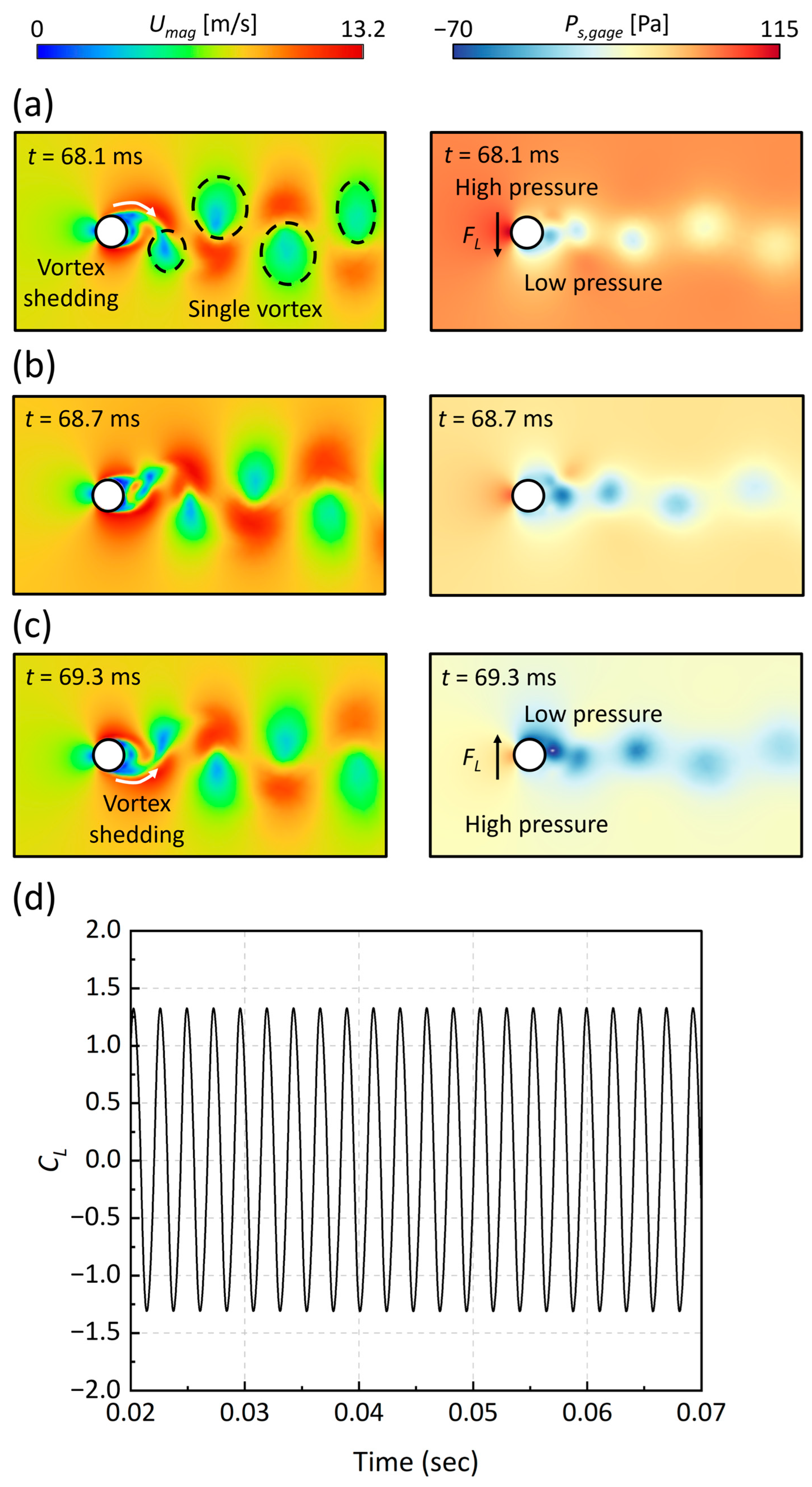
The CFD results of the transient changes in velocity (U) and static pressure (Ps,gage) around the MEMS energy harvester, illustrating the lift coefficient (CL) evolution at an inlet velocity of 8.00 m/s, are presented in Figure 3. In this context, we analyzed the variation in the static pressure (Ps) field, emphasizing that Ps represents gauge pressure, due to its direct impact on the variation in the lift force caused by vortex formation. Between 68.1 ms and 69.3 ms, the formation of single-type vortices encircling the cylindrical oscillator was observed. The shedding of these vortices initiated at the oscillator’s circumferential boundary—referred to as the “top” in the 2D representation—and progressively migrated towards the “middle” and “bottom” regions in the 2D field. This migration led to significant alterations in the adjacent flow and pressure fields. At 68.1 ms, an elevated static pressure, reaching up to 115 Pa on the upper boundary in the 2D plane, generated a force directed towards the oscillator’s center. By 68.7 ms, a more uniform pressure distribution resulted in a neutral force impact on the oscillator. At 69.3 ms, the inversion of the pressure gradient, dropping to as low as −70 Pa, created a force that was directed away from the center. This sequence of dynamic shifts induced substantial lift forces, observable in Figure 3d, where the oscillator experienced periodic, sinusoidal forces, with the lift force coefficient peaking at 1.33.
Our CFD results elucidate that the vortex patterns that are proximal to the oscillator significantly manipulate the flow and pressure distribution, inducing periodic forces that are crucial for effective energy harvesting. These findings suggest that, within a flow environment, the MEMS energy harvester will prompt vertical oscillations in the silicon cantilever beam, which is critical for the harvester’s design to ensure optimal energy extraction.
3.2. Fabrication and Characterization of MEMS Energy Harvester and Piezoelectric Film
Building on the insights from Section 3.1, Figure 4 illustrates our fabrication process for the MEMS chip, tailored to incorporate the parameters from our vortex dynamics studies. The process begins with the cleaning of a 4-inch silicon-on-insulator (SOI) wafer, characterized by a 400 µm thick silicon handle layer, a 1.00 µm thick buried oxide layer, and a 5.00 µm thick p-type silicon device layer, selected for their superior electrical properties and versatility. To protect the device and handle layers during the fabrication and prevent edge oxidation, a protective SiO2 layer, approximately 3000 Å thick, was deposited on both surfaces of the wafer via plasma-enhanced chemical vapor deposition (PECVD).
For the piezoelectric component, aluminum nitride (AlN) was selected despite having a piezoelectric constant (5.5 10−12 C/N at d33) that is approximately 100 time lower than that of lead zirconate titanate (PZT) [37,38]. This choice was made considering AlN’s advantages, such as a reduced contamination risk and greater cost-efficiency [39]. AlN was sputtered to a 5000 Å thickness. The fabrication sequence involved patterning for piezoelectric layer deposition, etching, and a lift-off process to remove superfluous material, culminating in the construction of electrodes from layers of Al (3000 Å) and Cr (200 Å) through evaporation, essential for channeling the piezoelectric film’s electrical output. Here, in the construction process of the electrode, an electron beam (E-beam) evaporator was employed for depositing Al/Cr layers at thicknesses of 3000/200 Å. These layers were deposited atop the upper oxide layer and the sputtered AlN region to form the electrodes. Cr was used as an adhesive layer, which did not affect the AIN performance [40]. Forming a cantilever beam involved etching a specific pattern on the device layer, reactive ion etching down to the buried oxide layer, and the addition of a protective cap. This was followed by backside alignment, etching a masking pattern, and the use of deep reactive ion etching (DRIE) to sculpt the cantilever from the handle layer. The completed MEMS chip, as shown in Figure 4f,g, includes the cantilever beam, piezoelectric film, and electrodes.
The thin AlN film, covered with electrodes and deposited on the silicon cantilever beam (Figure 4g), exhibits varying physical properties based on its crystal orientation. The reactive sputtering process, employed for depositing AlN, requires careful control of the sputtering pressure at 1 Pa and nitrogen gas concentration (50% N2/Ar) to ensure alignment in the (0002) direction [41]. X-ray diffraction (XRD) analysis of our fabricated structure confirmed the successful deposition of the AlN film in the correct orientation, as indicated by the strong intensity peak at the 2θ position of around 36 degrees in Figure 5, corroborating the perpendicular alignment of the film relative to the cantilever beam’s surface [41,42,43]. The final step in the device fabrication involved forming a cylindrical oscillator using a 3D printer. The oscillator made from polylactic acid filament was secured to the cantilever beam with a cyanoacrylate adhesive, measuring 2.00 mm in diameter and 10.0 mm in height.
3.3. Harnessing Wind Energy: Correlating Vortex-Induced Dynamics with Electrical Output
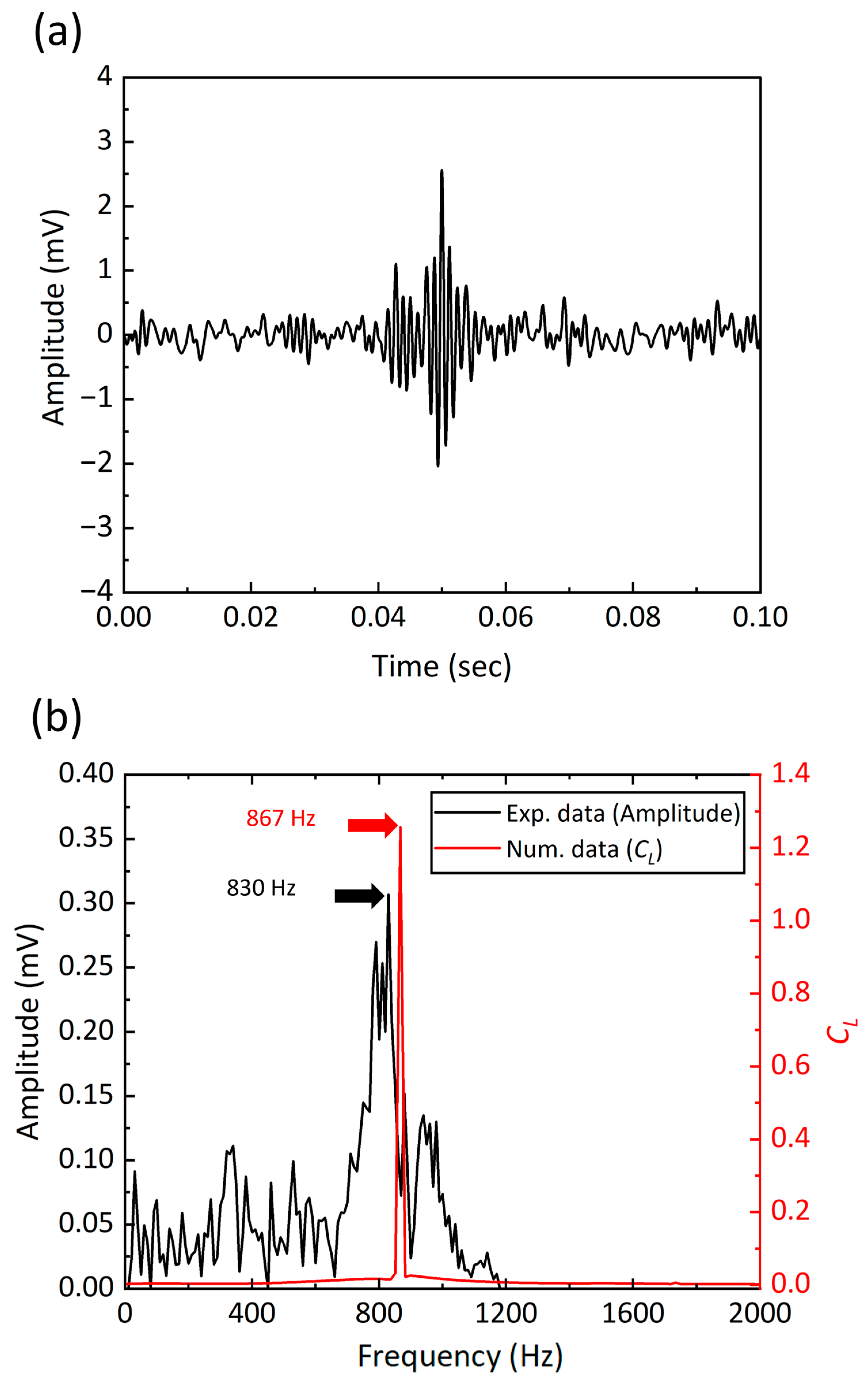
This section investigates the harvester’s ability to harness wind energy and convert it into electrical energy. As evidenced by the generated AC voltage signals presented in Figure 6a, we observed distinct voltage signal generations across the time and frequency domains during the wind tunnel test. A notable peak at approximately 2.56 mV at around 50 ms is a clear indicator of the harvester’s ability to effectively capture wind energy. To ensure that this response is due to the changes in the vortex-induced lift force, we conducted a comparative analysis, correlating the experimental AC voltage signals with the lift force frequencies deduced from our numerical studies. Employing fast Fourier transform (FFT) analyses on both sets of data revealed dominant frequencies at 830 Hz and 867 Hz, as indicated in Figure 6b. The slight variance between the experimental frequency and the CFD-derived frequency points to minor discrepancies in the vortex formation around the MEMS chip, affecting the overall vortex shedding behavior.
The Strouhal number (St), a key dimensionless quantity in fluid dynamics, was assessed to validate the power signal’s reliability and consistency. This number, which ties the vortex shedding frequency to flow characteristics, is defined as follows [44]:
where f represents the vortex shedding frequency of the flow. In this context, it is essential to clarify that the “vortex shedding frequency” pertains exclusively to the frequency at which vortices are shed by the fluid flow, distinctly separate from the oscillation frequency of the structural. Considering the Reynolds number variations, the Strouhal number was experimentally determined to be approximately 0.21, resonating with the fluidic conditions and an inlet velocity of 8.00 m/s (Re = 1095) [44,45,46]. This led to a calculated vortex shedding frequency of around 840 Hz, closely aligning with the FFT analysis outcomes and affirming the influence of the vortex behavior on the electrical output of the harvester.
We observed a voltage signal from the MEMS energy harvester of 2.56 mV at 830 Hz. By comparing the frequencies of vortex shedding, excitation (i.e., voltage), and lift force at 8 m/s, we demonstrated its applicability in actual flow environments. When designing piezoelectric MEMS energy harvesters, materials like PZT and AlN are considered. Although PZT is often favored for its superior piezoelectric efficiency [38], allowing vibrational energy harvesters to generate power ranging from 1 μW to 100 μW [16,17,18], it poses specific challenges in fabrication due to contamination risks during the deposition process. Conversely, while AlN exhibits lower piezoelectric properties, it is considered more feasible for MEMS fabrication due to its ease of processing [39], typically generating power at mV levels in the nW to μW range [19,20]. The relatively low power output from these harvesters presents challenges in electrical circuit functions, including rectification. Nonetheless, extensive research has been undertaken to enhance and convert power from the mV and nW-μW levels to scales that are practical for energy harvesting [21,22].
Methods to enhance performance include minimizing residual stresses on piezoelectric materials through precision micromachining processes and controlling Karman vortex patterns. In the process of harvesting wind energy, the AlN piezoelectric film, which is essential for converting mechanical energy into electrical energy, experiences changes in its coupling coefficient due to residual stresses induced during micromachining [47,48]. Increased residual stresses result in reduced coupling coefficients of the piezoelectric elements, subsequently impairing the performance of energy capture [48]. Therefore, addressing the challenges in micromachining to control or mitigate these residual stresses is crucial for enhancing the operational efficiency and energy harvesting capabilities of our MEMS energy harvester. Additionally, our computational fluid dynamics (CFD) studies reveal that a single vortex type predominates in the wake of the MEMS energy harvester, as depicted in Figure 3. By modifying the arrangement or the surface of the cylinder to promote the formation of combined single and pair of vortex patterns, we anticipate a possible increase in the amplitude of the voltage produced by the MEMS energy harvester [49].
4. Conclusions
In summary, we presented an MEMS energy harvester for capturing the flow-induced vibration caused by the Karman vortex. We designed and fabricated a 5 µm thick silicon cantilever beam coated with AlN piezoelectric film through MEMS processes. The alignment of the piezoelectric film was verified through an XRD test. The fluctuating static pressure field around the oscillator, induced by vortex formation, is the primary driver of the cantilever beam’s vibrations. The robust correlation between the wind-tunnel-derived voltage signals and the CFD lift force coefficients, especially regarding frequency alignment, as denoted by the Strouhal number, not only validates the harvester’s operational efficacy but also emphasizes the importance of flow field control in enhancing energy harvesting performance.
The ability of our energy harvester to transform wind-induced vibrations into electrical energy with substantial voltage outputs suggests the harvester’s practical applicability. A notable peak at approximately 2.56 mV at 830 Hz was a clear indicator of the harvester’s capability to effectively capture wind energy. The observed voltage generation is not just a measure of the device’s operational capability but also reflects its alignment with the anticipated performance. The dominant frequencies within the 830 Hz to 867 Hz range closely align with the theoretical analysis of vortex shedding dynamics. This agreement of experimental results with theoretical models solidifies our research methodology and supports the significance of precise modeling in the conceptualization of effective harvesting mechanisms.
In sum, our findings not only elucidate the operational potential of MEMS energy harvesters but also lay the groundwork for subsequent innovation in the field of renewable energy technologies. Additionally, the suggested energy harvesting method is significantly influenced by fluid dynamics, the shape of the energy harvester, resonance phenomena, and structural characteristics. So, if optimal design is achieved in future works, it could lead to enhanced energy harvesting. The implications of our work possibly extend into the realm of sustainable energy solutions and low-power wireless sensors, where the application of MEMS technology could potentially play a transformative role.
Author Contributions
Conceptualization, J.G.K., H.K. and S.S.; Methodology, J.G.K. and H.K.; Validation, J.G.K., H.K. and S.S.; Investigation, J.G.K. and H.K.; Writing—original draft, J.G.K. and H.K.; Writing—review and editing, S.S. and B.S.K.; Visualization, B.S.K.; Supervision, B.S.K.; Project administration, B.S.K. All authors have read and agreed to the published version of the manuscript.
Funding
This study was financially supported by Seoul National University of Science and Technology.
Data Availability Statement
The original contributions presented in the study are included in the article, further inquiries can be directed to the corresponding author.
Conflicts of Interest
The authors declare no conflicts of interest.
References
- Liu, D.; Chen, B.; An, J.; Li, C.; Liu, G.; Shao, J.; Tang, W.; Zhang, C.; Wang, Z.L. Wind-Driven Self-Powered Wireless Environmental Sensors for Internet of Things at Long Distance. Nano Energy 2020, 73, 104819. [Google Scholar] [CrossRef]
- Huang, J.; Fu, X.; Liu, G.; Xu, S.; Li, X.; Zhang, C.; Jiang, L. Micro/Nano-Structures-Enhanced Triboelectric Nanogenerators by Femtosecond Laser Direct Writing. Nano Energy 2019, 62, 638–644. [Google Scholar] [CrossRef]
- Kamalinejad, P.; Mahapatra, C.; Sheng, Z.; Mirabbasi, S.; Leung, V.C.M.; Guan, Y.L. Wireless Energy Harvesting for the Internet of Things. IEEE Commun. Mag. 2015, 53, 102–108. [Google Scholar] [CrossRef]
- Dinesh Ram, G.; Praveen Kumar, S.; Yuvaraj, T.; Sudhakar Babu, T.; Balasubramanian, K. Simulation and Investigation of MEMS Bilayer Solar Energy Harvester for Smart Wireless Sensor Applications. Sustain. Energy Technol. Assess. 2022, 52, 102102. [Google Scholar] [CrossRef]
- Todaro, M.T.; Guido, F.; Mastronardi, V.; Desmaele, D.; Epifani, G.; Algieri, L.; De Vittorio, M. Piezoelectric MEMS Vibrational Energy Harvesters: Advances and Outlook. Microelectron. Eng. 2017, 183–184, 23–36. [Google Scholar] [CrossRef]
- Li, H.; Tian, C.; Deng, Z.D. Energy Harvesting from Low Frequency Applications Using Piezoelectric Materials. Appl. Phys. Rev. 2014, 1, 041301. [Google Scholar] [CrossRef]
- Ejeian, F.; Azadi, S.; Razmjou, A.; Orooji, Y.; Kottapalli, A.; Ebrahimi Warkiani, M.; Asadnia, M. Design and Applications of MEMS Flow Sensors: A Review. Sens. Actuator A-Phys. 2019, 295, 483–502. [Google Scholar] [CrossRef]
- Barzegar, M.; Blanks, S.; Sainsbury, B.-A.; Timms, W. MEMS Technology and Applications in Geotechnical Monitoring: A Review. Meas. Sci. Technol. 2022, 33, 052001. [Google Scholar] [CrossRef]
- Bouma, A.; Le, E.; Vasconcellos, R.; Abdelkefi, A. Effective Design and Characterization of Flutter-Based Piezoelectric Energy Harvesters with Discontinuous Nonlinearities. Energy 2022, 238, 121662. [Google Scholar] [CrossRef]
- Liang, H.; Hao, G.; Olszewski, O.Z. A Review on Vibration-Based Piezoelectric Energy Harvesting from the Aspect of Compliant Mechanisms. Sens. Actuator A-Phys. 2021, 331, 112743. [Google Scholar] [CrossRef]
- Pan, D.; Dai, F. Design and Analysis of a Broadband Vibratory Energy Harvester Using Bi-Stable Piezoelectric Composite Laminate. Energy Conv. Manag. 2018, 169, 149–160. [Google Scholar] [CrossRef]
- Batra, N.; Deol, R.S.; Singh, M.; Mitra, B. Mechanically Coupled Cantilever Beam Structure for Piezoelectric Energy Harvesting. J. Micromech. Microeng. 2023, 33, 034001. [Google Scholar] [CrossRef]
- Calautit, K. State-of-the-Art Review of Micro to Small-Scale Wind Energy Harvesting Technologies for Building Integration. Energy Conv. Manag. 2023, 20, 100457. [Google Scholar] [CrossRef]
- Khalid, S.; Raouf, I.; Khan, A.; Kim, N.; Kim, H.S. A Review of Human-Powered Energy Harvesting for Smart Electronics: Recent Progress and Challenges. Int. J. Precis. Eng. Manuf.-Green Technol. 2019, 6, 821–851. [Google Scholar] [CrossRef]
- Tan, Y.; Dong, Y.; Wang, X. Review of MEMS Electromagnetic Vibration Energy Harvester. J. Microelectromech. Syst. 2017, 26, 1–16. [Google Scholar] [CrossRef]
- Yu, H.; Zhou, J.; Deng, L.; Wen, Z. A Vibration-Based MEMS Piezoelectric Energy Harvester and Power Conditioning Circuit. Sensors 2014, 14, 3323–3341. [Google Scholar] [CrossRef] [PubMed]
- Tian, Y.; Li, G.; Yi, Z.; Liu, J.; Yang, B. A Low-Frequency MEMS Piezoelectric Energy Harvester with a Rectangular Hole Based on Bulk PZT Film. J. Phys. Chem. Solids 2018, 117, 21–27. [Google Scholar] [CrossRef]
- Wang, F.; Zhou, M.; Wu, P.; Gao, L.; Chen, X.; Mu, X. Self-Powered Transformer Intelligent Wireless Temperature Monitoring System Based on an Ultra-Low Acceleration Piezoelectric Vibration Energy Harvester. Nano Energy 2023, 114, 108662. [Google Scholar] [CrossRef]
- Algieri, L.; Todaro, M.T.; Guido, F.; Mastronardi, V.; Desmaële, D.; Qualtieri, A.; Giannini, C.; Sibillano, T.; De Vittorio, M. Flexible Piezoelectric Energy-Harvesting Exploiting Biocompatible AlN Thin Films Grown onto Spin-Coated Polyimide Layers. ACS Appl. Energy Mater. 2018, 1, 5203–5210. [Google Scholar] [CrossRef]
- Abouzarkhanifard, A.; Chimeh, H.E.; Janaideh, M.A.; Zhang, L. FEM-Inclusive Transfer Learning for Bistable Piezoelectric MEMS Energy Harvester Design. IEEE Sens. J. 2023, 23, 3521–3531. [Google Scholar] [CrossRef]
- Wang, H.; Tang, Y.; Khaligh, A. A Bridgeless Boost Rectifier for Low-Voltage Energy Harvesting Applications. IEEE Trans. Power Electron. 2013, 28, 5206–5214. [Google Scholar] [CrossRef]
- Peters, C.; Handwerker, J.; Maurath, D.; Manoli, Y. An Ultra-Low-Voltage Active Rectifier for Energy Harvesting Applications. In Proceedings of the 2010 IEEE International Symposium on Circuits and Systems, Paris, France, 30 May–2 June 2010; IEEE: Paris, France, 2010; pp. 889–892. [Google Scholar]
- Blad, T.W.A.; Machekposhti, D.F.; Herder, J.L.; Holmes, A.S.; Tolou, N. Vibration Energy Harvesting from Multi-Directional Motion Sources. In Proceedings of the 2018 International Conference on Manipulation, Automation and Robotics at Small Scales (MARSS), Nagoya, Japan, 4–8 July 2018; IEEE: Nagoya, Japan, 2018; pp. 1–9. [Google Scholar]
- Beeby, S.P.; Torah, R.N.; Tudor, M.J.; Glynne-Jones, P.; O’Donnell, T.; Saha, C.R.; Roy, S. A Micro Electromagnetic Generator for Vibration Energy Harvesting. J. Micromech. Microeng. 2007, 17, 1257–1265. [Google Scholar] [CrossRef]
- Song, J.; Sun, G.; Zeng, X.; Li, X.; Bai, Q.; Zheng, X. Piezoelectric Energy Harvester with Double Cantilever Beam Undergoing Coupled Bending-Torsion Vibrations by Width-Splitting Method. Sci. Rep. 2022, 12, 583. [Google Scholar] [CrossRef]
- Karadag, C.V.; Topaloglu, N. A Self-Sufficient and Frequency Tunable Piezoelectric Vibration Energy Harvester. J. Vib. Acoust. Trans. ASME 2017, 139, 011013. [Google Scholar] [CrossRef]
- Ferrari, M.; Ferrari, V.; Guizzetti, M.; Andò, B.; Baglio, S.; Trigona, C. Improved Energy Harvesting from Wideband Vibrations by Nonlinear Piezoelectric Converters. Sens. Actuator A-Phys. 2010, 162, 425–431. [Google Scholar] [CrossRef]
- He, X.-F.; Gao, J. Wind Energy Harvesting Based on Flow-Induced-Vibration and Impact. Microelectron. Eng. 2013, 111, 82–86. [Google Scholar] [CrossRef]
- Lee, Y.J.; Qi, Y.; Zhou, G.; Lua, K.B. Vortex-Induced Vibration Wind Energy Harvesting by Piezoelectric MEMS Device in Formation. Sci. Rep. 2019, 9, 20404. [Google Scholar] [CrossRef]
- Wang, J.; Yurchenko, D.; Hu, G.; Zhao, L.; Tang, L.; Yang, Y. Perspectives in Flow-Induced Vibration Energy Harvesting. Appl. Phys. Lett. 2021, 119, 100502. [Google Scholar] [CrossRef]
- Hu, Y.; Yang, B.; Chen, X.; Wang, X.; Liu, J. Modeling and Experimental Study of a Piezoelectric Energy Harvester from Vortex Shedding-Induced Vibration. Energy Conv. Manag. 2018, 162, 145–158. [Google Scholar] [CrossRef]
- Zhang, L.; Meng, B.; Tian, Y.; Meng, X.; Lin, X.; He, Y.; Xing, C.; Dai, H.; Wang, L. Vortex-Induced Vibration Triboelectric Nanogenerator for Low Speed Wind Energy Harvesting. Nano Energy 2022, 95, 107029. [Google Scholar] [CrossRef]
- He, X.; Yang, X.; Jiang, S. Enhancement of Wind Energy Harvesting by Interaction between Vortex-Induced Vibration and Galloping. Appl. Phys. Lett. 2018, 112, 033901. [Google Scholar] [CrossRef]
- Junqiang, L.; Yiling, Y.; Chuanyu, W.; Guoping, L.; Tehuan, C.; Jianqiang, M. Underwater Oscillation Performance and 3D Vortex Distribution Generated by Miniature Caudal Fin-like Propulsion with Macro Fiber Composite Actuation. Sens. Actuators A-Phys. 2020, 303, 111587. [Google Scholar] [CrossRef]
- Pankanin, G.L.; Kulińczak, A.; Berliński, J. Investigations of Karman Vortex Street Using Flow Visualization and Image Processing. Sens. Actuators A-Phys. 2007, 138, 366–375. [Google Scholar] [CrossRef]
- Ramírez, J.M. A Coupled Formulation of Fluid-Structure Interaction and Piezoelectricity for Modeling a Multi-Body Energy Harvester from Vortex-Induced Vibrations. Energy Conv. Manag. 2021, 249, 114852. [Google Scholar] [CrossRef]
- Ali, W.R.; Prasad, M. Piezoelectric MEMS Based Acoustic Sensors: A Review. Sens. Actuators A-Phys. 2020, 301, 111756. [Google Scholar] [CrossRef]
- Fawzy, A.; Zhang, M. Piezoelectric Thin Film Materials for Acoustic MEMS Devices. In Proceedings of the 2019 6th International Conference on Advanced Control Circuits and Systems (ACCS) & 2019 5th International Conference on New Paradigms in Electronics & information Technology (PEIT), Hurgada, Egypt, 17–20 November 2019; IEEE: Hurgada, Egypt, 2019; pp. 82–86. [Google Scholar]
- Panda, P.K.; Sahoo, B. PZT to Lead Free Piezo Ceramics: A Review. Ferroelectrics 2015, 474, 128–143. [Google Scholar] [CrossRef]
- Tytko, D.; Choi, P.-P.; Raabe, D. Oxidation Behavior of AlN/CrN Multilayered Hard Coatings. Nano Converg. 2017, 4, 15. [Google Scholar] [CrossRef] [PubMed]
- Lee, H.-C.; Lee, J.-Y. Effects of Sputtering Pressure and Nitrogen Concentration on the Preferred Orientation of AlN Thin Films. J. Mater. Sci.-Mater. Electron. 1994, 5, 221–225. [Google Scholar] [CrossRef]
- Tran, A.T.; Wunnicke, O.; Pandraud, G.; Nguyen, M.D.; Schellevis, H.; Sarro, P.M. Slender Piezoelectric Cantilevers of High Quality AlN Layers Sputtered on Ti Thin Film for MEMS Actuators. Sens. Actuator A-Phys. 2013, 202, 118–123. [Google Scholar] [CrossRef]
- Lee, J.-B.; Cho, D.-H.; Kim, D.-Y.; Park, C.-K.; Park, J.-S. Relationships between Material Properties of Piezo-Electric Thin Films and Device Characteristics of Film Bulk Acoustic Resonators. Thin Solid Films 2007, 516, 475–480. [Google Scholar] [CrossRef]
- Williamson, C.H.K. Vortex Dynamics in the Cylinder Wake. Annu. Rev. Fluid Mech. 1996, 28, 477–539. [Google Scholar] [CrossRef]
- Bai, H.; Alam, M.M. Dependence of Square Cylinder Wake on Reynolds Number. Phys. Fluids 2018, 30, 015102. [Google Scholar] [CrossRef]
- Zahari, M.; Chan, H.B.; Yong, T.H.; Dol, S.S. The Effects of Spring Stiffness on Vortex-Induced Vibration for Energy Generation. IOP Conf. Ser. Mater. Sci. Eng. 2015, 78, 012041. [Google Scholar] [CrossRef]
- Rezaeisaray, M.; El Gowini, M.; Sameoto, D.; Raboud, D.; Moussa, W. Wide-Bandwidth Piezoelectric Energy Harvester with Polymeric Structure. J. Micromech. Microeng. 2015, 25, 015018. [Google Scholar] [CrossRef]
- Ong, R.J.; Payne, D.A.; Sottos, N.R. Processing Effects for Integrated PZT: Residual Stress, Thickness, and Dielectric Properties. J. Am. Ceram. Soc. 2005, 88, 2839–2847. [Google Scholar] [CrossRef]
- Morse, T.L.; Williamson, C.H.K. Fluid Forcing, Wake Modes, and Transitions for a Cylinder Undergoing Controlled Oscillations. J. Fluids Struct. 2009, 25, 697–712. [Google Scholar] [CrossRef]
Figure 1.
Schematics of energy harvesters: (a) Traditional MEMS-based vibration harvester with a piezoelectric cantilever beam and a proof mass. (b) Conceptual design of a wind energy harvester utilizing flow-induced vibrations. (c) Proposed integrated MEMS energy harvester incorporating a cylindrical oscillator for enhanced efficiency.

Figure 2.
Aerodynamic force analysis and experimental setup: (a) Computational domain for aerodynamic force analysis of the cylinder. (b) Wind tunnel setup illustrating the arrangement of the blower, inverter, measurement instruments, and the test section for harvester performance evaluation.
Figure 2.
Aerodynamic force analysis and experimental setup: (a) Computational domain for aerodynamic force analysis of the cylinder. (b) Wind tunnel setup illustrating the arrangement of the blower, inverter, measurement instruments, and the test section for harvester performance evaluation.

Figure 3.
Fluid dynamics around the oscillator: (a–c) Transitional changes in the velocity and static pressure fields around an oscillator at an inlet velocity of 8.00 m/s (Re = 1095), depicting the influence on the lift force coefficient (CL). (d) Time domain signal of the CL, demonstrating its variation over time.

Figure 4.
MEMS chip fabrication process: (a) SiO2 layer patterning for the piezoelectric AlN film deposition. (b) AlN film deposition. (c) Electrode layer deposition for electrical output. (d) Formation of the cantilever structure through reactive ion etching (RIE). (e) Finalization of the cantilever with back-side alignment and deep reactive ion etching (DRIE). (f) A schematic and (g) photograph of the completed MEMS chip with cantilever beam, piezoelectric film, and electrodes.

Figure 5.
X-ray diffraction (XRD) analysis of the fabricated MEMS structure. Strong intensity peak at the 2θ position of around 36 degrees confirms the successful deposition of the AlN film in the (0002) orientation.
Figure 5.
X-ray diffraction (XRD) analysis of the fabricated MEMS structure. Strong intensity peak at the 2θ position of around 36 degrees confirms the successful deposition of the AlN film in the (0002) orientation.

Figure 6.
Output AC voltage signal and frequency analysis: (a) Time domain representation of the output AC voltage signal, showing variation and peak amplitude over time. (b) Frequency spectrum from FFT analysis, comparing experimental voltage with numerical simulation results for lift force coefficient (CL), indicating dominant frequencies at 830 Hz and 867 Hz.

Disclaimer/Publisher’s Note: The statements, opinions and data contained in all publications are solely those of the individual author(s) and contributor(s) and not of MDPI and/or the editor(s). MDPI and/or the editor(s) disclaim responsibility for any injury to people or property resulting from any ideas, methods, instructions or products referred to in the content. |
© 2024 by the authors. Licensee MDPI, Basel, Switzerland. This article is an open access article distributed under the terms and conditions of the Creative Commons Attribution (CC BY) license (https://creativecommons.org/licenses/by/4.0/).
Share and Cite
MDPI and ACS Style
Kang, J.G.; Kim, H.; Shin, S.; Kim, B.S. Fluid Flow to Electricity: Capturing Flow-Induced Vibrations with Micro-Electromechanical-System-Based Piezoelectric Energy Harvester. Micromachines 2024, 15, 581. https://doi.org/10.3390/mi15050581
AMA Style
Kang JG, Kim H, Shin S, Kim BS. Fluid Flow to Electricity: Capturing Flow-Induced Vibrations with Micro-Electromechanical-System-Based Piezoelectric Energy Harvester. Micromachines. 2024; 15(5):581. https://doi.org/10.3390/mi15050581
Chicago/Turabian StyleKang, Jin Gu, Hyeukgyu Kim, Sangwoo Shin, and Beom Seok Kim. 2024. "Fluid Flow to Electricity: Capturing Flow-Induced Vibrations with Micro-Electromechanical-System-Based Piezoelectric Energy Harvester" Micromachines 15, no. 5: 581. https://doi.org/10.3390/mi15050581
Note that from the first issue of 2016, this journal uses article numbers instead of page numbers. See further details here.