
Multilevel Aircraft-Inverter Design Based on Wavelet PWM for More Electric Aircraft


1
Faculty of Engineering, Department of Electrical and Electronics Engineering, Ankara University, Ankara 06830, Turkey
2
Faculty of Engineering, Department of Electrical and Electronics Engineering, OSTIM Technical University, Ankara 06374, Turkey
*
Author to whom correspondence should be addressed.
Energies 2024, 17(9), 2054; https://doi.org/10.3390/en17092054
Submission received: 14 March 2024
/
Revised: 3 April 2024
/
Accepted: 24 April 2024
/
Published: 26 April 2024
(This article belongs to the Special Issue Power Electronics Converters for On-Board Electric Power Systems)
Abstract
:This paper proposes a comprehensive power system designed for the use of a more electric aircraft power distribution system. Instead of traditional Nicad battery solutions as the energy source of the aircraft power system, lithium battery structures, which are a recent and promising solution in the field of aviation power systems, are modeled and analyzed. In this study, a WPWM-based, single-phase, multi-level pure sine wave static aircraft-inverter system is designed and integrated to improve the performance of conventional aircraft power systems. In the designed power system, a boost converter structure is proposed that boosts 28 VDC-to-270 VDC voltage coming from the lithium–ion battery pack and can reach a steady state in 0.032 s. The performance of the modeled WPWM-based aircraft-inverter system, compared to SPWM Bipolar and Unipolar switching techniques commonly used in single-phase inverter designs, reveals a THD reduction of approximately 27% with WPWM, resulting in a THD value below 2% for both load current and load voltage. As a result of the study, a power system that will enable the aircraft avionics, ventilation, and navigation systems to perform better than conventional power systems and comply with aircraft electric-power characteristic standards has been designed and detailed.
1. Introduction
Research in the field of aviation is increasingly focusing on electrification systems for a cleaner environment, an efficient, more accessible, and rapid system, and increased safety [1]. Therefore, the conversion of hydraulic, pneumatic, and mechanical systems in the structure of conventional aircraft into electrical systems requires the use of new technologies [2]. The processes of realizing this transformation are examined in the literature under the concepts called more electric aircraft (MEA) and all-electric aircraft (AEA). These concepts can also be defined as the new direction and rising trend of the aviation system in terms of energy [3,4]. Recent academic work in the field of power electronics for aircraft systems is primarily focused on improving system efficiency, adapting circuits for aircraft use, and achieving higher capacity [5]. These efforts aim to realize systems that offer advantages in terms of volume, weight, and efficiency, which are crucial factors for aircraft MEA systems. Current research in this scope focuses primarily on improving the performance of electronic systems by efficiently converting and controlling electrical energy in aircraft applications. This includes optimizing power supplies for better efficiency and developing subsystems that can transmit energy more effectively to other aircraft systems.
In the literature, there are several studies on the development of electrical power systems for aircraft utilizing inverters. These are generally aimed at developing innovative switching topologies or improving the overall efficiency. Zhen Huang et al. examined dual-inverter topologies to meet the requirements of MEA applications in their study. They developed this topology by selecting three performance elements: voltage utilization, inverter output quality, and fault tolerance [6]. Janine Ebersberger et al. have compared two-level and three-level inverters regarding the power increase of aircraft within the scope of MEA [7]. In another study, which is related to the following concept, the loss model was derived using the silicon carbide (SiC) metal–oxide–semiconductor field-effect transistor (MOSFET) as a semi-conductor element and was used to predict the properties of voltage levels.
In aircraft power systems, it is common to use a frequency of 400 Hz in inverter applications due to its advantageous characteristics compared to the standard 50/60 Hz frequency [8]. The adoption of higher frequencies allows for lighter and more efficient components to be integrated into electrical systems. This is mainly due to the feasibility of using smaller and lighter transformers and inductors for electric motors and various electronic devices. As a result, this reduction in component size and weight contributes to a reduction in the overall weight of the aircraft, improving fuel efficiency. Furthermore, the use of higher frequencies facilitates faster transmission of electrical energy, enabling aircraft electrical systems to exhibit greater response and precision. Using high frequencies instead of 400 Hz offers various efficiency advantages but is still considered experimental in terms of standards and generality of use.
Himanshu Saini et al. have created a five-level inverter model to meet the energy demand for MEA applications [9]. Instead of using the traditional 400 Hz output frequency, they chose a frequency of 1.4 kHz to reduce the weight of the motor. Fei Diao et al. designed a hybrid multilevel inverter composed of Si and SiC for electric aircraft applications [10]. In addition to high-power efficiency, a harmonics-reduced system, lower dv/dt ratio, and a low-cost space vector-modulation technique are also proposed in the study. In this study, we aim to design a single-phase aircraft inverter with high efficiency and optimum total harmonic distortion (THD) level based on the developing semiconductor technology.
Based on the literature research, there are hydraulic, pneumatic, and electrical power structures as secondary power usage, especially in civil aircraft. However, current studies and market trends show that efforts to replace hydraulic and pneumatic systems with electrical power systems are gaining momentum [11]. The main reasons for this are the low efficiency of hydraulic systems, their long production and design processes, and the fact that they are more difficult to control than electrical systems. Pneumatic systems share common drawbacks such as weight and space constraints, slow response time, complexity and maintenance requirements, and temperature sensitivity. It is expected that the use of electrical systems in aircraft will accelerate as these disadvantages can be solved to a significant extent by increasing the use of electrical systems in aircraft. This transformation process is likely to be characterized by the concept of MEA in the first phase and all-electric aircraft as a commercially prominent option in the steady state.
2. More Electric Aircraft
The concept of MEA emerged in 1995 due to research provided in [12]. This concept represents an essential area of aircraft innovation, as advances in aircraft technology have made systems more sophisticated. MEA aims to provide as much electrical energy as possible to the aircraft. Today, it is argued that MEA technology is one of the most promising technologies for the aviation industry to reduce aircraft weight and fuel use [13]. MEA technology is generally created by converting the hydraulic, mechanical, and pneumatic circuits and loads in conventional aircraft into integrated and partial electrical sources [14]. MEA systems benefit aircraft significantly in important areas, such as significant fuel savings, lower environmental impact (carbon emissions etc.), better maintenance, more reliability, higher power density, system continuity, more appropriate volume, and weight, and reduced cost [15].
Figure 1 depicts an overview of the power distribution scheme in a conventional aircraft and an aircraft with an MEA system. The conventional aircraft structure in Figure 1a is not the right structure for remote power distribution. As can be seen from the figure, in a conventional aircraft, power generation, distribution, and utilization for electrical, pneumatic, hydraulic, and mechanical systems are performed separately, and there is no connection between these subsystems. With the MEA concept in the structure in Figure 1b, all pneumatic, hydraulic, and mechanical loads provide the necessary power from a single electrical power distribution system [16]. In Figure 1a, motor-driven generator systems provide the required electrical power for all loads. In this case, applying power with different voltage levels to all the loads specified is necessary. The systems that will provide this are electronic power circuits, which obtain different voltage levels in both DC and AC [17]. For this reason, some of the pneumatic, hydraulic, and mechanical systems are being converted into electrical systems that reduce overall weight, cost, and environmental impact and increase efficiency. In this way, as the technology evolves, fewer mechanical connections and hydraulic power sources are used, significantly reducing the maintenance complexity. By adopting and effectively implementing the MEA system, silent and fuel-efficient aircraft can be created.
Table 1 shows a comparison of conventional and MEA aircraft. The aviation industry is taking steps to reduce the use of carbon-based fuels, lower emissions, and improve energy efficiency. Furthermore, the electrification system provides criteria such as favorable operation and maintenance costs, noise reduction, and safety. To achieve all these positive features, MEA uses electro-hydrostatic actuators (EHA) and electromechanical actuators (EMA) instead of hydraulic systems as in conventional aircraft [18,19]. As the name suggests, the working principle of the EHA is to convert the available electrical energy into hydraulic power and then convert the hydraulic power into mechanical energy. The EMA is a mechatronic device and is the output command signal of the controller or drives, the load, and other mechanical components in the system.
As shown in Table 1, power systems, especially MEA, play a critical role in the electrical architecture of the aircraft. These systems control the load management of the entire aircraft, covering both power generation and distribution in MEA structures [21]. The aircraft’s power system, consisting of power and distribution systems, is responsible for generating the electrical energy required to operate the various on-board equipment. These systems include components such as motors, motor drives, generators, controllers, and electronic power circuits. Inverters, DC–DC converters, and rectifiers stand out as the most used circuits in the aircraft power system. The primary purpose of these components is to efficiently distribute the power generated by the system to all electrical loads required for the aircraft to operate throughout its flight phases [22].
An advance in MEA systems, and one that is expected to find much more wide-spread use in the future, is AEA systems. Aircraft account for about 2.5% of global CO2 emissions, but their overall contribution to climate change is much higher than this [23]. This is because aircraft do not only emit CO2 but also emit other gases and indirectly affect global warming in a negative way at some points. Based on innovative global warming studies, it has been determined that the negative impact of aircraft on global warming is 3.5%, which is much higher than the Radiative Forcing concept [24]. At this point, MEA and future AEA structures will be of utmost importance for sustainable air transportation. Airplanes in all-electric aircraft systems are propelled by engines that operate totally on electricity. However, the practical application of these technologies is severely constrained because of the difficulties in producing enough thrust for commercial aviation, which accounts for an important percentage of the aviation sector. As a result, AEA structures are now mostly utilized for small-scale or experimental aircraft structures. Due to technological advancements and the need to minimize emission rates, AEA structures can be defined as the future technology for aircraft systems after MEA structures. Thanks to technological developments, the need for electricity increases depending on the type of signal desired in aircraft, and the importance of systems, such as inverters that provide electricity to the system, is increasing in power electronics systems used in aircraft.
The electrical energy distribution system of more electric aircraft is provided in Figure 2 [25]. This study was performed to develop a power system within the boundaries of the MEA energy distribution system.
Lead-acid and Nicad (nickel–cadmium)-based battery solutions are conventionally preferred in aircraft battery systems. However, within the scope of the concept of more electric aircraft, there are innovative studies on the use of lithium ion-based batteries instead of such battery structures [26]. The use of lithium ion-based battery types in aircraft instead of conventional battery structures has several advantages, including weight advantages and the ability to meet instantaneous high current demand. It is predicted that lithium battery technologies will find more and more space in future studies within the scope of more electric aircraft. This is mainly because they are much lighter and significantly smaller in volume than Nicad battery systems. In terms of specific energy density, lithium battery technologies have values of 200 Wh/kg, while this value is around 70 Wh/kg for Nicad. In terms of volumetric energy density, lithium battery technologies have a value of 350 Wh/L, while Nicad battery technologies have a value of 120 Wh/L. With this information, it is seen that the approximate battery pack of an aircraft system in which power systems are energized using lithium battery technologies is approximately three times lighter and occupies much less volume than Nicad [27].
As with other vehicles, ensuring the safety of lithium batteries is critical, particularly in aviation applications. Lithium batteries pose a risk of combustion or explosion if subjected to conditions such as overheating, overcharging, or physical damage, which could have catastrophic consequences for aircraft safety. To mitigate such risks, nanophosphate lithium-ion battery structures, known for their enhanced chemical stability, are favored in aircraft over traditional metal oxide lithium–ion structures [28].
With the relevant inverter structure, AC energy required for structures such as equipment cooling fans, window heaters, and ventilation systems can be provided. In the aircraft, subsystems such as general electronic systems, avionics equipment in the cockpit, navigation systems, flight control systems, and communication equipment operate with AC energy [29]. Considering the systems it operates and the importance of their use with other systems in aircraft, it is crucial to generate AC energy with high efficiency using batteries. To convert the 28 VDC voltage obtained from the battery into 115 VAC 400 Hz voltage, the voltage level must first be increased. As shown in Figure 2, DC/DC converters are used at this stage. Due to the development of semiconductor technology, systems with boost converter structures are preferred instead of transformer structures up to certain power levels. The use of semiconductor switches instead of transformer structures to achieve the desired voltage level in aircraft offers significant advantages and follows the MEA concept. These advantages include higher efficiency, better frequency response, more robustness with respect to electrical noise, and much reduced weight and size. The specifications of MIL-STD-704F standards are provided in Table 2, and the voltage transient response of the inverter system is analyzed in accordance with these standards [30].
The inverter is designed to have a 5 kW power output, over 90% efficiency, and 2% total harmonic distortion. It has also been developed to meet the requirements of the aircraft electrical power characteristics standard (MIL-STD-704F). These standards specify the requirements and characteristics of aircraft electrical power supplied at the input terminals of electrical handling equipment and are intended to ensure compatibility between the aircraft electrical system, external power, and airborne handling equipment. If the electrical power supplying the aircraft units has certain characteristics, these units are expected to provide the required performance under all specified operating conditions. The use of these units must not cause any adverse effects or degradation of the electrical power system. In light of this information, the relevant aircraft-inverter system has been designed as a structure with lithium–ion battery technology using semiconductor switches in DC/DC voltage-conversion processes [31]. Design processes in electronic power systems are primarily based on the determination of losses and the desired power level.
3. Inverter Design and Power Loss Calculation
The loss and parameter calculation process, which is aimed to be realized within the scope of aircraft inverter design, is conducted in this article by following the procedure in the flow diagram shown in Figure 3 [32]. At the initial stage of the calculation process, an output power for the inverter of the aircraft must be determined.
Firstly, parameters such as DC voltage level, AC output voltage, and the power factor to be applied to the system are determined. In these processes, the design standards (MIL-STD-704F) applicable to aircraft were considered. The voltage waveform of single-phase or three-phase electrical power-supply systems is sinusoidal, and expected operating limits are provided in Table 2. The circuit scheme of the single-phase three-level inverter system realized in this study is given in Figure 4 [33].
The state of the switches of the single-phase multilevel inverter and their relation to the output voltage are provided in Table 3 [34].
As shown in Table 3, the output voltages of multilevel inverters are more like pure sine wave structures than single-level structures due to the intermediate output voltage levels. Thus, compared to single-level inverters, multilevel inverters offer better efficiency and less harmonic distortion. However, as the inverter level increases, there are disadvantages such as increased power losses, larger device sizes, higher cost, and more complex control and design.
As seen in the circuit diagram provided in Figure 4, in addition to the switching elements, there is an LC filter group at the output of the inverter [35]. LC filters block unwanted frequency components in electronic power circuits, effectively filtering out noise and harmonics while providing clean power output [36]. Depending on the desired output parameters, they smooth the output waveform and minimize parasitic transmission by producing a clean signal in the appropriate frequency range [37]. This study analyzes and simulates LC filter characteristics for aircraft power systems operating at 115 VAC and 400 Hz. The circuit diagram, including the components and parameters of the LC filter circuit and the load structure associated with it, is provided in Figure 5.
When determining the DC voltage level of the inverter output, in addition to the desired output voltage, calculations are made with a tolerance value of 10% for possible transient conditions, and the formula for calculating the VDC value with the specified tolerance value is provided in Equation (1).
In the next phase, the cut-off frequency fc, also known as the resonant frequency, is the frequency limit at which the energy flowing in the system begins to be damped rather than passing directly through [38]. The damping characteristic at the cut-off frequency is an important factor in second-order filter design. The gain can be very large near the cut-off frequency, and this frequency can amplify the noise. The relationship between the cut-off frequency of the low-pass LC filter and the filter elements is provided in Equation (2).
The cut-off frequency of the LC filter should be between five times the fundamental frequency, represented by f, and 0.2 times the sampling frequency, represented by fs, to obtain good system dynamics and avoid resonance problems, as provided in Equation (3) [39].
To determine the values of L and C, a cut-off frequency between the switching frequency and the output frequency of 400 Hz must be determined for aircraft inverter design. To minimize the harmonic distortion, the output impedance of the inverter should be made minimum. Therefore, the capacitor should be at maximum and the inductor at minimum value at a particular cut-off frequency. In this way, both the cost and volumetric size, which are of great importance for aircraft, can be reduced. In the inverter application inspired by a case study, the ripple current of the filter inductor is chosen to be 20% of the peak value of the load current [40]. Smaller L and C parameters are more beneficial since weight and volume are vital criteria for aircraft. In electronic power systems, elevated switching frequencies typically permit the employment of diminutive inductors and capacitors. This phenomenon is attributed to the decrement in energy-storage requisites per duty cycle at augmented frequencies, thereby facilitating a reduction in the physical dimensions of these components [41]. Furthermore, the optimization of inverter efficiency is crucial in their design, especially for applications where energy conservation is of utmost importance. An increase in switching frequencies, while beneficial in reducing the physical size of passive components, concurrently leads to an amplification of switching losses [42]. Considering the change-of-power losses of the inverter depending on the switching frequency, the calculation of the LC filter parameters of the aircraft inverter to be conducted in our study is provided in Equations (4)–(6), respectively.
Following the determination of the LC filter parameters, the inverter-design process proceeds by calculating the switching and conduction losses. In these processes realized through semiconductor switches, it is necessary to select a reference-switching element with a suitable application area for aircraft power system applications. After the determination of the LC filter parameters, semiconductor switches of the inverter system must be determined.
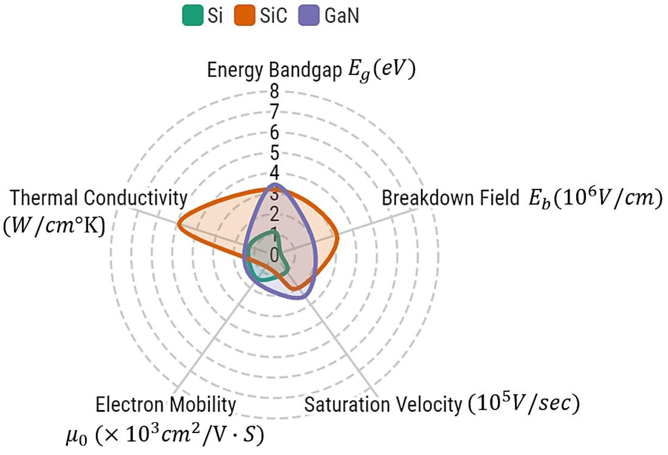
In the selection of semiconductor switching elements, SiC and GaN materials are at the forefront of current electronic power applications, and these two prominent wide bandgap (WBG) semiconductor materials have advantages and disadvantages over each other. Among these two power semiconductor materials, GaN has a slightly higher switching frequency compared to SiC due to higher electron mobility, as shown in Figure 6. Therefore, the GaN structure is more suitable for high-frequency electronic power applications. However, due to the poor thermal conductivity of GaN, it is more commonly used in low-power applications [43].
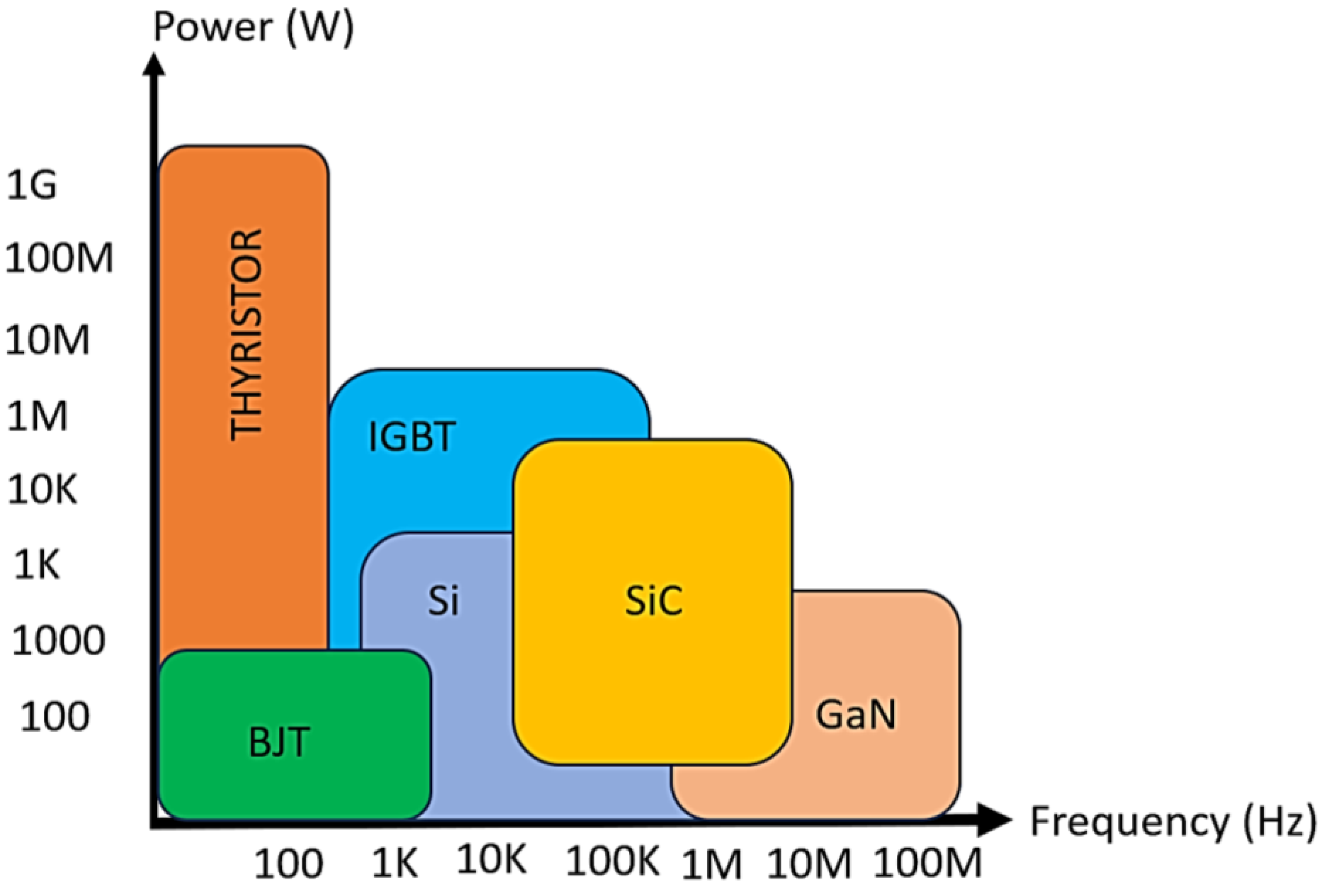
SiC-based semiconductors have much better thermal conductivity and, therefore, lower switching losses at low-to-medium frequencies and are the best choice for high-power applications at medium frequencies. High-thermal conductivity not only dissipates heat faster, but the device can be made smaller, which reduces the form factor, and this advantage also significantly reduces the cooling requirement of the power system. In terms of the applications of these two materials, GaN structures come to the fore in LED lighting, TV, or PC power-supply applications, including electric vehicle charging, battery systems, industrial battery chargers, and motor drive applications [44]. A comparison of semiconductor materials in terms of power and switching frequency is provided in Figure 7.
The primary switching element selected based on the power and frequency values provided in Figure 7 and commonly preferred in aircraft power electronics is defined as the Silicon Carbide Power Metal–Oxide–Semiconductor Field-Effect Transistor (MOSFET) and designated as SCTWA90N65G2V [45]. The power, voltage, frequency, and switching-frequency values of the proposed aircraft inverter are provided in Table 4.
The parameters of the SiC-based MOSFET switch to be used in the study are provided in Table 5. Power losses are calculated based on the values provided in Table 4 and Table 5.
The output current and conduction loss for the MOSFET and diode for switches are calculated as provided in Equations (7)–(9), respectively.
Then, the total conduction loss of the MOSFET and diode is obtained as Equation (10) and switching loss of MOSFET and diode are determined as Equations (11) and (12), respectively.
The calculated diode switching losses are small in comparison to the MOSFET switching losses, making them negligible and total switching losses are calculated as given in Equation (13).
As a result of these calculations, the total power loss of the semiconductor switches of the inverter is determined as given in Equation (14) and overall total input power of the proposed inverter is determined as Equation (15).
The efficiency value of the intended single-phase three-level pure sine wave static aircraft inverter is determined as 93.661%.
4. Wavelet PWM Based Inverter Design
The wavelet transform is an efficient mathematical transformation function that analyzes signals on the frequency axis, and the important feature of this method is that it allows the signal to be analyzed locally [46]. In this way, a signal can be analyzed in detail in a constrained area and can be analyzed based on the signal-time scale. As a result, both low-frequency information over long intervals and high-frequency information over short intervals are obtained. Wavelet transforms the focus on generating sinusoidal reference signal samples and reconstructing the sinusoidal output from these samples. In the literature, the wavelet transform is often used for discontinuity detection and noise removal from signals. In electronic power applications, the preprocessing of input signals for noise reduction and feature extraction before machine-learning applications is widely used to detect anomalies in systems [47,48].
Wavelet transforms can efficiently process signals that do not meet the periodicity and stationarity requirements of conventional signal-processing methods. This enables wavelet transformations to be effective in areas such as the identification of transient distortions, peak detection, and performance improvement of electronic power converters, hence their application in power electronics is quite wide. The wavelet-modulation technique is based on a non-diadic multiresolution analysis (MRA), which is simplified by digital algorithms and leads to lower harmonic content and higher fundamental output voltages compared to other modulation techniques. The wavelet-modulation technique using scale-based linearly dependent basis functions and Haar scaling functions provide high-fundamental component magnitudes and low harmonic contents at the inverter outputs, which means the WPWM method offers improved performance in inverter applications compared to conventional modulation techniques.
In this power electronics study, the wavelet transform is used to efficiently generate signals to be applied to semiconductor switches in a single-phase three-level pure sine wave static aircraft-inverter circuit specialized for aircraft. Inverter systems produce undesired harmonics in their outputs despite their LC filter structures, and there are constraints such as cost and weight in the selection of LC filter parameters. To improve the performance of inverter systems with high efficiency and performance, it is not enough to select only the appropriate LC filter parameters. It is also necessary to generate optimal switching signals and drive the semiconductor switches by using these signals.
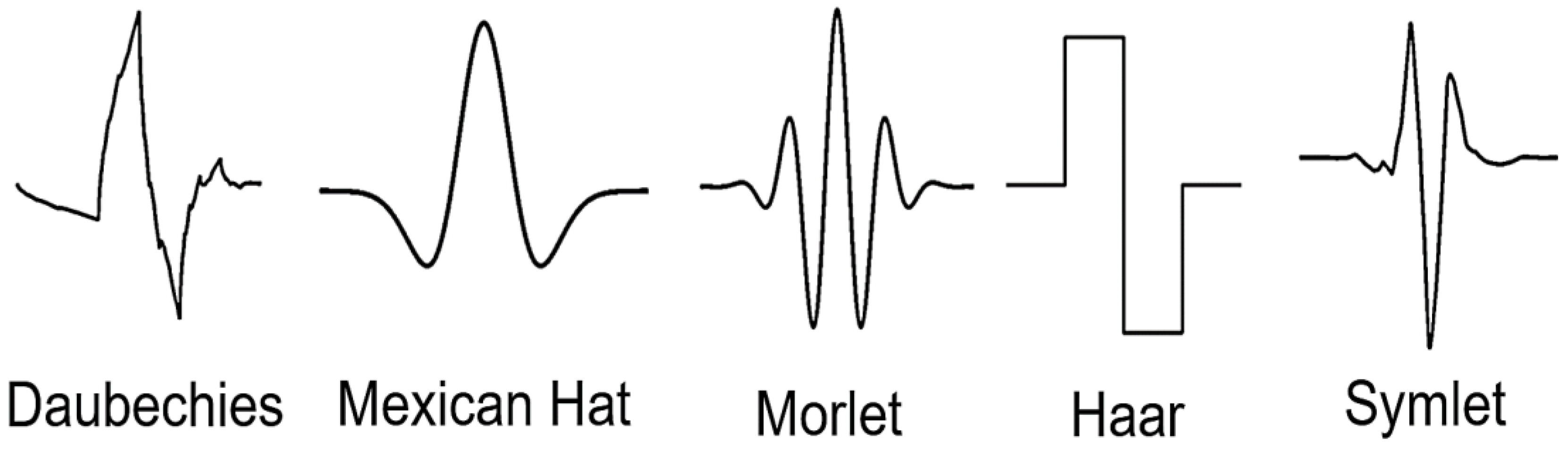
There are main transform functions used in wavelet transformations, and the wavelet family used for the wavelet transform generally consists of the main wavelet function, as well as its scaled and shifted variants. The main wavelet function takes the name of a wavelet family, while the scaled and shifted variants are used to analyze signals with shifted spatial and frequency scales. These main functions are chosen according to specific properties and application requirements, such as computational cost and compatibility with continuous or stationary signals in applications. There are several main functions used in the wavelet transform application, and their basic waveforms are provided in Figure 8.
In this electronic power application, the Haar wavelet function is adapted to design the inverter-switching scheme. The highlighted advantages of the Haar wavelet function are its low computational burden and its efficiency in identifying components in specific frequency and time ranges, which are important for calculating the optimal switching signal to be applied to the switching elements. The Haar wavelet function is used to model the on–off signals of the gate pulses that drive the semiconductor elements in the inverter circuit. The opening signal is represented by the Haar function, and the optimal switching signals are obtained as a result of this computation in which the appropriate scaling function controls the pulse duration and position of the driving signals. Wavelet pulse width modulation (WPWM) is based on non-uniform repetitive sampling and the reconstruction of a reference modulated signal. Functions based on sampling are produced as an expansion of the scaling function , and functions based on synthesis are produced as an extension of the synthesis scaling function ,
Here, j = 1,2,3,… and refers to the Haar scaling function. is as follows:
Using both and , the resulting continuous time function can be determined in detail as follows:
In this equation, j, k ∈ Z, where Z is the set of integers.
In the flow chart in Figure 9, td1 and td2 are the time in the sample group, Tm is the period of the sine wave, and D is the duty period. The time intervals td1 and td2 of each sample group are calculated once the parameters Tm, j0, and D have been determined. The time points in each sample group can provide the driving signals needed to power the semiconductor switches, which can then be combined into two unipolar controlled signals W1 and W2, and these two signals form the core of the WPWM switching algorithm. These two signals alone are not adequate to directly drive the switches of a single-phase three-level inverter and, therefore, some modifications in the switching scheme are needed. Among these other signals is the P1 pulse signal, which has twice the frequency of the reference sine wave and half-cycle symmetry. The output voltage level distribution can be changed by adjusting the pulse width.
Another additional signal is using the same frequency as the reference sine wave, while the C1 pulse is a square signal. Afterwards, using the unique logic relationship between W1, W2, P1, and C1, as provided in Equations (21)–(23), the control signals for the semiconductor switches S1 to S6 of the WPWM inverter application have been effectively produced.
The WPWM control algorithm schematic for a single-phase, three-level inverter with logic gates for the switching signals is shown in Figure 10 and is based on the logical equations that were produced.
The time-dependent waveforms of the W1, W2, P1, and C1 signals applied to the circuit diagram consisting of logic gates obtained as a result of the application of the WPWM algorithm and the raw output voltage generated from the inverter output before the LC filter are scaled relative to each other are provided in Figure 11.
Figure 12 shows the simulation results of the W1 and W2 signal waveforms, which are produced by the WPWM algorithm and contain the percentages of duty periods applied to the logical switching scheme.
Figure 13 shows the simulation results of switching signals obtained by using WPWM signals W1 and W2 and pulse signals P1 and C1 to the logic-switching scheme of a three-level WPWM inverter.
With the switching signals obtained as a result of the WPWM algorithm, an aircraft power system is simulated to supply an RL-type load. The parameters of the RL load used in the simulation of the designed system are R = 10 Ω and L = 0.1 mH, respectively. A lithium battery with a nominal charge voltage of 28 VDC and an output voltage of 26.4 VDC is simulated as the power source of the integrated system designed for aircraft. The simulated lithium battery is modeled to have a nominal capacity of 200 Ah. Figure 14 shows the discharge characteristics of the lithium battery modeled for aircraft power systems at a nominal current and at various discharge currents, including nominal and exponential fields.
An adaptive boost converter structure is used to increase the 28 VDC voltage level obtained from the lithium battery to about 270 VDC. In the adaptive boost converter structure, the reference signal is compared with the signal at the output of the voltage boost converter, and a semiconductor duty cycle is generated with the help of a controller so that the output of the converter provides the reference voltage. PI controller structure is generally preferred in these applications. The main reasons for this preference are easy applicability and higher system stability, and in this study, PI controller structure is preferred as an adaptive voltage-boost converter. The change of lithium battery and adaptive boost converter voltages according to time is provided in Figure 15, and the settling time of the output of the boost converter to steady state is about 0.032 s.
Figure 16 shows the detailed power system of the single-phase three-level pure sine wave static WPWM aircraft-inverter system with a lithium–ion battery and adaptive voltage boost converter, as simulated in this work.
The power system shown in the figure is energized by a lithium battery. There are certain measurement points belonging to the system created and possible undesirable situations are prevented with the measurements made from these points. In this study, Vb represents the boost converter output voltage and VL represents the load voltage. With these measurement points, safety is ensured by disconnecting the battery pack from the circuit in case of possible undesired situations. Simulations of the designed power system were conducted in the MATLAB/Simulink environment. The performance results of the implemented WPWM applications are compared with the sinusoidal pulse width modulation (SPWM) switching technique frequently used in the literature. The performance results of the study are compared with multi-level SPWM bipolar and SPWM unipolar inverter-switching techniques [50].
Using the proposed MEA power-system structure, the comparative waveforms of load voltage and current obtained using different switching approaches are provided in Figure 17 and Figure 18, respectively.
To analyze the performance of the obtained load voltages and currents in detail in terms of performance, THD values of the related signals were calculated. THD is a measure of the harmonic components generated during energy conversion in electronic power systems and provides important insights into the performance of the overall system [51]. It is one of the key parameters that should be improved as a priority in the design process of electronic power systems. A low THD indicates that the designed electronic power systems have higher performance, high efficiency, and stability. Equations for the calculation of THD of voltage and current values are provided in Equations (24) and (25), respectively.
The THD values of the load voltages and currents of the simulated aircraft inverter system are shown in Figure 19.
As a result of the comparison of the obtained THD parameters, in terms of load voltage, it was calculated as 2.642% for SPWM-Bipolar, 2.546% for SPWM-Unipolar, and 1.945% for the WPWM method. In the THD comparison in terms of load currents, it is calculated as 2.509% for SPWM-Bipolar, 2.297% for SPWM-Unipolar, and 1.919% for the WPWM method. In the power system’s design implementation of this aircraft-inverter system, the unipolar method performed slightly better than the bipolar method in terms of THD value regarding SPWM methods. The WPWM method described in this study significantly improved the performance by reducing the THD value by 27% compared to the unipolar SPWM approach.
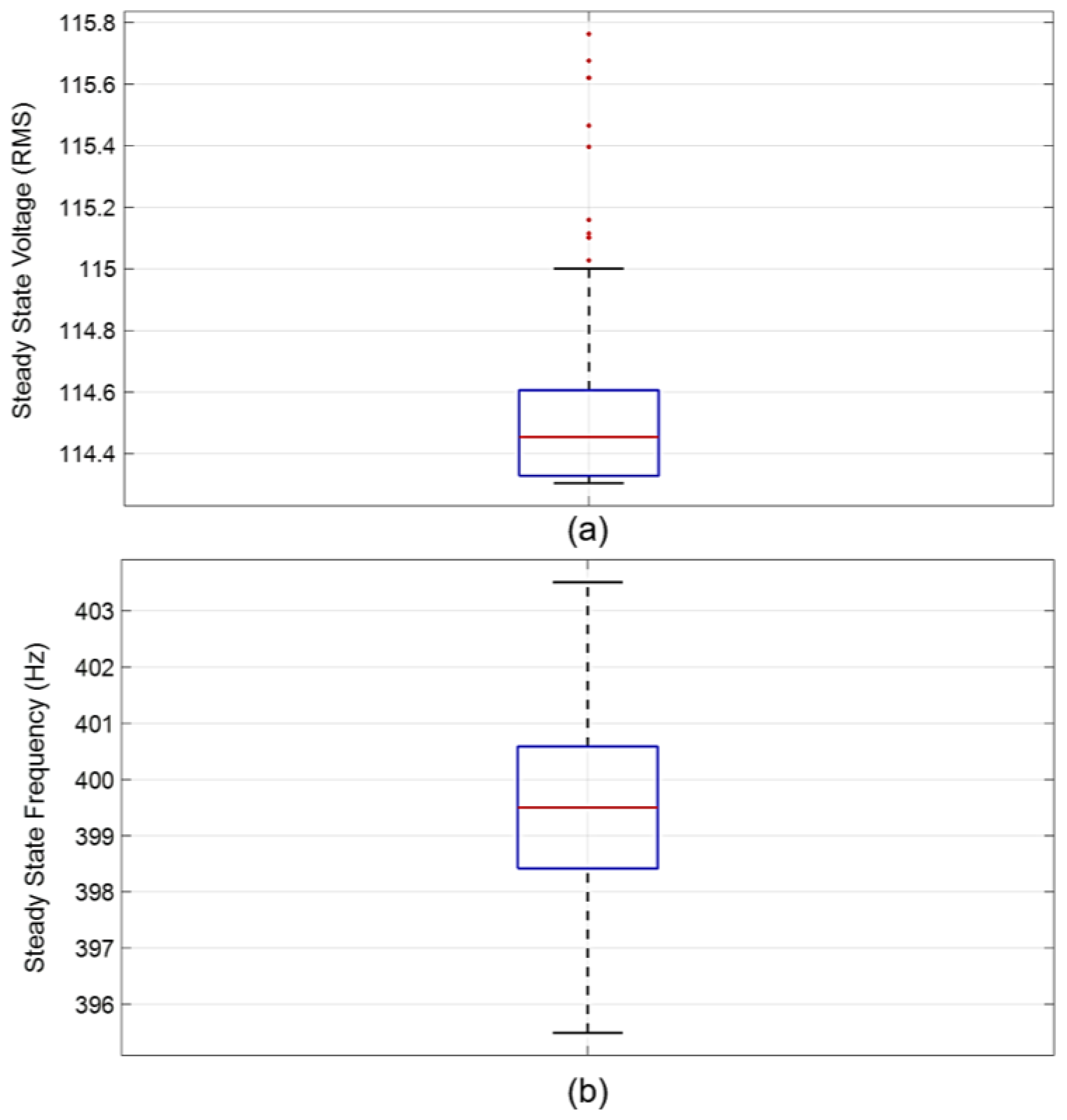
Figure 20 presents the statistical distribution of output voltage samples, meeting the criteria for steady-state RMS voltage (108 to 118 VDC) and steady-state output frequency (393 to 407 Hz), in accordance with the MIL-STD-704F standard, when examining the parameters of the modeled aircraft-inverter system.
Upon examination of the time-dependent statistical output data of the steady-state results from the modeled MEA power system based on the WPWM inverter, it becomes evident that the system achieves high accuracy in providing reference values (115 VAC and 400 Hz) once it reaches a steady state.
WPWM applications can offer different advantages in various power systems, not only for aircraft power systems. As supported by the results of this study, when used in inverter systems, it can significantly reduce THD and increase the size of key components. When used in motor drives, it can improve efficiency and performance by controlling the speed and torque of electric motors. In renewable energy systems, especially in solar and wind energy converters, it can improve power-conversion efficiency and reduce harmonic distortion in the generated power. In power systems, it can be used in grid-connected inverters, power-conditioning units, and active power filters to improve power quality, reduce harmonics, and increase system stability. Also widely preferred in industrial applications, adjustable speed drives are suitable for a variety of applications that require high-quality power conversion, such as uninterruptible power supplies (UPS) and industrial automation systems.
5. Conclusions
In this study, a power system designed to enhance the performance of more electric aircraft is presented. The WPWM method was integrated with the inverter system of the proposed comprehensive MEA power system, and the system’s performance outcomes were examined in detail. The energy demand of the designed power system was provided and modeled using lithium–ion battery structures instead of Nicd battery structures, which are frequently used in traditional applications in aircraft. In this study, which was conducted in the field of aircraft power electronics, information was provided about lithium battery technologies, which are expected to be used on the path to more electric aircraft and, eventually, fully electric aircraft, and whose use in this field is increasing day by day. Also, the load-dependent discharge characteristic of the battery system was obtained. When designing the MEA power system, details on power and frequency compatibility were provided during semiconductor selection. Criteria-based semiconductor switch selection, switching loss, and efficiency calculations were performed to provide compatibility with the specified power system. The efficiency of the modeled single-phase three-level pure sine wave static aircraft inverter is calculated as 93.661%. To reduce the output harmonic level, LC filter design for the single-phase three-level pure sine wave static aircraft-inverter system is performed, and parameters are obtained. In the proposed MEA power system, an adaptive boost-converter structure was developed to increase the 28 VDC voltage from the lithium–ion battery pack to 270 VDC, and it was determined that the system reached a steady state in 0.032 s. The investigation has led to the design and detailing of a power system that will meet aircraft electric power characteristic standards while enabling the aircraft avionics, ventilation, and navigation systems to operate more efficiently than traditional power systems. The increased output voltage obtained from the boost converter is applied to the multilevel WPWM inverter and filter structure to perform the related MEA power system. Detailed performance results of the WPWM-based MEA power system are compared with the results of SPWM Bipolar and Unipolar switching techniques, which are frequently used in single-phase inverter-design processes. The THD values for load voltages and currents of the MEA system were compared, resulting in 2.642% for SPWM-Bipolar, 2.546% for SPWM-Unipolar, and 1.945% for the WPWM method for load voltages. In terms of load currents, the THD values were calculated as 2.509% for SPWM-Bipolar, 2.297% for SPWM-Unipolar, and 1.919% for the WPWM method. According to the comparison results, it is determined that the WPWM algorithm, the focus of this study, reduces the THD value by about 27% more than the other methods, resulting in a THD value below 2% for both load current and load voltage in the aircraft-inverter system that was realized with the WPWM method. An analysis of the time-dependent statistical output data of the steady-state results obtained from the modeled WPWM-based MEA power system shows that the system achieves significant performance in providing the reference values (115 VAC and 400 Hz) when it reaches a steady state. Based on the findings of this research, the proposed WPWM-based MEA power system provides improved performance for MEA applications while at the same time complying with aircraft electrical power specification standards.
Author Contributions
N.C.: Conceptualization, Data curation, Formal analysis, Investigation, Methodology, Visualization, Writing—original draft, Writing—review and editing. A.G.P.: Formal analysis, Investigation, Writing—review and editing, G.S.: Investigation, Formal analysis, Supervision, Writing—review & editing. All authors have read and agreed to the published version of the manuscript.
Funding
This research received no external funding.
Data Availability Statement
The raw data supporting the conclusions of this article will be made available by the authors on request.
Conflicts of Interest
The authors declare that they have no known competing financial interests or personal relationships that could have appeared to influence the work reported in this paper.
Nomenclature
| MOSFET conduction loss | |
| Diode conduction loss | |
| Effective value of load current | |
| Total resistance between drain-source in a semiconductor switch | |
| Diode threshold voltage | |
| Diode average current | |
| Effective value of diode current | |
| MOSFET switching loss | |
| Diode switching loss | |
| The energy of the MOSFET during on | |
| The energy of the MOSFET during off | |
| Load current | |
| Input voltage | |
| MOSFET on time | |
| MOSFET off time | |
| Switching frequency | |
| Voltage of the diode at off | |
| Number of semiconductor switches in the circuit | |
| Input power | |
| Output power | |
| Input current |
References
- Thonemann, N.; Pierrat, E.; Dudka, K.M.; Saavedra-Rubio, K.; Dragsdahl, A.L.S.T.; Laurent, A. Towards sustainable regional aviation: Environmental potential of hybrid-electric aircraft and alternative fuels. Sustain. Prod. Consum. 2024, 45, 371–385. [Google Scholar] [CrossRef]
- Deja, J.; Dayyani, I.; Nair, V.; Skote, M. More Electric Aircraft Conversion to All-Electric During Ground Operations: Battery Powered Landing Gear Drive System. IEEE Trans. Transp. Electrif. 2023, 10, 744–759. [Google Scholar] [CrossRef]
- Gimenez, F.R.; Mady, C.E.K.; Henriques, I.B. Assessment of different more-electric and hybrid-electric configurations for long-range multi-engine aircraft. J. Clean. Prod. 2023, 392, 136171. [Google Scholar] [CrossRef]
- Barzkar, A.; Ghassemi, M. Components of electrical power systems in more and all-electric aircraft: A review. IEEE Trans. Transp. Electrif. 2022, 8, 4037–4053. [Google Scholar] [CrossRef]
- Dorn-Gomba, L.; Ramoul, J.; Reimers, J.; Emadi, A. Power electronic converters in electric aircraft: Current status, challenges, and emerging technologies. IEEE Trans. Transp. Electrif. 2020, 6, 1648–1664. [Google Scholar] [CrossRef]
- Huang, Z.; Yang, T.; Giangrande, P.; Galea, M.; Wheeler, P. Technical review of dual inverter topologies for more electric aircraft applications. IEEE Trans. Transp. Electrif. 2021, 8, 1966–1980. [Google Scholar] [CrossRef]
- Ebersberger, J.; Hagedorn, M.; Lorenz, M.; Mertens, A. Potentials and comparison of inverter topologies for future all-electric aircraft propulsion. IEEE J. Emerg. Sel. Top. Power Electron. 2022, 10, 5264–5279. [Google Scholar] [CrossRef]
- Liaw, C.M.; Jhou, P.H.; Yang, C.W. Switched-Reluctance Motor Drive for More Electric Aircraft with Energy Storage Buffer. IEEE Trans. Aerosp. Electron. Syst. 2023, 59, 7423–7439. [Google Scholar] [CrossRef]
- Saini, H.; Sandeep, N.; Jakhar, A.; Verma, A.K. Design and Implementation of Five Level Inverter Topology for More Electric Aircraft Application. In Proceedings of the IEEE International Conference on Power Electronics, Smart Grid, and Renewable Energy (PESGRE), Trivandrum, India, 2–5 January 2022; pp. 1–6. [Google Scholar]
- Diao, F.; Du, X.; Ma, Z.; Wu, Y.; Guo, F.; Li, Y.; Zhao, Y. A Megawatt-Scale Si/SiC Hybrid Multilevel Inverter for Electric Aircraft Propulsion Applications. IEEE J. Emerg. Sel. Top. Power Electron. 2023, 11, 4095–4107. [Google Scholar] [CrossRef]
- Liu, Y.; Mo, D.; Nalianda, D.; Li, Y.; Roumeliotis, I. Review of more electric engines for civil aircraft. Int. J. Aeronaut. Space Sci. 2022, 23, 784–793. [Google Scholar] [CrossRef]
- Wheeler, P.; Bozhko, S. The more electric aircraft: Technology and challenges. IEEE Electrif. Mag. 2014, 2, 6–12. [Google Scholar] [CrossRef]
- Rajashekara, K. More electric aircraft trends [Technology Leaders]. IEEE Electrif. Mag. 2014, 2, 4–39. [Google Scholar] [CrossRef]
- Ni, K.; Liu, Y.; Mei, Z.; Wu, T.; Hu, Y.; Wen, H.; Wang, Y. Electrical and electronic technologies in more-electric aircraft: A review. IEEE Access 2019, 7, 76145–76166. [Google Scholar] [CrossRef]
- Perdikakis, W.; Scott, M.; Yost, K.J.; Miller, C.; Scofield, J. Conducted EMI Modeling and Evaluation of Si and SiC devices on Aerospace Machine. In Proceedings of the IEEE International Electric Machines & Drives Conference (IEMDC), Hartford, CT, USA, 17–20 May 2021; pp. 1–6. [Google Scholar]
- Cao, W.; Mecrow, B.C.; Atkinson, G.J.; Bennett, J.W.; Atkinson, D.J. Overview of electric motor technologies used for more electric aircraft (MEA). IEEE Trans. Ind. Electron. 2011, 59, 3523–3531. [Google Scholar]
- Patnaik, B.; Kumar, S.; Gawre, S. Recent advances in converters and storage technologies for more electric aircrafts: A review. IEEE J. Miniaturization Air Space Syst. 2022, 3, 78–87. [Google Scholar] [CrossRef]
- Alle, N.; Hiremath, S.S.; Makaram, S.; Subramaniam, K.; Talukdar, A. Review on electro hydrostatic actuator for flight control. Int. J. Fluid Power 2016, 17, 125–145. [Google Scholar] [CrossRef]
- Zhang, Q.; Norman, P.; Burt, G. Design rules to establish a credible More-Electric Engine baseline power architecture concept. IET Electr. Syst. Transp. 2023, 13, e12076. [Google Scholar] [CrossRef]
- Chen, J.; Wang, C.; Chen, J. Investigation on the selection of electric power system architecture for future more electric aircraft. IEEE Trans. Transp. Electrif. 2018, 4, 563–576. [Google Scholar] [CrossRef]
- Fan, Z.; Zhao, Z.; Liu, Z. Automatic management of electrical loads in more electric aircraft. Aircr. Eng. Aerosp. Technol. 2023, 95, 14–25. [Google Scholar] [CrossRef]
- Wang, C.; Yang, T.; Hussaini, H.; Bozhko, S. Using DC–DC Converters as Active Harmonic Suppression Device for More Electric Aircraft Applications. IEEE Trans. Ind. Electron. 2021, 69, 6508–6518. [Google Scholar] [CrossRef]
- Barzkar, A.; Ghassemi, M. Electric power systems in more and all electric aircraft: A review. IEEE Access 2020, 8, 169314–169332. [Google Scholar] [CrossRef]
- Lee, D.S.; Fahey, D.W.; Skowron, A.; Allen, M.R.; Burkhardt, U.; Chen, Q.; Wilcox, L.J. The contribution of global aviation to anthropogenic climate forcing for 2000 to 2018. Atmos. Environ. 2021, 244, 117834. [Google Scholar] [CrossRef]
- Abdel-Fadil, R.; Eid, A.; Abdel-Salam, M. Electrical distribution power systems of modern civil aircrafts. In Proceedings of the 2nd International Conference on Energy Systems and Technologies, Cairo, Egypt, 18–21 February 2013; Springer: Berlin/Heidelberg, Germany, 2013; pp. 201–210. [Google Scholar]
- Salem, K.A.; Palaia, G.; Quarta, A.A. Review of hybrid-electric aircraft technologies and designs: Critical analysis and novel solutions. Prog. Aerosp. Sci. 2023, 141, 100924. [Google Scholar] [CrossRef]
- Itani, K.; De Bernardinis, A. Review on New-Generation Batteries Technologies: Trends and Future Directions. Energies 2023, 16, 7530. [Google Scholar] [CrossRef]
- Mahmud, S.; Rahman, M.; Kamruzzaman, M.; Ali, M.O.; Emon, M.S.A.; Khatun, H.; Ali, M.R. Recent advances in lithium-ion battery materials for improved electrochemical performance: A review. Results Eng. 2022, 15, 100472. [Google Scholar] [CrossRef]
- Wileman, A.J.; Aslam, S.; Perinpanayagam, S. A road map for reliable power electronics for more electric aircraft. Prog. Aerosp. Sci. 2021, 127, 100739. [Google Scholar] [CrossRef]
- Aircraft Electric Power Characteristics, MIL-STD-704F, Mar 2004. Available online: http://everyspec.com/MIL-STD/MIL-STD-0700-0799/MIL-STD-704F_1083/ (accessed on 23 April 2024).
- Clarke, M.; Alonso, J.J. Lithium–ion battery modeling for aerospace applications. J. Aircr. 2021, 58, 1323–1335. [Google Scholar] [CrossRef]
- Nawawi, A.; Tong, C.F.; Yin, S.; Sakanova, A.; Liu, Y.; Liu, Y.; Gupta, A.K. Design and demonstration of high-power density inverter for aircraft applications. IEEE Trans. Ind. Appl. 2016, 53, 1168–1176. [Google Scholar] [CrossRef]
- Mao, H.; Yang, X.; Chen, Z.; Wang, Z. A hysteresis current controller for single-phase three-level voltage source inverters. IEEE Trans. Power Electron. 2012, 27, 3330–3339. [Google Scholar] [CrossRef]
- Zheng, C.F.; Zhang, B.; Qiu, D.Y.; Zhang, X.H.; Xiao, L.M. Wavelet PWM technique for single-phase three-level inverters. J. Power Electron. 2015, 15, 1517–1523. [Google Scholar] [CrossRef]
- Ayub, M.A.; Aziz, S.; Liu, Y.; Peng, J.; Yin, J. Design and Control of Novel Single-Phase Multilevel Voltage Inverter Using MPC Controller. Sustainability 2023, 15, 860. [Google Scholar] [CrossRef]
- Yang, Y.; Xiao, Y.; Fan, M.; Wang, K.; Zhang, X.; Hu, J.; Rodriguez, J. A novel continuous control set model predictive control for LC-filtered three-phase four-wire three-level voltage-source inverter. IEEE Trans. Power Electron. 2023, 38, 4572–4584. [Google Scholar] [CrossRef]
- Ali, M.; Iqbal, A.; Khalid, M. A review on recent advances in matrix converter technology: Topologies, control, applications, and future prospects. Int. J. Energy Res. 2023, 2023, 6619262. [Google Scholar] [CrossRef]
- Safak, B. Design and Application of 115 V 400 Hz Inverter for Aircraft Systems. Master’s Thesis, Eskisehir Osmangazi University Institute of Science and Technology, Eskisehir, Turkey, 2019. [Google Scholar]
- Qian, Q.; Wu, C.; Zhang, L.; Xie, S.; Guo, S. Improved Repetitive Control with Enhanced Active Damping Method for 400 Hz Inverter. In Proceedings of the IECON 2023-49th Annual Conference of the IEEE Industrial Electronics Society, Singapore, 16–19 October 2023; pp. 1–6. [Google Scholar]
- Kim, H.S.; Sul, S.K. A novel filter design for output LC filters of PWM inverters. J. Power Electron. 2011, 11, 74–81. [Google Scholar] [CrossRef]
- Kim, Y.J.; Kim, H. Optimal design of LCL filter in grid-connected inverters. IET Power Electron. 2019, 12, 1774–1782. [Google Scholar] [CrossRef]
- Thavaratnam, T.; Li, C.; Xu, D. Switching frequency selection for aerospace power converter system considering the design of output LC filter inductor optimizing weight and power loss. In Proceedings of the IEEE Electrical Power and Energy Conference (EPEC), Ottawa, ON, Canada, 12–14 October 2016; pp. 1–5. [Google Scholar]
- Rafin, S.S.H.; Ahmed, R.; Haque, M.A.; Hossain, M.K.; Haque, M.A.; Mohammed, O.A. Power Electronics Revolutionized: A Comprehensive Analysis of Emerging Wide and Ultrawide Bandgap Devices. Micromachines 2023, 14, 2045. [Google Scholar] [CrossRef] [PubMed]
- Prado, E.O.; Bolsi, P.C.; Sartori, H.C.; Pinheiro, J.R. An overview about Si, Superjunction, SiC and GaN power MOSFET technologies in power electronics applications. Energies 2022, 15, 5244. [Google Scholar] [CrossRef]
- Chen, Z.; Huang, A.Q. Extreme high efficiency enabled by silicon carbide (SiC) power devices. Mater. Sci. Semicond. Process. 2024, 172, 108052. [Google Scholar] [CrossRef]
- Guo, T.; Zhang, T.; Lim, E.; Lopez-Benitez, M.; Ma, F.; Yu, L. A review of wavelet analysis and its applications: Challenges and opportunities. IEEE Access 2022, 10, 58869–58903. [Google Scholar] [CrossRef]
- Akhil Vinayak, B.; Anjali Anand, K.; Jagadanand, G. Wavelet-based real-time stator fault detection of inverter-fed induction motor. IET Electr. Power Appl. 2020, 14, 82–90. [Google Scholar] [CrossRef]
- Liu, C.; Zhuo, F.; Wang, F. Fault diagnosis of commutation failure using wavelet transform and wavelet neural network in HVDC transmission system. IEEE Trans. Instrum. Meas. 2021, 70, 1–8. [Google Scholar] [CrossRef]
- Saleh, S.A.; Rahman, M.A. Experimental performances of the single-phase wavelet-modulated inverter. IEEE Trans. Power Electron. 2011, 26, 2650–2661. [Google Scholar] [CrossRef]
- Singh, S.; Gorla, N.B.Y.; Jayaraman, K.; Pou, J. Analysis and Mitigation of Common-Mode Noise with Different Modulation Strategies in SiC-Fed Three-Phase Brushless DC Motor Drive. IEEE J. Emerg. Sel. Top. Power Electron. 2023, 12, 663–674. [Google Scholar] [CrossRef]
- Liu, Z.; Li, C.; Yang, Y.; Zhang, W.; Shen, X.; Wu, X.; Qin, H. An optimal predictive control method for three-level inverter with low switching losses under target current THD. Energy Rep. 2023, 9, 368–378. [Google Scholar] [CrossRef]
Figure 1.
System power distribution for civil aircraft (a) conventional aircraft (b) MEA aircraft.

Figure 2.
Power distribution system of MEA.

Figure 3.
Flowchart of the power system design process.

Figure 4.
Single phase three-level pure sine wave static inverter circuit.

Figure 5.
LC filter circuit.

Figure 6.
Radar chart comparison of Si, GaN, and SiC properties.

Figure 7.
Application fields of semiconductor switches according to frequency and power.

Figure 8.
Main wavelet functions.

Figure 9.
Flowchart for WPWM application.

Figure 10.
Logic switching scheme of three-level WPWM inverter.

Figure 11.
Waveform of W1, W2, P1, C1 and Uab.

Figure 12.
Duty cycle percentage of W1 and W2 (D = 30, fm = 400 Hz).

Figure 13.
Semiconductor switching signals of WPWM algorithm: (a) ; (b) ; (c) .

Figure 14.
Discharge characteristics: (a) Nominal current with areas; (b) Various discharge currents.
Figure 14.
Discharge characteristics: (a) Nominal current with areas; (b) Various discharge currents.

Figure 15.
Boost converter and battery voltages.

Figure 16.
Modeled aircraft power system.

Figure 17.
Load voltage change according to switching methodologies.

Figure 18.
Load current change according to switching methodologies.

Figure 19.
THD according to switching methodologies: (a) voltage; (b) current.

Figure 20.
Steady-state characteristics: (a) output voltage; (b) frequency.


Table 1.
Differences between conventional aircraft and MEA [20].
Table 1.
Differences between conventional aircraft and MEA [20].
| Conventional Aircraft | MEA |
|---|---|
| Conventional motor generates hydraulic, pneumatic, and electric power; pneumatic actuation | Parallel architectures connect thermal and electrical engines to propellers with mechanical shafts (hybrid director), electric start |
| Conventional auxiliary power unit (APU) generates hydraulic, pneumatic, and electrical power | Electric APU generates electric power only |
| Several power electronic converters | More power electronics converters |
| Hydraulic and pneumatic actuators | Electrically supported hydraulic and pneumatic actuators |
| Mechanical brakes | Mechanical and electric brakes |
| AC circuit breakers and low-voltage DC breakers | Solid state power contactors |
| The battery is only used in emergencies and for APU initialization | Used in all flight phases |
| Conventional motor generates hydraulic, pneumatic, and electric power; pneumatic actuation | Parallel architectures connect thermal and electrical engines to propellers with mechanical shafts (hybrid director), electric start |
| Conventional auxiliary power unit (APU) generates hydraulic, pneumatic, and electrical power | Electric APU generates electric power only |
Table 2.
Aircraft electrical power characteristics standard (MIL-STD-704F).
| Steady-State Characteristics | Limitations |
|---|---|
| Steady-State Voltage | 108.0–118.0 Volts RMS |
| Voltage Unbalance | Maximum 3.0 Volts RMS |
| Voltage Modulation | Maximum 2.5 Volts RMS |
| Phase Angle Difference | 116°–124° |
| Harmonic Factor | Maximum 0.05 |
| DC Component | ±0.10 Volts |
| Steady-State Frequency | 393–407 Hz |
| Frequency Modulation | 4 Hz |
| Peak Voltage Value | ±271.8 Volts |
Table 3.
Three-level inverter output voltage and switch states.
| States | Switches in on State | Switches in the off State | |
|---|---|---|---|
| 1 | |||
| 2 | |||
| 3 | |||
| 4 | |||
| 5 | |||
| 6 |
Table 4.
Parameters of single-phase three-level pure sine wave static aircraft inverter.
| Output power () | 5 kW |
| Output voltage () | 115 V(RMS) |
| Output frequency () | 400 Hz |
| Duty cycle (D) | 0.5 |
| Switching frequency () | 20 kHz |
Table 5.
Semiconductor Element Parameters.
| MOSFET internal resistance () | 25 mΩ |
| MOSFET conduction energy () | 1.4 mJ |
| MOSFET cut-off energy () | 0.3 mJ |
| Diode threshold voltage () | 0.7 V |
| Diode internal resistance () | 0.1 Ω |
| Diode capacity () | 15 pF |
Disclaimer/Publisher’s Note: The statements, opinions and data contained in all publications are solely those of the individual author(s) and contributor(s) and not of MDPI and/or the editor(s). MDPI and/or the editor(s) disclaim responsibility for any injury to people or property resulting from any ideas, methods, instructions or products referred to in the content. |
© 2024 by the authors. Licensee MDPI, Basel, Switzerland. This article is an open access article distributed under the terms and conditions of the Creative Commons Attribution (CC BY) license (https://creativecommons.org/licenses/by/4.0/).
Share and Cite
MDPI and ACS Style
Catalbas, N.; Pakfiliz, A.G.; Soysal, G. Multilevel Aircraft-Inverter Design Based on Wavelet PWM for More Electric Aircraft. Energies 2024, 17, 2054. https://doi.org/10.3390/en17092054
AMA Style
Catalbas N, Pakfiliz AG, Soysal G. Multilevel Aircraft-Inverter Design Based on Wavelet PWM for More Electric Aircraft. Energies. 2024; 17(9):2054. https://doi.org/10.3390/en17092054
Chicago/Turabian StyleCatalbas, Nurbanu, Ahmet Gungor Pakfiliz, and Gokhan Soysal. 2024. "Multilevel Aircraft-Inverter Design Based on Wavelet PWM for More Electric Aircraft" Energies 17, no. 9: 2054. https://doi.org/10.3390/en17092054
Note that from the first issue of 2016, this journal uses article numbers instead of page numbers. See further details here.