
Carbon-Based Materials for Energy Storage Devices: Types and Characterization Techniques


Abstract
:1. Introduction
1.1. History
1.2. Principle of Operation for EDLC
1.3. Components of the Supercapacitors: Active Electrode Materials, Electrolytes, Separator, and Current Collectors
- (i)
- Active Electrode Materials:
- (1)
- Onion-Like Carbons (OLCs)
- (2)
- Carbon Nanotubes (CNTs)
- (3)
- Graphene
- (4)
- Carbide-Derived Carbons (CDCs)
- (5)
- Activated Carbons (ACs)
- (6)
- Templated carbons
- a.
- Ion Sieving
- b.
- Ion Desolvation
- c.
- Pore Saturation
- d.
- Distortion
- (ii)
- Electrolytes:
- (iii)
- Current collectors:
- (iv)
- Separators:
2. Proposed Strategies for Higher Performance in Supercapacitors: (Nano)Structuring, Electrolyte Composition, Pseudocapacitance, and Hybrid and Composite Electrodes
- (i)
- Nanostructuration
- (ii)
- Electrolyte Composition
- (iii)
- Pseudocapacitance
- (iv)
- Hybrid Electrodes
- (v)
- Nanocomposite electrodes
3. Diagnostic Tools for Electrode Materials in Energy Storage
- (i)
- Cyclic Voltammetry (CV)
- (ii)
- Galvanostatic Charge-Discharge method (GCD)
- (iii)
- Electrochemical Impedance Spectroscopy (EIS)
- (iv)
- Electrochemical Quartz Crystal Microbalance (EQCM)
- (v)
- ac-electrogravimetry
- (vi)
- Nuclear magnetic resonance spectroscopy (NMR)
- (vii)
- Computer Simulations
4. Advantages and Challenges of Main Techniques Used in Energy Storage
5. Summary and Perspectives
Author Contributions
Funding
Data Availability Statement
Conflicts of Interest
References
- Kabeyi, M.J.B.; Olanrewaju, O.A. Sustainable Energy Transition for Renewable and Low Carbon Grid Electricity Generation and Supply. Front. Energy Res. 2022, 9, 1032. [Google Scholar] [CrossRef]
- Simon, P.; Gogotsi, Y. Materials for electrochemical capacitors. Nat Mater 2008, 7, 845–854. [Google Scholar] [CrossRef] [PubMed]
- Shao, H.; Wu, Y.-C.; Lin, Z.; Taberna, P.-L.; Simon, P. Nanoporous carbon for electrochemical capacitive energy storage. Chem. Soc. Rev. 2020, 49, 3005–3039. [Google Scholar] [CrossRef]
- Escobar-Teran, F.; Perrot, H.; Sel, O. Ion Dynamics at the Carbon Electrode/Electrolyte Interface: Influence of Carbon Nanotubes Types. Materials 2022, 15, 1867. [Google Scholar] [CrossRef]
- Escobar-Teran, F.; Perrot, H.; Sel, O. Single Wall Carbon Nanotubes/Polypyrrole Composite Thin Film Electrodes: Investigation of Interfacial Ion Exchange Behavior. J. Compos. Sci. 2021, 5, 25. [Google Scholar] [CrossRef]
- Banerjee, S.; De, B.; Sinha, P.; Cherusseri, J.; Kar, K.K. Applications of Supercapacitors. In Handbook of Nanocomposite Supercapacitor Materials I: Characteristics; Kar, K.K., Ed.; Springer International Publishing: Cham, Switzerland, 2020; pp. 341–350. [Google Scholar] [CrossRef]
- Devi, S.B.; Vignesh, V.; Kumar, P.V.; Oh, M.S.; Navamathavan, R. Chapter 19—Transport supercapacitors. In Smart Supercapacitors; Hussain, C.M., Ahamed, M.B., Eds.; Elsevier: Amsterdam, The Netherlands, 2023; pp. 503–534. [Google Scholar] [CrossRef]
- Evanko, B.; Boettcher, S.W.; Yoo, S.J.; Stucky, G.D. Redox-Enhanced Electrochemical Capacitors: Status, Opportunity, and Best Practices for Performance Evaluation. ACS Energy Lett. 2017, 2, 2581–2590. [Google Scholar] [CrossRef]
- Kim, B.K.; Sy, S.; Yu, A.; Zhang, J. Electrochemical Supercapacitors for Energy Storage and Conversion. In Handbook of Clean Energy Systems; John Wiley & Sons, Ltd.: Hoboken, NJ, USA, 2015. [Google Scholar] [CrossRef]
- Zhai, Z.; Zhang, L.; Du, T.; Ren, B.; Xu, Y.; Wang, S.; Miao, J.; Liu, Z. A review of carbon materials for supercapacitors. Mater. Des. 2022, 221, 111017. [Google Scholar] [CrossRef]
- Lin, R. Formulation of Electrolytes Based on Ionic Liquids for Supercapacitor Applications. Ph. D. Thesis, Sciences de la Matiére, Université de Toulouse, Toulouse, France, 2012. [Google Scholar]
- Benhaddad, L. Elaboration et caractérisation de poudres nanostructurées de MnO2 et de polypyrrole: Application comme matériaux d’électrodes dans des dispositifs de stockage de l’énergie. Ph.D. Thesis, Chimie Physique et Chimie Analytique de Paris-Centre, Université Pierre et Marie Curie, Paris, France, 2014; p. 217. [Google Scholar]
- Shiferaw, T. Investigation of the Interfaces of Solid Electrolyte Based Supercapacitors and Batteries. Ph.D. Thesis, Technischen Fakultät der Christian-Albrechts, Universität zu Kiel, Kiel, Germany, 2008. [Google Scholar]
- Mohd Abdah, M.A.A.; Azman, N.H.N.; Kulandaivalu, S.; Sulaiman, Y. Review of the use of transition-metal-oxide and conducting polymer-based fibres for high-performance supercapacitors. Mater. Des. 2020, 186, 108199. [Google Scholar] [CrossRef]
- Olabi, A.G.; Abbas, Q.; Abdelkareem, M.A.; Alami, A.H.; Mirzaeian, M.; Sayed, E.T. Carbon-Based Materials for Supercapacitors: Recent Progress, Challenges and Barriers. Batteries 2023, 9, 19. [Google Scholar] [CrossRef]
- Gao, Q. Optimizing Carbon/Carbon Supercapacitors in Aqueous and Organic Electrolytes. Ph.D. Thesis, Energie, Matériaux, Sciences De la Terre et de l’Univers, Université d’Orleans, Orléans, France, 2013. [Google Scholar]
- Segalini, J. Etude de L’adsorption des Ions dans des Carbones Microporeux; Application aux Supercondensateurs. Ph.D. Thesis, Sciences de la Matiére Université de Toulouse, Toulouse, France, 2012. [Google Scholar]
- Zhang, L.L. Carbon-Based Materials as Supercapacitor Electrodes. Ph.D. Thesis, Department of Chemical and Biomolecular Engineering, National University of Singapore, Singapore, 2010. [Google Scholar]
- Zhang, J.; Zhao, X.S. On the Configuration of Supercapacitors for Maximizing Electrochemical Performance. ChemSusChem 2012, 5, 818–841. [Google Scholar] [CrossRef] [PubMed]
- Simon, P.; Gogotsi, Y. Charge storage mechanism in nanoporous carbons and its consequence for electrical double layer capacitors. Philos. Trans. Ser. A Math. Phys. Eng. Sci. 2010, 368, 3457–3467. [Google Scholar] [CrossRef]
- Chen, T.; Dai, L. Carbon nanomaterials for high-performance supercapacitors. Mater. Today 2013, 16, 272–280. [Google Scholar] [CrossRef]
- Conte, M. Supercapacitors Technical Requirements for New Applications. Fuel Cells 2010, 10, 806–818. [Google Scholar] [CrossRef]
- Roland, G.; Hamid, G. Industrial Production of Double-Layer Capacitors. In Carbons for Electrochemical Energy Storage and Conversion Systems; CRC Press: Boca Raton, FL, USA, 2009; pp. 429–467. [Google Scholar] [CrossRef]
- Lu, W.; Dai, L. Carbon Nanotube Supercapacitors; Mauricio, M.J., Ed.; Carbon Nanotubes; IntechOpen: Rijeka, Croatia, 2010; p. 29. [Google Scholar]
- Béguin, F.; Presser, V.; Balducci, A.; Frackowiak, E. Carbons and Electrolytes for Advanced Supercapacitors. Adv. Mater. 2014, 26, 2219–2251. [Google Scholar] [CrossRef]
- Candelaria, S.L.; Shao, Y.; Zhou, W.; Li, X.; Xiao, J.; Zhang, J.-G.; Wang, Y.; Liu, J.; Li, J.; Cao, G. Nanostructured carbon for energy storage and conversion. Nano Energy 2012, 1, 195–220. [Google Scholar] [CrossRef]
- Davies, A.; Yu, A. Material advancements in supercapacitors: From activated carbon to carbon nanotube and graphene. Can. J. Chem. Eng. 2011, 89, 1342–1357. [Google Scholar] [CrossRef]
- Come, J. Caractérisation Électrochimique de Matériaux à Insertion de Li pour Supercondensateurs Hybrides à Haute Densité D’énergie. Ph.D. Thesis, Sciences et Génie des Matériaux, Université de Toulouse, Toulouse, France, 2012. [Google Scholar]
- Halper, M.S.E.; James, C. Supercapacitors: A Brief Overview; The MITRE Corporation: McLean, VA, USA, 2006. [Google Scholar]
- Simon, P.; Gogotsi, Y. Capacitive Energy Storage in Nanostructured Carbon–Electrolyte Systems. Acc. Chem. Res. 2013, 46, 1094–1103. [Google Scholar] [CrossRef] [PubMed]
- Zhang, L.L.; Zhao, X.S. Carbon-based materials as supercapacitor electrodes. Chem. Soc. Rev. 2009, 38, 2520–2531. [Google Scholar] [CrossRef] [PubMed]
- Kotzabasaki, M.; Sotiropoulos, I.; Charitidis, C.; Sarimveis, H. Machine learning methods for multi-walled carbon nanotubes (MWCNT) genotoxicity prediction. Nanoscale Adv. 2021, 3, 3167–3176. [Google Scholar] [CrossRef] [PubMed]
- Maheswaran, R.; Shanmugavel, B.P. A Critical Review of the Role of Carbon Nanotubes in the Progress of Next-Generation Electronic Applications. J. Electron. Mater. 2022, 51, 2786–2800. [Google Scholar] [CrossRef]
- Yan, J.; Wang, Q.; Wei, T.; Fan, Z. Recent Advances in Design and Fabrication of Electrochemical Supercapacitors with High Energy Densities. Adv. Energy Mater. 2014, 4, 1300816. [Google Scholar] [CrossRef]
- Hu, L.; Hecht, D.S.; Gruener, G. Carbon Nanotube Thin Films: Fabrication, Properties, and Applications. Chem. Rev. 2010, 110, 5790–5844. [Google Scholar] [CrossRef]
- Szabó, A.; Perri, C.; Csató, A.; Giordano, G.; Vuono, D.; Nagy, J.B. Synthesis Methods of Carbon Nanotubes and Related Materials. Materials 2010, 3, 3092–3140. [Google Scholar] [CrossRef]
- Baddour, C.E.; Briens, C.L.; Bordere, S.; Anglerot, D.; Gaillard, P. An investigation of carbon nanotube jet grinding. Chem. Eng. Process. Process Intensif. 2008, 47, 2195–2202. [Google Scholar] [CrossRef]
- Eatemadi, A.; Daraee, H.; Karimkhanloo, H.; Kouhi, M.; Zarghami, N.; Akbarzadeh, A.; Abasi, M.; Hanifehpour, Y.; Joo, S.W. Carbon nanotubes: Properties, synthesis, purification, and medical applications. Nanoscale Res. Lett. 2014, 9, 393. [Google Scholar] [CrossRef] [PubMed]
- Iijima, S. Helical microtubules of graphitic carbon. Nature 1991, 354, 56–58. [Google Scholar] [CrossRef]
- Guo, T.; Nikolaev, P.; Thess, A.; Colbert, D.T.; Smalley, R.E. Catalytic growth of single-walled manotubes by laser vaporization. Chem. Phys. Lett. 1995, 243, 49–54. [Google Scholar] [CrossRef]
- José-Yacamán, M.; Miki-Yoshida, M.; Rendón, L.; Santiesteban, J.G. Catalytic growth of carbon microtubules with fullerene structure. Appl. Phys. Lett. 1993, 62, 202–204. [Google Scholar] [CrossRef]
- Prasek, J.; Drbohlavova, J.; Chomoucka, J.; Hubalek, J.; Jasek, O.; Adam, V.; Kizek, R. Methods for carbon nanotubes synthesis—Review. J. Mater. Chem. 2011, 21, 15872. [Google Scholar] [CrossRef]
- Cadek, M.; Vostrowsky, O.; Hirsch, A. Carbon, 7. Fullerenes and Carbon Nanomaterials. In Ullmann’s Encyclopedia of Industrial Chemistry; Wiley: Hoboken, NJ, USA, 2010. [Google Scholar]
- Raccichini, R.; Varzi, A.; Passerini, S.; Scrosati, B. The role of graphene for electrochemical energy storage. Nat. Mater. 2015, 14, 271–279. [Google Scholar] [CrossRef]
- Hummers, W.S.; Offeman, R.E. Preparation of Graphitic Oxide. J. Am. Chem. Soc. 1958, 80, 1339. [Google Scholar] [CrossRef]
- Dreyer, D.R.; Park, S.; Bielawski, C.W.; Ruoff, R.S. The chemistry of graphene oxide. Chem. Soc. Rev. 2010, 39, 228–240. [Google Scholar] [CrossRef] [PubMed]
- Sengupta, I.; Chakraborty, S.; Talukdar, M.; Pal, S.K.; Chakraborty, S. Thermal reduction of graphene oxide: How temperature influences purity. J. Mater. Res. 2018, 33, 4113–4122. [Google Scholar] [CrossRef]
- Botas, C.; Álvarez, P.; Blanco, C.; Santamaría, R.; Granda, M.; Gutiérrez, M.D.; Rodríguez-Reinoso, F.; Menéndez, R. Critical temperatures in the synthesis of graphene-like materials by thermal exfoliation–reduction of graphite oxide. Carbon 2013, 52, 476–485. [Google Scholar] [CrossRef]
- Hung, Y.-F.; Cheng, C.; Huang, C.-K.; Yang, C.-R. A Facile Method for Batch Preparation of Electrochemically Reduced Graphene Oxide. Nanomaterials 2019, 9, 376. [Google Scholar] [CrossRef] [PubMed]
- Goubaa, H.; Escobar-Teran, F.; Ressam, I.; Gao, W.; El Kadib, A.; Lucas, I.T.; Raihane, M.; Lahcini, M.; Perrot, H.; Sel, O. Dynamic Resolution of Ion Transfer in Electrochemically Reduced Graphene Oxides Revealed by Electrogravimetric Impedance. J. Phys. Chem. C 2017, 121, 9370–9380. [Google Scholar] [CrossRef]
- Inagaki, M.; Konno, H.; Tanaike, O. Carbon materials for electrochemical capacitors. J. Power Sources 2010, 195, 7880–7903. [Google Scholar] [CrossRef]
- Lazzari, M. Electrode Materials for Ionic Liquid Based-Supercapacitors. Ph.D. Thesis, CHIM/02, CHIM/03. Università di Bologna, Bologna, Italy, 2010. [Google Scholar]
- Salitra, G.; Soffer, A.; Eliad, L.; Cohen, Y.; Aurbach, D. Carbon Electrodes for Double-Layer Capacitors I. Relations Between Ion and Pore Dimensions. J. Electrochem. Soc. 2000, 147, 2486. [Google Scholar] [CrossRef]
- Matsuoka, K.; Yamagishi, Y.; Yamazaki, T.; Setoyama, N.; Tomita, A.; Kyotani, T. Extremely high microporosity and sharp pore size distribution of a large surface area carbon prepared in the nanochannels of zeolite Y. Carbon 2005, 43, 876–879. [Google Scholar] [CrossRef]
- Montes-Moran, M.A.; Suarez, D.; Menendez, J.A.; Fuente, E. On the nature of basic sites on carbon surfaces: An overview. Carbon 2004, 42, 1219–1225. [Google Scholar] [CrossRef]
- Yoon, S.H.; Lim, S.; Song, Y.; Ota, Y.; Qiao, W.M.; Tanaka, A.; Mochida, I. KOH activation of carbon nanofibers. Carbon 2004, 42, 1723–1729. [Google Scholar] [CrossRef]
- Vix-Guterl, C.; Frackowiak, E.; Jurewicz, K.; Friebe, M.; Parmentier, J.; Béguin, F. Electrochemical energy storage in ordered porous carbon materials. Carbon 2005, 43, 1293–1302. [Google Scholar] [CrossRef]
- Mysyk, R.; Raymundo-Piñero, E.; Béguin, F. Saturation of subnanometer pores in an electric double-layer capacitor. Electrochem. Commun. 2009, 11, 554–556. [Google Scholar] [CrossRef]
- Ania, C.O.; Pernak, J.; Stefaniak, F.; Raymundo-Piñero, E.; Béguin, F. Polarization-induced distortion of ions in the pores of carbon electrodes for electrochemical capacitors. Carbon 2009, 47, 3158–3166. [Google Scholar] [CrossRef]
- Chmiola, J.; Yushin, G.; Gogotsi, Y.; Portet, C.; Simon, P.; Taberna, P.-L. Anomalous increase in carbon capacitance at pore sizes less than 1 nanometer. Science 2006, 313, 1760–1763. [Google Scholar] [CrossRef] [PubMed]
- Faraji, S.; Ani, F.N. Microwave-assisted synthesis of metal oxide/hydroxide composite electrodes for high power supercapacitors—A review. J. Power Sources 2014, 263, 338–360. [Google Scholar] [CrossRef]
- Carter, C.B.; Norton, M.G. Energy Production and Storage. In Ceramic Materials; Springer: New York, NY, USA, 2013; pp. 699–712. [Google Scholar] [CrossRef]
- Alresheedi, B. Supercapacitors Based on Carbon Nanotube Fuzzy Fabric Structural Composites. Ph.D. Thesis, School of Engineering, University of Dayton, Dayton, OH, USA, 2012. [Google Scholar]
- Abdisattar, A.; Yeleuov, M.; Daulbayev, C.; Askaruly, K.; Tolynbekov, A.; Taurbekov, A.; Prikhodko, N. Recent advances and challenges of current collectors for supercapacitors. Electrochem. Commun. 2022, 142, 107373. [Google Scholar] [CrossRef]
- Pan, H.; Li, J.; Feng, Y. Carbon Nanotubes for Supercapacitor. Nanoscale Res. Lett. 2010, 5, 654–668. [Google Scholar] [CrossRef] [PubMed]
- Zhou, C.; Kumar, S.; Doyle, C.D.; Tour, J.M. Functionalized Single Wall Carbon Nanotubes Treated with Pyrrole for Electrochemical Supercapacitor Membranes. Chem. Mater. 2005, 17, 1997–2002. [Google Scholar] [CrossRef]
- Zhou, Y.K.; He, B.L.; Zhou, W.J.; Li, H.L. Preparation and Electrochemistry of SWNT/PANI composite films for electrochemical capacitors. J. Electrochem. Soc. 2004, 151, A1052–A1057. [Google Scholar] [CrossRef]
- Armand, M.; Endres, F.; MacFarlane, D.R.; Ohno, H.; Scrosati, B. Ionic-liquid materials for the electrochemical challenges of the future. Nat. Mater. 2009, 8, 621–629. [Google Scholar] [CrossRef]
- Lin, R.; Taberna, P.-L.; Fantini, S.; Presser, V.; Pérez, C.R.; Malbosc, F.; Rupesinghe, N.L.; Teo, K.B.K.; Gogotsi, Y.; Simon, P. Capacitive Energy Storage from −50 to 100 °C Using an Ionic Liquid Electrolyte. J. Phys. Chem. Lett. 2011, 2, 2396–2401. [Google Scholar] [CrossRef]
- Yao, F.; Pham, D.T.; Lee, Y.H. Carbon-Based Materials for Lithium-Ion Batteries, Electrochemical Capacitors, and Their Hybrid Devices. ChemSusChem 2015, 8, 2284–2311. [Google Scholar] [CrossRef]
- Majumdar, D.; Maiyalagan, T.; Jiang, Z. Recent Progress in Ruthenium Oxide-Based Composites for Supercapacitor Applications. ChemElectroChem 2019, 6, 4343–4372. [Google Scholar] [CrossRef]
- Arias, C.R.; Debiemme-Chouvy, C.; Gabrielli, C.; Laberty-Robert, C.; Pailleret, A.; Perrot, H.; Sel, O. New Insights into Pseudocapacitive Charge-Storage Mechanisms in Li-Birnessite Type MnO2 Monitored by Fast Quartz Crystal Microbalance Methods. J. Phys. Chem. C 2014, 118, 26551–26559. [Google Scholar] [CrossRef]
- Laforgue, A.; Simon, P.; Fauvarque, J.F. Chemical synthesis and characterization of fluorinated polyphenylthiophenes: Application to energy storage. Synth. Met. 2001, 123, 311–319. [Google Scholar] [CrossRef]
- Naoi, K.; Suematsu, S.; Manago, A. Electrochemistry of poly(1,5-diaminoanthraquinone) and its application in electrochemical capacitor materials. J. Electrochem. Soc. 2000, 147, 420–426. [Google Scholar] [CrossRef]
- Merlet, C. Modélisation de L’adsorption des Ions dans les Carbones Nanoporeux. Ph.D. Thesis, Theoretical and Physical Chemistry, Université Pierre et Marie Curie, Paris, France, 2013. [Google Scholar]
- Odru, P. Le Stockage de L’énergie, 2nd ed.; Dunod: Paris, France, 2013. [Google Scholar]
- Cao, Z.; Wei, B. A perspective: Carbon nanotube macro-films for energy storage. Energy Environ. Sci. 2013, 6, 3183–3201. [Google Scholar] [CrossRef]
- Imani, A.; Farzi, G. Facile route for multi-walled carbon nanotube coating with polyaniline: Tubular morphology nanocomposites for supercapacitor applications. J. Mater. Sci. Mater. Electron. 2015, 26, 7438–7444. [Google Scholar] [CrossRef]
- Zhou, Y.; Xu, H.; Lachman, N.; Ghaffari, M.; Wu, S.; Liu, Y.; Ugur, A.; Gleason, K.K.; Wardle, B.L.; Zhang, Q.M. Advanced asymmetric supercapacitor based on conducting polymer and aligned carbon nanotubes with controlled nanomorphology. Nano Energy 2014, 9, 176–185. [Google Scholar] [CrossRef]
- Tahir, M.; He, L.; Haider, W.A.; Yang, W.; Hong, X.; Guo, Y.; Pan, X.; Tang, H.; Li, Y.; Mai, L. Co-Electrodeposited porous PEDOT–CNT microelectrodes for integrated micro-supercapacitors with high energy density, high rate capability, and long cycling life. Nanoscale 2019, 11, 7761–7770. [Google Scholar] [CrossRef]
- Chen, Y.; Du, L.; Yang, P.; Sun, P.; Yu, X.; Mai, W. Significantly enhanced robustness and electrochemical performance of flexible carbon nanotube-based supercapacitors by electrodepositing polypyrrole. J. Power Sources 2015, 287, 68–74. [Google Scholar] [CrossRef]
- Fu, C.; Zhou, H.; Liu, R.; Huang, Z.; Chen, J.; Kuang, Y. Supercapacitor based on electropolymerized polythiophene and multi-walled carbon nanotubes composites. Mater. Chem. Phys. 2012, 132, 596–600. [Google Scholar] [CrossRef]
- El-Shahat, M.; Mochtar, M.; Rashad, M.M.; Mousa, M.A. Single and ternary nanocomposite electrodes of Mn3O4/TiO2/rGO for supercapacitors. J. Solid State Electrochem. 2021, 25, 803–819. [Google Scholar] [CrossRef]
- Kumar, N.; Kim, S.-B.; Lee, S.-Y.; Park, S.-J. Recent Advanced Supercapacitor: A Review of Storage Mechanisms, Electrode Materials, Modification, and Perspectives. Nanomaterials 2022, 12, 3708. [Google Scholar] [CrossRef]
- Satpathy, S.; Debbarma, S.; Kumar Bhattacharyya, B. An integration of the review of electrode’s materials and a new gamma function-based charging methodology of supercapacitor for high current applications. Mater. Today Proc. 2020, 26, 2151–2156. [Google Scholar] [CrossRef]
- Shown, I.; Ganguly, A.; Chen, L.-C.; Chen, K.-H. Conducting polymer-based flexible supercapacitor. Energy Sci. Eng. 2015, 3, 2–26. [Google Scholar] [CrossRef]
- Lemian, D.; Bode, F. Battery-Supercapacitor Energy Storage Systems for Electrical Vehicles: A Review. Energies 2022, 15, 5683. [Google Scholar] [CrossRef]
- Fakhry, A. Synthèse par Voie Électrochimique de Nanostructures de Polymères Conducteurs sans Emploi d’une Matrice Support. Applications Aux (bio)capteurs. Ph.D. Thesis, Université Pierre et Marie Curie, Paris, France, 2014. [Google Scholar]
- To Thi Kim, L. Etude de Films Électroactifs par Couplage de Techniques Électrochimique et Gravimétrique. Application à la Caractérisation de Membranes à Conduction Protonique. Ph.D. Thesis, Chimie Physique et Chimie Analytique, Université Pierre et Marie Curie, Paris, France, 2009. [Google Scholar]
- Permatasari, F.A.; Irham, M.A.; Bisri, S.Z.; Iskandar, F. Carbon-Based Quantum Dots for Supercapacitors: Recent Advances and Future Challenges. Nanomaterials 2021, 11, 91. [Google Scholar] [CrossRef]
- Verma, S.; Pandey, V.K.; Verma, B. Synthesis and supercapacitor performance studies of graphene oxide based ternary composite. Mater. Technol. 2022, 37, 2915–2931. [Google Scholar] [CrossRef]
- Thissandier, F. Elaboration de Micro-Supercondensateurs à Base D’électrodes en Silicium Nanostructuré: Des Nanomatériaux aux Dispositifs. Ph.D. Thesis, Chimie et Sciences du Vivant, Université de Grenoble, Grenoble, France, 2006. [Google Scholar]
- Portet, C.; Taberna, P.L.; Simon, P.; Flahaut, E.; Laberty-Robert, C. High power density electrodes for Carbon supercapacitor applications. Electrochim. Acta 2005, 50, 4174–4181. [Google Scholar] [CrossRef]
- Pacios Pujadó, M. Introduction. In Carbon Nanotubes as Platforms for Biosensors with Electrochemical and Electronic Transduction; Springer: Berlin/Heidelberg, Germany, 2012; pp. 1–78. [Google Scholar] [CrossRef]
- Portet, C.; Taberna, P.L.; Simon, P.; Flahaut, E. Influence of carbon nanotubes addition on carbon-carbon supercapacitor performances in organic electrolyte. J. Power Sources 2005, 139, 371–378. [Google Scholar] [CrossRef]
- Rajasekaran, S.J.; Grace, A.N.; Jacob, G.; Alodhayb, A.; Pandiaraj, S.; Raghavan, V. Investigation of Different Aqueous Electrolytes for Biomass-Derived Activated Carbon-Based Supercapacitors. Catalysts 2023, 13, 286. [Google Scholar] [CrossRef]
- Escobar-Teran, F.; Perrot, H.; Sel, O. Ion Dynamics at the Single Wall Carbon Nanotube Based Composite Electrode/Electrolyte Interface: Influence of the Cation Size and the Electrolyte pH. J. Phys. Chem. C 2019, 123, 4262–4273. [Google Scholar] [CrossRef]
- Inzelt, G. Electrochemical Quartz Crystal Nanobalance. In Electroanalytical Methods; Scholz, F., Bond, A.M., Compton, R.G., Fiedler, D.A., Inzelt, G., Kahlert, H., Komorsky-Lovrić, Š., Lohse, H., Lovrić, M., Marken, F., et al., Eds.; Springer: Berlin/Heidelberg, Germany, 2010; pp. 257–270. [Google Scholar] [CrossRef]
- Sigalov, S.; Levi, M.D.; Daikhin, L.; Salitra, G.; Aurbach, D. Electrochemical quartz crystal admittance studies of ion adsorption on nanoporous composite carbon electrodes in aprotic solutions. J. Solid State Electrochem. 2013, 18, 1335–1344. [Google Scholar] [CrossRef]
- Sel, O.; Kim, L.T.T.; Debiemme-Chouvy, C.; Gabrielli, C.; Laberty-Robert, C.; Perrot, H.; Sanchez, C. Proton Insertion Properties in a Hybrid Membrane/Conducting Polymer Bilayer Investigated by AC Electrogravimetry. J. Electrochem. Soc. 2010, 157, F69. [Google Scholar] [CrossRef]
- Agrisuelas, J. Síntesis y Caracterización de Polímeros Electroactivos en Sistemas Multicapa. Ph.D. Thesis, Química Física, Universitat de Valencia, València, Spain, 2008. [Google Scholar]
- Bruckenstein, S.; Swathirajan, S. Potential dependence of lead and silver underpotential coverages in acetonitrile using a piezoelectric crystal oscillator method. Electrochim. Acta 1985, 30, 851–855. [Google Scholar] [CrossRef]
- Hepel, M.; Bruckenstein, S. Tracking anion expulsion during underpotential deposition of lead at silver using the quartz microbalance. Electrochim. Acta 1989, 34, 1499–1504. [Google Scholar] [CrossRef]
- Hepel, M.; Kanige, K.; Bruckenstein, S. In situ underpotential deposition study of lead on silver using the electrochemical quartz crystal microbalance: Direct evidence for lead(II) adsorption before spontaneous charge transfer. J. Electroanal. Chem. Interfacial Electrochem. 1989, 266, 409–421. [Google Scholar] [CrossRef]
- Schumacher, R.; Borges, G.; Kanazawa, K.K. The quartz microbalance: A sensitive tool to probe surface reconstructions on gold electrodes in liquid. Surf. Sci. 1985, 163, L621–L626. [Google Scholar] [CrossRef]
- Ostrom, G.S.; Buttry, D.A. Quartz crystal microbalance studies of deposition and dissolution mechanisms of electrochromic films of diheptylviologen bromide. J. Electroanal. Chem. Interfacial Electrochem. 1988, 256, 411–431. [Google Scholar] [CrossRef]
- Levi, M.D.; Sigalov, S.; Aurbach, D.; Daikhin, L. In Situ Electrochemical Quartz Crystal Admittance Methodology for Tracking Compositional and Mechanical Changes in Porous Carbon Electrodes. J. Phys. Chem. C 2013, 117, 14876–14889. [Google Scholar] [CrossRef]
- Sigalov, S.; Levi, M.D.; Salitra, G.; Aurbach, D.; Jänes, A.; Lust, E.; Halalay, I.C. Selective adsorption of multivalent ions into TiC-derived nanoporous carbon. Carbon 2012, 50, 3957–3960. [Google Scholar] [CrossRef]
- Sigalov, S.; Levi, M.D.; Salitra, G.; Aurbach, D.; Maier, J. EQCM as a unique tool for determination of ionic fluxes in microporous carbons as a function of surface charge distribution. Electrochem. Commun. 2010, 12, 1718–1721. [Google Scholar] [CrossRef]
- Tsai, W.-Y.; Taberna, P.-L.; Simon, P. Electrochemical Quartz Crystal Microbalance (EQCM) Study of Ion Dynamics in Nanoporous Carbons. J. Am. Chem. Soc. 2014, 136, 8722–8728. [Google Scholar] [CrossRef]
- Dargel, V.; Shpigel, N.; Sigalov, S.; Nayak, P.; Levi, M.D.; Daikhin, L.; Aurbach, D. In situ real-time gravimetric and viscoelastic probing of surface films formation on lithium batteries electrodes. Nat Commun 2017, 8, 1389. [Google Scholar] [CrossRef] [PubMed]
- Shpigel, N.; Levi, M.D.; Aurbach, D. EQCM-D technique for complex mechanical characterization of energy storage electrodes: Background and practical guide. Energy Storage Mater. 2019, 21, 399–413. [Google Scholar] [CrossRef]
- Malka, D.; Attias, R.; Shpigel, N.; Malchick, F.; Levi, M.D.; Aurbach, D. Horizons for Modern Electrochemistry Related to Energy Storage and Conversion, a Review. Isr. J. Chem. 2021, 61, 11–25. [Google Scholar] [CrossRef]
- Shpigel, N.; Chakraborty, A.; Malchik, F.; Bergman, G.; Nimkar, A.; Gavriel, B.; Turgeman, M.; Hong, C.N.; Lukatskaya, M.R.; Levi, M.D.; et al. Can Anions Be Inserted into MXene? J. Am. Chem. Soc. 2021, 143, 12552–12559. [Google Scholar] [CrossRef]
- Lin, Z.; Taberna, P.-L.; Simon, P. Electrochemical double layer capacitors: What is next beyond the corner? Curr. Opin. Electrochem. 2017, 6, 115–119. [Google Scholar] [CrossRef]
- Barisci, J.N.; Wallace, G.G.; Baughman, R.H. Electrochemical quartz crystal microbalance studies of single-wall carbon nanotubes in aqueous and non-aqueous solutions. Electrochim. Acta 2000, 46, 509–517. [Google Scholar] [CrossRef]
- Levi, M.D.; Salitra, G.; Levy, N.; Aurbach, D.; Maier, J. Application of a quartz-crystal microbalance to measure ionic fluxes in microporous carbons for energy storage. Nat. Mater. 2009, 8, 872–875. [Google Scholar] [CrossRef] [PubMed]
- Levi, M.D.; Sigalov, S.; Salitra, G.; Aurbach, D.; Maier, J. The effect of specific adsorption of cations and their size on the charge-compensation mechanism in carbon micropores: The role of anion desorption. Chemphyschem 2011, 12, 854–862. [Google Scholar] [CrossRef] [PubMed]
- Escobar-Teran, F.; Arnau, A.; Garcia, J.V.; Jiménez, Y.; Perrot, H.; Sel, O. Gravimetric and dynamic deconvolution of global EQCM response of carbon nanotube based electrodes by Ac-electrogravimetry. Electrochem. Commun. 2016, 70, 73–77. [Google Scholar] [CrossRef]
- Bourkane, S.; Gabrielli, C.; Keddam, M. Investigation of gold oxidation in sulphuric medium—II. Electrogravimetric transfer function technique. Electrochim. Acta 1993, 38, 1827–1835. [Google Scholar] [CrossRef]
- Bourkane, S.; Gabrielli, C.; Keddam, M. Kinetic study of electrode processes by ac quartz electrogravimetry. J. Electroanal. Chem. Interfacial Electrochem. 1988, 256, 471–475. [Google Scholar] [CrossRef]
- Halim, E.M.; Demir-Cakan, R.; Perrot, H.; El Rhazi, M.; Sel, O. Interfacial charge storage mechanisms of composite electrodes based on poly(ortho-phenylenediamine)/carbon nanotubes via advanced electrogravimetry. J. Chem. Phys. 2022, 156, 124703. [Google Scholar] [CrossRef]
- Forse, A.C.; Griffin, J.M.; Grey, C.P. Selective observation of charge storing ions in supercapacitor electrode materials. Solid State Nucl. Magn. Reson. 2018, 89, 45–49. [Google Scholar] [CrossRef] [PubMed]
- Forse, A.C.; Griffin, J.M.; Merlet, C.; Carretero-Gonzalez, J.; Raji, A.-R.O.; Trease, N.M.; Grey, C.P. Direct observation of ion dynamics in supercapacitor electrodes using in situ diffusion NMR spectroscopy. Nat. Energy 2017, 2, 16216. [Google Scholar] [CrossRef]
- Forse, A.C.; Merlet, C.; Griffin, J.M.; Grey, C.P. New Perspectives on the Charging Mechanisms of Supercapacitors. J. Am. Chem. Soc. 2016, 138, 5731–5744. [Google Scholar] [CrossRef] [PubMed]
- Griffin, J.M.; Forse, A.C.; Grey, C.P. Solid-state NMR studies of supercapacitors. Solid State Nucl. Magn. Reson. 2016, 74–75, 16–35. [Google Scholar] [CrossRef]
- Griffin, J.M.; Forse, A.C.; Tsai, W.-Y.; Taberna, P.-L.; Simon, P.; Grey, C.P. In situ NMR and electrochemical quartz crystal microbalance techniques reveal the structure of the electrical double layer in supercapacitors. Nat. Mater. 2015, 14, 812–819. [Google Scholar] [CrossRef]
- Forse, A.C.; Merlet, C.; Allan, P.K.; Humphreys, E.K.; Griffin, J.M.; Aslan, M.; Zeiger, M.; Presser, V.; Gogotsi, Y.; Grey, C.P. New Insights into the Structure of Nanoporous Carbons from NMR, Raman, and Pair Distribution Function Analysis. Chem. Mater. 2015, 27, 6848–6857. [Google Scholar] [CrossRef]
- Forse, A.C.; Griffin, J.M.; Merlet, C.; Bayley, P.M.; Wang, H.; Simon, P.; Grey, C.P. NMR Study of Ion Dynamics and Charge Storage in Ionic Liquid Supercapacitors. J. Am. Chem. Soc. 2015, 137, 7231–7242. [Google Scholar] [CrossRef] [PubMed]
- Griffin, J.M.; Forse, A.C.; Wang, H.; Trease, N.M.; Taberna, P.-L.; Simon, P.; Grey, C.P. Ion counting in supercapacitor electrodes using NMR spectroscopy. Faraday Discuss. 2014, 176, 49–68. [Google Scholar] [CrossRef]
- Coretti, A.; Bacon, C.; Berthin, R.; Serva, A.; Scalfi, L.; Chubak, I.; Goloviznina, K.; Haefele, M.; Marin-Laflèche, A.; Rotenberg, B.; et al. MetalWalls: Simulating electrochemical interfaces between polarizable electrolytes and metallic electrodes. J. Chem. Phys. 2022, 157, 184801. [Google Scholar] [CrossRef]
- Scalfi, L.; Salanne, M.; Rotenberg, B. Molecular Simulation of Electrode-Solution Interfaces. Annu. Rev. Phys. Chem. 2021, 72, 189–212. [Google Scholar] [CrossRef] [PubMed]
- Jeanmairet, G.; Rotenberg, B.; Salanne, M. Microscopic Simulations of Electrochemical Double-Layer Capacitors. Chem. Rev. 2022, 122, 10860–10898. [Google Scholar] [CrossRef] [PubMed]
- Salanne, M.; Rotenberg, B.; Naoi, K.; Kaneko, K.; Taberna, P.L.; Grey, C.P.; Dunn, B.; Simon, P. Efficient storage mechanisms for building better supercapacitors. Nat. Energy 2016, 1, 16070. [Google Scholar] [CrossRef]
- Zou, Z.; Liu, L.; Meng, S.; Bian, X.; Li, Y. Applicability of Different Double-Layer Models for the Performance Assessment of the Capacitive Energy Extraction Based on Double Layer Expansion (CDLE) Technique. Energies 2021, 14, 5828. [Google Scholar] [CrossRef]
- Li, Z.; Mendez-Morales, T.; Salanne, M. Computer simulation studies of nanoporous carbon-based electrochemical capacitors. Curr. Opin. Electrochem. 2018, 9, 81–86. [Google Scholar] [CrossRef]
- Bo, Z.; Li, C.; Yang, H.; Ostrikov, K.; Yan, J.; Cen, K. Design of Supercapacitor Electrodes Using Molecular Dynamics Simulations. Nano-Micro Lett. 2018, 10, 33. [Google Scholar] [CrossRef]
- Fedorov, M.V.; Kornyshev, A.A. Ionic Liquids at Electrified Interfaces. Chem. Rev. 2014, 114, 2978–3036. [Google Scholar] [CrossRef]
- Landers, J.; Gor, G.Y.; Neimark, A.V. Density functional theory methods for characterization of porous materials. Colloids Surf. A Physicochem. Eng. Asp. 2013, 437, 3–32. [Google Scholar] [CrossRef]
- Xu, K.; Shao, H.; Lin, Z.; Merlet, C.; Feng, G.; Zhu, J.; Simon, P. Computational Insights into Charge Storage Mechanisms of Supercapacitors. Energy Environ. Mater. 2020, 3, 235–246. [Google Scholar] [CrossRef]
- Huang, J.; Sumpter, B.G.; Meunier, V. Theoretical Model for Nanoporous Carbon Supercapacitors. Angew. Chem. Int. Ed. 2008, 47, 520–524. [Google Scholar] [CrossRef] [PubMed]
- Huang, J.; Sumpter, B.G.; Meunier, V. A universal model for nanoporous carbon supercapacitors applicable to diverse pore regimes, carbon materials, and electrolytes. Chem.-A Eur. J. 2008, 14, 6614–6626. [Google Scholar] [CrossRef] [PubMed]
- Kalluri, R.K.; Konatham, D.; Striolo, A. Aqueous NaCl Solutions within Charged Carbon-Slit Pores: Partition Coefficients and Density Distributions from Molecular Dynamics Simulations. J. Phys. Chem. C 2011, 115, 13786–13795. [Google Scholar] [CrossRef]
- Merlet, C.; Péan, C.; Rotenberg, B.; Madden, P.A.; Daffos, B.; Taberna, P.L.; Simon, P.; Salanne, M. Highly confined ions store charge more efficiently in supercapacitors. Nat. Commun. 2013, 4, 2701. [Google Scholar] [CrossRef]
- Prehal, C.; Koczwara, C.; Jäckel, N.; Schreiber, A.; Burian, M.; Amenitsch, H.; Hartmann, M.A.; Presser, V.; Paris, O. Quantification of ion confinement and desolvation in nanoporous carbon supercapacitors with modelling and in situ X-ray scattering. Nat. Energy 2017, 2, 16215. [Google Scholar] [CrossRef]


| Material | Carbon Onions | Carbon Nanotubes | Graphene | Activated Carbon | Carbide Derived Carbon | Templated Carbon |
|---|---|---|---|---|---|---|
| Dimensionality | 0-D | 1-D | 2-D | 3-D | 3-D | 3-D |
| Conductivity | High | High | High | Low | Moderate | Low |
| Volumetric Capacitance | Low | Low | Moderate | High | High | Low |
| Cost | High | High | Moderate | Low | Moderate | High |
| Structure |  |  |  |  | 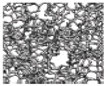 |  |
| Method | Arc-Discharge | Laser-Ablation | CVD |
|---|---|---|---|
| How | CNT growth on graphite electrodes during direct current arc-discharge evaporation of carbon in presence of an inert gas [39]. | To form CNTs, the vaporization of a mixture of carbon (graphite) and transition metals located in a target is used [40]. | Fixed bed method: decomposition of acetylene on graphite support iron particles at 700 °C [41]. |
| Yield rate | >75% | >75% | >75% |
| SWCNT or MWCNT | Both | Both | Both |
| Advantage | Simple, inexpensive, high-quality nanotubes. | Relatively high purity CNTs, room-temperature synthesis. | Simple, inexpensive, low temperature, high purity, large-scale production, aligned growth is possible. |
| Disadvantage | Purification of crude product is required, the method cannot be scaled, it must have a high temperature. | Method limited to the lab scale; crude product purification required. | Synthesized CNTs are usually MWNTs, defects. |
| Method | Morphology | Advantages | Disadvantages |
|---|---|---|---|
| Electrochemical deposition | Nanostructured film | Less time required; morphology can be controlled through the control of synthesis parameters such as time, temperature, etc. | Unsuitable for large-scale production |
| Hydrothermal method | Nanostructured film and powder | Large-scale production, easy control of morphology | High-temperature and time-consuming operations |
| Chemical bath deposition (CBD) | Nanostructured film | Faster than hydrothermal method, large-scale production, easy control of morphology | Only some metal oxide can be possible to synthesize |
| Sol–gel | Nanostructured film and powder | Low costs; controllable film texture, composition, homogeneity, and structural properties | Difficult to produce films with controlled porosity, needs the use of hard/soft templates |
| Chemical precipitation | Powders, colloidal nanostructures | Allows synthesis of composite electrode materials; efficient; easily implemented | Difficult to control morphology and may generate a waste product |
| Chemical Vapor Depositions (CVD) | Nanostructured film | High material yield than CBD; good film uniformity | Expensive equipment and relatively high costs |
| Type of Electrolyte | Voltage Window (V) | Ionic Conductivity (mS.cm−1) |
|---|---|---|
| Aqueous | ≤1.2 [9,28] | >400 [17,28] |
| Organic (NEt4BF4/PC) | 3.0 [28] | 13 [28] |
| Organic (NEt4BF4/ACN) | 2.7 [28] | 56 [28] |
| Ionic Liquids | 3–5 [9,17] | <15 [17,28] |
| Material | Potential Window/V | Specific Capacitance /F g−1 (Scan Rate or Current Density) | Electrolyte | Retention/% (Cycles) |
|---|---|---|---|---|
| ZrO2 carbon nanofibers | 0–1 | 140 (1 A g−1) | 6 M KOH | 82.6 (10,000) |
| RuNi2O4/rGO composites | 0–1 | 792 (1 A g−1) | 0.5 M Na2SO4 | 93 (10,000) |
| NiO/activated carbon composites | 0–0.4 | 568.7 (0.5 A g−1) | 2 M KOH | 90.6 (5000) |
| Ni0.25Co0.25oxide/carbon nanofibers | −1–0 | 431.2 (1 A g−1) | 6 M KOH | 94 (2000) |
| MnO/Fe2O3/carbon nanofibers | 0–1 | 437 (1 A g−1) | 6 M KOH | 94 (10,000) |
| ZnO/MnO/carbon nanofibers | 0–1.6 | 1080 (1 A g−1) | 6 M KOH | 96 (800) |
| Au-Mn3O4/GO nanocomposites | −0.2–1 | 475 (1 A g−1) | 0.5 M H2SO4 | 94 (10,000) |
| Bi2O3/MWCNT composites | −1.2–0.2 | 437 (1 A g−1) | 6 M KOH | 88.7 (3000) |
| NiO/MnO2/MWCNT composites | 0–0.55 | 1320 (1 A g−1) | 2 M KOH | 93.5 (3000) |
| Carbon nanosheets/MnO2/ NiCo2O4 composites | 0–1 | 1254 (1 A g−1) | 1 M KOH | 81.9 (5000) |
| ZrO2/C nanocomposites NiO/porous amorphous carbon nanostructure | 0–1 | 214 (1.5 A g−1) | 1 M H2SO4 | 97 (2000) |
| NiO/porous amorphous carbon nanostructure | 0–1.6 | 508 (1 A g−1) | 6 M KOH | 78 (3000) |
| Defective mesoporous carbon/MnO2 nanocomposites | −0.8–0.8 | 292 (0.5 A g−1) | 1 M Na2SO4 | 79 (2000) |
| Parameters | EDLC | Pseudocapacitor | Hybrid Capacitor |
|---|---|---|---|
| Material | Carbon-based materials, e.g., activated carbon, carbon nanotubes | Metal oxides, conducting polymers, e.g., NiO, MgO, PANI | Metal oxide/carbon-based materials, conducting polymer/carbon-based materials, e.g., Ni(OH)2/rGO, PANI/rGO |
| Storage mechanism | Non-faradic/electrostatic, electrical charge stored at the metal/electrolyte interface | Faradic, reversible redox reaction | Both faradic and non-faradic |
| Specific capacitance | Lower | Higher | Higher |
| Energy density | Low | High | High |
| Cycle Life/stability | High | Low | High |
| Voltage operation | High voltage and high-power operation | Low-voltage functioning is restricted by electrochemistry and the solvent’s solvent decomposition voltage | Increased cell voltage |
| Charge/discharge speed | Faster | --- | Slower |
Disclaimer/Publisher’s Note: The statements, opinions and data contained in all publications are solely those of the individual author(s) and contributor(s) and not of MDPI and/or the editor(s). MDPI and/or the editor(s) disclaim responsibility for any injury to people or property resulting from any ideas, methods, instructions or products referred to in the content. |
© 2023 by the authors. Licensee MDPI, Basel, Switzerland. This article is an open access article distributed under the terms and conditions of the Creative Commons Attribution (CC BY) license (https://creativecommons.org/licenses/by/4.0/).
Share and Cite
Escobar-Teran, F.; Perrot, H.; Sel, O. Carbon-Based Materials for Energy Storage Devices: Types and Characterization Techniques. Physchem 2023, 3, 355-384. https://doi.org/10.3390/physchem3030025
Escobar-Teran F, Perrot H, Sel O. Carbon-Based Materials for Energy Storage Devices: Types and Characterization Techniques. Physchem. 2023; 3(3):355-384. https://doi.org/10.3390/physchem3030025
Chicago/Turabian StyleEscobar-Teran, Freddy, Hubert Perrot, and Ozlem Sel. 2023. "Carbon-Based Materials for Energy Storage Devices: Types and Characterization Techniques" Physchem 3, no. 3: 355-384. https://doi.org/10.3390/physchem3030025
APA StyleEscobar-Teran, F., Perrot, H., & Sel, O. (2023). Carbon-Based Materials for Energy Storage Devices: Types and Characterization Techniques. Physchem, 3(3), 355-384. https://doi.org/10.3390/physchem3030025