
A Wide Bandwidth Vivaldi Antenna Suitable for 5G/6G Communication Utilizing a CMOS 0.18 μm Process

Department of Electronic Engineering, National Taipei University of Technology, Taipei 10608, Taiwan
*
Author to whom correspondence should be addressed.
Telecom 2024, 5(2), 400-415; https://doi.org/10.3390/telecom5020020
Submission received: 21 February 2024
/
Revised: 7 May 2024
/
Accepted: 9 May 2024
/
Published: 14 May 2024
Abstract
:This text proposes a Vivaldi structure array antenna, using a power divider structure. The composition includes an antenna array with four antennas, suitable for a wideband array structure antenna in the 100 GHz frequency band. The goal is to address the challenges faced by monolithic systems in modern wireless communications, particularly the issue of the inapplicability of antennas on silicon substrates. The Vivaldi antenna was chosen for its wide bandwidth, high efficiency, and stable radiation pattern. It combines the characteristics of a wide scanning angle and ultra-wide bandwidth. Through integration with CMOS technology, the developed antenna achieved a bandwidth of 85.47–102.40 GHz. The peak gain reached −4 dBi, corresponding to a bandwidth of 17.7%. And the antenna volume was only 1.2 mm × 1.2 mm, demonstrating its immense potential in high-frequency wireless applications.
1. Introduction
In the current era, there is considerable demand for high-speed communications [1,2,3,4,5,6]. With the emergence of microstrip structures and the growing demand for lightweight and compact structures [7,8], Vivaldi commonly features a gradually narrowing slot design. Initially introduced by Gibson in 1979, the Vivaldi was further refined by Gazit. The Vivaldi operates over a wide bandwidth, offering high efficiency and a consistent radiation pattern as a travelling-wave [2,9]. Vivaldi has attracted attention due to its array featuring a wide scanning angle and ultra-wide bandwidth [10]. Recently, the frequency band from 30 to 300 GHz has been considered the key to addressing the data explosion in 5G/6G systems [11,12].
The advantage of the Vivaldi antenna lies in its extremely wide bandwidth. Successfully designed Vivaldi antennas are widely used in wireless communication systems, radar, telescopes, remote sensing systems, satellite communications, and more. This is due to its stable performance characteristics, wide bandwidth, and high directivity. This allows for it to deliver optimal performance over a wide range of frequencies. It can be adjusted according to specific application requirements [2,7,8,13]. For instance, in wireless communication systems, to examine the composition of soil beneath the surface, ground-penetrating radar must send high-power pulses into the earth. To achieve deeper signal penetration and higher resolution, ground-penetrating radar antennas are required to operate in lower frequency bands, featuring high gain and ultra-wide bandwidth [9]. Vivaldi is a type of continuously scaled antenna, utilised in wideband wireless communication due to its large bandwidth and small lateral aperture among other prominent features [8]. The Vivaldi antenna has a compact footprint and features lower power consumption and complexity [2,12]. While there are other types of wideband antennas, the Vivaldi antenna has advantages over others in terms of weight, cost, end-fire radiation, and scanning angle capabilities, particularly in the simplicity of integrating the system [8,12,14]. However, in systems such as radar, communication, and various electronic devices, space is often at a premium. It is necessary to keep the spacing between antenna units to a minimum.
The operational principle of the Vivaldi antenna often leads to significant mutual coupling among neighbouring elements, primarily due to space-wave coupling. It can lead to adverse consequences, such as reduced antenna efficiency and inaccurate radiation patterns [12]. However, to enhance the gain of the antenna, researchers have proposed various methods. Among them, antenna arrays, etched grooves, and techniques such as dielectric lenses have gained widespread use. Typically, antenna arrays can significantly improve gain but require consideration of coupling and power distribution, making the design complex. Additionally, creating slots in the antenna can decrease its operating frequency and enhance its gain, yet this measure reduces the antenna’s directivity. Adding a high dielectric constant to the antenna enables it to reliably boost its gain, although the extent of improvement is confined [9]. To achieve high performance, one often overlooks the miniaturisation in systems for communication. Therefore, researching small-sized, wideband, high-gain antennas is extremely important [15,16,17].
As mentioned, the Vivaldi antenna has a very wide bandwidth and can be adjusted according to specific application requirements, thereby offering optimal performance across a broad frequency range. Reference [7] employs a Vivaldi antenna array, phase switching, and an IC receiver for wireless broadband reception in 5G, achieving a gain of 8–13 dB, with a power consumption of 22.8 mV at 2 GHz. Reference [7] aims to increase the gain by using a decoupled director in a tapered slot. Around the slot, two symmetric sets of rectangular slits have been introduced to enhance the impedance matching. Consequently, the reflection coefficient (S11) is maintained below −12 dB across 1–4 GHz, achieving a gain between 4.9 and 11.6 dBi, and even hitting 11.6 dBi within the 8–28 GHz range.
In this study, we introduce a design for an array, using Vivaldi antennas to provide the wide bandwidth and gain for 5G mobile phones [18]. Inherently, Vivaldi antennas have resistance tolerances in circuit manufacturing thanks to their wideband and high-gain traits. Hence, during the production process, its realisation is not more complex than that of Yagi antennas or dipole antennas [11]. In other words, the Vivaldi antenna exhibits a significant tolerance for smartphones.
Based on the results from simulations and measurements, the antenna in question is deemed appropriate for use on 5G mobile devices. The compact Vivaldi antenna, utilising W-band chips with standard 0.18 μm CMOS fabrication technology, has dimensions of 1200 µm × 1200 µm. The frequency range covered is from 85 to 102 GHz [19]. Utilising the Vivaldi antenna as a power divider, the antenna is then manufactured on a CMOS 0.18 μm process for the second part, where structural modifications are made to enhance the lower operating frequencies. A parameter analysis is performed to examine the interplay between the cavity and the antenna, with the aim of identifying the optimal performance for the antenna [20,21,22,23]. Additionally, parameter studies are conducted to evaluate the influence of critical parameters on the performance of the Vivaldi [16,18]. The third part describes the evolution process of the Vivaldi antenna, while the fourth part discusses the final results obtained as well as the measurement results [14]. The results of the simulations show that this symmetric Vivaldi antenna fulfils the standard needs of mobile applications [11].
2. Design of Antenna
2.1. Geometry of the Antenna
The initial geometric structure of the Vivaldi, shown in Figure 1a,b, adopts the 0.18 μm CMOS process, with dimensions of 1200 µm × 1200 µm × 533.4 µm, detailed dimensions are shown in Table 1. It is made up of approximately 1/4 elliptical structures. For achieving excellent impedance matching over a very broad bandwidth, a 50-ohm microstrip line accompanied by a grounded plane serves as the feed for the antenna. To further improve the impedance matching at lower frequencies, small elliptical cuts are used beneath each individual Vivaldi antenna. Slots are incorporated within the antenna design to ensure compliance with the process area, in line with the manufacturing process. Due to the lower gain of chip antennas, this article designs a power divider to achieve high gain with a 1 × 4 array antenna configuration. In response to the losses associated with the implementation of the antenna on a chip, the proposed Vivaldi antenna is manufactured using a 0.18 μm CMOS process. The Vivaldi has six layers of silicon dioxide (M1–M6) as the top metal layers, Figure 1c, along with Metal1 to Metal6, integrated with a silicon substrate. The silicon substrate has a thickness of 500 µm. The top metal layer Metal6 is designated as the layer, having a thickness of 2.34 µm.
Equation (1) below defines the curve of the slot index.
C1 = 0.185, d = 0.150, and C2 = 0.230. (The slot factor curve of an antenna is a graph used to describe how the performance of the antenna changes with variations in its shape and size.) The antenna elliptical curve E3 is defined by the following Equation (2).
From Figure 2, it is observed that when the frequency is 85.47 GHz, the reflection coefficient is below −10 dB. The applicable frequency range is 85.47–102.36 GHz. At a frequency of 95.5 GHz, the deepest point of the return loss is −23.60 dB. The overall bandwidth where the return loss is below −10 dB is 16.89 GHz.
2.2. Antenna Design
The progression of the antenna design process is clearly illustrated, as shown in Figure 3a. The antenna (Type 1) is the original symmetric Vivaldi antenna, utilising a rectangular and 50 Ω feedline. For the antenna (Type 2), a small elliptical cut is employed in the feed-in position of the antenna. The antenna (Type 3) incorporates elliptical arc-shaped structures to cut the antenna (Type 2), while the antenna (Type 4) is composed of approximately 1/4 elliptical structures for cutting. Both antennas are proposed in this paper. Figure 3b shows a stacked plot comparison of the reflection coefficient during the Vivaldi evolution. The antenna (Type 1) is analysed using a rectangular shape. When the rectangular dimensions are 275 × 210 µm, from the analysis graph, it can be observed that at a frequency of 80.42 GHz, the return loss is below −10 dB. The usable frequency range is 80.42–95.63 GHz. At a frequency of 88 GHz, the deepest point of the return loss is −26.144 dB. The overall bandwidth where the return loss is below −10 dB is 15.21 GHz. A small elliptical cut, with a radius of 125 µm, is utilised from the feed-in point to enhance the antenna bandwidth (Type 2). Following this modification, the simulations are carried out.
From the analysis graph of the simulation results, it can be observed that at a frequency of 81.61 GHz, the return loss is below −10 dB. This represents an increase of 2.21 GHz compared to the rectangular shape. Furthermore, the maximum frequency value has increased from 95.63 to 98.69 GHz. The usable frequency range is from 82.63 to 98.69 GHz, which is an increase of 0.85 GHz in bandwidth compared to before the cut. At a frequency of 91 GHz, the deepest point of the return loss is −20.98 dB. The overall bandwidth where the return loss is below −10 dB is 16.06 GHz. The antenna (Type 3) involves cutting antenna (Type 2) with arc-shaped elliptical structures, followed by simulations. From the analysis graph of the simulation results, it can be observed that at a frequency of 82.67 GHz, the return loss is below −10 dB. This represents an increase of 1.03 GHz compared to the rectangular shape. Additionally, the maximum frequency value has increased from 98.69 to 100.36 GHz. The usable frequency range is from 83.67 to 100.36 GHz, which is an increase of 0.63 GHz in bandwidth compared to before the cut. At a frequency of 93 GHz, the deepest point of the return loss is −26.12 dB. The overall bandwidth where the return loss is below −10 dB is 16.69 GHz. The antenna (Type 4), which is the antenna structure proposed in this paper, is composed of approximately 1/4 elliptical structures with a radius of 325 µm. After the cut, the simulations are conducted. From the analysis graph of the simulation results, it can be observed that at a frequency of 85.47 GHz, the return loss is below −10 dB. The maximum frequency value has increased from 100.36 to 102.36 GHz, resulting in an additional bandwidth of 2 GHz compared to before the cut. The usable frequency range is from 85.47 to 102.36 GHz. The area is smaller than before the cut, and the bandwidth is wider. At a frequency of 95.5 GHz, the deepest point of the return loss is −23.60 dB. The overall bandwidth where the return loss is below −10 dB is 16.89 GHz.
2.3. Antenna Parameterisation Process
Figure 3 confirms the approximate coefficients of the Vivaldi antenna in this paper. Using electromagnetic simulation software to integrate the Vivaldi, the gain of the array is enhanced in a confined space. Antennas should be placed as closely together as feasible.
However, if the spacing between antennas is excessively narrow, the overall isolation of the antennas deteriorates, resulting in a reduction in the performance of the antenna array. A parameter analysis is carried out on the W1 and L1 dimensions of the antenna to determine the impact of the radiating element’s size on its performance, aiming to identify the optimal antenna length. This approach also allows for the study of the interplay between the cavity and the antenna, as well as the search for the optimal performance of the antenna [12,16,18].
Firstly, a parameter analysis is conducted on the radiating element of a single antenna, as shown in Figure 4a. In Figure 4b, when L2 = 217 µm, S11 is below −10 dB at 114.63 GHz, the deepest point being −11.63 dB, and the bandwidth is from 114.63 to 124.03 GHz. When L2 = 221 µm, S11 is below −10 dB at 115.27 GHz, the deepest point being −11.22 dB, and the bandwidth is 115.27–123.52 GHz. When L2 = 225 µm, S11 is below −10 dB at 113.43 GHz, with the deepest point being −12.28 dB, and the bandwidth is from 113.43 to 124.67 GHz. Therefore, after the parameter analysis, when the length of the radiating element L2 is 225 µm, the bandwidth is the widest and the reflection coefficient has the lowest value. Furthermore, the parameter analysis is performed on W1 as shown in Figure 4a. In Figure 5b, when W1 = 192 µm, S11 is below −10 dB at 116.11 GHz, the deepest point being −12.5 dB, and the bandwidth is from 116.11 to 125.82 GHz. When W1 = 206 µm, S11 is below −10 dB at 115.76 GHz, with the deepest point being −12.02 dB, and the bandwidth is from 115.76 to 125.79 GHz. When W1 = 220 µm, S11 is below −10 dB at 112.72 GHz, with the deepest point being −13.04 dB, and the bandwidth is 112.72–124.66 GHz. Therefore, after the parameter analysis, when the width of the radiating element W1 is 220 µm, the bandwidth is the widest and the reflection coefficient has the lowest value [21].
To ensure that the antenna impedance matching performance meets the required standards, a parametric analysis was performed on the W7 part of the power divider, Figure 6a. Figure 6b shows the results of the S11 parameter analysis, while Figure 7a shows the results of the S21 one, and Figure 7b shows the S31 parameter analyses. The results indicate that S21 and S31 exhibit no significant differences, as both are −3.5 dB. However, when W7 = 5 µm, S11 has the deepest resonance point at 78 GHz, with a value of −30.8 dB. Therefore, W7 = 5 µm is chosen as the design parameter for the power divider.
Next, the Vivaldi antenna array is configured in a 1 × 2 format and then the parameter analysis is performed on the radiating elements of the antenna, as shown in Figure 8a. In Figure 8b, when W4 = 22 µm, S11 is below −10 dB at 93.21 GHz, with the deepest point being −33.24 dB, and the bandwidth is 93.21–113.67 GHz. When W4 = 18 µm, S11 is below −10 dB at 84.73 GHz, with the deepest point being −25.07 dB, and the bandwidth is 84.73–102.15 GHz. When W4 = 14 µm, S11 is below −10 dB at 89.92 GHz, with the deepest point being −37.1 dB, and the bandwidth is from 89.92 to 109.72 GHz. From the results in Figure 7, when the width of the radiating element W4 is 14 µm, the bandwidth is the widest and the reflection coefficient has the lowest value. Therefore, the results of the S-parameter analysis for W4 = 14 µm are adopted as the width of W4 for the antenna in this paper.
Similarly, a parameter analysis is performed on the radiating elements of a 1 × 2 Vivaldi, as shown in Figure 9a. In Figure 9b, when W7 = 15 µm, S11 is below −10 dB at 89.81 GHz, the deepest point being −17.16 dB, and the bandwidth is 89.81–103.49 GHz. When W7 = 10 µm, S11 is below −10 dB at 87.21 GHz, with the deepest point being −20.13 dB, and the bandwidth is from 87.21 to 102.84 GHz. When W7 = 5 µm, S11 is below −10 dB at 86.12 GHz, with the deepest point being −21.34 dB, and the bandwidth is 85.47–102.40 GHz. From the results in Figure 8, when the width of the radiating element W7 is 5 µm, the bandwidth is the widest and the return loss has the lowest value. Therefore, the results of the S-parameter analysis for W7 = 5 µm are adopted as the width of W7 for the antenna in this paper.
Next, a parameter analysis is conducted on the radiating elements of the 1 × 4 Vivaldi antenna, as shown in Figure 10a. In Figure 10b, when W5 = 22 µm, S11 remains above −10 dB for all frequency bands. When W5 = 18 µm, S11 is below −10 dB at 109.85 GHz, with the deepest point −11.56 dB, and the bandwidth is 109.85–128.92 GHz. When W5 = 14 µm, S11 is below −10 dB at 108.47 GHz, with the deepest point being −12.51 dB, and the bandwidth is from 108.47 to 128.88 GHz. From the results in Figure 9, when the width of the radiating element W5 is 14 µm, the bandwidth is the widest and the return loss has the lowest value. Therefore, the results of the S-parameter analysis for W5 = 14 µm are adopted as the width of W5 for the antenna in this article.
Similarly, a parameter analysis is conducted on the radiating elements of the 1 × 4 Vivaldi, as shown in Figure 11a. In Figure 11b, when W3 = 15 µm, S11 remains above −10 dB for all frequency bands. When W3 = 10 µm, S11 remains above −10 dB for all frequency bands. When W3 = 5 µm, S11 is below −10 dB at 80.12 GHz, with the deepest point being −10.36 dB, and the bandwidth is 80.12–127.56 GHz. From the results in Figure 10, when the width of the radiating element W3 is 5 µm, the bandwidth is the widest and the reflection coefficient has the lowest value. Although, when W3 is 18 µm, the bandwidth is wider than at 14 µm, it is not within the designed frequency band for this application. Therefore, the S-parameter of the analysis results for W3 = 5 µm are adopted as the width of W7 for the antenna in this paper.
Finally, the Vivaldi antenna array is configured in a 1 × 4 format, and a parameter analysis is conducted on the radiating elements, Figure 12a, of the antenna. In Figure 12b, when W5 = 22 µm, S11 is below −10 dB at 88.64 GHz, the deepest point being −16.91 dB, and the bandwidth is 88.64–102.71 GHz. When W5 = 18 µm, S11 is below −10 dB at 87.02 GHz, the deepest point being −30.50 dB, and the bandwidth is 87.02–103.28 GHz. When W5 = 14 µm, S11 is below −10 dB at 86.65 GHz, with the deepest point being −48.61 dB, and the bandwidth is from 86.65 to 103.13 GHz. From the results in Figure 11, it can be observed that when the width of the feeding transmission line is 14 µm, the bandwidth is the widest, the deepest point is reached, and the frequency range matches the desired range for this design. Therefore, the results of the S-parameter analysis for W5 = 14 µm are adopted as the width of W5.
Similarly, a parameter analysis is conducted on the radiating elements of the power divider, Figure 13a. In Figure 13b, when W7 = 15 µm, S11 is below −10 dB at 89.92 GHz, with the deepest point being −33.24 dB, and the bandwidth is 89.92–109.72 GHz. When W7 = 10 µm, S11 is below −10 dB at 84.73 GHz, with the deepest point being −30.50 dB, and the bandwidth is from 84.73 to 102.15 GHz. When W7 = 5 µm, S11 is below −10 dB at 93.21 GHz, the deepest point being −36.93 dB, and the bandwidth is 93.21–113.67 GHz. From the simulation results in Figure 12, it can be observed that when the power divider width of the feeding transmission line is 5 µm, the bandwidth is the widest, the deepest point is reached, and the frequency range matches the desired range for this design. Therefore, the results of the S-parameter analysis for W7 = 5 µm are adopted as the width of W7.
3. Antenna Simulation and Measurement
3.1. Simulation and Measurement Results
It is well known that the return loss is a critical indicator for evaluating the impedance matching between an antenna or transmission line and its load. Ideally, one wants the impedance of the antenna or transmission line to be perfectly matched with the impedance of its load. This maximises the transmission efficiency of the power and reduces the energy losses. If there is an impedance mismatch, more energy will be reflected back, leading to decreased efficiency as it returns in the form of reflected waves. The current distribution diagram for the Vivaldi antenna at different frequencies is shown in Figure 15, while Figure 16 shows the overlay of the simulated and measured responses of the Vivaldi antenna. Throughout the entire X-band, the observations indicate that the return loss measured falls below −10 dB. It is worth noting that minor manufacturing tolerances are inevitable. In practical measurements, passive antennas need to be terminated with a 50-ohm load, while active antennas are fed power. The observations reveal that the simulation and measured gain of the Vivaldi antenna exhibit good consistency. However, minor fluctuations at certain frequency points may be attributed to impedance matching or the effects of the GSG connectors used in the measurements. Overall, the measurement results are nearly identical to the simulated ones.
3.2. Gain and Measurement
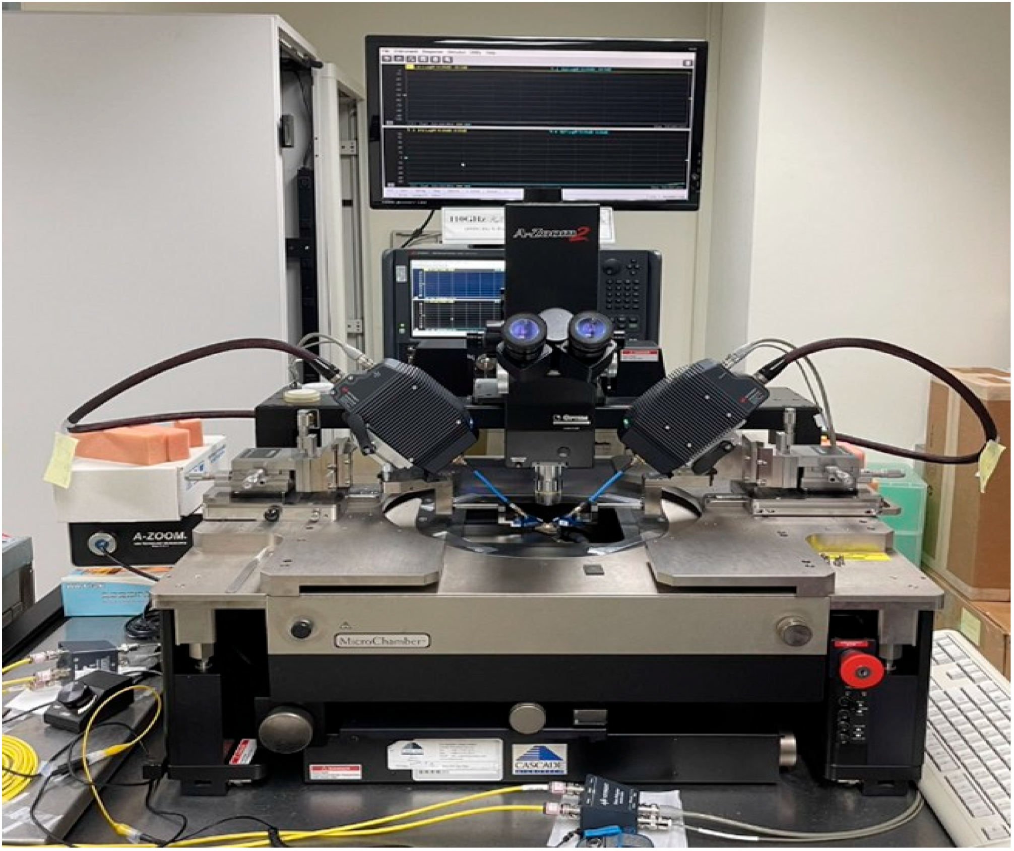
The gain of a chip antenna is an important indicator of its performance. A high-gain antenna can concentrate more energy in a specific direction, thereby achieving a greater communication distance. However, increasing directionality may reduce coverage in other directions. Figure 17 shows the gain plot, with a peak gain of −4 dBi at 98 GHz. Figure 18 illustrates the gain pattern of the antenna on different surfaces, while Figure 19 provides a 3D representation of the gain pattern, indicating a gain of −4.5 dBi. Figure 20 shows a microscopic image of the antenna during the measurement, with visible GSG markings. Figure 21 shows the measurement setup, covering the range 70–140 GHz and utilising the GSG probe.
Table 2 presents a comparison between the antenna proposed in this study and various other types of antennas on the chip. Due to the wide bandwidth characteristics of the Vivaldi antenna, it outperforms [5,6,17,19,24] in terms of bandwidth. Additionally, in terms of the Vivaldi antenna size, the one proposed in this document measures 1.2 × 1.2 mm, showing no significant difference from other types of antennas.
4. Discussion
Due to silicon’s higher conductivity, this may adversely affect the radiation performance of the antenna, especially in typical six-metal-layer CMOS processes. Such process structures can lead to a decrease in antenna efficiency due to the coupling effects between the antenna and the silicon substrate, as well as the conductivity of the substrate, causing energy losses. In this work, a wideband Vivaldi antenna suitable for the 100 GHz frequency band is proposed. Vivaldi antennas are renowned for their superior wideband characteristics, high efficiency, and travelling wave properties with stable radiation patterns, making them highly suitable for high-frequency applications. The Vivaldi antenna in this paper employs an array structure that not only enhances the antenna’s directivity of the antenna but also extends the scanning angles and bandwidth through the array design. The proposed CMOS Vivaldi antenna achieves a wide bandwidth of 16.93 GHz within the frequency range of 85.47–102.40 GHz, accounting for 17.7% of the entire band. The overall volume of the antenna is tightly controlled within a compact space of 1.2 × 1.2 mm. With a peak gain of −4 dBi, this represents a significant achievement considering the antenna’s size, especially given its operation in the high-frequency millimetre-wave band. This antenna finds wide-ranging applications in wireless communications, particularly in future 5G/6G high-frequency communications, satellite communication, long-range radar sensing, and other millimetre-wave applications.
Author Contributions
Conceptualization, M.-A.C.; methodology, M.-A.C.; software, M.-A.C.; validation, M.-A.C., C.-W.T. and K.-C.T.; formal analysis, M.-A.C.; investigation, M.-A.C.; resources, M.-A.C.; data curation, M.-A.C.; writing—original draft preparation, M.-A.C.; writing—review and editing, M.-A.C. and C.-W.T.; visualization, M.-A.C.; supervision, M.-A.C.; project administration, M.-A.C.; funding acquisition, M.-A.C. All authors have read and agreed to the published version of the manuscript.
Funding
This research received no external funding.
Data Availability Statement
Data is contained within the article. The original contributions presented in the study are included in the article, further inquiries can be directed to the corresponding authors.
Conflicts of Interest
The authors declare no conflicts of interest.
References
- Zhang, K.; Tan, R.; Jiang, Z.H.; Huang, Y.; Tang, L.; Hong, W. A compact, ultrawideband dual-polarized Vivaldi antenna with radar cross section reduction. IEEE Antennas Wirel. Propag. Lett. 2022, 21, 1323–1327. [Google Scholar] [CrossRef]
- Yin, Z.; He, G.; Yang, X.-X.; Gao, S. Miniaturized ultrawideband half-mode Vivaldi antenna based on mirror image theory. IEEE Antennas Wirel. Propag. Lett. 2020, 19, 695–699. [Google Scholar] [CrossRef]
- Wu, B.; Sun, X.-Y.; Zu, H.-R.; Zhang, H.-H.; Su, T. Transparent Ultrawideband Halved Coplanar Vivaldi Antenna with Metal Mesh Film. IEEE Antennas Wirel. Propag. Lett. 2022, 21, 2532–2536. [Google Scholar] [CrossRef]
- Dixit, A.S.; Kumar, S. A survey of performance enhancement techniques of antipodal Vivaldi antenna. IEEE Access 2020, 8, 45774–45796. [Google Scholar] [CrossRef]
- Mustacchio, C.; Boccia, L.; Arnieri, E.; Amendola, G. A gain levelling technique for on-chip antennas based on split-ring resonators. IEEE Access 2021, 9, 90750–90756. [Google Scholar] [CrossRef]
- Baniya, P.; Melde, K.L. Switched beam SIW horn arrays at 60 GHz for 360 reconfigurable chip-to-chip communications with interference considerations. IEEE Access 2021, 9, 100460–100471. [Google Scholar] [CrossRef]
- Shi, X.; Cao, Y.; Hu, Y.; Luo, X.; Yang, H.; Ye, L.H. A high-gain antipodal Vivaldi antenna with director and metamaterial at 1–28 GHz. IEEE Antennas Wirel. Propag. Lett. 2021, 20, 2432–2436. [Google Scholar] [CrossRef]
- Deng, J.-Y.; Cao, R.; Sun, D.; Zhang, Y.; Guo, L.-X. Bandwidth enhancement of an antipodal Vivaldi antenna facilitated by double-ridged substrate-integrated waveguide. IEEE Trans. Antennas Propag. 2020, 68, 8192–8196. [Google Scholar] [CrossRef]
- Cheng, H.; Yang, H.; Li, Y.; Chen, Y. A compact vivaldi antenna with artificial material lens and sidelobe suppressor for GPR applications. IEEE Access 2020, 8, 64056–64063. [Google Scholar] [CrossRef]
- Liu, Z.; Chen, Y.; Yang, S. In-band scattering cancellation techniques for Vivaldi antenna array. IEEE Trans. Antennas Propag. 2021, 70, 3411–3420. [Google Scholar] [CrossRef]
- Lee, W.-W.; Hwang, I.-J.; Jang, B. End-fire Vivaldi antenna array with wide fan-beam for 5G mobile handsets. IEEE Access 2020, 8, 118299–118304. [Google Scholar] [CrossRef]
- Zhang, H.; Wang, J.; Han, Y.; Zhu, R.; Liu, T.; Fu, X.; Liu, C.; Li, Y.; Chu, Z.; Qu, S. Isolation Enhancement for Vivaldi Antennas using Hyperbolic Metasurface. IEEE Trans. Antennas Propag. 2023, 71, 7650–7655. [Google Scholar] [CrossRef]
- Zhu, S.; Liu, H.; Wen, P.; Chen, Z.; Xu, H. Vivaldi antenna array using defected ground structure for edge effect restraint and back radiation suppression. IEEE Antennas Wirel. Propag. Lett. 2019, 19, 84–88. [Google Scholar] [CrossRef]
- Zhou, L.; Tang, M.; Qian, J.; Zhang, Y.-P.; Mao, J. Vivaldi antenna array with heat dissipation enhancement for millimeter-wave applications. IEEE Trans. Antennas Propag. 2021, 70, 288–295. [Google Scholar] [CrossRef]
- Liu, X.; Zhu, Y.; Xie, W. A Miniaturized Wideband Directional Circularly Polarized Antenna Based on Bent Vivaldi Antenna Structure. IEEE Antennas Wirel. Propag. Lett. 2022, 22, 298–302. [Google Scholar] [CrossRef]
- Tianang, E.G.; Elmansouri, M.A.; Filipovic, D.S. Ultrawideband flush-mountable dual-polarized vivaldi antenna. IEEE Trans. Antennas Propag. 2020, 68, 5670–5674. [Google Scholar] [CrossRef]
- Yi, H.; Ozturk, E.; Koelink, M.; Krimmling, J.; Damian, A.A.; Debski, W.; van Zeijl, H.; Zhang, G.; Poelma, R.H. Antenna-in-Package (AiP) Using Through-Polymer Vias (TPVs) for a 122-GHz Radar Chip. IEEE Trans. Compon. Packag. Manuf. Technol. 2022, 12, 893–901. [Google Scholar] [CrossRef]
- Singh, M.; Parihar, M.S. Gain Improvement of Vivaldi MIMO Antenna With Pattern Diversity Using Bi-Axial Anisotropic Metasurface for Millimeter-Wave Band Application. IEEE Antennas Wirel. Propag. Lett. 2022, 22, 621–625. [Google Scholar] [CrossRef]
- Kim, H.; Jang, T.H.; Park, C.S. 60-GHz compact vertically polarized end-fire monopole-based Yagi antenna-in-package for wideband Mobile communication. IEEE Access 2022, 10, 111077–111086. [Google Scholar] [CrossRef]
- Burasa, P.; Djerafi, T.; Wu, K. A 28 GHz and 60 GHz dual-band on-chip antenna for 5G-compatible IoT-served sensors in standard CMOS process. IEEE Trans. Antennas Propag. 2020, 69, 2940–2945. [Google Scholar] [CrossRef]
- Tang, S.-Y.; Chen, J.; Xia, X.; Zhou, P.; Lu, H.; Chang, L.; Cheng, W.; Tao, H.; Zheng, S.; Li, Z. Terahertz On-Chip Aperture Antenna with through Substrate Vias for Enhanced Gain and Chip-Size Insensitivity in InP Technology. IEEE Trans. Antennas Propag. 2023, 71, 7184–7195. [Google Scholar] [CrossRef]
- Kong, S.; Shum, K.M.; Yang, C.; Gao, L.; Chan, C.H. Wide impedance-bandwidth and gain-bandwidth terahertz on-chip antenna with chip-integrated dielectric resonator. IEEE Trans. Antennas Propag. 2021, 69, 4269–4278. [Google Scholar] [CrossRef]
- Ballesteros, C.; Vega, S.; Santos, M.; Jofre-Roca, L. Short Asymmetrical Inductive Dipole Antenna for Direct Matching to High-Q Chips. IEEE Antennas Wirel. Propag. Lett. 2022, 22, 149–153. [Google Scholar] [CrossRef]
- Yu, Y.; Akhter, Z.; Shamim, A. Ultra-thin artificial magnetic conductor for gain enhancement of antenna-on-chip. IEEE Trans. Antennas Propag. 2022, 70, 4319–4330. [Google Scholar] [CrossRef]
Figure 1.
Side and top view of the Vivaldi. (a) Vivaldi side view; (b) Vivaldi top view; and (c) CMOS 0.18 μm process stack used.
Figure 1.
Side and top view of the Vivaldi. (a) Vivaldi side view; (b) Vivaldi top view; and (c) CMOS 0.18 μm process stack used.

Figure 2.
S-parameters of the Vivaldi antenna.
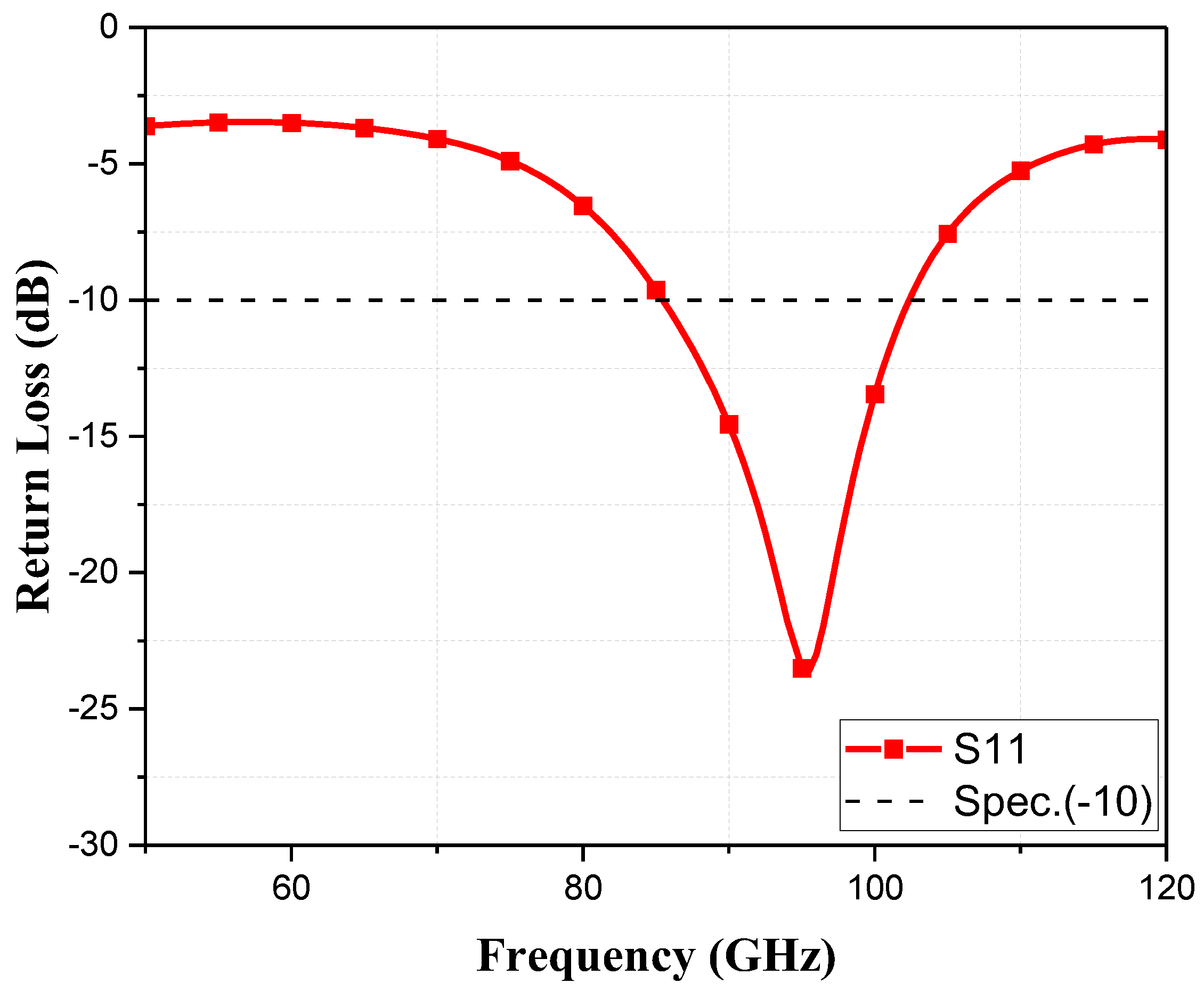
Figure 3.
(a) Antenna analysis; (b)antenna analysis S-parameter stacked plot.
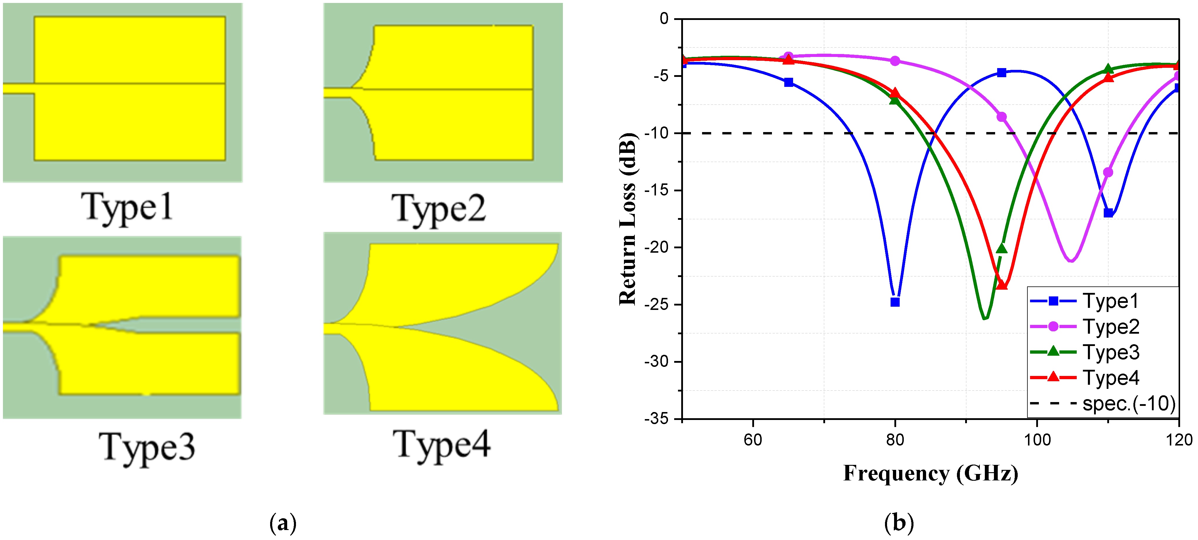
Figure 4.
(a) Diagram of L2’s location; (b) simulation of L2’s S-parameter.
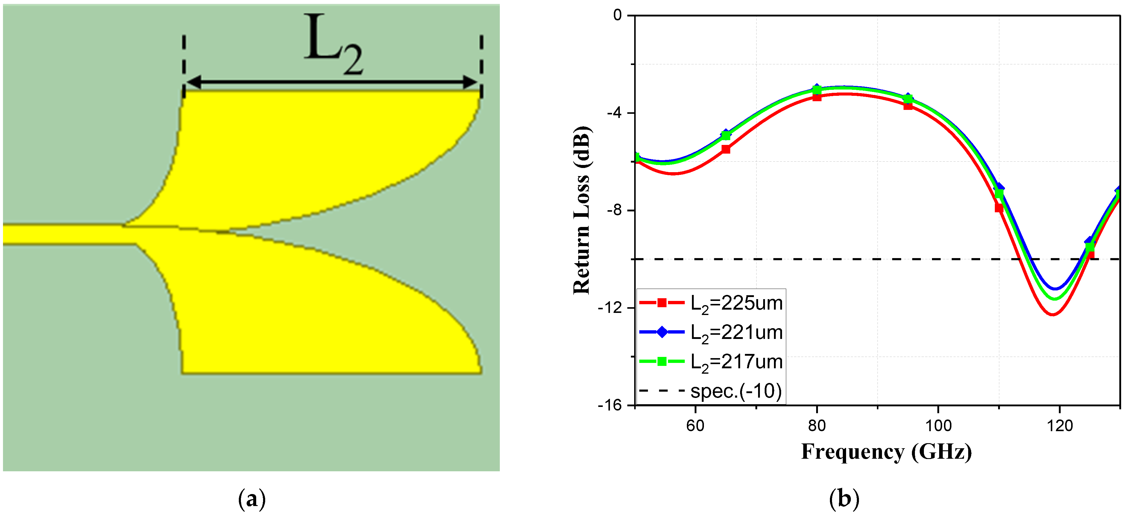
Figure 5.
(a) Diagram of W1’s location; (b) simulation of W1’s S-parameter.

Figure 6.
(a) Diagram of W7’s location; (b) S-parameter simulation of W7 with S-parameters.
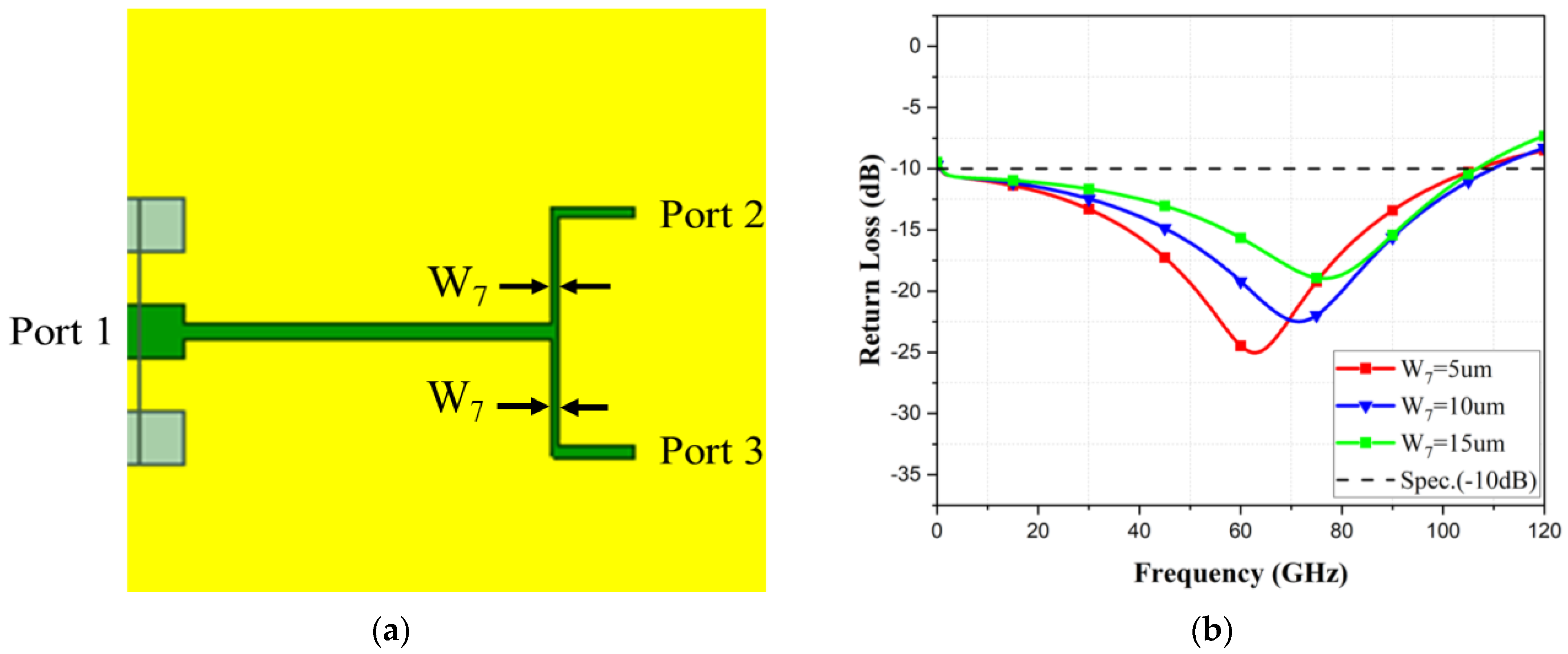
Figure 7.
(a) S-parameter simulation (S21) of W7; (b) S-parameter simulation (S31) of W7.
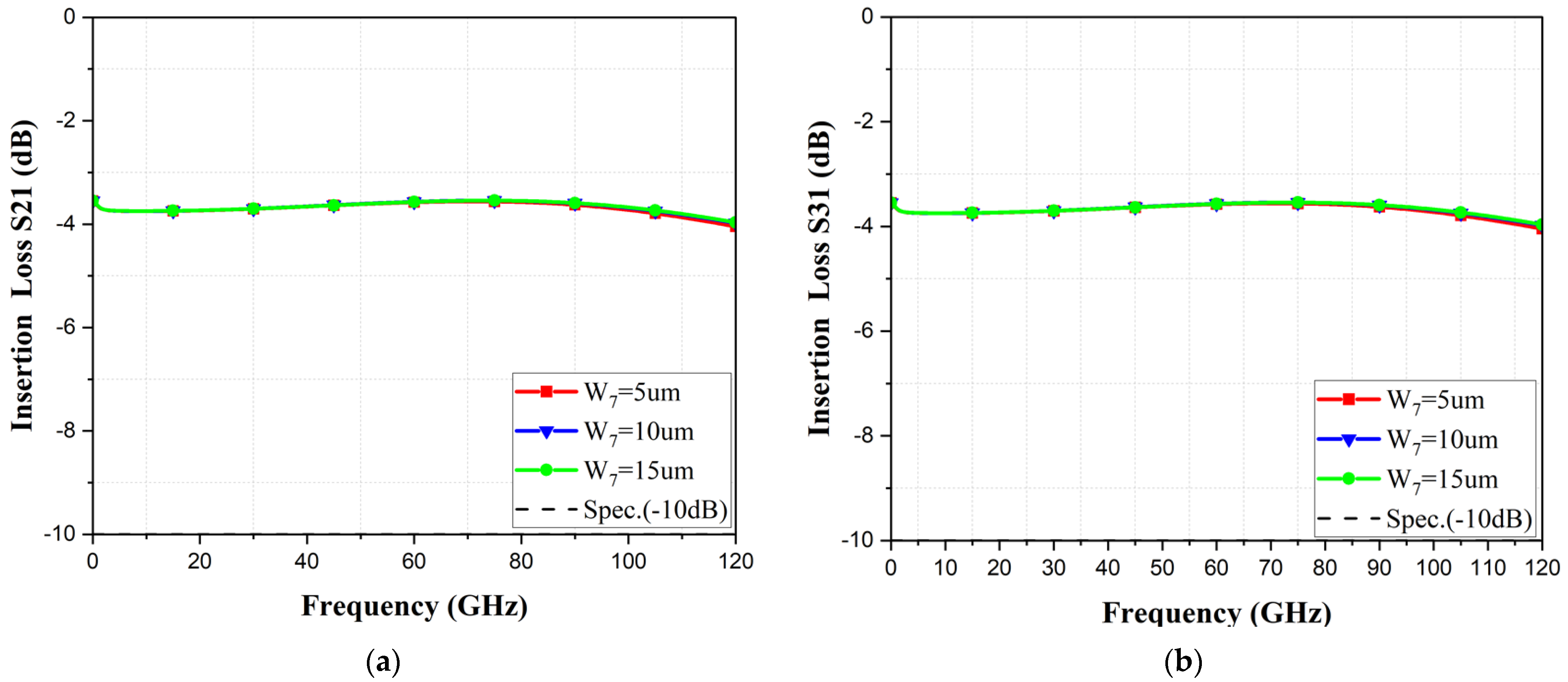
Figure 8.
(a) Diagram of W4’s location; (b) S-parameter simulation of W4.
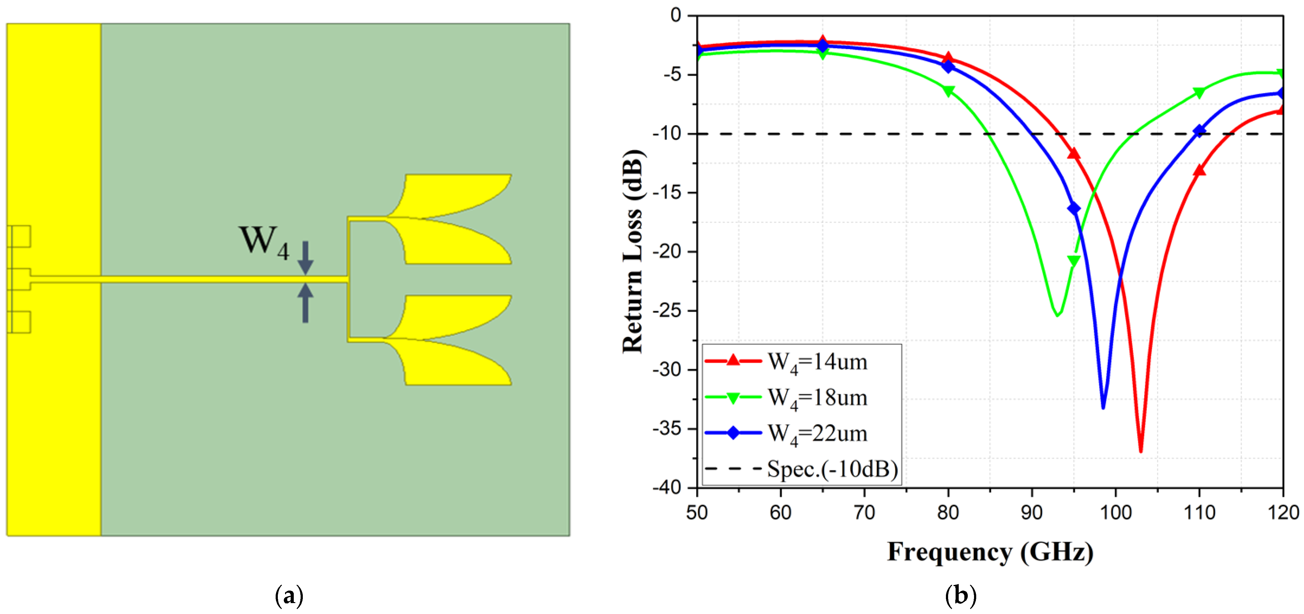
Figure 9.
(a) The diagram of W7’s location; (b) S-parameter simulation of W7.
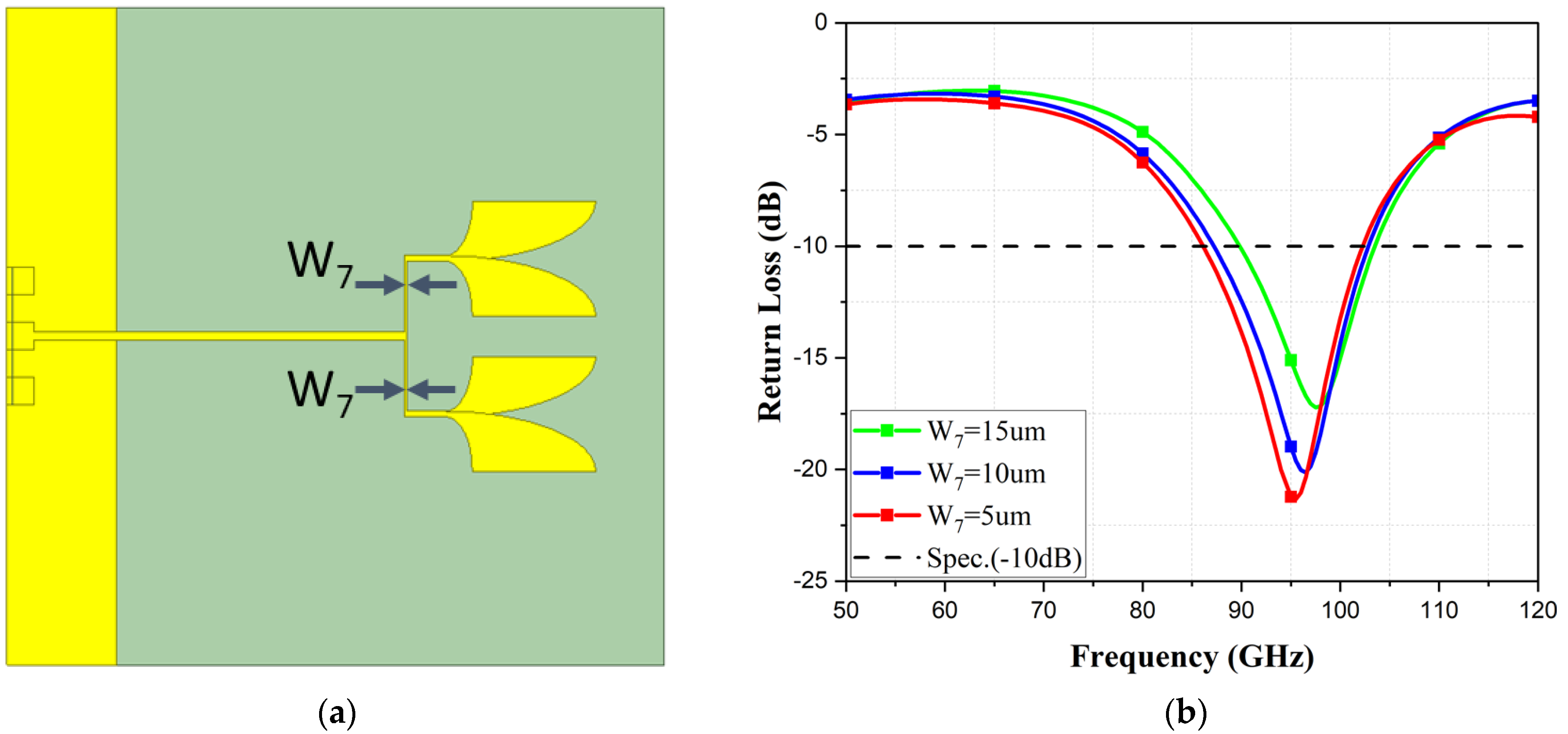
Figure 10.
(a) The diagram of W5’s location; (b) S-parameter simulation of W5.

Figure 11.
(a) The diagram of W3’s location; (b) S-parameter simulation of W3.
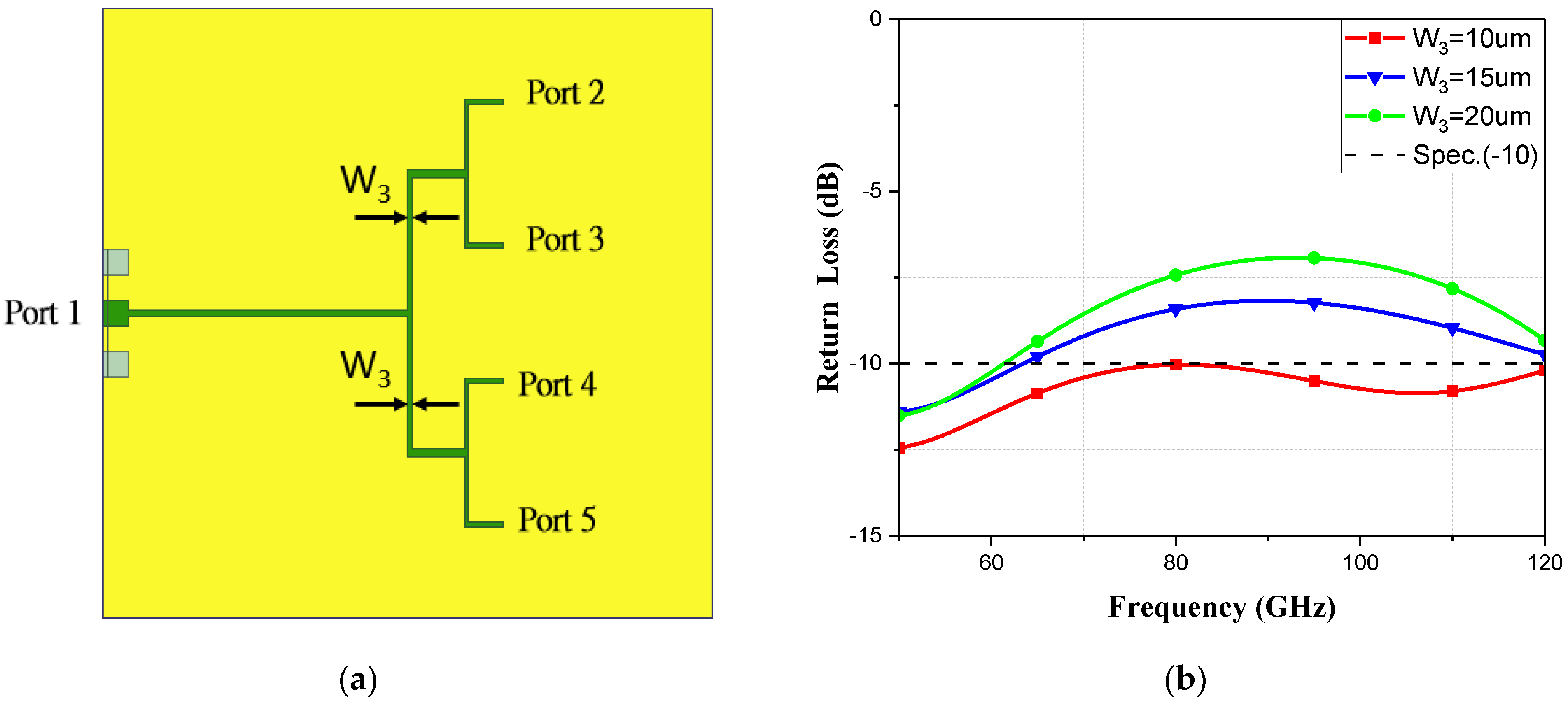
Figure 12.
(a) The diagram of W5’s location; (b) S-parameter simulation of W5.
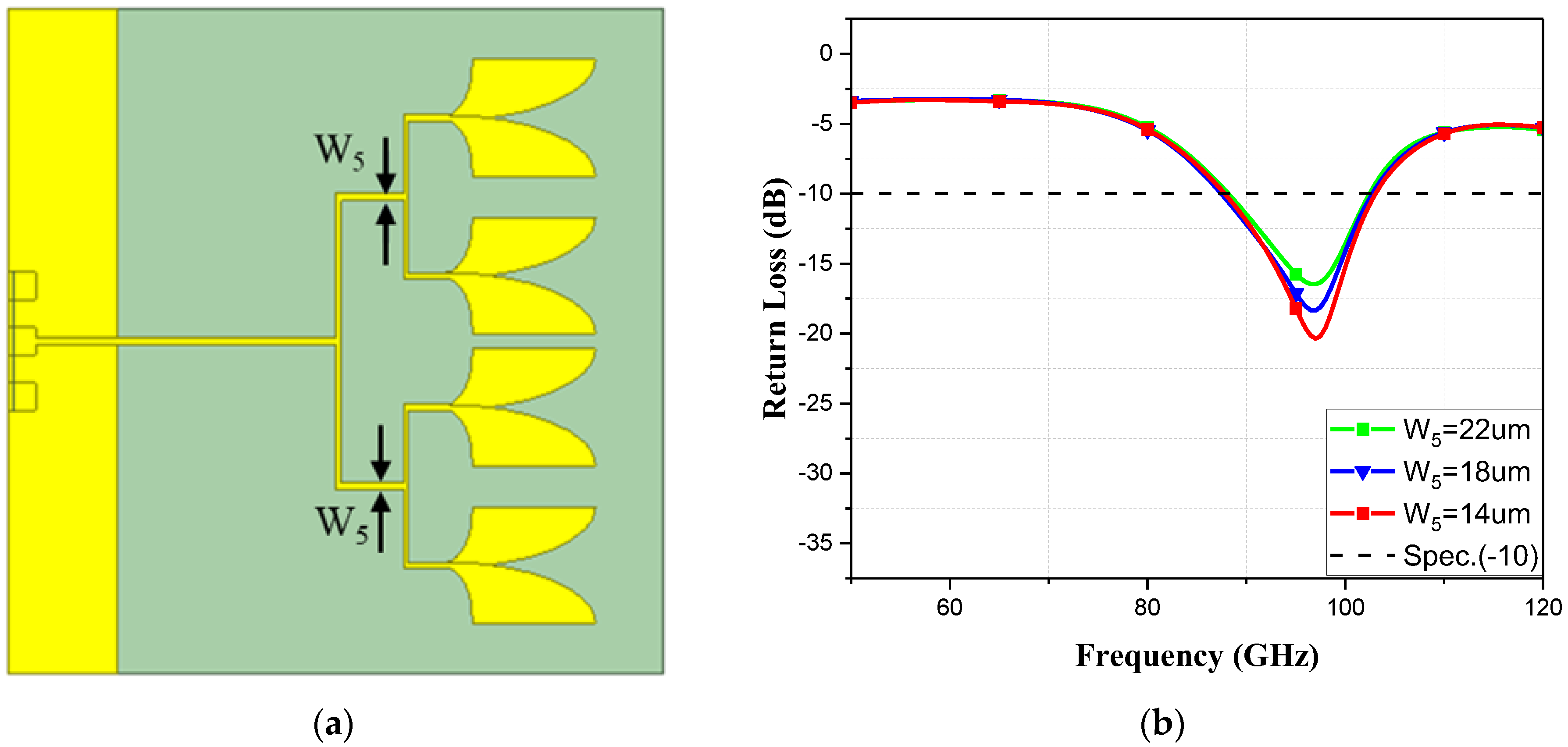
Figure 13.
(a) The diagram of W7’s location; (b) S-parameter simulation of W7.

Figure 14.
(a) Vivaldi antenna with slots; (b) S-parameter simulation with and without slots.

Figure 15.
Current distribution of the antenna at different frequencies: (a) at a frequency of 85 GHz; (b) at a frequency of 95 GHz; and (c) at a frequency of 102 GHz.
Figure 15.
Current distribution of the antenna at different frequencies: (a) at a frequency of 85 GHz; (b) at a frequency of 95 GHz; and (c) at a frequency of 102 GHz.
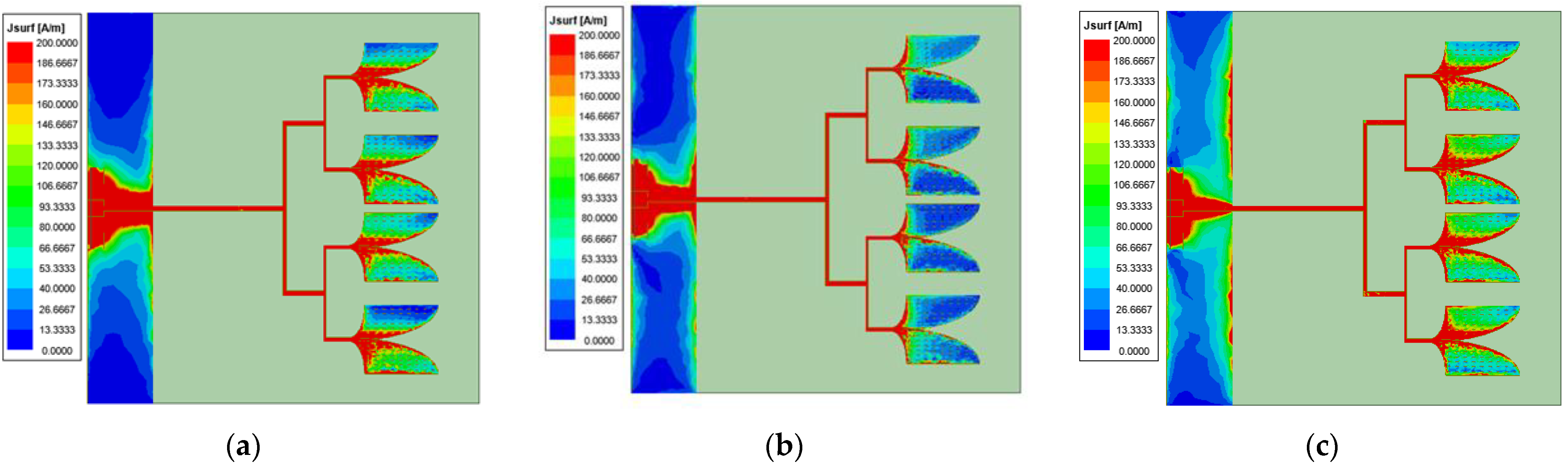
Figure 16.
S-parameter plot of the simulated and measured responses.
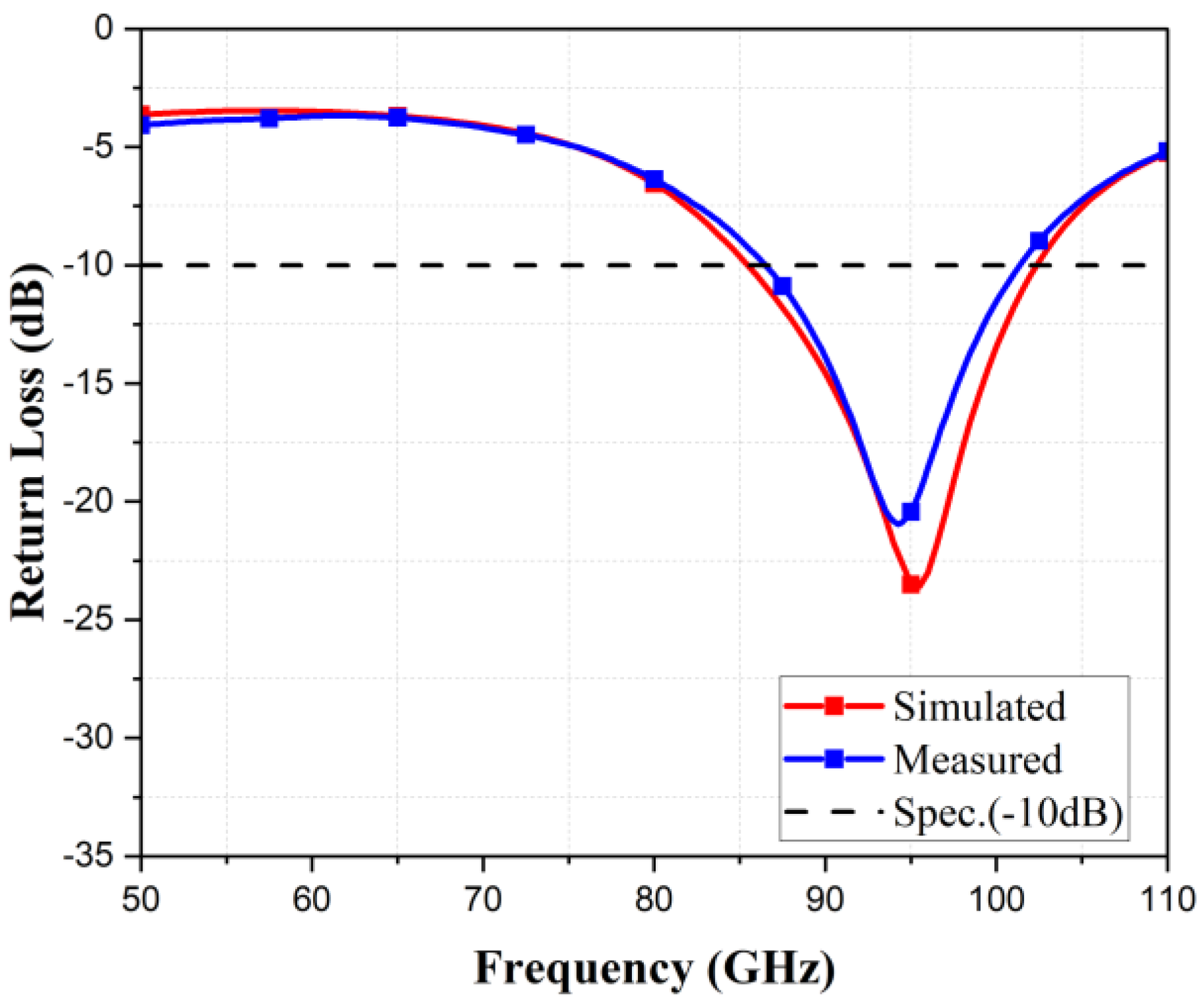
Figure 17.
Antenna gain graph.
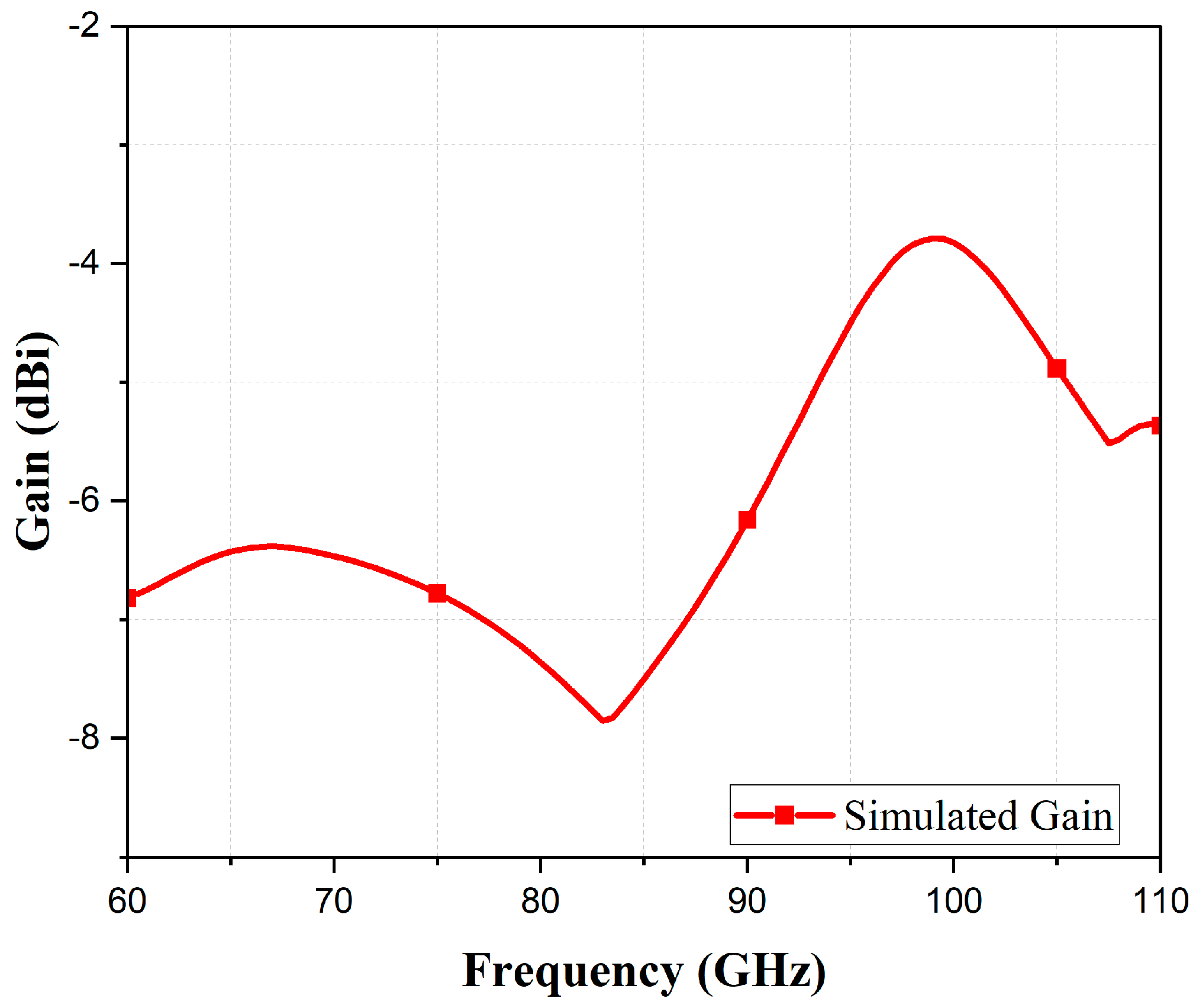
Figure 18.
(a) The 2D radiation pattern of the Vivaldi antenna (XY plane); (b) 2D radiation pattern of the Vivaldi antenna (YZ plane); and (c) 2D radiation pattern of the Vivaldi antenna (XZ plane).
Figure 18.
(a) The 2D radiation pattern of the Vivaldi antenna (XY plane); (b) 2D radiation pattern of the Vivaldi antenna (YZ plane); and (c) 2D radiation pattern of the Vivaldi antenna (XZ plane).

Figure 19.
Three-dimensional radiation pattern of the antenna.
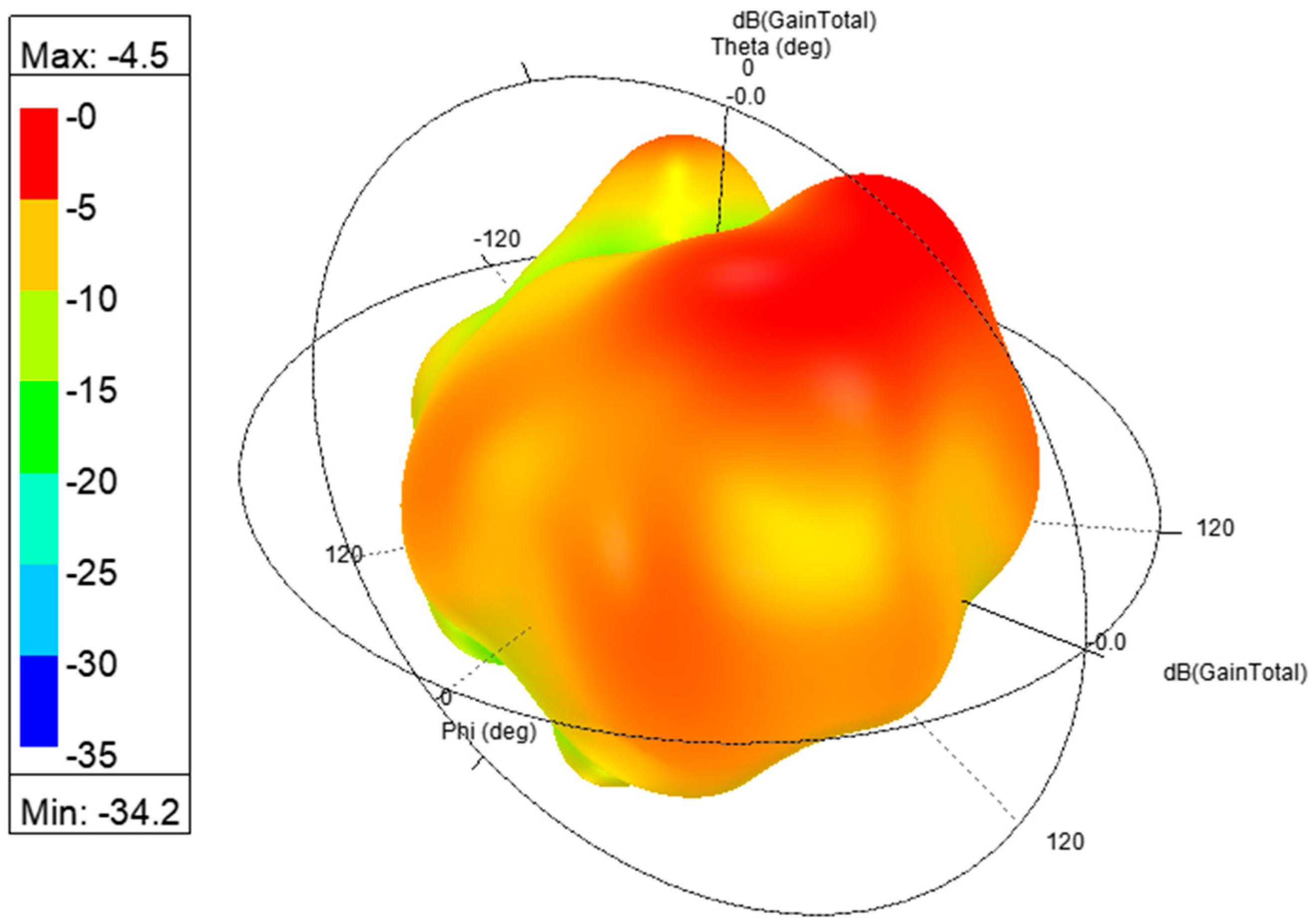
Figure 20.
Microscopic image of the antenna.

Figure 21.
Measurement setup.

Table 1.
Detail parameter. (Unit: µm).
| Length | Value | Width | Value |
|---|---|---|---|
| L1 | 600 | W1 | 210 |
| L2 | 225 | W2 | 125 |
| L3 | 274 | W3 | 10 |
| L4 | 125 | W4 | 14 |
| L5 | 260 | W5 | 14 |
| L6 | 1200 | W6 | 10 |
| L7 | 200 | W7 | 5 |
Table 2.
Comparison with Other Antennas.
| References | Antenna Type | * FBW (GHz) | Size (mm2) | Process |
|---|---|---|---|---|
| [5] | Monolithically Integrated antennas | 77–87 | 1.296 × 1.508 | 0.13 μm SiGe BiCMOS |
| [6] | (SNIR) antenna | 57.24–65.88 | N/A | Switching the directive beams of the arrays |
| [24] | System on chip | 93–95 | N/A | CMOS |
| [17] | Trough-polymer Via technology | 120–124.3 | 0.94 × 1.45 | SiGe BiCMOS |
| [19] | Yagi antenna | 57.6–67 | 0.74 × 1.14 | Glass substrate |
| This work | Vivaldi antenna | 85.47–102.4 | 1.2 × 1.2 | 0.18 μm CMOS |
* FBW = fractional bandwidth.
Disclaimer/Publisher’s Note: The statements, opinions and data contained in all publications are solely those of the individual author(s) and contributor(s) and not of MDPI and/or the editor(s). MDPI and/or the editor(s) disclaim responsibility for any injury to people or property resulting from any ideas, methods, instructions or products referred to in the content. |
© 2024 by the authors. Licensee MDPI, Basel, Switzerland. This article is an open access article distributed under the terms and conditions of the Creative Commons Attribution (CC BY) license (https://creativecommons.org/licenses/by/4.0/).
Share and Cite
MDPI and ACS Style
Chung, M.-A.; Ting, C.-W.; Tseng, K.-C. A Wide Bandwidth Vivaldi Antenna Suitable for 5G/6G Communication Utilizing a CMOS 0.18 μm Process. Telecom 2024, 5, 400-415. https://doi.org/10.3390/telecom5020020
AMA Style
Chung M-A, Ting C-W, Tseng K-C. A Wide Bandwidth Vivaldi Antenna Suitable for 5G/6G Communication Utilizing a CMOS 0.18 μm Process. Telecom. 2024; 5(2):400-415. https://doi.org/10.3390/telecom5020020
Chicago/Turabian StyleChung, Ming-An, Chung-Wu Ting, and Kuo-Chun Tseng. 2024. "A Wide Bandwidth Vivaldi Antenna Suitable for 5G/6G Communication Utilizing a CMOS 0.18 μm Process" Telecom 5, no. 2: 400-415. https://doi.org/10.3390/telecom5020020