Abstract
Electron beam–powder bed fusion (PBF-EB) is an additive manufacturing process that utilizes an electron beam as the heat source to enable material fusion. However, the use of a charge-carrying heat source can sometimes result in sudden powder explosions, usually referred to as “Smoke”, which can lead to process instability or termination. This experimental study investigated the initiation and propagation of Smoke using in situ high-speed synchrotron radiography. The results reveal two key mechanisms for Smoke evolution. In the first step, the beam–powder bed interaction creates electrically isolated particles in the atmosphere. Subsequently, these isolated particles get charged either by direct irradiation by the beam or indirectly by back-scattered electrons. These particles are accelerated by electric repulsion, and new particles in the atmosphere are produced when they impinge on the powder bed. This is the onset of the avalanche process known as Smoke. Based on this understanding, the dependence of Smoke on process parameters such as beam returning time, beam diameter, etc., can be rationalized.
1. Introduction and Conceptualization
Electron beam–powder bed fusion (PBF-EB) is an additive manufacturing (AM) method that employs an electron beam (e-beam) to scan across a powder bed to build up a desired geometry, layer by layer, in a vacuum environment, reaching beam deflection speeds of up to 105 m/s. As a consequence, the processing of materials susceptible to oxidation and cracking is possible, making it particularly suitable for processing high-performance materials. Despite its potential, various process challenges have hindered the full capabilities of PBF-EB. A significant obstacle is the “Smoke” phenomenon, which occurs when loosely packed powder particles covered by a thin layer of electrically insulative oxide become negatively charged by the e-beam. This accumulated charge causes powder scattering due to electrostatic forces, as described by Coulomb’s law. Smoke can lead to various issues, ranging from the removal of powder layers (in the best case), resulting in a lack of fusion defects in subsequent layers due to additional powder supply, to complete termination of the process due to the destruction of the powder bed [1,2].
Smoke is a pervasive challenge in PBF-EB to the extent that most machine manufacturers offer dedicated countermeasures. One common approach involves a preheating step before powder melting, which serves to reduce the likelihood of Smoke [3]. During preheating, a slightly sintered powder bed with a higher mechanical stability and better electrical conductivity is created. Sigl et al. proposed five methods to mitigate the Smoke: roughening the build plate, preheating the powder bed, enlarging the build platform, grounding the build plate, and using water atomized powder [2]. Freemelt AB, a Swedish company, has patented a method using UV light to neutralize the feedstock [4]. Similarly, Wayland Additive, based in the UK, introduced a NeuBeam® module that releases a stream of Argon ions, assisting in neutralizing both the negatively charged e-beam and the powder bed [5]. Chiba et al. adopted ball milling for powder before storage in the machine, which they found to be effective against the Smoke effect [6]. While these methods have shown some effectiveness in mitigating the Smoke, they often involve additional steps, equipment, or modifications to the existing process, which can be costly or may affect other aspects of the process.
In order to improve process stability, a more detailed understanding of the Smoke is necessary. Sigl et al. posit that the electrostatic effect is a plausible primary physical factor responsible for the Smoke [2]. Eschey et al. introduced an analytical model, which assumes the powder layer to be a parallel electrical connection between a resistor and a capacitor to analyze the charging behavior of powder layer. Building on a similar premise, Cordero et al. conceptualized the powder bed as an electrical equivalent circuit to simulate the charging behavior, treating the oxide film on powder particles as a capacitor that impedes electron flow and the metal core as a resistor [7]. In a related study, Yim et al. delved into the characteristics of the oxide film on powder particles, exploring how surface properties of powder particles influence the Smoke phenomenon [8]. Additionally, considerable efforts have been invested in observing the Smoke. For instance, Wang et al. used a high-speed camera positioned outside the vacuum chamber to monitor the Smoke, where three stages of Smoke development on a global scale were revealed [9]. Similarly, Ye et al. explored the potential of using an Electron Optical (ELO) imaging system to predict the occurrence of the Smoke [10]. However, due to limited monitoring possibilities for PBF-EB machines and the rapid evolution of the Smoke event, observations at the microscale have remained unavailable so far.
This study aimed to bridge the knowledge gap with a detailed microscale observation of Smoke. Two machines with two different materials were employed for this purpose. One machine was dedicated to observing the Smoke phenomenon on a global scale. The second machine was equipped with an in situ PBF-EB sample environment designed for high-speed synchrotron radiography to capture the powder trajectories during Smoke. The use of a high-intensity synchrotron X-ray source enables high frame rate recordings, while maintaining sharp resolution for high-speed imaging. While other researchers have observed the Smoke at the global scale, where individual powder particles are not discernible, our work provides novel insights by observing the phenomenon at the particle-level scale, where the behavior of individual particles can be analyzed. Observing the phenomenon at this scale is crucial, as it allows for a more detailed understanding of the interactions between particles and the e-beam, which is essential for developing more effective strategies to mitigate the Smoke. A multi-stage Smoke development is revealed, and a model for Smoke development is introduced, providing a more profound insight into the Smoke.
2. Material and Experimental Methods
The experimental approach was divided into two parts. The first part involved investigating the Smoke triggered by two different materials, namely CMSX-4® and Ti6Al4V. The Ti6Al4V was studied using the PBF-EB machine Freemelt® ONE (Freemelt AB, Mölndal, Sweden) equipped with a digital camera for a global-scale observation. For CMSX-4®, a sample environment specifically designed for high-speed synchrotron radiography was employed on the PBF-EB machine MiniMelt (Freemelt AB, Mölndal, Sweden) to capture detailed powder behavior during Smoke events. A point melting strategy was implemented to induce Smoke, as this approach has been shown to reliably trigger the Smoke in previous studies.
2.1. Smoke with Ti6Al4V on Freemelt® ONE
A preliminary Smoke test involving a stationary e-beam was performed using the Freemelt® ONE machine. No process gas was provided during this test. A custom-made stainless-steel plate with a deepening that is 500 µm thick was chosen as the subject for triggering Smoke, ensuring consistent triggering on a loose powder bed at a specific powder height. As depicted in Figure 1, the e-beam ramped up to the target beam current on a ramping plate situated above the build area and then impacted the loose powder bed at the center of the plate with the desired parameters. The material selected for this investigation was inert gas-atomized Ti6Al4V with a spherical particle shape (ELI grade 23; particle size 45–105 μm, Macon, France). The Smoke was monitored using a digital camera (Sony rx100 v, Tokyo, Japan) set at a frame rate of 500 fps, positioned outside the vacuum chamber.
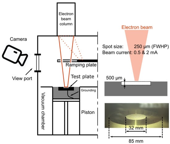
Figure 1.
Freemelt® ONE machine setup. The e-beam ramped up on a ramping plate before impacting the target powder bed. A high-speed camera (Sony rx100 v) was mounted next to the viewport to monitor the Smoke. A custom-made start plate ensured consistent Smoke triggering on a loose powder bed at a specific powder height. Details about the e-beam diameter and the start plate are provided on the right side of the image.
2.2. In Situ Radiography of Smoke with CMSX-4® on MiniMelt
The experiments were carried out at PETRA III, Deutsches Elektronen-Synchrotron (DESY, Hamburg, Germany) using a custom built PBF-EB machine, MiniMelt. MiniMelt was conceptualized and constructed as part of a German-Sweden Research collaboration to enable the investigation of PBF-EB with various synchrotron X-ray techniques, such as the high-speed radiography highlighted here. A detailed description of the sample environment and its capabilities is available in the study by König et al. [11]. The P61 High Energy Material Science Beamline, operated by Helmholz-Zentrum Hereon (Geesthacht, Germany) was selected to provide the required X-ray [12]. This synchrotron beam was a white beam with an energy range of 40 to 200 keV, offering a high enough brightness to measure through several millimeters of powder at image acquisition times in the range of 100 µs. The powder utilized was a Ni-based superalloy, CMSX-4®, EIGA atomized by TLS Technik GmbH & Co. Spezialpulver KG in Bitterfeld, Germany. This powder had a spherical morphology and a particle size distribution spanning from 45 to 105 µm. The reason for opting from Ti6Al4V to CMSX-4® is mainly due to absorption rate difference. At high X-ray energies, Ti6Al4V powder absorbs only a minimal portion of the beam’s energy, resulting in a low signal-to-noise ratio. Conversely, by switching from Ti6Al4V to CMSX-4®, the powder absorbs a greater amount of energy, thereby producing images with higher contrast.
A comprehensive depiction of the experimental setup is illustrated in Figure 2. The method employed closely mirrors conventional radiography. The white beam penetrates a thin layer of Kapton foil before entering the vacuum chamber, with the absorption from the Kapton window being negligible. Upon entering the chamber, the white beam strikes a powder hill, where part of the beam is obstructed. The transmitted beam is then converted into visible light using a cerium-doped GaGG+ scintillator (400 µm thick), which is actively cooled using N2 gas. Attenuators composed of 10 mm of Al and 200 µm of Ta were applied to harden the beam and reduce the intensity to not overheat the scintillators. The visible light is captured using a Phantom v2640 high-speed camera from Vision Research(Wayne, NJ, USA). The camera was set at a recording frame rate of 6600 Hz, with a spatial resolution of 2.7 µm.
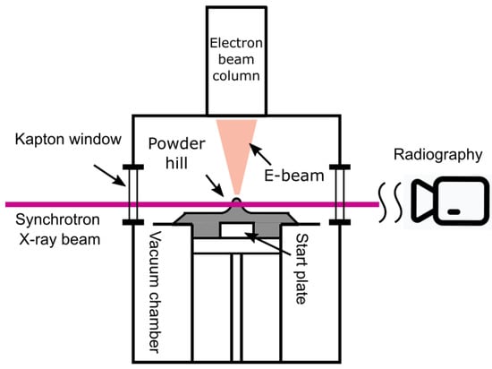
Figure 2.
MiniMelt machine setup. The machine has two observation windows made out of Kapton foil to maintain vacuum atmosphere and provide an X-ray in- and outlet. A powder hill, created by a customized rake, serves as an illumination object. The X-rays transmitted through the powder hill are captured by the radiography system provided by Helmholtz-Zentrum Hereon, consisting of GaGG+ scintillator and Phantom v2640 high-speed camera.
As previously mentioned, the powder hill served as the focus of illumination during this study, with a height of 2 mm from the tip of the hill to the start plate. This powder hill was created by recoating with fresh CMSX-4® powder shortly before the Smoke experiments. Despite the DESY beamline P61 providing a powerful white beam with an energy range from 40 to 200 keV, achieving horizontal penetration through the powder bed remains a significant challenge for synchrotron beams. A modified powder bed is common in the field of in situ synchrotron radiography from PBF-LB as well [13,14,15]. Sandwich-type powder bed designs were used in referenced studies, where the melt pool may directly contact the X-ray transparent walls. On the contrary, the trapezoidal shape of the powder hill, with a top width of 1 mm, is designed to ensure that the impact point or the melt pool created by a small beam size is completely surrounded by powder. This arrangement ensures that the dynamics of the melt pool during melting and the thermal diffusion processes both during and after melting are representative of the melt pool behavior in an industrial-scale PBF-EB process.
The e-beam from Freemelt® targeted the tip of the powder hill to initiate the Smoke event, with the beam current maintained at 1 mA and the beam diameter of 205 µm Full Width at Half Power (FWHP, measured with Freemelt®s built-in beam calibration client). Using a stationary e-beam has two major reasons. Firstly, the charging behavior of the powder bed is influenced by multiple process parameters, such as beam size, scanning speed, and the geometry of the preheating pattern, among others. The point melting strategy offers a more representative approach for examining powder behavior under continuous charging during the Smoke phenomenon. Secondly, as outlined by Ye et al. [10], Smoke can originate from any random spot within the preheating area. Given the limited field of view (FOV), 3 mm by 2 mm, offered by Phantom v2640, capturing the initial Smoke event with a normal preheating pattern is nearly impossible. Different from the tests performed on Ti6Al4V from last section, process gas was provided in this test.
3. Results and Discussion
3.1. Smoke with Ti6Al4V on Freemelt® ONE
The experiments on the Freemelt® ONE reveal a consistent Smoke pattern using a point melting strategy, characterized by a multi-stage development. The Figure 3 illustrates two experiments, with the process parameters provided in the Figure 1. The term “Ts” denotes the instant that the e-beam is directed onto the powder bed. For a beam current of 2 mA, a bright spot forms at the beam impact spot in the first frame (Ts + 2 ms). In the next frame (Ts + 4 ms), this bright spot ascends and separates into multiple spatters. Concurrently, a small powder cloud at the impact spot appears. Over the next two frames, these spatters continue to ascend, and the powder cloud enlarges. In the end (Ts + 8 ms), an avalanche phenomenon occurs, where the powder in the deepening lifts and spreads throughout the chamber, a process that continues as long as the electron beam is active. A similar Smoke development is also observed with a beam current of 0.5 mA.
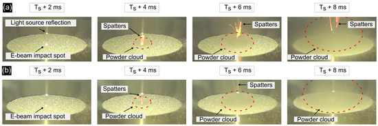
Figure 3.
Smoke experiment with Ti6Al4V. Bright spots observed prior to the Smoke indicate the rapid powder temperature increasing at the impact spot. (a) Smoke experiment initiated with a beam current of 2 mA; spatters form, accompanied by an expanding powder cloud, as indicated by the red circle. (b) Smoke experiment initiated with a beam current of 0.5 mA; a similar pattern of Smoke development is observed.
The bright spots observed in Figure 3 indicate that the powder temperature rapidly increases under the impact of the e-beam. Intriguingly, this observation seems to challenge the prevailing belief that the electrostatic charge is primarily responsible for the Smoke. Considering the small beam size used in this study, the accumulated charges should rapidly increase the electrostatic force, theoretically leading to the Smoke even before the powder attains such an elevated temperature. Moreover, when considering the experiment conducted with a beam current of 0.5 mA, the trajectory of the spatters remains strikingly similar, even though there is a 75% reduction in the input energy density and electric charge. These unexpected findings are explained in the next section.
3.2. Radiography of Smoke with CMSX-4® on MiniMelt
The radiography experiments provide a more profound understanding of Smoke development, offering enhanced temporal resolution and enabling a microscale investigation of Smoke. Figure 4 presents the Smoke phenomenon observed under a focused e-beam (205 µm FWHP). Unlike the previous studies, which focused on Smoke triggered by a charged yet unmolten powder bed [1,7,9,10], this experiment demonstrates Smoke formation subsequent to the powder’s melting, which aligns with the result from Section 3.1. The occurrence of similar Smoke development across two alloy systems with vastly different physical properties suggests that the Smoke phenomena observed in this study are likely representative of the PBF-EB process in general. Figure 4a captures the initial state of the powder hill. These images are 2D projections of the powder hill, where a darker color indicates more powder obstructing the X-ray path, resulting in less intensity at that position. It is worth noting that these images have undergone both flat and dark field corrections. Specifically, dark field images are captured with the light source turned off, representing the intrinsic noise inherent in the camera system. On the other hand, flat field images are taken without any sample in the FOV, capturing the background signal that remains consistent during the testing. These post-processing methods, as detailed in Equation (1), are employed to ensure normalized brightness levels across the entire FOV.
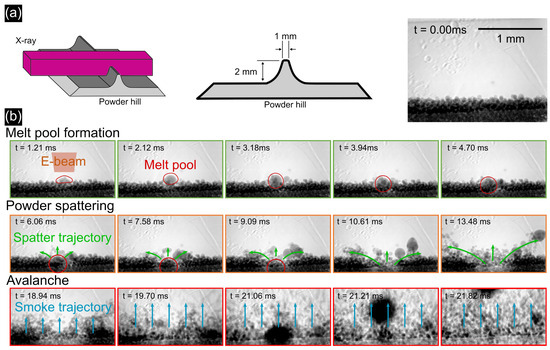
Figure 4.
Radiography of Smoke development: (a) left, illustration of imaging method; middle, dimension information about the powder hill; right, initial state of the powder hill. (b) Stage-wise Smoke development: melt pool formation (e-beam creates a melt pool), powder spattering (overheating of the melt pool and powder ejected from the surface), and Smoke avalanche (powder lifts at a significantly higher speed).
Figure 4b illustrates a three-stage Smoke development. Stage I (melt pool formation) is characterized by the formation of a melt pool under the impact of the e-beam. The pool starts forming at 1.05 ms, growing and descending with the continuous e-beam irradiation. During Stage II (powder spattering), the melt pool exits the FOV. Particles surrounding the melt pit are pushed away from the melt pool around 6.00 ms, indicating that the powder bed is not sintered. Concurrently, some powder particles coalesce into larger droplets adjacent to the growing melt pool. These particles are perceived as spatters on a larger scale. However, the characteristic spreading effect during Smoke is not yet evident. In the final Stage III (avalanche), all the powder rapidly ascends and exits the FOV at markedly higher speeds, happening within 1 ms. Interestingly, the primary melt pool is observed ascending around 20.25 ms. The progression of these stages aligns with observations from Figure 3, suggesting similar Smoke behaviors in both CMSX-4® and Ti6Al4V materials. Despite differences in powder properties and experimental conditions (e.g., process gas atmosphere), this resemblance in Smoke behavior indicates a common triggering mechanism for Smoke under a stationary e-beam.
Supplementary Material related to this article can be found in Video S1.
The stage-wise evolution of Smoke development, marked by distinct powder movement patterns, aligns with findings from other researchers who have observed similar stage-wise Smoke progression in their studies [9,10]. For example, the melt pool formation stage corresponds to the “nurture” stage observed by Wang et al., and the powder spattering and avalanche stage are summarized as the “start” stage in their work [9]. However, this study distinguished itself through its enhanced temporal and spatial resolution. For instance, finding two distinctive stages within the “start” stage indicates two different stimulation mechanisms existing within the “start” stage. This approach enables a more fundamental understanding of Smoke development.
During Stage I, the melt pool formation, the powder bed remains relatively stable, and the melt pool first appears at 1.05 ms. Notably, there is no observable powder movement prior to the formation of the melt pool. This finding is consistent with the preliminary study on the Freemelt® ONE, which indicated that the powder attains an elevated temperature before the Smoke phenomenon occurs. Furthermore, the ability to melt the powder before the avalanche phase aligns with the research conducted by Zeyu Lin et al., where they discovered that liquid-state sintering could take place before the onset of Smoke with a smaller beam size [16].
It is worth noting that the melt pool maintained a spherical shape throughout the experiment, deviating from the flat shape typically seen in PBF-EB. Given the height of the powder hill, the melt pool lacks a solid metal substrate to make contact with, as is the case in a conventional process condition. This deviation significantly influences the wetting behavior of the melt pool. The spherical shape suggests that the surface tension between the surrounding powder particles and the melt pool was significantly high. This observation is consistent with the lower process temperatures, given that the experiment was conducted over freshly applied powder hill. Additionally, it is observed that the melt pool has a spherical shape, indicating poor wetting conditions between the melt pool and the surrounding powder particles. This leads to poor thermal conductivity, creating conditions for severe evaporation subsequently.
Figure 5 illustrates the speed development of three representative particles during Stage II based on particle-tracking velocimetry, which calculates particle movement based on the distance a particle travels between frames. It should be noted that the video recording used for particle velocity analysis is a two-dimensional projection of the three-dimensional movement, meaning that the absolute speed might not be accurate as movement normal to the imaging plane is neglected. However, the trend of speed development is still very valuable. Particle A, a molten droplet with an approximate radius of 120 µm, exits the pit at an initial speed of 50 mm/s, which increases as it approaches the edge of the FOV. Its speed ceases to increase after 10.50 ms, implying that this particle exits the vapor influencing zone. Particle B, an unmolten powder particle with a radius of about 56 µm, shows a similar trend. Intriguingly, Particle C, an unmolten powder particle with a radius of about 14 µm exhibits significantly higher speeds compared to others during this stage. The higher speed of Particle C can be explained by its higher ejection angle with respect to the powder bed surface. This observation parallels the powder-spattering behavior identified in powder bed fusion–laser beam (PBF-LB) by Guo et al., where the dynamics of powder spattering under vacuum condition was studied using in situ radiography [17]. This alignment further supports the hypothesis that the drag force of metal vapor is the primary driving force behind powder movement during stage II. Given the advanced capabilities of current feature-tracking algorithms, a wide range of analyses could be performed. Nevertheless, the velocity analysis as conducted is deemed sufficient for the development of a theoretical Smoke model.
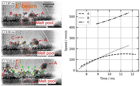
Figure 5.
Particle velocity analysis during the powder spattering. The red circles mark the moving particles, and the yellow lines indicate their trajectories. The direction of vapor pressure is depicted by green arrows. Particle A is a molten particle with a radius of approximately 120 µm, while Particles B and C are unmolten powder particles.
The transition from Stage II to Stage III occurs rapidly, as depicted in Figure 6, which displays five consecutive frames. These frames were subjected to two post-processing methods to highlight different aspects of the transition. The upper row of images has undergone contrast enhancement, outlining the overall state of the powder bed. In contrast, the lower row features differential images, created by subtracting successive frames, thereby effectively capturing the dynamic changes occurring during the transition.
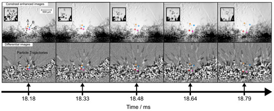
Figure 6.
Powder behavior during transition phase. Five consecutive frames from transition phase are presented, each processed using two different methods for enhanced analysis: contrast enhancement (upper row) and image subtraction (lower row). Upper row: This row of images visualizes the state of the powder bed. It highlights the movement of four particles repelling each other, color marked. This behavior is presumed to be caused by electrostatic force. Lower row: This row of images demonstrates the dynamics of powder particles. The black-and-white lines represent the trajectories of rapid moving particles. Their quantity visibly escalates over time.
The movement of four powder particles, each marked in a different color in Figure 6, exhibits a behavior not observed in the previous two stages. The contrast-enhanced images show that these particles are initially in close proximity at 18.18 ms. But within the span of the next four frames, they begin to separate from each other, suggesting the presence of a repulsive force at play. As a result, some particles are directed back to the building platform at high velocity. Numerous studies suggest that electrostatic force is the primary driver of particle movement during the Smoke phase [1,7,9,16]. Given that these four powder particles are suspended mid-air, which prevents the charge from flowing out, the repulsive force acting between them is likely electrostatic in nature. This observation suggests that the influence of electrostatic force starts approximately 18 ms after the e-beam is activated.
The differential images feature numerous elongated black-and-white lines, representing the trajectories of rapid moving powder particles. As time progresses, the increasing number of these lines suggests that more powder is being excited from the powder bed during the Smoke development phase. These lines are a result of the high-speed camera’s exposure time being insufficiently short to precisely capture the particle movements. Based on the length of these trajectories and the exposure time of the high-speed camera, these movements can be numerically analyzed. The particles exhibit an average initial velocity of 0.807 m/s, with an average acceleration of 2092 m/s2. Such rapid movements were not detected in earlier stages, reinforcing the hypothesis that the electrostatic force is also the impetus behind these particles’ acceleration. Together with the e-beam influencing area illustrated in Figure 4, it is found that some black-and-white lines originate outside of the e-beam irradiation area. This observation implies that the Smoke is not confined solely to the area influenced directly by the electron beam.
The analysis provided in the preceding paragraph indicates that electrostatic force is the initial driving force for the transition from Stage II to Stage III. The fact that this sharp movement transition happens during Stage II, where flying particles that are created prior to Smoke avalanche prove that the conventional model developed by Cordero et al. is not suitable for describing this Smoke phenomenon [7]. Therefore, this study employed a quasi-analytical model to describe the movement transition of flying particles between Stage II and Stage III.
Nevertheless, it is hard to determine whether these powder particles are directly or indirectly hit by the e-beam because the high-speed camera provides only a two-dimensional projection. Therefore, the exact mechanism of electron accumulation on these powder particles remains unclear.
To address this, a quasi-analytical model was employed to estimate the powder behavior under the direct impact of the e-beam. As illustrated in Figure 7, this model describes two spherical, electrically isolated powder particles that are symmetrically impacted by the e-beam. According to Coulomb’s law, the electrostatic force applied on both particles can be estimated with Equation (2):
In this equation, stands for the coulomb constant. and represent the time-dependent accumulated charge on the two respective particles. The variable stands for the distance between two charged particles, treating them as point charge. The particle movement is further characterized by Newton’s law, detailed in Equation (3),
where defines the mass of the powder particles, calculable from the known powder diameter, , and density, , for spherical particles. The acceleration is denoted by .
These equations are based on the assumption that electrostatic forces are the predominant forces influencing the particles. The accumulated charge on each particle is determined by Equation (4),
where denotes the charging rate. The time, , is defined as the moment when the e-beam begins irradiating the powder particles, while represents the time elapsed during the investigation. In this simulation, and are presumed to be equal for both particles. The charging rate, , is further determined using Equation (5),
This equation is defined piecewise, with the first case applying when the distance, , between the powder particles is less than the beam diameter, , indicating that the particle is within the e-beam irradiation area. The second case applies when exceeds , meaning that the particle has moved beyond the e-beam’s area, and no charging occurs. In these expressions, the term estimates the proportionate area of radiation affecting a powder particle of diameter , and denotes the beam current. Considering that only a fraction of the electrons is absorbed by the powder, with the remainder either transmitted or backscattered, the absorption coefficient is indicated by , which is combined value accounting for the absorption coefficient and the spherical shape of the powder.
The initial conditions and parameters applied in this model are detailed in Table 1. The velocities of airborne particles were numerically estimated, with the outcomes depicted in Figure 7. According to the model, the powder particles are directly hit by the e-beam, and their speed rapidly increases to 370 m/s within just 0.01 ms, exhibiting an acceleration of approximately 108 m/s2. Setting to 0.1 was intended to conservatively estimate the real absorption coefficient [18]. However, even with this underestimation, the resultant velocity calculations fall beyond the imaging limit of our high-speed camera. In addition, the rate of acceleration is five orders of magnitude greater than the value deduced from the data captured by the high-speed camera.

Table 1.
Parameters and initial conditions for the calculation of the powder particle movement.
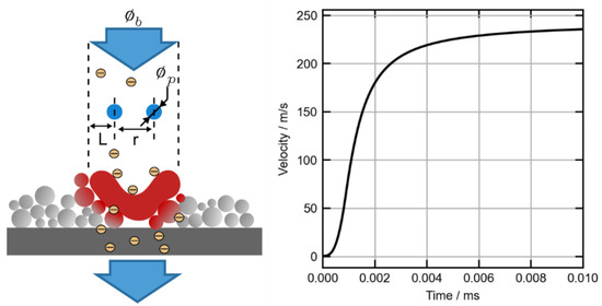
Figure 7.
Analytical model (Equations (2)–(5)) to estimate powder particle repulsion and the resulting velocity as a function of time upon direct e-beam impact. The schematic of melt pool is exaggerated for the illustration of metal evaporation.
Alternatively, airborne particles may be located outside the e-beam primary interaction zone, where charge accumulation on these particles occurs through backscattered electrons (BSEs). In this scenario, due to the spatial relationship between the powder particle and the e-beam primary interaction zone, most electrons disperse into the surrounding space, rather than colliding with the particles. To evaluate the powder movement under this condition, the charging rate, , from Equation (5) is modified to yield Equation (6).
The total amount of BSE under a beam current of is the product of and the backscattering coefficient, . The fraction of backscattered electrons arriving at the powder particle is given by the solid angle ratio between the powder particle, , and the hemisphere, . This product is further modified by weighing it with the cosine of the emission angle, α, which is the angle between the surface normal and the direction of emission.
A geometrical illustration of these parameters is provided in Figure 8a. The is estimated to be 0.29 for a nickel-based alloy under an acceleration voltage of 60 kV [18]. To better understand the influence of backscattering, the ratio of the charging rate from BSE to that from the e-beam, denoted as , is plotted in Figure 8a. This is performed as a function of the emission angle, , with the distance between the powder particle and the primary interaction zone, represented by various hemisphere radii, , also varied for comparison. Generally, this ratio is found within the range of 10−5 across various hemisphere radii. It decreases gradually as the emission angle increases. Notably, at an angle of , this ratio approaches zero, aligning with the BSE angular distribution described by Reimers [19]. Based on previous discussion, Figure 8b presents a recalculated particle velocity that aligns with the trends captured by the high-speed camera.
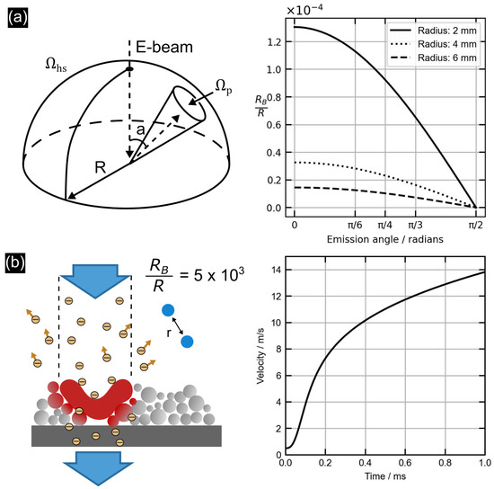
Figure 8.
Quasi-analytical simulation of powder movement due to BSE charging. (a) Left: Schematic illustrating geometrical parameters for the calculation of the backscattered electrons in the solid angle, . Right: Fraction of backscattered electrons as a function of the emission angle and the distance, , to the primary interaction zone. (b) Left: Schematic representation of powder particles charged by BSE. Right: The calculated velocity of the particles using the parameters listed in Table 1. The charging rate is set to a constant, with being 5 × 10⁻⁵.
In conclusion, due to the limited frame rate of the high-speed camera, it is challenging to definitively rule out that powder particles are directly hit by e-beam. Consequently, there are two potential scenarios for the transition phase. In the first scenario, particles are directly impacted and charged by the e-beam, resulting in such high velocities that the transition phase occurs almost instantaneously. In the second scenario, the particles are not directly hit by the beam; instead, they charged by BSE, resulting in relatively lower velocities. Nevertheless, in both scenarios, the transition phase occurs within milliseconds.
Both scenarios could trigger the transition phase during smoke evolution. Nevertheless, their likelihood differs significantly. A direct hit necessitates that the powder be located directly beneath the e-beam, while the scattering effect of the e-beam encompasses a broader area, thus increasing the probability of a BSE-induced transition phase during stationary e-beam radiation. It is crucial to note that the dimensions of the electron beam are vital in both scenarios; a larger beam diameter increases the probability of triggering the transition phase.
As a result, a model illustrating the progression of Smoke under a stationary e-beam was developed, depicted in Figure 9. Initially, the powder particles on the surface quickly heat up, as shown in Figure 9a. It is important to note that the rate of electron dissipation is sufficient to prevent the repulsion of powder particles due to electrostatic forces. Subsequently, a melt pool forms, as seen in Figure 9b. This melt pool rapidly overheats with continued e-beam exposure, leading to two major mechanisms that drive the powder bed into the avalanche phase, as illustrated in Figure 9c. The first of these is the creation of metal vapor from the overheated melt pool, which disturbs the powder bed, leading to the generation of many electrically isolated particles. It should be noted that metal vapor is just one of the factors causing such disturbances; other phenomena, like rapid thermal expansion and the melt pool’s wetting behavior, could also contribute to powder bed disturbance. The second mechanism involves the interaction of primary incident electrons with the melt pool surface, which creates BSE. As a result, these electrically isolated particles are charged either through the BSE or directly hit by the e-beam, and the system transitions to a stage where electrostatic forces between particles become the predominant influence on their movement, as depicted in Figure 9d. The repulsion among these particles causes some to fly downwards, acting like “bombs” that impact and further disrupt the powder bed, as depicted in Figure 9e. These “bomb” particles not only create additional electrically isolated particles but also transfer their electrons and momentum to neighboring particles. This sequence of events initiates more electrically isolated particles that lead the Smoke into the avalanche phase, as depicted in Figure 9f.
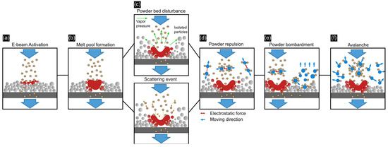
Figure 9.
A sequential illustration of Smoke development under a stationary e-beam, highlighting key mechanisms. (a) E-beam activation: Upon the e-beam activation, the top layer of powder particles rapidly heats up. Electron dissipation rates are sufficiently high to prevent charge accumulation. (b) Melt pool formation: The continuous e-beam irradiation leads to the melting of the powder bed, and electron dissipation remains adequate. (c) Powder bed disturbance and charge accumulation: Further e-beam irradiation overheats the melt pool, causing two primary effects: disturbances in the powder bed from metal vapor, creating electrically isolated particles, and backscattering of the e-beam from the melt pool surface. (d) Powder repulsion: Accumulated charge on airborne particles causes repulsion through electrostatic forces. (e) Powder bombardment: Electrostatic forces propel charged particles in various directions, some of which impact the powder bed like ‘bombs’, further isolating particles and transferring charges to neighboring particles. (f) Avalanche: The escalation of processes from steps (c) to (e) occurs, leading some particles to enter the e-beam region and triggering a rapid avalanche. The previous model highlighted two key mechanisms that contribute to the Smoke development: the generation of disturbances in the powder bed, resulting in the formation of electrically isolated particles, and the subsequent electrons accumulation on these particles. Disturbances arise from various PBF-EB process-related events, such as the metal vapor from the melt pool, thermal expansion of powder particles, the melt pool’s wetting behavior, etc. The second key mechanism is the accumulation of electrons on these isolated particles, whether through electron scattering or even direct impact.
Ye et al. observed similar Smoke patterns using a defocused beam with preheating patterns [10]. Their observations of an unstable period during Smoke development (marked by the formation of powder fume) and a subsequent catastrophic smoke event, align with the Smoke development described in previous models. Specifically, the powder fumes observed during this unstable period serve as the initial disturbances within the powder bed, leading to the formation of electrically isolated particles. These particles, once charged by the e-beam, propel the Smoke into the avalanche phase. This alignment suggests that our phenomenological model has broader applicability, encompassing both focused and defocused electron beam conditions.
This model is pivotal for understanding the fundamental mechanisms that govern particle behavior during PBF-EB process, and it is instrumental in optimizing and controlling the Smoke for various applications:
- Powder density: Heavier powder is advised to prevent powder bed disturbance.
- Powder shape: Water-atomized powder is preferable due to its irregular shape, which allows for a greater friction coefficient between powders and thereby reduces disturbances. However, this kind of powder is also reported to have a strong balling effect [20].
- Input energy: A moderate level of input energy is recommended to maintain powder bed stability. An excessive input energy facilitates the powder bed disturbance through evaporation.
- Beam size and scanning speed: If powder bed disturbance is unavoidable for certain processes, using a smaller beam size and faster scanning speed can reduce the likelihood of the e-beam directly or indirectly hitting the electrically isolated particles that is created by powder bed disturbance and thereby mitigate the avalanche phase.
- Returning time: The return time of the beam, e.g., during preheating or melting, should be sufficient for the particles to settle.
4. Conclusions
In this study, Smoke during the PBF-EB process was observed using in situ high-speed synchrotron radiography for the first time. A comprehensive model for Smoke development was developed and experimentally validated.
This model identifies two primary mechanisms responsible for Smoke development. The first mechanism involves disturbances in the powder bed that result in the formation of electrically isolated particles. This disturbance was found to be the metal vapor generated by the melt pool from the stationary e-beam Smoke experiment. The second mechanism is the accumulation of charge on these electrically isolated particles, a process that occurs via electron scattering or direct impact. This accumulation leads to the generation of a strong electrostatic force that predominantly influences particle movements. Subsequently, this initiates more electrically isolated particles, culminating in the occurrence of Smoke.
The model proposes several strategies to suppress Smoke in the PBF-EB process. The first and foremost strategy involves minimizing disturbances in the powder bed. This can be accomplished by enhancing the stability of the powder bed, for example, by using a powder with higher frictional resistance or a high weight. Additionally, mitigating the disturbances caused by the electron beam is crucial and can be addressed through careful selection and optimization of process parameters. Equally important is addressing charge accumulation on the particles. This can be managed by extending the electron beam’s return time during scanning or by reducing the e-beam’s diameter, both of which decrease the likelihood of particle charging by the e-beam. Concurrently, the use of a process gas atmosphere is recommended to facilitate the dissipation of any accumulated charge on the particles.
It is important to note that the experimental observations were made under specific conditions and with specific materials. Further research is needed to validate the model and optimization approach for other materials and process parameters. Overall, this work contributes to a better understanding of the mechanisms governing particle behavior during the Smoke and provides a foundation for optimizing and controlling the process to minimize Smoke formation and improve process stability.
Supplementary Materials
The following supporting information can be downloaded at https://www.mdpi.com/article/10.3390/jmmp8030103/s1. Video S1: Smoke phenomenon recorded using x-radiography.
Author Contributions
Conceptualization, J.Y.; methodology, J.Y., N.S. and P.B.; software, J.Y., N.S. and P.B.; validation, J.Y., N.S. and P.B.; formal analysis, J.Y. and N.S.; investigation, J.Y., N.S. and P.B.; resources, G.L. and C.K.; data curation, J.Y., N.S. and P.B.; writing—original draft preparation, J.Y.; writing—review and editing, J.Y., N.S. and C.K.; visualization, J.Y. and N.S.; supervision, G.L. and C.K.; project administration, G.L. and C.K.; funding acquisition, G.L. and C.K. All authors have read and agreed to the published version of the manuscript.
Funding
The financial support provided by the German Research Foundation (DFG) for the project (FU 1283/2-1) is gratefully acknowledged. Additionally, this work was performed as part of the project “Real-time tracking of electron beam additive manufacturing”, Grant No. 201906068, funded by the Swedish Research Council (VR) and the Bundesministerium für Bildung und Forschung (BMBF) via the Röntgen-Ångström Cluster (RÅC). The authors acknowledge DESY (Hamburg, Germany), a member of the Helmholtz Association HGF, for the provision of the synchrotron infrastructure on beamline P61A, as well as Hereon for the experimental facilities at P61A. Beamtime was allocated for Proposal No. II-20220735 EC.
Data Availability Statement
The original contributions presented in the study are included in the article/Supplementary Materials. Further inquiries can be directed to the corresponding authors.
Acknowledgments
Valuable assistance in the development of a quasi-analytical model, offered by Jakob Renner, is sincerely appreciated.
Conflicts of Interest
The authors declare no conflict of interest.
References
- Eschey, C.; Lutzmann, S.; Zaeh, M.F. Examination of the powder spreading effect in Electron Beam Melting (EBM). In 2006 International Solid Freeform Fabrication Symposium; University of Texas at Austin: Austin, TX, USA, 2009; p. 12. [Google Scholar] [CrossRef]
- Sigl, M.; Lutzmann, S.; Zaeh, M.F. Transient Physical Effects in Electron Beam Sintering: Smoke possible Reasons. In 2006 International Solid Freeform Fabrication Symposium; University of Texas at Austin: Austin, TX, USA, 2006. [Google Scholar] [CrossRef]
- Fu, Z.; Körner, C. Actual state-of-the-art of electron beam powder bed fusion. Eur. J. Mater. 2022, 2, 54–116. [Google Scholar] [CrossRef]
- Ljungblad, U. Radiation Method for Additive Manufacturing. U.S. Patent US11534963B2, 27 December 2022. Available online: https://patents.google.com/patent/US11534963B2/en?oq=us+11534963 (accessed on 4 August 2023).
- Van Den Berg, J.A.; Hussey, M.J.; Richardson, W.T.; Laidler, I. Additive Layer Manufacture Using Charged Particle Beams. U.S. Patent US10879039B2, 29 December 2020. Available online: https://patents.google.com/patent/US10879039B2/en?oq=US10879039B2 (accessed on 4 August 2023).
- Chiba, A.; Daino, Y.; Aoyagi, K.; Yamanaka, K. Smoke Suppression in Electron Beam Melting of Inconel 718 Alloy Powder Based on Insulator–Metal Transition of Surface Oxide Film by Mechanical Stimulation. Materials 2021, 14, 4662. [Google Scholar] [CrossRef] [PubMed]
- Cordero, Z.C.; Meyer, H.M.; Nandwana, P.; Dehoff, R.R. Powder bed charging during electron-beam additive manufacturing. Acta Mater. 2017, 124, 437–445. [Google Scholar] [CrossRef]
- Yim, S.; Aoyagi, K.; Yanagihara, K.; Bian, H.; Chiba, A. Effect of mechanical ball milling on the electrical and powder bed properties of gas-atomized Ti–48Al–2Cr–2Nb and elucidation of the smoke mechanism in the powder bed fusion electron beam melting process. J. Mater. Sci. Technol. 2023, 137, 36–55. [Google Scholar] [CrossRef]
- Wang, D.; Zhao, D.; Liang, X.; Li, X.; Lin, F. Multiple stages of smoking phenomenon in electron beam powder bed fusion process. Addit. Manuf. 2023, 66, 103434. [Google Scholar] [CrossRef]
- Ye, J.; Renner, J.; Körner, C.; Fu, Z. Electron-optical observation of smoke evolution during electron beam powder bed fusion. Addit. Manuf. 2023, 70, 103578. [Google Scholar] [CrossRef]
- König, H.-H.; Semjatov, N.; Spartacus, G.; Bidola, P.; Ioannidou, C.; Ye, J.; Renner, J.; Lienert, U.; Faria, G.A.; Wahlmann, B.; et al. MiniMelt: An instrument for real-time tracking of electron beam additive manufacturing using synchrotron X-ray techniques. Rev. Sci. Instrum. 2023, 94, 125103. [Google Scholar] [CrossRef] [PubMed]
- Farla, R.; Bhat, S.; Sonntag, S.; Chanyshev, A.; Ma, S.; Ishii, T.; Liu, Z.; Neri, A.; Nishiyama, N.; Faria, G.A.; et al. Extreme conditions research using the large-volume press at the P61B endstation, PETRA III. J. Synchrotron Radiat. 2022, 29, 409–423. [Google Scholar] [CrossRef] [PubMed]
- Leung, C.L.A.; Marussi, S.; Atwood, R.C.; Towrie, M.; Withers, P.J.; Lee, P.D. In situ X-ray imaging of defect and molten pool dynamics in laser additive manufacturing. Nat. Commun. 2018, 9, 1355. [Google Scholar] [CrossRef] [PubMed]
- Parab, N.D.; Zhao, C.; Cunningham, R.; Escano, L.I.; Fezzaa, K.; Everhart, W.; Rollett, A.D.; Chen, L.; Sun, T. Ultrafast X-ray imaging of laser–metal additive manufacturing processes. J. Synchrotron Radiat. 2018, 25, 1467–1477. [Google Scholar] [CrossRef] [PubMed]
- Ioannidou, C.; König, H.-H.; Semjatov, N.; Ackelid, U.; Staron, P.; Körner, C.; Hedström, P.; Lindwall, G. In-situ synchrotron X-ray analysis of metal Additive Manufacturing: Current state, opportunities and challenges. Mater. Des. 2022, 219, 110790. [Google Scholar] [CrossRef]
- Lin, Z.; Dadbakhsh, S.; Rashid, A. Developing processing windows for powder pre-heating in electron beam melting. J. Manuf. Process. 2022, 83, 180–191. [Google Scholar] [CrossRef]
- Guo, Q.; Zhao, C.; Escano, L.I.; Young, Z.; Xiong, L.; Fezzaa, K.; Everhart, W.; Brown, B.; Sun, T.; Chen, L. Transient dynamics of powder spattering in laser powder bed fusion additive manufacturing process revealed by in-situ high-speed high-energy X-ray imaging. Acta Mater. 2018, 151, 169–180. [Google Scholar] [CrossRef]
- Neubert, G.; Rogaschewski, S. Backscattering coefficient measurements of 15 to 60 keV electrons for solids at various angles of incidence. Phys. Status Solidi 1980, 59, 35–41. [Google Scholar] [CrossRef]
- Reimer, L. Scanning Electron Microscopy: Physics of Image Formation and Microanalysis; Springer Series in Optical Sciences; Springer: Berlin/Heidelberg, Germany, 1998. [Google Scholar] [CrossRef]
- Qi, H.B.; Yan, Y.N.; Lin, F.; He, W.; Zhang, R.J. Direct metal part forming of 316L stainless steel powder by electron beam selective melting. Proc. Inst. Mech. Eng. Part B J. Eng. Manuf. 2006, 220, 1845–1853. [Google Scholar] [CrossRef]
Disclaimer/Publisher’s Note: The statements, opinions and data contained in all publications are solely those of the individual author(s) and contributor(s) and not of MDPI and/or the editor(s). MDPI and/or the editor(s) disclaim responsibility for any injury to people or property resulting from any ideas, methods, instructions or products referred to in the content. |
© 2024 by the authors. Licensee MDPI, Basel, Switzerland. This article is an open access article distributed under the terms and conditions of the Creative Commons Attribution (CC BY) license (https://creativecommons.org/licenses/by/4.0/).