
Electrospun Si and Si/C Fiber Anodes for Li-Ion Batteries


Department of Chemical and Biomolecular Engineering, Vanderbilt University, Nashville, TN 37235, USA
*
Author to whom correspondence should be addressed.
Batteries 2023, 9(12), 569; https://doi.org/10.3390/batteries9120569
Submission received: 30 October 2023
/
Revised: 14 November 2023
/
Accepted: 23 November 2023
/
Published: 26 November 2023
(This article belongs to the Section Battery Materials and Interfaces: Anode, Cathode, Separators and Electrolytes or Others)
Abstract
:Due to structural changes in silicon during lithiation/delithiation, most Li-ion battery anodes containing silicon show rapid gravimetric capacity fade upon charge/discharge cycling. Herein, we report on a new Si powder anode in the form of electrospun fibers with only poly(acrylic acid) (PAA) binder and no electrically conductive carbon. The performance of this anode was contrasted to a fiber mat composed of Si powder, PAA binder, and a small amount of carbon powder. Fiber mat electrodes were evaluated in half-cells with a Li metal counter/reference electrode. Without the addition of conductive carbon, a stable capacity of about 1500 mAh/g (normalized to the total weight of the anode) was obtained at 1C for 50 charge/discharge cycles when the areal loading of silicon was 0.30 mgSi/cm2, whereas a capacity of 800 mAh/g was obtained when the Si loading was increased to ~1.0 mgSi/cm2. On a Si weight basis, these capacities correspond to >3500 mAh/gSi. The capacities were significantly higher than those found with a slurry-cast powdered Si anode with PAA binder. There was no change in fiber anode performance (gravimetric capacity and constant capacity with cycling) when a small amount of electrically conductive carbon was added to the electrospun fiber anodes when the Si loading was ≤1.0 mgSi/cm2.
1. Introduction
Since their introduction in 1991, lithium-ion batteries (LIBs) have improved in performance with a parallel growth in sales. Today, they dominate the portable electronics and electric vehicle markets [1,2,3,4]. Current lithium-ion batteries contain a lithium metal oxide cathode, a graphite anode, and a liquid electrolyte [5,6]. The intrinsic specific energy and energy density of such batteries (270 Wh/kg and 650 Wh/L, respectively) are significantly below the requirements of future automotive markets [7,8,9]. Silicon as the anode material in LIBs is an attractive alternative to graphite [10,11,12,13]. It has a very high theoretical gravimetric capacity of 3579 mAh/g (for Li15Si4), a low lithiation potential (<0.5 V vs. Li/Li+), and is low in cost due to its abundance in nature. A typical Si anode contains a mixture of Si (as the primary lithiation host), carbon powder for electrical conduction, and a polymer binder. Short cycle life, however, is an issue in such electrodes due to severe volume changes of Si and the resultant internal stresses that are generated during lithiation/delithiation (expansion of almost 360% from Si to Li4.4Si) [14,15,16,17]. Si/carbon electrode failure occurs by (i) continuous pulverization of Si and carbon particles during recurrent charging/discharging, which destroys the structural integrity of the electrode, (ii) interfacial stresses which create disconnects between the collector and electrode, and (iii) the consumption/reaction of lithium ions during repeated formation, breakage, and reformation of the solid electrolyte interphase (SEI) leading to Li+ ion depletion [18,19]. Common strategies to combat these unwanted events have focused mainly on the use of composites to either accommodate Si swelling or to shield Si from reaction with the electrolyte. Wang et al. generated one such composite by growing 3D multi-layer graphene sheets in situ on nano-silicon particles [20]. The silicon particles were coated with nickel, which acted as a catalytic layer for graphene growth. The nickel was then etched, leaving behind particles coated with carbon, which served as a buffer to negate volume expansion and limit interactions of the silicon with electrolyte. Their anode was able to achieve a capacity of 1909 mAh/g after 100 cycle (53% retention) at a low charge/discharge rate of 0.22 A/g [20]. In another study, Jang et al. chose to focus on the polymer binder as a method of ameliorating the severe expansion of silicon by using a self-healing poly(acrylic acid) (PAA) binder functionalized with diarylbibenzofuranone (DABBF) [21]. This self-healing was attributed to reversible C–C bonding and debonding of dynamic carbon radicals, which stabilized the silicon and improved adhesion. Anodes made with the DABBF-functionalized PAA achieved an initial coulombic efficiency of 77.89% and maintained a capacity of 1774 mAh/g after 500 cycles at 0.5 C (~48% retention) and 1694 mAh/g after 300 cycles at a C-rate of 1.0 (~47% retention) [21], but the anode mass loading was low at ~0.5 mgSi/cm2. To mitigate the volume expansion of silicon, some studies focused on creating ample void space in the electrode to accommodate volume expansion. A yolk-shell structure was made by Zhang et al., in which a shell of carbon/SiO2 was grown around silicon particles [22]. Additionally, carbon nanotubes were included in the core of the shell to maintain electrical contact with the silicon particles. These anodes maintained an areal capacity of 2.4 mAh/cm2 after 100 cycles at 0.6 mA/cm2 in half-cells [22]. In another study, Wang et al. fabricated anodes using a Si/C “onion-like” composite structure that was made by dispersing silicon nanoparticles in pyridine before injection pyrolysis [23]. The resulting structure was carbon-coated silicon particles with an internal void space. These porous, Si/C anodes achieved a capacity of 1390 mAh/g after 400 cycles at 0.2 A/g (66% capacity retention). From these and other studies in the literature, it appears that the strategy of using nanostructured Si anodes e.g., Si nanoparticle/polymer composites, Si thin films, Si nanowires, or core/shell structures, although promising, still falls short of achieving high areal and volumetric capacities while retaining high capacity upon cycling.
Another approach for generating new battery electrode architectures is nanofiber electrospinning. Over the last decade, fiber mat materials, where the fibers contain particles and a polymer binder, have been prepared and characterized for both fuel cell [24,25] and LIB [26,27,28,29] electrodes with promising results. Self et al., for example, showed that a freestanding nanofiber particle/polymer anode containing Si nanoparticles, poly(acrylic acid) and carbon black (Si/PAA/C) worked well in a Li battery coin cell [27]. High areal and volumetric capacities (e.g., 3.5 mAh/cm2 and 750 mAh/cm3, respectively) were observed for electrospun and compacted Si/PAA/C fiber mat anodes in half-cell tests and a specific energy density of 270 Wh/kg was found in full cell experiments with an electrospun LiCoO2/C fiber cathode. The surprisingly good performance of the particle/polymer fiber mat anodes was attributed to (i) a high electrolyte–electrode interfacial area and short transport pathways for Li+ from the electrolyte to active Si particles due to the submicron diameter of the electrospun fibers, and (ii) inter- and intra-fiber porosity, which facilitate the penetration of the electrolyte into the fiber mat and into individual fibers while providing void-volume to accommodate Si expansion.
The present work is an extension of the electrospun anode research by Self and co-workers in [27]. Herein, we describe the fabrication and half-cell characterization of electrospun Si-based fiber anodes with no carbon (Si/PAA) and with very low (≤12 wt.%) carbon content (Si/PAA/C). Some electrodes worked well in coin cell tests with a Li metal counter electrode, with better gravimetric and volumetric Li-ion storage capacity retention than prior studies. The carbon-free electrode work is the first of its kind and represents an entirely new way of incorporating Si-containing fibers into Li-ion batteries.
2. Materials and Methods
2.1. Electrospinning Si/PAA and Si/PAA/C Nanofiber Mats
A single needle spinneret electrospinning apparatus with a rotating and oscillating drum collector was employed to fabricate fiber mat anodes (Figure 1) [25,26]. Fiber mat Si/poly(acrylic acid) (PAA) anodes were fabricated from solutions containing 9 wt.% Si nanoparticles (50–70 nm particle size, from US Research Nanomaterials), and PAA binder in a 57/43 wt.% isopropanol (IPA)/methanol (MeOH) solvent mixture, where such solutions produced fibers with Si/PAA weight ratio compositions ranging from 58/42 to 67/33. As an example, one electrospinning ink consisted of 0.36 g Si, 0.24 g PAA, 2.0 g IPA, and 1.5 g MeOH.
A series of Si/PAA/C fibers with 40 wt.% PAA, 3–12 wt.% C and the remaining wt.% Si were prepared from Si nanoparticles, PAA binder, and Vulcan XC-72R carbon in a 57/43 wt.% IPA/MeOH solvent mixture. Thus, one electrospinning ink consisted of 0.35 g Si, 0.24 g PAA, 0.018 g C, 2.0 g IPA, and 1.5 g MeOH. It should be noted that the carbon content in these Si fibers is significantly less than that in a prior fiber anode paper [27].
All electrospinning solutions were sonicated for 30 min and then mechanically stirred for 24 h. Electrospinning was performed at room temperature and 20% relative humidity, where the collector-to-spinneret distance was 8 cm, the bias voltage was 8 kV, and the solution flowrate was 0.75 mL/h.
Slurry anodes were prepared from solutions containing 40 wt.% PAA with different amounts of Si nanoparticles in a 50/50 wt.% IPA/MeOH solvent mixture. Sufficient solution amount was painted onto a Cu foil current collector to achieve Si loadings of 0.43, 0.50, 1.22, and 1.57 mgSi/cm2. For electrospun mats, sufficient mat material was laid onto a Cu foil current collector to achieve a Si loading between 0.29 and 1.00 mgSi/cm2. As-spun mats or slurry-cast anodes, supported on Cu foil, were dried overnight under vacuum at 70 °C. Fiber mat anodes were then exposed to DMF vapor for up to 1 h to weld fibers at intersecting nodes. Mats were compacted for 1 min at 57 MPa using a hydraulic press and then heated at 120 °C under vacuum for 1 h to remove residual solvent. Fiber- and slurry-cast anode discs, 1 cm in diameter, were cut, weighed, and reheated at 120 °C under vacuum for an additional 1 h before transferring to a glovebox for half-cell assembly.
2.2. Half-Cell Testing
Electrospun mats (single-fiber Si/PAA and Si/PAA/C) and slurry-cast anodes were characterized in half-cell experiments. The objective was to understand the effect of cathode morphology (fibers vs. slurry), Si loading, and the presence of carbon particles in Si fibers on anode performance.
CR2032 half-cells were assembled in a glovebox under argon atmosphere. Either fiber mats or slurry-cast electrodes (circular disks 1 cm in diameter) served as the working electrode. A Li metal disk was used as the counter/reference electrode with 1.2 M LiPF6 in ethylene carbonate/diethyl carbonate 30/70 vol/vol mixture (BASF) as electrolyte. Fluoroethylene carbonate (30 wt.%, BASF) was added to the electrolyte to stabilize the SEI layer, as has been reported in various studies on Si-based anodes [30]. Two Celgard 2500 disks soaked with electrolyte were used as a separator. Cells were crimped at 1000 psi and left overnight to equilibrate before testing. Galvanostatic charge/discharge experiments were carried out where the cells were polarized between 0.015–1.5 V vs. Li/Li+ at either 0.1C or 1C, employing an 8-channel tester (5 V/1 mA, MTI). Theoretical capacities of 3600 mAh/g for Si and 372 mAh/g for carbon were assumed for C-rate calculations. The half-cell gravimetric capacity was normalized to either the total weight of a composite anode, which included the weight of Si, C, and PAA or to the weight of Si only.
3. Results
3.1. Electrospun Anodes
As representative examples, top-down SEM images of electrospun Si/PAA mat containing 40 wt.% PAA are shown in Figure 2a (the as-spun fiber mat) and Figure 2b (the same fiber mat after inter-fiber welding and mat compaction). Well-formed fibers were produced with no beads or bead-on-fiber defects and a near-uniform fiber diameter. Using ImageJ analysis of digitized SEMs, the mean fiber diameter of the mats in Figure 2a was estimated to be 700 nm, with a mat porosity of 92%. As can be seen in Figure 2b, the fiber mat morphology is retained after mat compaction and fiber welding, where the porosity decreased significantly to approximately 45%. Fiber mats with a higher or lower PAA content looked similar to those in Figure 2.
The results of cycling experiments with four electrospun and four slurry-cast anodes are shown in Figure 3a and Figure 3b, respectively. The electrodes, which differ in Si loading and PAA content, contained no conductive carbon. Coin cells underwent 50 charge/discharge cycles at 1C after preconditioning for 5 cycles at 0.1C. For all half-cells, there was an initial rise in capacity during the break-in period and a drop in capacity when the charge/discharge rate was increased from 0.1C to 1C. This behavior is consistent with prior Si anode battery experiments, where higher C-rates lead to lower capacity due to greater activation and IR losses [26,27]. Despite the absence of conductive carbon, all of the electrodes were successfully cycled, but the fiber mat anodes exhibited higher gravimetric capacities than slurry anodes. For example, a fiber mat anode coin cell with a Si areal loading of 0.35 mgSi/cm2 showed stable cycling at 1100 mAh/g, (curve 2 in Figure 3a), whereas the gravimetric capacity of a slurry-cast powder Si anode at an areal loading of 0.43 mgSi/cm2 was only 800 mAh/g. (curve 1 in Figure 3b). Additionally, all of the fiber mat anode coin cells (for areal loadings up to 1.0 mgSi/cm2) showed stable cycling, whereas slurry-cast anode cells exhibited long-term stable cycling only for Si areal loadings of 0.43 and 0.5 mgSi/cm2. In particular, the two slurry anode cells with an Si loading exceeding 1.0 mgSi/cm2 showed significant capacity fade with a terminal discharge capacity of 250 mAh/g and 100 mAh/g for loading of 1.22 and 1.57 mgSi/cm2, respectively, after 50 cycles.
The stabilized effective gravimetric capacity of fiber mat and slurry anodes (curves 1–4 in Figure 3a and curves 1 and 2 in Figure 3b) was found to be inversely proportional to Si areal loading, indicating that some fraction of the anode, presumably furthest from the separator, was not undergoing lithiation/delithiation (the entire anode weight was used when calculating gravimetric capacity whereas only a portion of the Si was electrochemically active). There was no effort in the present study to measure the thickness of the prepared anodes and then minimize or standardize the thickness for a given areal loading, nor was there any attempt to maintain a constant anode porosity as the areal capacity was increased. Such experiments, which are planned for the future, could shed light on how electrolyte penetration (related to porosity) and the electrical and ionic resistance of the anode (related to anode thickness) impact gravimetric capacity. Although high areal loadings (i.e., >1.0 mgSi/cm2) were not examined in fiber mat anodes, the results in Figure 3 highlight how the fibrous morphology aids in achieving stable, high gravimetric capacity cycling by allowing for fast Li+ ion diffusion to/from Si particles and by accommodating Si particle swelling and shrinkage without damaging the overall morphology of the anode.
A summary of areal and gravimetric capacities as a function of PAA content and Si areal loading for Si/PAA nanofiber anode coin cells investigated in this study after 50 charge/discharge cycles is shown in Figure 4. The areal loading of Si varied from about 0.25 to 1.0 mgSi/cm2 and the PAA content varied from about 36 wt.% to 42 wt.%. An areal capacity greater than 1.0 mAh/cm2 was achieved with some coin cells, although there was no clear functional dependence of areal capacity on PAA content or Si areal loading. Again, the fiber mat anode thickness and porosity may be playing a role here. Some duplicate anode tests were carried out with reasonably good results, but further studies are needed to better assess anode reproducibility and how inherent variations in fiber mat morphology from one electrospinning run to another affect anode performance. The difference in gravimetric capacity for curves 3 and 4 in Figure 3a (anodes with essentially the same Si loading) suggest that anode fiber mat reproducibility needs to be further examined in some detail. At the same time, it is important to note that the fiber morphology is not expected to be the same as the composition of the fiber spinning solution changes. The goal of an electrospinning experiment is to find the proper conditions that lead to well-formed fibers with minimal/no beads or bead-on-fiber defects. There was no effort, for example, to maintain the exact same fiber diameter when the PAA binder content in a spinning solution was increased. Thus, it is not yet known if/how the mean fiber diameter and anode thickness/porosity after fiber welding and mat compaction vary from separate duplicate fiber mats or when the electrospinning solution composition (Si and PAA contents) is changed to accommodate a different overall anode fiber composition. Nevertheless, the results in Figure 3a and Figure 4 show that Si/PAA fiber mat anodes with no conductive carbon can function well in a Li-ion battery with a high gravimetric capacity and a moderately high areal capacity.
To better visualize the effect of Si loading on the performance of electrospun and slurry anodes, gravimetric capacity is plotted versus Si areal loading after 5 charge/discharge cycles at 0.1C (Figure 5a) and after an additional 50 charge/discharge cycles at 1C (Figure 5b). At infinitely low anode thickness (the linear dotted line extrapolation in Figure 5 to zero Si nanoparticle loading), the gravimetric capacity approaches 2600 mAh/g at 0.1C, and 2000 mAh/g at 1C. Using 2600 mAh/g and a linear mixing rule to account for the presence of PAA (33–42 wt.%) and taking a mean value of 37.5 wt.% for PAA, the lithiation capacity of Si nanoparticles was found to be 4160 mAh/g, somewhat higher than the theoretical Si lithiation capacity of 3579 mAh/g. At 1C, however, the extrapolated (zero loading) Si capacity was only 3200 mAh/g. Thus, it can be concluded that for low charge/discharge rates and low Si areal loadings, nearly all available silicon in a fiber mat anode or slurry anode is utilized, whereas at higher C-rates, a significant IR drop renders part of the anode inactive, even at low areal loadings.
3.2. Electrospun Si/PAA/C Anodes
As a follow-on to the single fiber Si/PAA anode experiments, anodes were also prepared with fibers containing Si, PAA, and a small amount of carbon. It was hypothesized that the addition of a small amount of an electronic conductor (3–12 wt.% carbon black), to electrospun fibers would increase the capacity of thicker anodes, as compared to those composed of only Si and PAA. A series of single fiber anode mats were prepared with different carbon contents and different Si areal loadings, ranging from 0.62 to 1.39 mgSi/cm2. Coin cells with these anode fiber mats underwent the same break-in procedure as carbon-free anodes, i.e., 5 cycles at 0.1C. A summary of the anode compositions and resultant areal capacities for five coin cells after 50 cycles is presented in Table 1, and gravimetric capacity (after break-in) vs. cycle number plots for five cells are shown in Figure 6. The initial gravimetric capacity of all five anodes shown in Figure 6 is much lower than expected based on the fiber composition, e.g., 1755 mAh/gSi and 2049 mAh/gSi for anodes containing 3 wt.% and 12 wt.% carbon, respectively, indicating that relatively small additions of carbon to Si fiber anodes is insufficient to establish a well-conducting percolating (electronically conductive) network.
Overall, it can be concluded that the presence of a small amount of conductive carbon to a Si/PAA fiber anode at a Si areal loading of ~1.0 mgSi/cm2 had no real effect on long-term (55 cycles) effective gravimetric capacity (comparing curve 1 in Figure 6 with the average of curves 3 and 4 in Figure 3a).
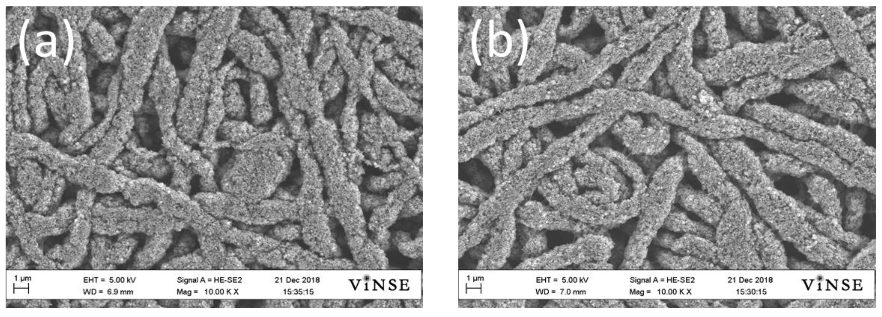
Fiber mat anodes in Figure 6 with a Si loading of 0.97 mgSi/cm2 and 0.70 mgSi/cm2 exhibited stable cycling performance for carbon contents of 3 wt.% and 6 wt.%, respectively. The former also had the highest areal capacity after 50 charge/discharge cycles (1.38 mAh/cm2) of all the anodes examined in this study. A comparison of the long-term capacity of anode 1 in Figure 7 (0.97 mgSi/cm2 with 3 wt.% C) with the average capacity of Si/PAA anodes 3 and 4 in Figure 3a (0.95 and 1.0 mgSi/cm2 with 0 wt.% C) shows no improvement in gravimetric capacity with carbon addition. There was no direct correlation between carbon content and cycle stability nor was there a correlation between cycle stability and total anode solids content (weight of PAA + Si + C). There was no significant difference in fiber morphology when carbon powder was added to the Si/PAA electrospinning solution nor did the fiber appearance change with varying carbon content. The similarity in fiber morphology with different amounts of carbon is shown by the top-down SEM images of welded/compacted anode fiber mats containing 6 wt.% carbon (0.92 mgSi/cm2) and 12 wt.% carbon (0.62 mgSi/cm2) in Figure 7. The significant capacity fade shown in Figure 6 for fiber anode 5 and for slurry anodes 3 and 4 in Figure 3b provide some evidence that the over-riding deleterious effect of high Si loading (loadings > 1.0 mgSi/cm2) on anode durability dominates over both morphology (slurry or fiber anodes) and composition (anodes with or without carbon). The precise cause for such anode performance deterioration will require further study.
4. Conclusions
A new fiber-based anode architecture based on electrospun Si/PAA fibers and on Si/C/PAA fibers with a low carbon content has been investigated in Li-ion coin cells. Without the addition of conductive carbon, a stable effective capacity of about 1500 mAh/g was obtained at 1C after 50 cycles when the Si areal loading was 0.3 mgSi/cm2 and a stable capacity of 800 mAh/g was achieved when the Si loading was 0.95–1.0 mgSi/cm2. Stable charge/discharge cycling was also observed with slurry-cast Si/PAA anodes, but the capacities were significantly lower than the fiber mat anodes. This study demonstrates for the first time that Si nanoparticle anodes can undergo lithiation/delithiation in the absence of electrically conductive carbon. Attempts to increase the gravimetric capacity at a Si loading greater than 1.0 mgSi/cm2 by the addition of carbon nanoparticles (at 9 and 12 wt.%) resulted in capacity fade. The addition of 3 wt.% or 6 wt.% carbon to Si/PAA fiber mat anodes at Si areal loadings ≤ 1.0 mgSi/cm2 had no effect on anode performance. Future work will focus on increasing the Si areal loading by increasing the Si/PAA weight ratio of electropsun fibers while maintaining inter-fiber and/or intra-fiber porosity to accommodate Si particle volume changes during charge/discharge cycling.
Author Contributions
Conceptualization: P.N.P.; methodology, A.N.M. and R.W.; validation, A.N.M. and R.W.; formal analysis, A.N.M., R.W. and P.N.P.; writing–original draft preparation, A.N.M. and R.W.; writing–review and editing, J.W. and P.N.P.; supervision, P.N.P.; project administration, P.N.P.; funding acquisition, P.N.P. All authors have read and agreed to the published version of the manuscript.
Funding
This work was funded in part by the United States Department of Energy, Vehicle Technologies Office, Grant No. DE-EE0007215.
Data Availability Statement
The data presented in this study are available on request from the corresponding author. The data are not publicly available due to privacy restrictions.
Conflicts of Interest
The authors declare no conflict of interest.
References
- Thackeray, M.M.; Wolverton, C.; Isaacs, E.D. Electrical Energy Storage for Transportation-Approaching the Limits of, and Going beyond, Lithium-Ion Batteries. Energy Environ. Sci. 2012, 5, 7854–7863. [Google Scholar] [CrossRef]
- Wu, F.; Maier, J.; Yu, Y. Guidelines and Trends for Next-Generation Rechargeable Lithium and Lithium-Ion Batteries. Chem. Soc. Rev. 2020, 49, 1569–1614. [Google Scholar] [CrossRef] [PubMed]
- Xu, J.; Cai, X.; Cai, S.; Shao, Y.; Hu, C.; Lu, S.; Ding, S. High-Energy Lithium-Ion Batteries: Recent Progress and a Promising Future in Applications. Energy Environ. Mater. 2023, 6, e12450. [Google Scholar] [CrossRef]
- Casimir, A.; Zhang, H.; Ogoke, O.; Amine, J.C.; Lu, J.; Wu, G. Silicon-Based Anodes for Lithium-Ion Batteries: Effectiveness of Materials Synthesis and Electrode Preparation. Nano Energy 2016, 27, 359–376. [Google Scholar] [CrossRef]
- Zhang, H.; Yang, Y.; Ren, D.; Wang, L.; He, X. Graphite as Anode Materials: Fundamental Mechanism, Recent Progress and Advances. Energy Storage Mater. 2021, 36, 147–170. [Google Scholar] [CrossRef]
- Kim, T.; Song, W.; Son, D.Y.; Ono, L.K.; Qi, Y. Lithium-Ion Batteries: Outlook on Present, Future, and Hybridized Technologies. J. Mater. Chem. A 2019, 7, 2942–2964. [Google Scholar] [CrossRef]
- Wang, C.Y.; Liu, T.; Yang, X.G.; Ge, S.; Stanley, N.V.; Rountree, E.S.; Leng, Y.; McCarthy, B.D. Fast Charging of Energy-Dense Lithium-Ion Batteries. Nature 2022, 611, 485–490. [Google Scholar] [CrossRef]
- Frith, J.T.; Lacey, M.J.; Ulissi, U. A Non-Academic Perspective on the Future of Lithium-Based Batteries. Nat. Commun. 2023, 14, 420. [Google Scholar] [CrossRef]
- Feng, L.; Li, M.; Liu, W.; Kashkooli, A.G.; Xiao, X.; Cai, M.; Chen, Z. Silicon-Based Anodes for Lithium-Ion Batteries: From Fundamentals to Practical Applications. Small 2018, 14, 1702737. [Google Scholar] [CrossRef]
- Huang, G.; Han, J.; Lu, Z.; Wei, D.; Kashani, H.; Watanbe, K.; Chen, M. Ultrastable Silicon Anode by Three-Dimensional Nanoarchitecture Design. ACS Nano 2020, 14, 4374–4382. [Google Scholar] [CrossRef]
- Chae, S.; Choi, S.H.; Kim, N.; Sung, J.; Cho, J. Integration of Graphite and Silicon Anodes for the Commercialization of High-Energy Lithium-Ion Batteries. Angew. Chem. Int. Ed. 2020, 59, 110. [Google Scholar] [CrossRef] [PubMed]
- Sun, L.; Liu, Y.; Shao, R.; Wu, J.; Jiang, R.; Jin, Z. Recent Progress and Future Perspective on Practical Silicon Anode-Based Lithium Ion Batteries. Energy Storage Mater. 2022, 46, 482–502. [Google Scholar] [CrossRef]
- Gu, L.; Han, J.; Chen, M.; Zhou, W.; Wang, X.; Xu, M.; Lin, H.; Liu, H.; Chen, H.; Chen, J.; et al. Enabling Robust Structural and Interfacial Stability of Micron-Si Anode Toward High-Performance Liquid and Solid-State Lithium-Ion Batteries. Energy Storage Mater. 2022, 52, 547–561. [Google Scholar] [CrossRef]
- Li, P.; Hwang, J.Y.; Sun, Y.K. Nano/Microstructured Silicon-Graphite Composite Anode for High-Energy-Density Li-Ion Battery. ACS Nano 2019, 13, 2624–2633. [Google Scholar] [CrossRef] [PubMed]
- Jiang, C.; Xiang, L.; Miao, S.; Shi, L.; Xie, D.; Yan, J.; Zheng, Z.; Zhang, X.; Tang, Y. Flexible Interface Design for Stress Regulation of a Silicon Anode toward Highly Stable Dual-Ion Batteries. Adv Mater. 2020, 32, 1908470. [Google Scholar] [CrossRef] [PubMed]
- Wu, H.; Cui, Y. Designing Nanostructured Si Anodes for High Energy Lithium Ion Batteries. Nano Today 2012, 7, 414–429. [Google Scholar] [CrossRef]
- Wang, F.; Ruan, T.; Gao, T.; Song, R.; Jin, F.; Zhou, Y.; Wang, D.; Liu, H.; Dou, S. Construction of Structure-Tunable Si@Void@C Anode Materials for Lithium-Ion Batteries through Controlling the Growth Kinetics of Resin. ACS Nano 2019, 13, 12219–12229. [Google Scholar] [CrossRef]
- Li, J.Y.; Xu, Q.; Li, G.; Yin, Y.X.; Wan, L.J.; Guo, Y.G. Research Progress Regarding Si-Based Anode Materials Towards Practical Application in High Energy Density Li-Ion Batteries. Mater. Chem. Front. 2017, 1, 1691–1708. [Google Scholar] [CrossRef]
- He, Y.; Jiang, L.; Chen, T.; Xu, Y.; Jia, H.; Yi, R.; Xue, D.; Song, M.; Genc, A.; Marquis, C.B.; et al. Progressive Growth of the Solid–Electrolyte Interphase Towards the Si Anode Interior Causes Capacity Fading. Nat. Nanotechnol. 2021, 16, 1113–1120. [Google Scholar] [CrossRef]
- Wang, M.S.; Wang, G.L.; Wang, S.; Zhang, J.; Wang, J.; Zhong, W.; Tang, F.; Yang, Z.L.; Zheng, J.; Li, X. In Situ Catalytic Growth 3D Multi-Layers Graphene Sheets Coated Nano-Silicon Anode for High Performance Lithium-Ion Batteries. J. Chem. Eng. 2019, 356, 895–903. [Google Scholar] [CrossRef]
- Jang, W.; Kim, S.; Kang, Y.; Yim, T.; Kim, T.H. A High-Performance Self Healing Polymer Binder for Si Anodes Based on Dynamic Carbon Radicals in Cross-Linked Poly(Acrylic Acid). J. Chem. Eng. 2023, 469, 143949. [Google Scholar] [CrossRef]
- Zhang, L.; Wang, C.; Dou, Y.; Cheng, N.; Cui, D.; Du, Y.; Liu, P.; Al-Mamum, M.; Zhang, S.; Zhao, H. A Yolk-Shell Structured Silicon Anode with Superior Conductivity and High Tap Density for Full Lithium-Ion Batteries. Angew. Chem. Int. Ed. 2019, 58, 8824–8828. [Google Scholar] [CrossRef] [PubMed]
- Wang, D.; Zhou, C.; Cao, B.; Xu, Y.; Zhang, D.; Li, A.; Zhou, J.; Ma, Z.; Chen, X.; Song, H. One-Step Synthesis of Spherical Si/C Composites with Onion-Like Buffer Structure as High-Performance Anodes for Lithium-Ion Batteries. Energy Storage Mater. 2020, 24, 312–318. [Google Scholar] [CrossRef]
- Waldrop, K.; Slack, J.J.; Gumeci, C.; Parrondo, J.; Dale, N.; Shawn Reeves, K.; Cullen, D.A.; More, K.L.; Pintauro, P.N. Electrospun Nanofiber Electrodes for High and Low Humidity PEMFC Operation. J. Electrochem. Soc. 2023, 170, 024507. [Google Scholar] [CrossRef]
- Waldrop, K.; Wycisk, R.; Pintauro, P.N. Application of electrospinning for the fabrication of proton-exchange membrane fuel cell electrodes. Curr. Opin. Electrochem. 2020, 21, 257–265. [Google Scholar] [CrossRef]
- Self, E.C.; McRen, E.C.; Wycisk, R.; Pintauro, P.N. LiCoO2-Based Fiber Cathodes for Electrospun Full Cell Li-Ion Batteries. Electrochim. Acta 2016, 214, 139–146. [Google Scholar] [CrossRef]
- Self, E.; Naguib, M.; Ruther, R.E.; McRen, E.C.; Wycisk, R.; Liu, G.; Nanda, J.; Pintauro, P.N. High Areal Capacity Si/LiCoO2 Batteries from Electrospun Composite Fiber Mats. ChemSusChem 2017, 10, 1823–1831. [Google Scholar] [CrossRef] [PubMed]
- Li, Y.; Wang, Y.; Zhang, J.; Chen, J.; Du, C.; Sun, T.; Liu, J.; Gong, C.; Guo, J.; Yu, L.; et al. Sandwich Structure of Carbon-Coated Silicon/Carbon Nanofiber Anodes for Lithium-Ion Batteries. Ceram. Int. 2019, 45, 16195–16201. [Google Scholar] [CrossRef]
- Ouyang, Y.; Zhu, X.; Li, F.; Lai, F.; Wu, Y.; Miao, Y.E.; Liu, T. Silicon @ Nitrogen-Doped Porous Carbon Fiber Composite Anodes Synthesized by an In-Situ G.; Reaction Collection Strategy for High-Performance Lithium-Ion Batteries. Appl. Surf. Sci. 2019, 475, 211–218. [Google Scholar] [CrossRef]
- Park, S.J.; Zhao, H..; Ai, G.; Wang, C.; Song, X.Y.; Yuca, N.; Battaglia, V.S.; Yang, W.L.; Liu, G. Side-Chain Conducting and Phase-Separated Polymeric Binders for High-Performance Silicon Anodes in Lithium-Ion Batteries. J. Am. Chem. Soc. 2015, 137, 2565–2571. [Google Scholar] [CrossRef]
Figure 1.
Schematic of the anode mat fabrication process by electrospinning of Si/PAA or Si/PAA/C suspensions.
Figure 1.
Schematic of the anode mat fabrication process by electrospinning of Si/PAA or Si/PAA/C suspensions.
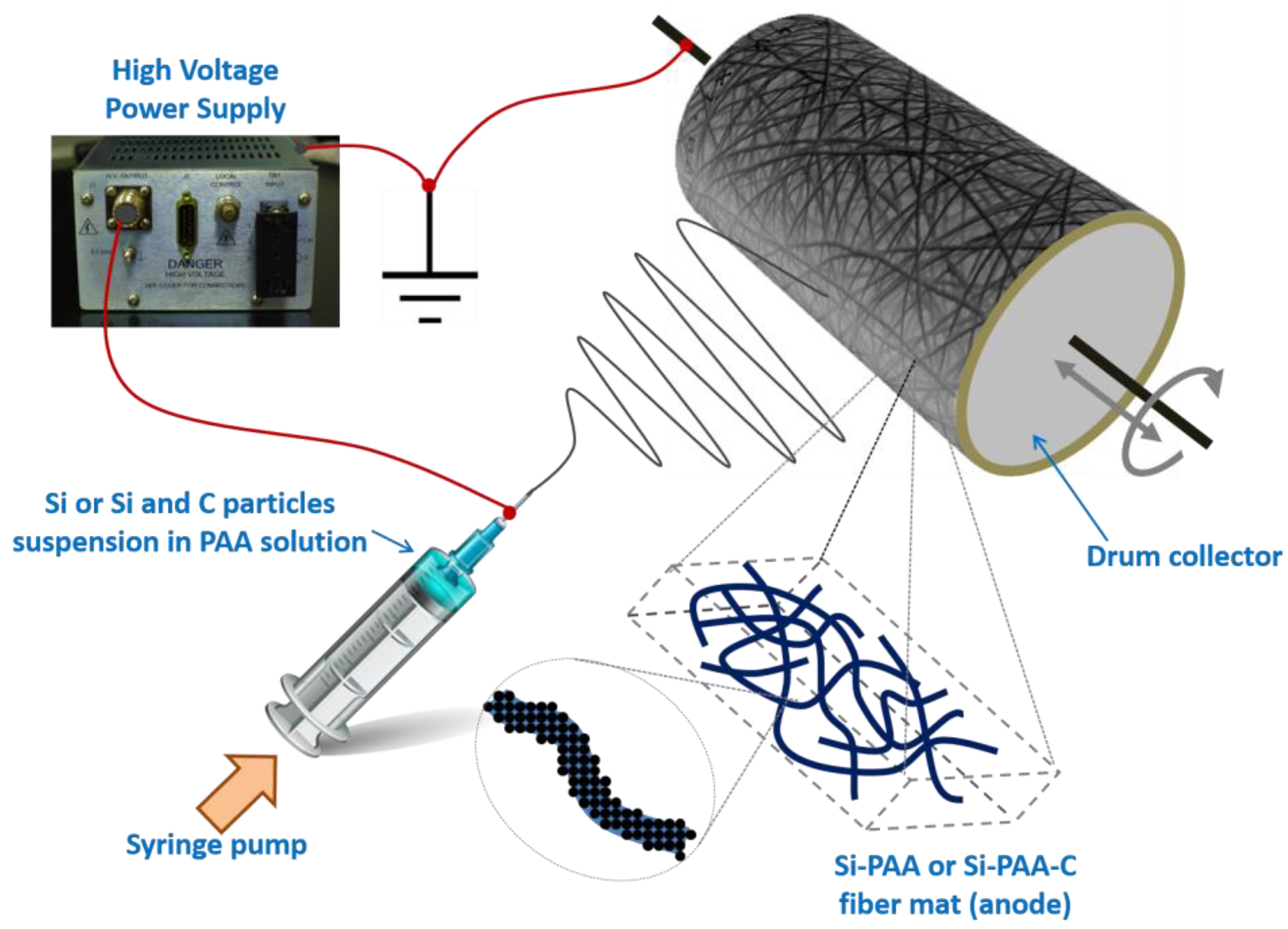
Figure 2.
SEM images of (a) raw electrospun Si/PAA (40 wt.% PAA) fiber mat, and (b) final electrode obtained after fiber welding and mat densification. Magnification 3000×.
Figure 2.
SEM images of (a) raw electrospun Si/PAA (40 wt.% PAA) fiber mat, and (b) final electrode obtained after fiber welding and mat densification. Magnification 3000×.
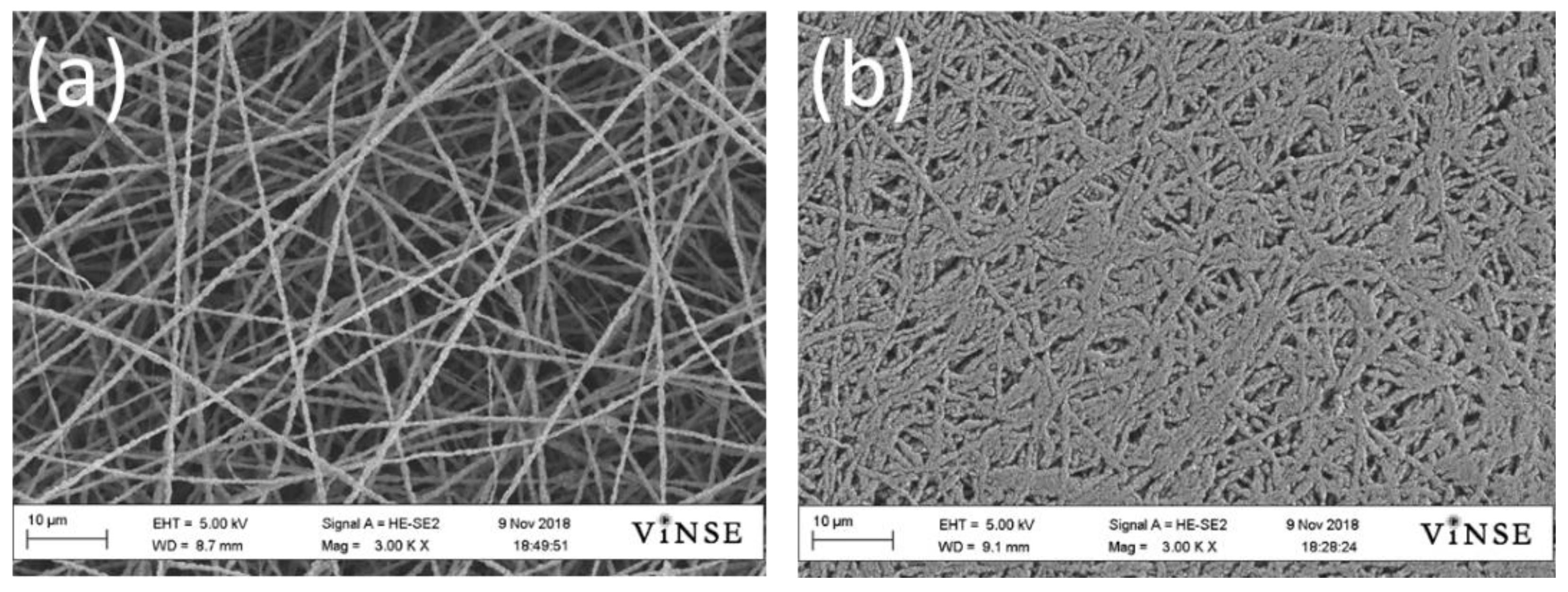
Figure 3.
Cycling results for Li-ion half-cells where the fiber mat or slurry anode contains only Si nanoparticles and PAA binder. (a) Electrospun single fiber Si/PAA anodes with different Si nanoparticle loading and PAA content: (1) 0.29 mgSi/cm2–36 wt.% PAA, (2) 0.35 mgSi/cm2–40 wt.% PAA, (3) 0.95 mgSi/cm2–40 wt.% PAA, (4) 1.00 mgSi/cm2–40 wt.% PAA. (b) Slurry-cast anodes containing 40 wt.% PAA and different Si nanoparticle loadings: (1) 0.43 mgSi/cm2, (2) 0.50 mgSi/cm2, (3) 1.22 mgSi/cm2, (4) 1.57 mgSi/cm2. The first 5 cycles were carried out at 0.1C, followed by 50 cycles at 1C.

Figure 4.
Summary comparison of discharge capacities of fiber mat anode coin cells after 50 cycles at 1C, where the anode mats contained Si and PAA only (no carbon). The box labels next to the data points show areal discharge capacities in mAh/cm2.
Figure 4.
Summary comparison of discharge capacities of fiber mat anode coin cells after 50 cycles at 1C, where the anode mats contained Si and PAA only (no carbon). The box labels next to the data points show areal discharge capacities in mAh/cm2.
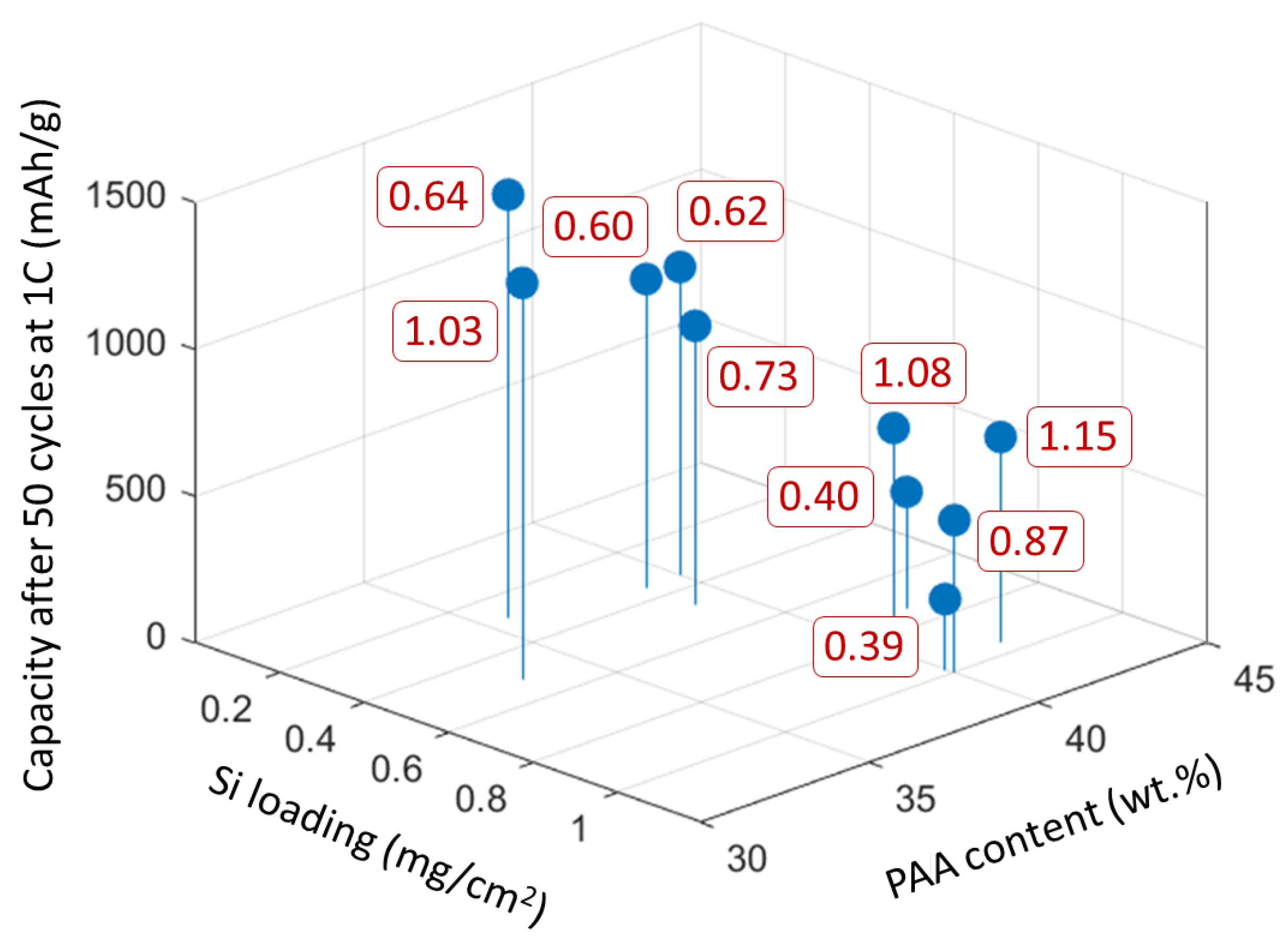
Figure 5.
The effect of Si areal loading on gravimetric capacity for electrospun single fiber Si/PAA anodes (full circles) and slurry-cast Si/PAA anodes (open circles) after 5 cycles at 0.1C (a) and an additional 50 cycles at 1C rate. (b) Electrospun anodes contained 33–42 wt.% PAA and slurry-cast anodes contained 40 wt.% PAA.

Figure 6.
Cycling results (effective gravimetric capacity during discharge) for half-cells with anodes prepared from densified single fiber Si/PAA-C mats and a Li metal counter/reference electrodes: (1) 3 wt.% C–0.97 mgSi/cm2; (2) 6 wt.% C–0.70 mg Si/cm2; (3) 12 wt.% C–0.62 mgSi/cm2; (4) 9 wt.% C–1.17 mgSi/cm2; (5) 12 wt.% C–1.39 mgSi/cm2. Cells were preconditioned for 5 cycles at 0.1C (these data are not shown in the plot) followed by 50 cycles at 1C.
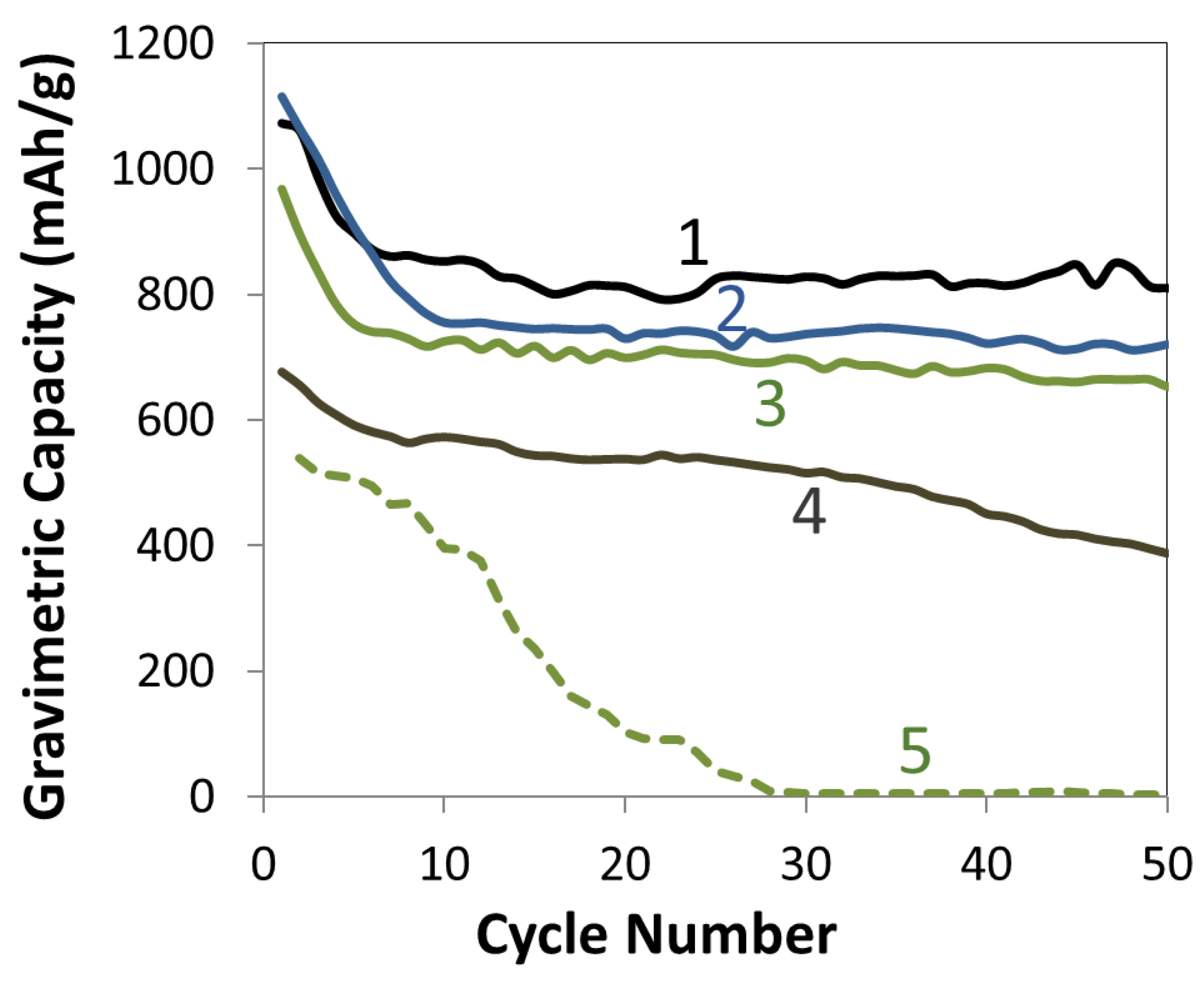
Figure 7.
SEM images of compacted electrospun single fiber Si/PAA-C anodes with (a) lower carbon content (6 wt.%), and with (b) higher carbon content (12 wt.%). Magnification 10,000×.
Figure 7.
SEM images of compacted electrospun single fiber Si/PAA-C anodes with (a) lower carbon content (6 wt.%), and with (b) higher carbon content (12 wt.%). Magnification 10,000×.

Table 1.
Anode fiber mat composition and areal capacity after 50 charge/discharge cycles at 1C for the low-carbon single fiber experiments. Total solids loading refers to the sum of the Si, carbon, and binder contents.
Table 1.
Anode fiber mat composition and areal capacity after 50 charge/discharge cycles at 1C for the low-carbon single fiber experiments. Total solids loading refers to the sum of the Si, carbon, and binder contents.
| C Content (wt.%) | Total Solids Loading (mg/cm2) | Si Loading (mgSi/cm2) | Areal Capacity after 50 Cycles at 1C (mAh/cm2) |
|---|---|---|---|
| 3 | 1.7 | 0.97 | 1.38 |
| 6 | 1.3 | 0.70 | 0.94 |
| 12 | 1.3 | 0.62 | 0.85 |
| 9 | 2.3 | 1.17 | 0.89 |
| 12 | 2.9 | 1.39 | 0.01 |
Disclaimer/Publisher’s Note: The statements, opinions and data contained in all publications are solely those of the individual author(s) and contributor(s) and not of MDPI and/or the editor(s). MDPI and/or the editor(s) disclaim responsibility for any injury to people or property resulting from any ideas, methods, instructions or products referred to in the content. |
© 2023 by the authors. Licensee MDPI, Basel, Switzerland. This article is an open access article distributed under the terms and conditions of the Creative Commons Attribution (CC BY) license (https://creativecommons.org/licenses/by/4.0/).
Share and Cite
MDPI and ACS Style
Mondal, A.N.; Wycisk, R.; Waugh, J.; Pintauro, P.N. Electrospun Si and Si/C Fiber Anodes for Li-Ion Batteries. Batteries 2023, 9, 569. https://doi.org/10.3390/batteries9120569
AMA Style
Mondal AN, Wycisk R, Waugh J, Pintauro PN. Electrospun Si and Si/C Fiber Anodes for Li-Ion Batteries. Batteries. 2023; 9(12):569. https://doi.org/10.3390/batteries9120569
Chicago/Turabian StyleMondal, Abhishek N., Ryszard Wycisk, John Waugh, and Peter N. Pintauro. 2023. "Electrospun Si and Si/C Fiber Anodes for Li-Ion Batteries" Batteries 9, no. 12: 569. https://doi.org/10.3390/batteries9120569
Note that from the first issue of 2016, this journal uses article numbers instead of page numbers. See further details here.