Enhanced Photon-Pair Generation Based on Thin-Film Lithium Niobate Doubly Resonant Photonic Crystal Cavity


Abstract
1. Introduction
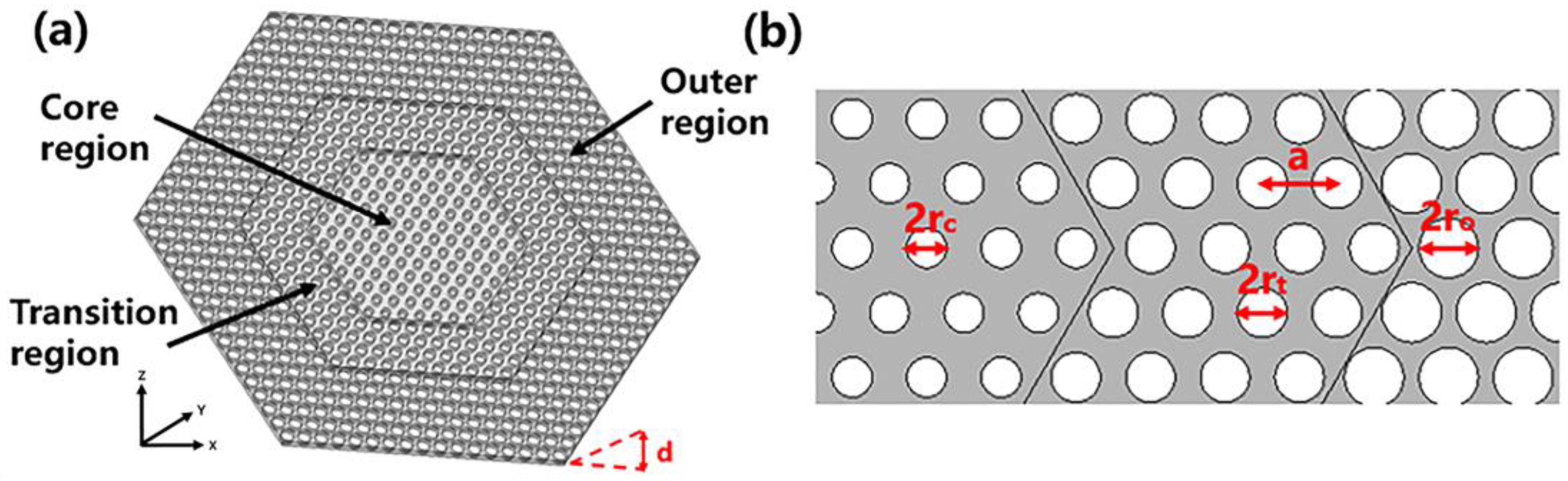
2. Model and Theory
- Calculate the dispersion relationship of photonic structure of the PhC using the finite element method (FEM, COMSOL Multiphysics 6.0).
- Identify a band-edge mode below the light line as the FH mode for frequency ω1, and a band-edge mode beyond the light cone at frequency ω2 as the SH mode.
- Verify that the FH and SH modes have a nonzero nonlinear overlap factor, depending on the χ2 tensor of the defined material.
- Vary the hole radius and the slab thickness to match the doubly resonant condition ω2 ≈ 2ω1.
- Synthesize the FH and SH modes by appropriately configurating the PhC cavity.
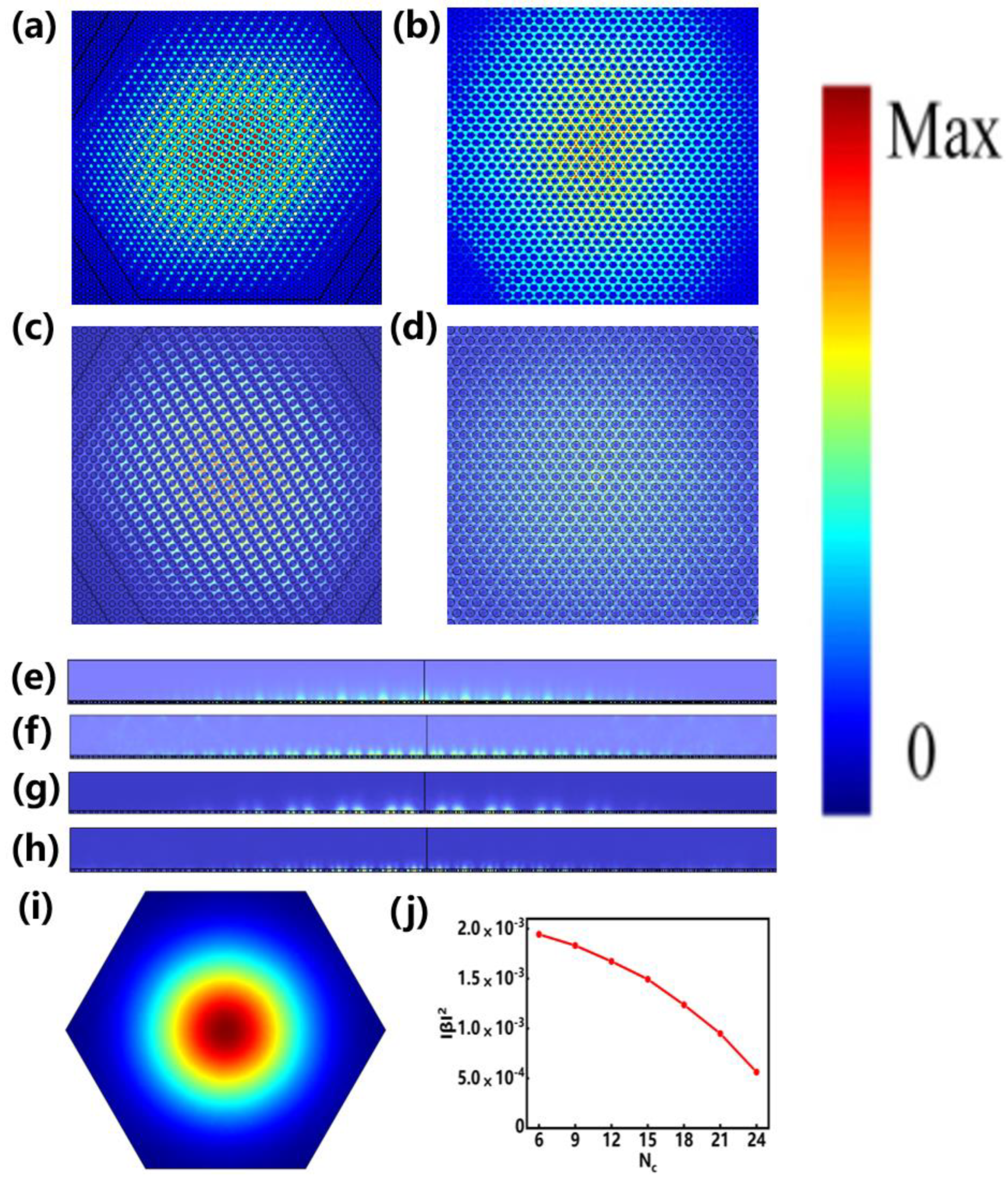
3. Results and Discussion
4. Conclusions
Author Contributions
Funding
Institutional Review Board Statement
Informed Consent Statement
Data Availability Statement
Conflicts of Interest
References
- Gisin, N.; Ribordy, G. Quantum cryptography. Rev. Mod. Phys. 2002, 74, 145–195. [Google Scholar] [CrossRef]
- Bouwmeester, D.; Pan, J.W.; Mattle, K.; Eibl, M.; Weinfurter, H.; Zeilinger, A. Experimental quantum teleportation. Nature 1997, 390, 575–579. [Google Scholar] [CrossRef]
- Chang, D.E.; Vuletić, V.; Lukin, M.D. Quantum nonlinear optics—Photon by photon. Nat. Photonics 2014, 8, 685–694. [Google Scholar] [CrossRef]
- Wang, Y.; Jöns, K.D.; Sun, Z. Integrated photon-pair sources with nonlinear optics. Appl. Phys. Rev. 2021, 8, 011314. [Google Scholar] [CrossRef]
- Kwiat, P.G.; Mattle, K.; Weinfurter, H.; Zeilinger, A.; Sergienko, A.V.; Shih, Y. New high-intensity source of polarization-entangled photon pairs. Phys. Rev. Lett. 1995, 75, 4337. [Google Scholar] [CrossRef]
- Sharping, J.E.; Lee, K.F.; Foster, M.A.; Turner, A.C.; Schmidt, B.S.; Lipson, M.; Gaeta, A.L.; Kumar, P. Generation of correlated photons in nanoscale silicon waveguides. Opt. Express 2006, 14, 12388–12393. [Google Scholar] [CrossRef] [PubMed]
- Collins, M.J.; Xiong, C.; Rey, I.H.; Vo, T.D.; He, J.; Shahnia, S.; Reardon, C.; Krauss, T.F.; Steel, M.J.; Clark, A.S.; et al. Integrated spatial multiplexing of heralded single-photon sources. Nat. Commun. 2013, 4, 2582. [Google Scholar] [CrossRef] [PubMed]
- Tanzilli, S.; Martin, A.; Kaiser, F.; De Micheli, M.P.; Alibart, O.; Ostrowsky, D.B. On the genesis and evolution of Integrated Quantum Optics. Laser Photonics Rev. 2012, 6, 115–143. [Google Scholar] [CrossRef]
- Silverstone, J.W.; Bonneau, D.; O’Brien, J.L.; Thompson, M.G. Silicon quantum photonics. IEEE J. Sel. Top. Quantum Electron. 2016, 22, 390–402. [Google Scholar] [CrossRef]
- Schreiber, A.; Cassemiro, K.N.; Potoček, V.; Gábris, A.; Mosley, P.J.; Andersson, E.; Jex, I.; Silberhorn, C. Photons Walking the Line: A Quantum Walk with Adjustable Coin Operations. Phys. Rev. Lett. 2010, 104, 050502. [Google Scholar] [CrossRef]
- Giovannetti, V.; Lloyd, S.; Maccone, L. Quantum-enhanced measurements: Beating the standard quantum limit. Science 2004, 306, 1330–1336. [Google Scholar] [CrossRef] [PubMed]
- Zhang, W.; Fickler, R.; Giese, E.; Chen, L.; Boyd, R.W. Influence of pump coherence on the generation of position-momentum entanglement in optical parametric down-conversion. Opt. Express 2019, 27, 20745–20753. [Google Scholar] [CrossRef]
- Berger, V. Second-harmonic generation in monolithic cavities. J. Opt. Soc. Am. B 1997, 14, 1351–1360. [Google Scholar] [CrossRef]
- Scaccabarozzi, L.; Fejer, M.M.; Huo, Y.; Fan, S.; Yu, X.; Harris, J.S. Enhanced second-harmonic generation in AlGaAs/AlxOy tightly confining waveguides and resonant cavities. Opt. Lett. 2006, 31, 3626–3628. [Google Scholar] [CrossRef]
- Wang, J.; Clementi, M.; Minkov, M.; Barone, A.; Carlin, J.F.; Grandjean, N.; Gerace, D.; Fan, S.; Galli, M.; Houdré, R. Doubly resonant second-harmonic generation of a vortex beam from a bound state in the continuum. Optica 2020, 7, 1126–1132. [Google Scholar] [CrossRef]
- Ge, R.; Liu, X.; Yan, X.; Chen, X.; Chen, Y. Doubly resonant photonic crystal cavity using merged bound states in the continuum. Phys. Rev. B 2023, 107, 165406. [Google Scholar] [CrossRef]
- Liscidini, M.; Andreani, L.C. Second-harmonic generation in doubly resonant microcavities with periodic dielectric mirrors. Phys. Rev. E 2006, 73, 016613. [Google Scholar] [CrossRef]
- Lin, Z.; Liang, X.; Lončar, M.; Johnson, S.G.; Rodriguez, A.W. Cavity-enhanced second-harmonic generation via nonlinear-overlap optimization. Optica 2016, 3, 233–238. [Google Scholar] [CrossRef]
- Tu, Z.; Zhang, J.; Alonso-Ramos, C.; Roux, X.L.; Vivien, L.; Cassan, E. Doubly resonant distributed feedback cavity with controllable wide wavelength separation. Opt. Commun. 2021, 494, 127064. [Google Scholar] [CrossRef]
- Medina-Vázquez, J.A.; González-Ramírez, E.Y.; Murillo-Ramírez, J.G. Photonic crystal meso-cavity with double resonance for second-harmonic generation. J. Phys. B At. Mol. Opt. Phys. 2022, 54, 245401. [Google Scholar] [CrossRef]
- Hong, P.; Xu, L.; Rahmani, M. Dual bound states in the continuum enhanced second harmonic generation with transition metal dichalcogenides monolayer. Opto-Electron. Adv. 2022, 5, 200097-1–200097-8. [Google Scholar] [CrossRef]
- Simonneau, C.; Debray, J.P.; Harmand, J.C.; Vidaković, P.; Lovering, D.J.; Levenson, J.A. Second-harmonic generation in a doubly resonant semiconductor microcavity. Opt. Lett. 1997, 22, 1775–1777. [Google Scholar] [CrossRef] [PubMed]
- Rivoire, K.; Buckley, S.; Vučković, J. Multiply resonant photonic crystal nanocavities for nonlinear frequency conversion. Opt. Express 2011, 19, 22198–22207. [Google Scholar] [CrossRef] [PubMed]
- Pernice, W.H.P.; Xiong, C.; Schuck, C.; Tang, H.X. Second harmonic generation in phase matched aluminum nitride waveguides and micro-ring resonators. Appl. Phys. Lett. 2012, 100, 223501. [Google Scholar] [CrossRef]
- Bruch, A.W.; Liu, X.; Guo, X.; Surya, J.B.; Gong, Z.; Zhang, L.; Wang, J.; Yan, J.; Tang, H.X. 17000%/W second-harmonic conversion efficiency in single-crystalline aluminum nitride microresonators. Appl. Phys. Lett. 2018, 113, 131102. [Google Scholar] [CrossRef]
- Celebrano, M.; Wu, X.; Baselli, M.; Großmann, S.; Biagioni, P.; Locatelli, A.; De Angelis, C.; Cerullo, G.; Osellame, R.; Hecht, B.; et al. Mode matching in multiresonant plasmonic nanoantennas for enhanced second harmonic generation. Nat. Nanotechnol. 2015, 10, 412–417. [Google Scholar] [CrossRef]
- Ai, Q.; Sterl, F.; Zhang, H.; Wang, J.; Giessen, H. Giant Second Harmonic Generation Enhancement in a High-Q Doubly Resonant Hybrid Plasmon–Fiber Cavity System. ACS Nano 2021, 15, 19409–19417. [Google Scholar] [CrossRef]
- Minkov, M.; Gerace, D.; Fan, S. Doubly resonant χ(2) nonlinear photonic crystal cavity based on a bound state in the continuum. Optica 2019, 6, 1039–1045. [Google Scholar] [CrossRef]
- Mohamed, M.S.; Simbula, A.; Carlin, J.F.; Minkov, M.; Gerace, D.; Savona, V.; Grandjean, N.; Galli, M.; Houdré, R. Efficient continuous-wave nonlinear frequency conversion in high-Q gallium nitride photonic crystal cavities on silicon. APL Photonics 2017, 2, 031301. [Google Scholar] [CrossRef]
- Ge, X.; Minkov, M.; Fan, S.; Li, X.; Zhou, W. Low index contrast heterostructure photonic crystal cavities with high quality factors and vertical radiation coupling. Appl. Phys. Lett. 2018, 112, 141105. [Google Scholar] [CrossRef]
- Zanotti, S.; Minkov, M.; Fan, S.; Andreani, L.C.; Gerace, D. Doubly-resonant photonic crystal cavities for efficient second-harmonic generation in III–V semiconductors. Nanomaterials 2021, 11, 605. [Google Scholar] [CrossRef] [PubMed]
- Poddubny, A.N.; Iorsh, I.V.; Sukhorukov, A.A. Generation of Photon-Plasmon Quantum States in Nonlinear Hyperbolic Metamaterials. Phys. Rev. Lett. 2016, 117, 123901. [Google Scholar] [CrossRef] [PubMed]
- Lenzini, F.; Poddubny, A.N.; Titchener, J.; Fisher, P.; Boes, A.; Kasture, S.; Haylock, B.; Villa, M.; Mitchell, A.; Solntsev, A.S.; et al. Direct characterization of a nonlinear photonic circuit’s wave function with laser light. Light Sci. Appl. 2018, 7, 17143. [Google Scholar] [CrossRef] [PubMed]
- Duong, N.M.H.; Saerens, G.; Timpu, F.; Buscaglia, M.T.; Buscaglia, V.; Morandi, A.; Muller, J.S.; Maeder, A.; Kaufmann, F.; Solntsev, A.S.; et al. Broadband photon pair generation from a single lithium niobate microcube. arXiv 2021, arXiv:2109.08489. [Google Scholar]
- Muller, J.S.; Morandi, A.; Grange, R.; Savo, R. Modeling of random quasi-phase-matching in birefringent disordered media. Phys. Rev. Appl. 2021, 15, 064070. [Google Scholar] [CrossRef]
- Altepeter, J.B.; Jeffrey, E.R.; Kwiat, P.G. Phase-compensated ultra-bright source of entangled photons. Opt. Express 2005, 13, 8951–8959. [Google Scholar] [CrossRef]
- Niu, X.; Huang, Y.; Xiang, G.; Guo, G.; Ou, Z. Beamlike high-brightness source of polarization-entangled photon pairs. Opt. Lett. 2008, 33, 968–970. [Google Scholar] [CrossRef]


| Reference | Material | QFH | QSH | |β|2 | SHG Efficiency(/W) |
|---|---|---|---|---|---|
| [15] | GaN | 2000 | 800 | / | 2.4 × 10⁻² |
| [18] | AlGaAs | 5000 | 1000 | 1.6 × 10⁻⁶ | 16 |
| [16] | LN | 160,000 | 2000 | 6 × 10⁻⁴ | 48 |
| [31] | GaN | 36,000 | 1100 | 1 × 10⁻⁴ | 2.9 |
| [31] | AlGaAs | 110,000 | 400 | 1.2 × 10⁻⁵ | 112 |
| This work | LN | 280,000 | 2100 | 5.6 × 10⁻⁴ | 133 |
Disclaimer/Publisher’s Note: The statements, opinions and data contained in all publications are solely those of the individual author(s) and contributor(s) and not of MDPI and/or the editor(s). MDPI and/or the editor(s) disclaim responsibility for any injury to people or property resulting from any ideas, methods, instructions or products referred to in the content. |
© 2024 by the authors. Licensee MDPI, Basel, Switzerland. This article is an open access article distributed under the terms and conditions of the Creative Commons Attribution (CC BY) license (https://creativecommons.org/licenses/by/4.0/).
Share and Cite
Zhu, J.; Liu, F.; Fu, F.; Wei, Y.; Yang, T.; Guan, H.; Lu, H. Enhanced Photon-Pair Generation Based on Thin-Film Lithium Niobate Doubly Resonant Photonic Crystal Cavity. Photonics 2024, 11, 470. https://doi.org/10.3390/photonics11050470
Zhu J, Liu F, Fu F, Wei Y, Yang T, Guan H, Lu H. Enhanced Photon-Pair Generation Based on Thin-Film Lithium Niobate Doubly Resonant Photonic Crystal Cavity. Photonics. 2024; 11(5):470. https://doi.org/10.3390/photonics11050470
Chicago/Turabian StyleZhu, Jinmian, Fengli Liu, Fangheng Fu, Yuming Wei, Tiefeng Yang, Heyuan Guan, and Huihui Lu. 2024. "Enhanced Photon-Pair Generation Based on Thin-Film Lithium Niobate Doubly Resonant Photonic Crystal Cavity" Photonics 11, no. 5: 470. https://doi.org/10.3390/photonics11050470
APA StyleZhu, J., Liu, F., Fu, F., Wei, Y., Yang, T., Guan, H., & Lu, H. (2024). Enhanced Photon-Pair Generation Based on Thin-Film Lithium Niobate Doubly Resonant Photonic Crystal Cavity. Photonics, 11(5), 470. https://doi.org/10.3390/photonics11050470