Abstract
Structured light three-dimensional reconstruction is one of the important methods for non-contact acquisition of sparse texture object surfaces. Variations in ambient illumination and disparities in object surface reflectance can significantly impact the fidelity of three-dimensional reconstruction, introducing considerable inaccuracies. We introduce a robust method for color speckle structured light encoding, which is based on a variant of the De Bruijn sequence, termed the Homogeneous De Bruijn Sequence. This innovative approach enhances the reliability and accuracy of structured light techniques for three-dimensional reconstruction by utilizing the distinctive characteristics of Homogeneous De Bruijn Sequences. Through a pruning process applied to the De Bruijn sequence, a structured light pattern with seven distinct color patches is generated. This approach ensures a more equitable distribution of speckle information.
1. Introduction
Three-dimensional reconstruction technology is an important branch of computer vision technology and a popular research field that combines computer vision and industrial measurement. However, there are still many challenges and limitations in the current field of 3D reconstruction [].
The technology for reconstructing the surface of objects through visual measurement is divided into active 3D reconstruction and passive 3D reconstruction, depending on whether an active light source is required. Passive measurement does not require the emission of a light source, thus it can accurately capture the behavior and state of the target object in outdoor environments with natural lighting conditions. The advantages of passive measurement, such as its lower cost and complexity, make it more readily applicable to a variety of fields and scenarios []. With the advancement of machine learning technology, stereo vision based on machine learning has become an important branch in the field of passive 3D reconstruction. Currently, mainstream methods include ACVNet, GANet, etc. GANet uses semi-global aggregation layers and local guided aggregation layers to replace traditional CNN networks for more accurate depth estimation []. ACVNet, on the other hand, proposes a new cost-volume construction method []. These methods have improved the quality of stereo matching to varying degrees. However, in scenarios involving the reconstruction of surfaces with sparse textures, the reconstruction effect tends to be poor due to the absence or repetition of textures.
Active three-dimensional scanners based on structured light project one or more two-dimensional structured patterns onto the surface of objects in the scene and obtain three-dimensional shapes by analyzing the information in the captured object images [,,]. These specially designed patterns can be projected using a projector or other suitable light sources.
Depending on the pattern design strategy, structured light-encoding techniques can be divided into temporal encoding and spatial encoding. For temporal structured light-encoding methods, a series of pattern images are required, and the target surface is encoded at different phases along the time axis. In [], the main commonly used methods of temporal and spatial encoding are summarized. Phase-shifting methods are a commonly used temporal-encoding projection method that projects a set of sinusoidal patterns with phase shifts to the object surface for three-dimensional reconstruction. Lally et al. proposed a three-dimensional shape measurement algorithm based on multiple references, with a root mean square surface error of less than 0.03 mm []. Ref. [] developed a 556 Hz system that uses a tri-frequency algorithm to measure multiple objects simultaneously. While these temporal-encoding methods have demonstrated impressive results in terms of accuracy and precision, it is important to note that they often require specialized equipment and hardware. As a result, the cost of implementing time-encoding structured light systems can be relatively high.
Spatial-coding structured light can be classified based on whether it projects grayscale or colored patterns. Grayscale structured light typically utilizes grayscale values for encoding, which is susceptible to interference from ambient lighting. Variations in lighting conditions can lead to changes in the captured grayscale information. Compared to grayscale structured light, colored structured light contains more information and has a stronger resistance to ambient light []. The common method for color-structured light encoding is De Bruijn encoding []. To ensure the uniqueness of the encoding pattern sequence, De Bruijn sequences are often used for encoding. In [], a grid projection mode composed of horizontal and vertical stripes encoded with De Bruijn sequences is used, which can be decoded quickly and accurately with simple geometric constraints. However, these constraints are difficult to satisfy in complex scenes, leading to decoding errors. Refs. [,] use an RGB color space for stripe encoding based on De Bruijn sequences, but due to the poor independence and strong crosstalk of RGB color channels, the precision of stripe segmentation is reduced. Ref. [] employs Hamming codes for color stripe encoding and uses dynamic programming and GPU acceleration techniques to significantly increase decoding speed, but the color separation is not accurate enough, resulting in a decrease in precision. Color classification of the colored stripes is both a challenge and a focus during the decoding process. Refs. [,] use the K-means algorithm for color classification of colored encoding stripes, fitting straight lines for each projected color in the color space and selecting the color space origin (0,0,0) as the common point for all lines. However, experimental results show that not all point clusters can satisfy this condition, leading to errors in color classification. Ref. [] proposes a color classification method based on cluster analysis, which can reduce color crosstalk but is only suitable for modulated projection images where the pixel points of each color class are linearly distributed.
The structured light encoded by De Bruijn sequences also has some issues []. Due to the fact that the subsequences of De Bruijn sequences are not necessarily balanced in each window, and a code element may be redundantly projected, leading to images with repeated and unbalanced code elements, the reconstruction effect is poor. The three-dimensional reconstruction algorithm based on a Homogeneous De Bruijn sequence proposed in this paper has the following improvements:
- It can reconstruct dense surface information from a single capture;
- In the field of structured light encoding, there are challenges related to unclear texture feature encoding in sub-window De Bruijn sequences and decoding difficulties. To overcome these issues, a homogeneous constraint for sub-window encoding has been introduced, it ensures that in each encoding window, all color channels appear at least once as 0 and 1. This approach enables the generation of structured light patterns with high contrast and improved ease of decoding;
- In the field of structured light decoding, a common problem is crosstalk caused by the reflection and scattering of colors from adjacent pixels in color images. To tackle this issue, advancements have been made in the decoding algorithm by introducing normalization and the c1c2c3 sequence to enhance color features. Additionally, the utilization of the Fuzzy C-Means (FCM) clustering algorithm is proposed for extracting color information. This approach can greatly improve the accuracy of the reconstructed point cloud.
This paper is structured as follows. Section 2 introduces the specific principles of De Bruijn encoding. Section 3 presents the encoding and decoding schemes of the three-dimensional reconstruction method based on Homogeneous De Bruijn sequences. Section 4 demonstrates the reconstruction accuracy and density of different speckle encoding patterns as well as decoding schemes. Finally, the conclusion is drawn in Section 5.
2. De Bruijn Sequence Encoding
To ensure the accuracy of the point cloud in three-dimensional reconstruction, the color speckle must meet several requirements: (i) local uniqueness, (ii) ease of extracting encoding information, and (iii) high contrast. The size of the entire speckle pattern projection should match the resolution of the projector. To achieve high image contrast, the channel grayscale values of the speckle image should be determined by binary encoding.
Since the spectral responses of the R, G, and B channels of color cameras are typically different, to make the captured color images have as similar contrast in the R, G, and B channels as possible, we can adjust the gain of each channel of the color camera and the intensity of the RGB image channels of the projection, as shown in Equation (1).
where represents the projected image and , , and denote its three binary channels, with , , and corresponding to their respective intensities. Depending on the ambient light and the properties of the reconstructed object, it is advisable to set different values for , , and []. In this paper, they are set to 255, 210, and 210.
The De Bruijn encoding technique is incorporated into the generation of the speckle pattern, where the pixel of the speckle, that is, the combination of the channel grayscale values for each speckle block, is determined by the locally unique sequences generated by De Bruijn. Since De Bruijn generates a one-dimensional sequence, the color speckle structured light is expanded from two dimensions into a one-dimensional template, with different colors representing De Bruijn sequence elements within this template. The color speckle structured light template is composed of the following two steps:
- creating a random speckle template for encoding the speckle block information.
- embedding color information into the random speckle template.
In traditional De Bruijn encoding, self-loops are allowed at each encoding code, meaning that a code element can be the next node in the encoding path for itself. This leads to multiple consecutive speckle blocks being encoded as the same color code element, resulting in some windows where the binary encoding distribution of the RGB channels within the speckle is uneven. This increases the error in color feature extraction based on corner points. This paper designs a pruning method that can remove these paths during the speckle design process. The code elements used in De Bruijn encoding are shown in Table 1.

Table 1.
Structured Light Code Elements.
The Homogeneous De Bruijn Sequence proposed in this study, which eliminates self-loops, is generated with given values of k and n, resulting in k order elements and a window size of n, where each subsequence of length n appears exactly once in a cycle. For the RGB color space, the symbols of the De Bruijn alphabet represent all combinations of the 01 channels, which can be expressed as 3-bit binary numbers; these are black (000, K), red (100, R), green (010, G), blue (001, B), yellow (110, Y), magenta (101, M), cyan (011, C), and white (111, W). White is discarded due to the propensity for overexposure, and black is also discarded to reserve a code element as a spare. Consequently, the alphabet for constructing the De Bruijn sequence consists of k = 6 order elements, forming the code element set S = {R, G, B, Y, M, C}.
The De Bruijn sequence without self-loops is constructed as an Eulerian circuit on a pruned De Bruijn graph, where edges corresponding to windows that do not satisfy the aforementioned conditions are removed. The vertex set of the De Bruijn graph is defined as:
The set of edges of the graph, defined as R, corresponds to the encoding paths generated by the De Bruijn sequence:
As shown in Figure 1, we consider a partial set of vertices from the De Bruijn-directed graph, such as GBR, BRK, and MYB. These vertices represent three encoded subsequences of sub-windows. Among them, GBR to BRK satisfies the requirement of Equation (3), indicating that there exists an edge connecting GBR to BRK. However, GBR to MYB does not meet the requirement, hence there is no edge between these two vertices.
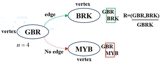
Figure 1.
Partial construction sequence of the De Bruijn-directed graph. In the green box, the overlapping elements of the two vertices are consistent, which can serve as a path in the De Bruijn directed graph. In the red box, the overlapping elements of the two vertices are inconsistent, and thus cannot serve as a path in the De Bruijn directed graph.
The three-dimensional reconstruction algorithm based on the Homogeneous De Bruijn sequence is a method that trims the traditional De Bruijn sequence to obtain block coding and decoding. After applying specific structured light coding, it projects onto the target object using a projector. A stereo camera captures the post-projection image, decodes the color features, and performs preprocessing such as normalization on the captured image. Subsequently, FCM clustering is employed to extract color features, which are then used to reconstruct a three-dimensional point cloud of the object’s surface. The algorithm process is shown in Figure 2.
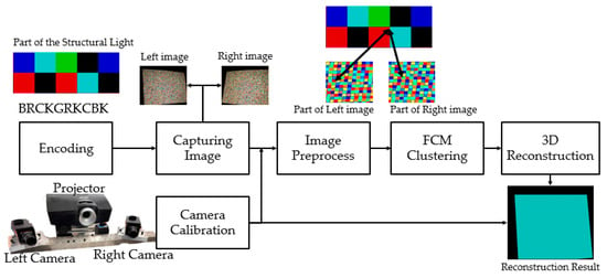
Figure 2.
Flow diagram of the three-dimensional reconstruction algorithm based on a Homogeneous De Bruijn sequence.
3. Key Technology and Algorithm
3.1. Homogeneous De Bruijn Sequence Generation
From the aforementioned De Bruijn graph, a k-order, n-window size De Bruijn sequence B(k, n) can be generated. However, traditional De Bruijn sequence encoding has some issues:
- De Bruijn sequence encoding does not consider the balance of sub-window sequences, which means it cannot guarantee that all color channels in a De Bruijn window will cover the entire available dynamic range.
- Some sub-windows in De Bruijn sequence encoding do not take into account the contrast between color codewords, resulting in low decoding efficiency and a high rate of misidentification.
To address these issues, we propose the Homogeneous De Bruijn Sequence, which involves pruning the generation path of traditional De Bruijn edges. The pruned De Bruijn sequence, referred to as P(k, n), can be described by the sequence of extracted Eulerian paths. This ensures that the sub-window encoding of the final generated sequence satisfies the homogeneous requirement. The specific requirements for homogeneous sub-window encoding are as follows:
- The values of the codewords for any two consecutive elements must be distinct;
- The j-th channel binary bit should have at least one symbol with a value of 0 in each De Bruijn window;
- The j-th channel binary bit should have at least one symbol with a value of 1 in each De Bruijn window; where j = {1, 2, 3}.
The algorithm for generating a pruned De Bruijn sequence P(k, n) of length L that satisfies the aforementioned conditions should traverse all possible paths, evaluate whether they meet the requirements for a non-self-loops sequence, and mark the visited paths for pruning or retention.
Figure 3 illustrates a method for extracting sequences from a pruned De Bruijn graph. For the sake of demonstration, the code elements are taken from a subset S1 = {R, G, M}. In the case of k = 3 and n = 3, The initial sequence of length k−1 is randomly selected as GG, and one edge is chosen from all reachable edges. When the path GG to GR is selected as the next path, indicating that the next element is R, it causes all grayscale binary codes in the blue channel to be 0, resulting in a non-homogeneous situation in this window. In such cases, the algorithm prunes this particular edge and selects a new edge for GG. Consequently, while the total length of the generated sequence may be shorter than that of a non-homogeneous De Bruijn sequence, its information density becomes more enriched. For instance, a partial sequence of P(3,3) generated is GGMGRMGMRGMMGG.
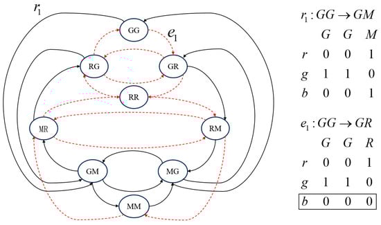
Figure 3.
Directed Graph of the P(3,3) Sequence Generated Based on S1 = {R, G, M}. Solid arrows indicate paths that satisfy homogeneous constraints. Red dashed arrows show paths that violate these constraints and should be pruned.
Compared to the approach of inserting black stripes between every two colored stripes in stripe-structured light [], to obtain dense point cloud information, the speckle blocks need to be closely arranged. However, if adjacent speckle blocks have the same color, it can interfere with color extraction. To avoid the occurrence of consecutive identical speckle blocks within a window, after generating the speckles, we traverse the entire speckle map with a 2 × 2 window. If consecutive identical speckle blocks are detected, we replace the original speckle blocks with black speckle blocks that are not listed in Table 1.
3.2. Feature Point Detecting
Traditional speckle information only carries grayscale information, reflecting changes in illumination intensity. In this paper, matching is divided into sparse and dense matching. Color binary strings are encoded in the projected speckles, and sparse matching involves decoding the encoding of the projected speckles to obtain color feature values, which are then matched with images captured by a stereo system.
In the matching algorithm, the grayscale values of each pixel are first quantized to scale the grayscale values to the same range, eliminating the dimensional differences between features, as shown in Equation (4).
where represents the grayscale coefficient. When the grayscale values of the three channels fall within a certain range of the maximum value, the pixel is considered to be a black speckle block or an image noise point and is not processed; denotes the mapping interval range. When is set to 255, the color space is mapped to the range of 0 to 255, which is typically used in situations where the illumination intensity is relatively uniform.
Due to factors such as color texture, non-uniform reflection, specular reflection, and mutual reflection, there are significant differences between the RGB color values in the projected pattern and those obtained in the captured image. Therefore, the recognition of structured light colors is highly challenging, and conventional color classification methods often struggle to achieve good performance. For identifying the colors in the captured images, the c1c2c3 color feature was selected. The c1c2c3 color feature is derived from the RGB color and is defined as in Equation (5).
The c1c2c3 color feature exhibits a unique characteristic that depends on the spectral sensitivity of the red, green, and blue sensors as well as the surface reflectance. It is independent of factors such as the direction of the light source, the surface normal, or the spectral power distribution of the incident light.
Cluster analysis, specifically the Fuzzy C-Means (FCM) algorithm [], proves to be an excellent method for color classification in this context. Cluster analysis divides an unknown sample set into multiple categories based on high internal similarity and low inter-class similarity. The FCM algorithm is particularly suitable for color classification due to its simplicity and fast computation capabilities [,]. The objective function for clustering is:
where is the weighting exponent, (for ) are the cluster centers for the -th cluster, is the fuzzy membership matrix, represents the degree of membership of sample to the -th cluster, and represents the Euclidean distance between sample and the cluster center .
The iterative update formula for the membership matrix :
The iterative update formula for the cluster centers :
Then, proceed with the clustering iteration according to the following steps:
- Read the captured image and convert it to the c1c2c3 sequence according to Equation (5).
- Compute membership matrix uij using Equation (7).
- Update cluster centers vi based on the weighted averages of samples concerning uij.
- Check for convergence based on cluster center stability and membership matrix changes, repeat Steps 2–4 until convergence is achieved.
As shown in Figure 4. On the actual captured images, due to changes in ambient lighting, the grayscale values of the speckles projected on industrial parts can vary. However, due to the special design of the speckle, by normalizing the processing, the color code closest to the speckle can be extracted, which improves the stability and accuracy of speckle extraction under different lighting conditions. As shown in Figure 4c, after normalization, the clustering is less affected by lighting conditions compared to the unnormalized Figure 4b.
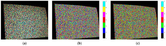
Figure 4.
The decoding results of the captured images. (a) Original image. (b) Clustering result obtained using the k-means method []. (c) Clustering result of our proposed method.
As shown in Table 2, the captured structured light patterns are subjected to uniform processing. The quality of speckle decoding is assessed using the Mean Square Error (MSE) and the Peak Signal-to-Noise Ratio (PSNR) between the projected and captured images and the designed patterns []. The MSE reflects the degree of distortion in an image, and a smaller value is preferred. The PSNR reflects the ratio between the signal strength and the noise intensity in an image, and a larger value is desired. The decoding algorithm proposed in this paper utilizes c1c2c3 encoding, which possesses color invariance. Even under poor lighting conditions where the grayscale values of the captured image are low, c1c2c3 encoding can still maintain consistent recognition of the target color.
Table 2.
Quality of Different Decoding Methods.
4. Experience
To verify the accuracy and effectiveness of the structured light encoding and decoding method proposed in this paper, an experimental setup was constructed for validation The experimental equipment used in this study mainly consists of a structured light projector and two industrial cameras. In the experiment, the distance between the two cameras is 200 mm, and the distance to the object is 500 mm. To validate the precision of the method proposed in this paper, a metallic spherical crown with a radius of 190 mm was used as the reconstruction object.
Figure 5 displays the original image of the spherical crown used in the experiment, as well as the images captured after projecting structured light.
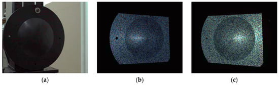
Figure 5.
The images captured by the stereo camera. (a) Reconstruction target object. (b) Image captured by the left camera after projecting the speckle pattern. (c) Image captured by the right camera after projecting the speckle pattern.
We projected the spherical crown with speckles encoded in different ways, and Figure 6 demonstrates the reconstruction effects under different speckle projections.
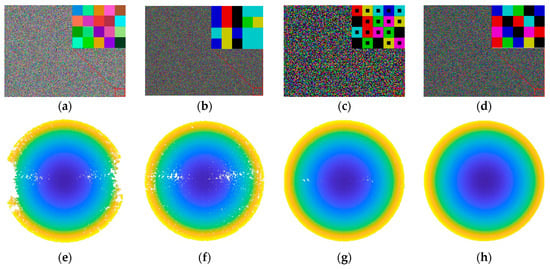
Figure 6.
Experimental results of different speckles. (a) Speckle generated by random three-channel grayscale values. (b) Speckles generated by De Bruijn but containing repetitive subsequences. (c) Speckles generated by integrating black pixel blocks into the center of each binarized grayscale channel. (d) Speckle generated by Homogeneous De Bruijn Sequence. (e–h) represent the spherical crown point clouds reconstructed from the speckle projections of (a–d), respectively.
As Figure 6 shows, the Homogeneous De Bruijn Sequence proposed in this paper effectively improves the issue of voids and avoids the situation of mismatches. The experiments indicate that when the speckle color channel is random grayscale, as shown in Figure 6a, it is not possible to extract color features, resulting in poorer reconstruction effects in areas with low lighting conditions. When the speckle pattern is encoded with De Bruijn but does not satisfy the homogeneous requirement, some holes may still appear, as shown in Figure 6b. By altering the structural information of the speckle blocks and adding black blocks in the middle, the condition of the hole can be improved to some extent, as shown in Figure 6c. However, when using the homogeneous encoding speckle proposed in this paper, the presence of holes is reduced to the maximum extent possible, as shown in Figure 6d.
After obtaining the point cloud data, we also analyzed the error distribution by fitting the world coordinates of the spherical crown’s center and analyzing the errors in the generated point cloud, as shown in Figure 7.
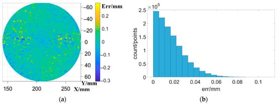
Figure 7.
The error distribution of the experimental method. (a) positional distribution of errors. (b) quantitative distribution of errors.
To verify the robustness of the proposed method under different lighting intensities, images were captured using various exposure times, and the spherical cap was fitted. The distance of each point from the fitted surface was obtained using Equation (9), and the root mean square (RMS) error, Peak-to-Valley (PV) error, and mean error of the reconstructed point cloud were calculated using Equations (10)–(12), respectively. These were then compared with the structured light generated randomly and that generated by De Bruijn, as shown in Table 3. After using the Homogeneous De Bruijn encoding structured light proposed in this paper, there has been a significant improvement in PV error, RMS error, and mean error, satisfying the precision requirements of modern industrial measurements.
where , , and represent the point cloud coordinates of the i-th point calculated by the algorithm, while, x, y, and z represent the fitted coordinates of the sphere center, with R being the radius of the sphere center.
Table 3.
Comparison of Accuracy of Different Structural Light Patterns.
We selected representative objects for reconstruction and conducted a qualitative evaluation of their reconstruction results. These objects include a mask, fan blades, and a human hand and face, each with its own unique characteristics:
- The mask has a continuous and relatively smooth surface, but it contains intricate details in the eye area and has occlusion around the nose.
- The surface of the fan blades consists of multiple interconnected blades attached to a cylindrical body acting as a bearing. This creates a discontinuous surface, and the variation in depth between the blades adds extra difficulty to the reconstruction process.
- A human hand is a dynamic object with rich surface details.
Figure 8 shows the reconstruction experiment of the captured mask image. From Figure 8, it can be observed that using the measurement system proposed in this paper, the surface morphology of the mask model can be reconstructed well. From Figure 8d, it is evident that during the reconstruction process, the occluded portion of the nose has been correctly removed. Moreover, even on smooth and continuous surfaces with sparse textures, the surface features have been accurately reconstructed.
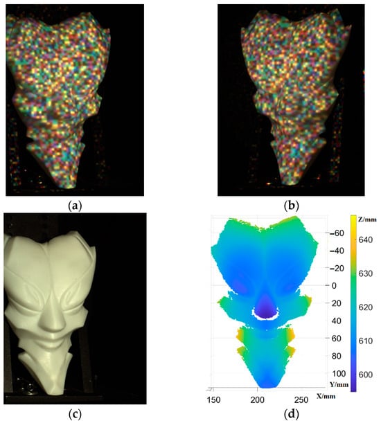
Figure 8.
The reconstruction of a mask. (a) object left view. (b) object right view. (c) original mask model image. (d) reconstructed point cloud.
Figure 9 shows the mesh model of the mask reconstructed from the point cloud using the Poisson reconstruction algorithm. It demonstrates the surface morphology of the mask effectively reconstructed by the algorithm proposed in this paper. Additionally, even with occlusion present around the nose area, erroneous points in the occluded region have been successfully removed. This validates the effectiveness of the algorithm in reconstructing objects with either no texture or sparse texture on their surfaces. To provide a closer view of the highlighted region in Figure 9b and compare it with the model image, as shown in Figure 10, it displays the restored details of the model’s eyes, mouth, and forehead.
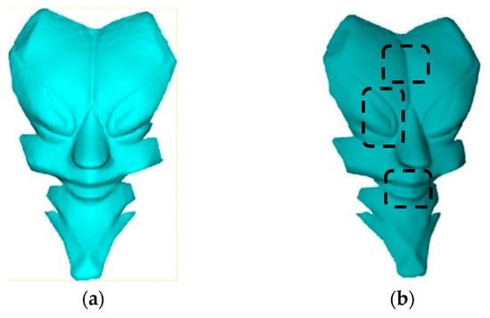
Figure 9.
The mesh reconstruction of a mask. (a) mesh view 1. (b) mesh view 2. The part within the dashed box will be enlarged in Figure 10.
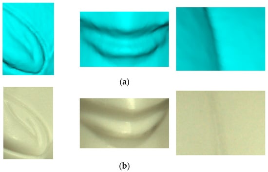
Figure 10.
Comparison of mask mesh details. (a) details of mask mesh. (b) details of original mask model image.
Figure 11 shows the image of the reconstruction experiment of the captured fan blades. The texture information on the surface of the fan blades is relatively sparse compared to the mask. However, unlike the mask, the fan blades’ different blades are in different planes, resulting in discontinuity in disparity. From the reconstruction results, it can be observed that the reconstruction algorithm proposed in this paper performs well for objects with discontinuous planes, providing good reconstruction results for regions with disparity discontinuity.
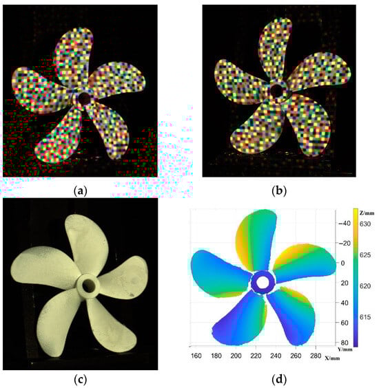
Figure 11.
The reconstruction of fan blades. (a) object left view. (b) object right view. (c) original fan blades image. (d) reconstructed point cloud.
As the blades belong to discontinuous planes, the mesh representation cannot adequately capture their surface features. Therefore, only the point cloud results are shown for the fan blades.
The proposed method in this paper is also applicable to depth acquisition in dynamic scenes. We performed a 3D reconstruction of the human hand, which is a highly complex and flexible dynamic object. The human hand has a complex structure consisting of multiple joints, and its surfaces often feature repetitive textures. This poses significant challenges for depth acquisition and 3D reconstruction.
However, through the method described in this paper, we successfully achieved an accurate 3D reconstruction of the human hand, as shown in Figure 12. We not only captured the macroscopic shape of the hand but also accurately reproduced even the smallest textures and details. As the human hand is a dynamic object, we did not capture the original images of the hands during the experiment.
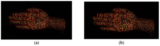
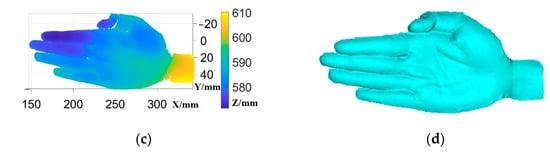
Figure 12.
The reconstruction of a human hand. (a) object left view. (b) object right view. (c) reconstructed point cloud. (d) reconstructed mesh.
This paper also delves into the reconstruction of the human face. Compared to the hands, the human face exhibits more intricate surface details. However, challenges arise due to factors like the eyebrow, which complicate the reconstruction process. Implementing the method proposed in this paper for facial reconstruction yields remarkable results in restoring the intricate details of the face, including the eyes, nose, and mouth, as shown in Figure 13.
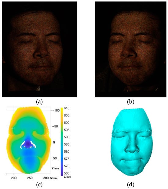
Figure 13.
The reconstruction of a human face. (a) object left view. (b) object right view. (c) reconstructed point cloud. (d) reconstructed mesh.
5. Conclusions
This paper presents a colored structured light encoding method for dense 3D reconstruction. Initially, a speckle-structured light pattern is designed that facilitates the extraction of color features, addressing the issue of repetitive speckles by incorporating De Bruijn path pruning. The method also eliminates the need for projector calibration and color correction, simplifying both the three-dimensional reconstruction process and system development. Experimental results have confirmed the accuracy and effectiveness of the method. Obtaining high-precision and dense point clouds for the surface measurement of industrial parts has been a persistent challenge. The method proposed in this paper has the potential for sparse texture reconstruction as it can obtain dense point clouds without the need for additional image acquisition, based on certain prior conditions. Future work will continue to investigate the reconstruction performance of this method on highly reflective objects and apply it to the surface reconstruction of industrial parts with complex surfaces.
Author Contributions
Conceptualization, S.L. and W.L.; methodology, S.L.; software, S.L.; validation, S.L.; formal analysis, S.L.; writing—original draft preparation, S.L.; writing—review and editing, W.L. All authors have read and agreed to the published version of the manuscript.
Funding
This research received no external funding.
Institutional Review Board Statement
The Studies involving human participants were reviewed and approved by School of Engineering Science, University of Science and Technology of China Institutional Review Board.
Informed Consent Statement
Informed consent was obtained from all subjects involved in this study.
Data Availability Statement
Data are contained within the article.
Conflicts of Interest
The authors declare no conflicts of interest.
References
- Rukundo, O. Challenges of 3D Surface Reconstruction in Capsule Endoscopy. J. Clin. Med. 2023, 12, 4955. [Google Scholar] [CrossRef] [PubMed]
- Yang, Y.; Ren, Y.X.; Chen, M.; Arita, Y.; Rosales-Guzmán, C. Optical trapping with structured light: A review. Adv. Photonics 2021, 3, 034001. [Google Scholar] [CrossRef]
- Zhang, F.; Prisacariu, V.; Yang, R.; Torr, P.H. Ga-net: Guided aggregation net for end-to-end stereo matching. In Proceedings of the IEEE/CVF Conference on Computer Vision and Pattern Recognition, Long Beach, CA, USA, 15–20 June 2019; pp. 185–194. [Google Scholar]
- Xu, G.; Cheng, J.; Guo, P.; Yang, X. Attention concatenation volume for accurate and efficient stereo matching. In Proceedings of the IEEE/CVF Conference on Computer Vision and Pattern Recognition, New Orleans, LA, USA, 18–24 June 2022; pp. 12981–12990. [Google Scholar]
- Han, C.; Li, M.; Zhang, C.; Yang, H. Color classification for structured light of De Bruijn based on clustering analysis. Recent Adv. Comput. Sci. Inf. Eng. 2012, 5, 359–364. [Google Scholar]
- Chen, H.; Wang, G.; Xue, J.H.; He, L. A novel hierarchical framework for human action recognition. Pattern Recognit. 2016, 55, 148–159. [Google Scholar] [CrossRef]
- Cui, Y.; Schuon, S.; Chan, D.; Thrun, S.; Theobalt, C. 3D shape scanning with a time-of-flight camera. In Proceedings of the 2010 IEEE Computer Society Conference on Computer Vision and Pattern Recognition, San Francisco, CA, USA, 13–18 June 2010; pp. 1173–1180. [Google Scholar]
- Chiang, P.J.; Lin, C.H. Active stereo vision system with rotated structured light patterns and two-step denoising process for improved spatial resolution. Opt. Lasers Eng. 2022, 152, 106958. [Google Scholar] [CrossRef]
- Geng, J. Structured-light 3D surface imaging: A tutorial. Adv. Opt. Photonics 2011, 3, 128–160. [Google Scholar] [CrossRef]
- Zhang, S. Recent progresses on real-time 3D shape measurement using digital fringe projection techniques. Opt. Lasers Eng. 2010, 48, 149–158. [Google Scholar] [CrossRef]
- Zhang, J.; Zhou, C.; Wang, X. Three-dimensional profilometry using a Dammann grating. Appl. Opt. 2009, 48, 3709–3715. [Google Scholar] [CrossRef] [PubMed]
- Han, W.; Yin, J.; Shen, J. Self-Supervised Monocular Depth Estimation by Direction-aware Cumulative Convolution Network. In Proceedings of the IEEE/CVF International Conference on Computer Vision, Paris, France, 2–6 October 2023; pp. 8613–8623. [Google Scholar]
- Lally, E.; Gong, J.; Wang, A. Method of multiple references for 3D imaging with Fourier transform interferometry. Opt. Express 2010, 18, 17591–17596. [Google Scholar] [CrossRef] [PubMed]
- Wang, Y.; Zhang, S. Superfast multifrequency phase-shifting technique with optimal pulse width modulation. Opt. Express 2011, 19, 5149–5155. [Google Scholar] [CrossRef] [PubMed]
- Gorthi, S.S.; Rajshekhar, G.; Rastogi, P. Investigation to realize a computationally efficient implementation of the high-order instantaneous-moments-based fringe analysis method. Opt. Eng. 2010, 49, 065802. [Google Scholar] [CrossRef]
- Zheng, X.; Yang, J.; Wang, R.; Lan, T. Visible light waveband Dammann grating based on all-dielectric metasurface. Appl. Opt. 2022, 61, 2184–2191. [Google Scholar] [CrossRef]
- Zhou, P.; Zhu, J.; You, Z. 3-D face registration solution with speckle encoding based spatial-temporal logical correlation algorithm. Opt. Express 2019, 27, 21004–21019. [Google Scholar] [CrossRef]
- Ye, J.; Zhou, C. Time-resolved coded structured light for 3D measurement. Microw. Opt. Technol. Lett. 2021, 63, 5–12. [Google Scholar] [CrossRef]
- Li, C.; Zhou, C.; Miao, C.; Yan, Y.; Yu, J. Binocular vision profilometry for large-sized rough optical elements using binarized band-limited pseudo-random patterns. Opt. Express 2019, 27, 10890–10899. [Google Scholar] [CrossRef] [PubMed]
- Liu, K.; Zhou, C.; Wei, S.; Wang, S.; Li, S.; Li, Y.; Wang, J.; Lu, Y. Binocular three-dimensional measurement system using a Dammann grating. In Proceedings of the Holography, Diffractive Optics, and Applications VI, Beijing, China, 9–11 October 2014; SPIE: Bellingham, WA, USA, 2014; Volume 9271, pp. 85–92. [Google Scholar]
- Zhong, F.; Kumar, R.; Quan, C. A cost-effective single-shot structured light system for 3D shape measurement. IEEE Sens. J. 2019, 19, 7335–7346. [Google Scholar] [CrossRef]
- Mittal, A.; Sofat, S.; Hancock, E. Detection of edges in color images: A review and evaluative comparison of state-of-the-art techniques. In Proceedings of the International Conference on Autonomous and Intelligent Systems, Aveiro, Portugal, 25–27 June 2012; Springer: Berlin/Heidelberg, Germany, 2012; pp. 250–259. [Google Scholar]
- Yu, X.; Wang, Y.; Yu, S.; Cheng, H.; Sun, X.; Yu, S.; Chen, D. 3D measurement method based on combined temporal encoding structured light. In Proceedings of the Sixth International Symposium on Precision Mechanical Measurements, Guiyang, China, 8–12 August 2013; SPIE: Bellingham, WA, USA, 2013; Volume 8916, pp. 565–572. [Google Scholar]
- Yadav, S.; Biswas, M. Improved color-based K-mean algorithm for clustering of satellite image. In Proceedings of the 2017 4th International Conference on Signal Processing and Integrated Networks (SPIN), Noida, India, 2–3 February 2017; IEEE: Piscataway, NJ, USA, 2017; pp. 468–472. [Google Scholar]
- Wang, Z.Z.; Yang, Y.M. Single-shot three-dimensional reconstruction based on structured light line pattern. Opt. Lasers Eng. 2018, 106, 10–16. [Google Scholar] [CrossRef]
Disclaimer/Publisher’s Note: The statements, opinions and data contained in all publications are solely those of the individual author(s) and contributor(s) and not of MDPI and/or the editor(s). MDPI and/or the editor(s) disclaim responsibility for any injury to people or property resulting from any ideas, methods, instructions or products referred to in the content. |
© 2024 by the authors. Licensee MDPI, Basel, Switzerland. This article is an open access article distributed under the terms and conditions of the Creative Commons Attribution (CC BY) license (https://creativecommons.org/licenses/by/4.0/).