
Review of Shale Oil and Gas Refracturing: Techniques and Field Applications
1
Oilfield Exploration and Development Department, Sinopec, Beijing 100728, China
2
Sinopec Jianghan Oilfield Petroleum Engineering Technology Reseach Institute, Wuhan 430035, China
3
State Key Laboratory of Oil and Gas Reservoir Geology and Exploitation, Chengdu University of Technology, Chengdu 610059, China
4
College of Energy, Chengdu University of Technology, Chengdu 610059, China
*
Author to whom correspondence should be addressed.
Processes 2024, 12(5), 965; https://doi.org/10.3390/pr12050965
Submission received: 11 March 2024
/
Revised: 6 May 2024
/
Accepted: 7 May 2024
/
Published: 9 May 2024
(This article belongs to the Special Issue Innovations in Hydraulic Fracturing Technology for Unconventional Reservoirs)
Abstract
:Shale oil and gas wells usually experience a rapid decline in production due to their extremely low permeability and strong heterogeneity. As a crucial technique to harness potential and elevate extraction rates in aged wells (formations), refracturing is increasingly employed within oil and gas reservoirs globally. At present, the selection processes for refracturing, both of wells and layers, are somewhat subjective and necessitate considerable field data. However, the status of fracturing technology is difficult to control precisely, and the difference in construction effects is large. In this paper, well selection, formation selection, and the fracturing technology of shale oil and gas refracturing are deeply analyzed, and the technological status and main technical direction of refracturing technology at home and abroad are analyzed and summarized. The applicability, application potential, and main technical challenges of existing technology for different wells are discussed, combined with the field production dynamics. The results show that well and layer selection is the key to the successful application of refracturing technology, and the geological engineering parameters closely related to the remaining reservoir reserves and formation energy should be considered as the screening parameters. General temporary plugging refracturing technology has a low cost and a simple process, but it is difficult to accurately control the location of temporary plugging, and the construction effect is very different. Mechanical isolation refracturing technology permits the exact refurbishment of regions untouched by the initial fracturing. However, it is costly and complex in terms of construction. Consequently, cutting the costs of mechanical isolation refracturing technology stands as a pivotal research direction.
1. Introduction
Shale formations have generally experienced multi-stage tectonic movements with frequent folding, fracture, uplift, and denudation, resulting in a high tectonic deformation intensity, complex geomorphic conditions, and great differences in preservation conditions [1]. Continental and marine–continental transitional facies with organic-rich shales demonstrate pronounced vertical and horizontal heterogeneity and exhibit substantial thermal evolution disparity. Continental shales typically showcase concurrent oil and gas characteristics. The high content of clay minerals in shale makes effective fracturing transformations challenging [2]. Shale reservoirs sport nano-sized pores with intense heterogeneity. Their flow is subtle at nanodarcy levels. Only through human intervention can the effective development of underground oil and gas be achieved [3]. Refracturing tech is key for aging wells to boost oil recovery. It provides a solid route to enhance shale reservoir exploration. This method is increasingly popular in oil and gas fields worldwide.
During the dawn of horizontal wells in shale reservoirs, technological constraints may have led to wells missing the sweet-spot areas. Moreover, initial completion along with the reservoir characteristics meant that the production wells fell short of reaching their true potential [3]. The innate heterogeneity of shale reservoirs often leads to uneven fracture propagation and suboptimal reservoir stimulation. When fractures are placed too closely, the high stress and strength interference can render some perforation clusters ineffective. This imbalance means that the full potential of the reservoir is not realized, and an extensive reconstruction is necessary to rectify the deficits. At the same time, due to the high-stress environment of shale reservoirs, the effective stress increases during the extraction, resulting in an increased closure pressure and an accelerated fracture closure, which reduce the permeability of the reservoir reconstruction area. The monitoring results after isobaric logging have shown that the local fracturing section did not produce gas, and about 1/3 of the perforating clusters did not produce gas or contributed little to gas production. However, the above under-utilized fracturing interval has great potential for secondary reconstruction [4].
In this paper, a deep dive is taken into the selection of wells and layers, alongside the fracturing technologies used in the refracturing of shale oil and gas. Furthermore, a comprehensive analysis and summary are conducted on the current landscape and primary technical trends of refracturing technology, both domestically and internationally. Combined with the field application in shale oil and gas areas such as the Fuling shale gas of Jianghan Oilfield, the applicability, application potential, and main technical challenges of unified temporary plugging and refracturing technology (temporary plugging ball, temporary plugging agent, etc.) and mechanical packer and refracturing technology (“solid casing in casing”, expandable liner, small-hole refracturing technology, etc.) for different wells are discussed. This conclusion can provide support for the refracturing optimization of shale gas wells in the future.
2. Basic Conditions of Refracturing
2.1. Well and Layer Selection Conditions
The key to refracturing technology lies in the selection of fracturing intervals. The selection of effective refracturing intervals and technical methods plays a key role in improving the production of shale gas wells [5,6,7,8]. After a large-scale reconstruction of shale gas reservoirs, the artificial fracture network and the distribution of remaining reserves in the fracturing of old wells are non-uniformly distributed, as shown in Figure 1. Laterally, microseismic monitoring results show that the scope of the reconstruction between wells is complex, and the distribution of fractures in single wells and single stages varies greatly [9]. According to the implementation effect of refracturing, the efficiency of refracturing (net present value) varies greatly in different basins and wells [10,11]. The reason is that the effect of refracturing is highly related to the scientificity of well and layer selection and the proper choice of fracturing time. Therefore, the basic conditions of refracturing must be fully evaluated when making refracturing decisions.
Well selection and layer selection by refracturing are relatively complicated processes because the conditions of each candidate well are different, and the selection basis is closely related to the reservoir properties, the initial stimulation effect, and the production conditions of the candidate well [12]. Robust wellbore conditions lay the groundwork for successful refracturing operations. Wells with a strong material base and a high reservoir pressure are foundational for such endeavors. Reservoirs suffering from extensive damage, along with wells plagued by serious fluid buildup, sand, or scale, are prime refracturing prospects. In the initial fracturing, wells that had suboptimal perforation parameters or were subjected to lower technological standards—evidenced by an imperfect fracturing fluid system, a scanty infusion of sand, or overly spaced fracturing stages—are also ideal candidates. Notably, wells that exhibit an impressive initial production but then experience a rapid decline are marked for potential refracturing benefits [13,14,15,16,17,18,19,20]. In addition, the candidate well should have a reasonable distance from the adjacent well and no severe pressure collusion with the adjacent well, and the horizontal section should not cross the fault. At present, the industry has not reached a consensus on the choice of refracturing time. The refracturing time is generally between 1 and 8 years, most of these values being concentrated between 1 and 4 years, and the production of some wells has decreased to 15% or less of the initial production before refracturing [13]. There are many factors that affect the effect of refracturing, and there is interaction among these factors. Therefore, it is necessary to comprehensively evaluate the impact of these factors on the effect of refracturing [21].
After years of exploration, the refracturing selection principles for shale oil and gas wells in North America include the following aspects [13]:
- (1)
- There are sufficient remaining reserves around the candidate well with a high initial production.
- (2)
- The well structure meets the requirements of refracturing construction, the wellbore diameter allows the running of fracturing tools, and the quality of production casing cementing can ensure the isolation between layers. Pumped bridge plug perforation completion is the best way to complete refracturing candidate wells due to the full diameter of the horizontal section and annular cement isolation.
- (3)
- The initial productivity of candidate wells is lower than expected due to non-reservoir factors such as the initial fracturing design and the construction technology, such as an imperfect fracturing fluid system, a small amount of sand added to fracturing, and excessive fracturing stage spacing and cluster spacing.
- (4)
- Due to the improper selection of nozzle size in the production process, the production decline is too fast, resulting in the premature closure of formation cracks.
- (5)
- Due to the sand and scale formation of the wellbore during the production process, the subsequent production capacity is lower than expected.
- (6)
- The candidate well has a reasonable distance from the adjacent well, there is no serious pressure collusion with the adjacent well, and the horizontal section does not cross the fault.
- (7)
- Before the infill well is drilled but not yet fractured, the mother well should be refractured first to restore the formation pressure around the mother well, and then the infill well should be fractured to reduce the phenomenon of the asymmetric expansion of the infill well fracture to the side of the mother well due to the pressure shortfall of the mother well, which can not only increase the output of the infill well but also protect the output of the mother well [13].
2.2. Well and Layer Selection Method
At present, several mainstream refracturing well selection methods are recognized in the industry [22]: The National Gas Research Institute (GTI) Method, The U of T at Austin Method, the SLB Method, the Weatherford Method, the estimated ultimate recovery (hereinafter referred to as EUR) method, and the simulation method. Based on the analysis of six mainstream well selection methods, the remaining reservoir reserves and formation energy of a single well target correspond to the material base and energy base of refracturing, respectively, which are the core and key factors affecting the effectiveness of the reconstruction.
There are many factors affecting the effect of refracturing, including the scale of pre-fracturing reconstruction, the degree of recovery, and the water cut. At the same time, there is interaction between these factors. Therefore, it is necessary to comprehensively evaluate the influence of these factors on the refracturing effect. Therefore, many scholars have carried out a lot of research on the key link of refracturing well selection based on a lot of research and practice on refracturing technology. At present, the more mature refracturing well selection methods recognized by Chinese and foreign scholars include the field experience method, the fuzzy comprehensive evaluation method, the neural network method, and the reservoir numerical simulation method.
However, in the actual application process, these methods have, more or less, different problems:
- (1)
- The subjectivity of the field experience method is strong, which can easily lead to deviation in the evaluation results.
- (2)
- The fuzzy comprehensive evaluation method selects refracturing wells mainly through fuzzy identification, membership degree theory, and the European proximity degree between each well and refracturing ideal wells. The fuzzy comprehensive evaluation method also relies on the accumulation of expert experience and has a certain subjectivity.
- (3)
- The neural network method involves complex hyperparameter adjustment and its training process has high requirements on field data, and a large number of refracturing wells with different effects need to be selected as learning and training samples. It is difficult to establish a reliable neural network model if there are few pre-fracturing wells in a target block.
- (4)
- The reservoir numerical simulation rule is based on the static and dynamic data of the gas reservoir after the initial fracturing, simulates the influence of various factors on the refracturing effect, and adopts mathematical statistical methods to make refracturing decisions. The reservoir numerical simulation method has very high requirements for reservoir geological modeling and involves complex mathematical calculation, which leads to high time costs and makes it difficult to meet the needs of rapid on-site evaluation.
To tackle the aforementioned challenges, the Roussel N.P. method for well and layer selection employs an enhanced algorithm that integrates multiple correlated factors [23]. This algorithm is refined by the inclusion of two additional parameters: drainage volume and instantaneous recovery degree, which serve as indicators of fracture quality from the initial fracturing. This approach leads to a more thorough and comprehensive consideration of various influential factors. In addition, there is a refracturing well selection method based on Pearson’s correlation coefficient. The evaluation parameters include reservoir parameters (reservoir span, effective reservoir thickness, reservoir porosity, reservoir permeability, well-controlled reserves, etc.), fracturing parameters (construction rate, sand strength, fluid strength, etc.), and production dynamic parameters (cumulative oil production and water cut). Using these parameters, Pearson’s correlation coefficient can be calculated, and the higher the correlation coefficient, the greater the potential of refracturing [24,25,26,27,28].
3. Refracturing Process
Shale oil and gas refracturing technology is mainly divided into general temporary plug refracturing technology (temporary plug ball, temporary plug agent, etc.) and mechanical packer refracturing technology (“sleeve in sleeve”, expandable liner, small-hole refracturing technology, etc.), and the fracturing materials are basically the same as the first fracturing. The general temporary plugging refracturing technology has a low cost and a simple process [29,30]. However, the challenge of precisely controlling the temporary plugging positions results in highly variable construction outcomes. On average, the intensity of sand addition and liquid usage in refracturing operations is on par with that seen in the initial fracturing efforts. The mechanical packer refracturing technology can effectively control the direction of the liquid and accurately transform the area not modified in the initial fracturing. However, the cost is high, and the construction process is complex. Compared with the first fracturing, the average sand and liquid strength of refracturing are generally doubled, and the segment spacing and cluster spacing are generally reduced by 40~50%. Construction displacement is reduced by about 50% due to reduction in the bore diameter. The specific process selection of refracturing should be based on the geological, engineering, and production dynamics characteristics of the target well, and the appropriate refracturing technology should be selected on the basis of EUR effective prediction and cost accounting.
3.1. Refracturing Technique
3.1.1. General Temporary Plug Refracturing Technique
When performing generalized refracturing using the original wellbore, to effectively modify both the initially fractured cluster of fractures or the newly induced clusters between existing fractures, it is typically necessary to force the fracturing fluid and propping agents into different clusters by adding temporary plugging balls or agents. This method of modification is referred to as generalized temporary plugging refracturing.
The effective sealing treatment of the initially fractured cracks poses a major challenge for generalized temporary plugging refracturing. The mechanism of crack redirection after temporary plugging is shown in Figure 2. Its mechanism of action mainly includes the following:
- (1)
- In-crack redirection. First, small-particle-size temporary plugging agents are injected, and, after entering a certain depth of the crack, they form a protective layer with the propping agent that can withstand a certain pressure, forcing the crack to redirect and communicate with previously unmodified areas.
- (2)

3.1.2. “Nested Casing” Refracturing Technology
The “nested casing” mechanical isolation refracturing technology involves inserting a smaller casing into the original wellbore to cement the well, mechanically isolating the perforation holes from the initial fracturing, and then performing segmented perforation and fracturing steps identical to the initial modification after creating a new channel within the wellbore, as shown in Figure 3. Based on the study of remaining reserve distribution, refracturing perforation can also be divided into two types: re-perforation between clusters or the re-perforation of old holes.
“Nested casing” refracturing is a type of fracturing method that involves inserting a smaller casing into the original casing. This technology has the following technical characteristics [32]:
- (1)
- The casing size is small, resulting in significant wellbore pressure loss and a limited construction scale.
- (2)
- The near-wellbore fracture network system causes severe fluid loss, leading to difficulties in sand addition.
- (3)
- The initial fracturing cracks can interfere with the propagation and expansion of new fracturing cracks, affecting the refracturing process.
- (4)
- The implementation cost of the process is high, and the process is complex, but it can completely seal the existing perforation holes and precisely control the initiation location and the direction of the fracturing fluid.
3.1.3. Expandable Liner Refracturing of Wellbore Technology
Addressing the issue of uncontrollable fracturing fluid flow direction caused by chemical temporary plugging agents in refracturing operations, Enventure GT has developed an expandable liner wellbore-reconditioning tool for refracturing [35]. After inserting the expandable liner into the desired location for sealing, high-pressure fluid is pumped through the wellhead to move the expansion cone and inflate the liner. The outer sealing device of the liner is set on the casing to form mechanical isolation and sealing. The old production zone and the original perforation cluster are isolated by the outer sealing mechanism, ensuring internal pressure integrity of the wellbore [36]. This is shown in Figure 4.
Expandable liner refracturing has the following characteristics [37]:
- (1)
- The original perforated section is isolated by the outer sealing mechanism of the liner, ensuring the internal pressure integrity of the wellbore.
- (2)
- For production zones which have been isolated by the expanded liner, refracturing operations can be conducted following the same procedures as the initial fracturing.
- (3)
- It reduces the complex operation of mechanical sealing with packers and liners, thus lowering costs.
- (4)
- It increases the available space in the wellbore after isolation, facilitating the insertion of larger fracturing equipment during the subsequent construction. The use of traditional packers and liners can significantly reduce the effective internal diameter of the wellbore for subsequent fracturing operations.
3.1.4. Slimhole Refracturing Technology
“Packers Plus Energy Services” has developed the Slimhole refracturing technology [38]. This technology involves inserting a liner into the existing wellbore and combining it with packers and sliding sleeves for refracturing operations. It is suitable for both open-hole and cased-hole completions, as shown in Figure 5 and Figure 6.
To sum up, the general temporary plugging and refracturing technique reinvigorates existing wells via strategic substance insertion, conquering the challenge of initial fracture sealing. The “nested casing” refracturing technology relies on internal structural reinforcement to bypass pre-existing perforations, thus crafting an avenue for intensive resuscitation of well production. The expandable liner refracturing of wellbore technology arises as a formidable contender to chemical agents, offering a directional dominion of fracturing fluids and stout mechanical isolation. On another front, the slimhole refracturing technique, developed by Packers Plus, introduces versatile configurations apt for varied well architectures, standing out in maintaining and optimizing wellbore real estate without compromising the refracturing’s repeatable nature. Each refracturing innovation narrates the saga of pushing operational boundaries and probing for methods that harmonize with the geological narrative, remaining reserves, and the practical tapestry of oilfield operations.
3.2. Refracturing Process Design
3.2.1. Generalized Temporary Plugging and Refracturing Process
Based on the principle of particle size grading, temporary plugging agents are typically composed of different combinations of particle sizes. Firstly, large-particle-size temporary plugging agents are used to form a bridging structure, followed by the injection of smaller-particle-size temporary plugging agents into the gaps between the larger ones, creating a dense sealing layer which enhances the plugging effect. Experimental measurements have shown a permeability range of 0.03 to 2.70 μm2. These temporary plugging agents are usually made of biodegradable materials such as polylactic acid (PLA), with particle sizes ranging from 8 to 200 mesh. After refracturing, they naturally degrade, restoring the gas production contribution of the sealed fractures, and the temporary plugging layer formed by the agents can withstand pressures up to 25.5 MPa [39].
The temporary plugging and refracturing process is commonly used in foreign shale gas wells. Generally speaking, the process is performed in stages on-site. Temporary plugging balls or agents are added to distinguish between different stages, allowing different stages to target different cluster locations. A typical generalized temporary plugging and refracturing operation consists of the following stages: pre-pad fluid pressurization stage, temporary plugging agent injection stage, refracturing stage, and re-injection of temporary plugging agent stage. The injection of pre-pad fluid can supplement the formation energy, increase the formation pressure in low-pressure areas, and avoid the extension of fractures entirely in low-pressure regions. Due to the low density of temporary plugging agents, pump discharge rates need to be controlled during the injection stage to prevent the agents from being pumped into the deep parts of the fractures. On the one hand, this can avoid temporary plugging agents from being pumped into the deep parts of the fractures; on the other hand, the reduced discharge rate can decrease the fracture width, facilitating the bridging and sealing of different particle sizes of temporary plugging agents within the fractures [40].
Generally speaking, as the construction progresses, the construction pressure and instantaneous pump shutdown pressure gradually increase, indicating that the fracture is constantly diverting and that new modification areas are being added. However, some scholars believe that, even if the construction pressure gradually increases, it does not necessarily indicate that the refracturing has diverted into new areas. For example, in a shale gas well in the Woodford block, the construction pressure gradually increased, but there was basically no increase in the post-fracturing production [30]. Agharazi et al. [41] argue that, in the presence of many perforated clusters, it is difficult for refracturing to generate new fractures. As gas continues to be produced after the initial fracturing, Mohr’s circle of formation rocks shifts to the right, increasing the effective stress acting on the weak planes of the rocks, thus making it more difficult to generate new fractures.
3.2.2. “Nested Casing” Refracturing Technology Process
When using the “nested fracturing” method for refracturing, it is necessary to optimize the wellbore structure and fracturing fluid properties [42]. For shale gas wells with longer wellbore lengths, fluid friction resistance largely determines the fracturing efficiency, which further affects the fracturing effect. Therefore, refracturing wells need to minimize the length of the inner small casing [43]. Generally speaking, only small casings are inserted into the horizontal well section for cementing, while the vertical well section still uses the original casing. Additionally, due to the reduced borehole size, it is recommended to choose delayed crosslinked gels and high-viscosity slickwater as fracturing fluids to reduce friction resistance. At the same time, due to the complex fracture network system after the initial fracturing, the fluid loss during refracturing increases, leading to narrower fracture widths and difficulties in placing proppants. Therefore, it is necessary to adjust the pumping rate and viscosity of the fracturing fluid in real time during the pumping process to reduce the risk of fracturing operations.
3.2.3. “Nested Casing” Refracturing Technology
There are significant differences in the construction process of the expandable liner refracturing technology, and the main construction steps include the following [44]:
- (1)
- Design of the External Seal Mechanism
The external seal mechanism refers to the elastomer surrounding the outer wall of the liner. After the liner is expanded, the elastomer is squeezed by the expanded liner and forms sufficient contact with the inner wall of the outer casing, serving to anchor the liner and isolate the old formation. During refracturing, the leakage points of the fracturing fluid in shale gas wells are mainly concentrated at the heel of the horizontal section and the original perforated section. Therefore, when performing expandable liner construction, in addition to installing liners with elastic sealing mechanisms at both ends of the original perforation positions based on the initial completion construction data to achieve sealing of the old production zones, multiple elastic sealing mechanisms should also be installed at the heel of the horizontal well to prevent fluid leakage and avoid affecting the construction effect.
- (2)
- Borehole Cleaning
During the scraping process, water containing calcium carbonate, plugging materials, and polymers is fully circulated inside the well to reduce the flow of fracturing fluid into the old perforations. The fluid inside the well needs to be continuously circulated until the returned material is clean (Figure 7).
- (3)
- Inserting and Expanding the Liner
During the insertion of the liner, an appropriate amount of lubricant can be added to the fluid inside the well to reduce the probability of sticking and the degree of wear during the process of inserting the expanded liner into the horizontal section. Once the liner string reaches the predetermined position in the horizontal section, the expansion process begins, as shown in Figure 8. During the expansion process, it is important to maintain a moderate expansion rate, ranging from 4.0 to 9.0 m/min. The inside of the pipe needs to be evenly coated with a high-temperature-resistant and water erosion-resistant lubricating grease to reduce friction between the expansion cone and the inner wall of the liner, lower the pressure required to drive the expansion cone, and increase the success rate of liner expansion.
- (4)
- Low-Pressure Testing and Drilling Accessories
The wellhead is closed, and a pressure test is conducted on the upper well section. The purpose of the test is to verify whether the strength and sealing performance of the vertical well section and the heel of the horizontal well meet the requirements for fracturing. After the liner is expanded, the bottom plug remains inside the liner, and, at this point, it is necessary to use a milling drilling tool combination to remove the bottom plug and through hole.
- (5)
- Full-well Pressure Testing, Perforation, and Fracturing
The wellhead is closed, and a target pressure test is conducted on the entire well section. The purpose of the test is to verify whether the pressure system of the entire wellbore after sealing off the old production zones has sufficient sealing performance and strength to withstand the high pressure of fracturing. After sealing off the old production zones, refracturing operations are carried out according to the requirements of perforation and fracturing design. During fracturing, the expanded liner is used as a fracturing string and needs to repeatedly withstand extremely high fracturing pressures. After fracturing is completed, the expanded liner will also be used as a production string during the remaining production cycle of the shale gas well.
To reduce the construction difficulty and cost of this technology, and, considering that most temporary plugging agents and fracturing fluids will leak at the heel of the horizontal well, Enventure GT has proposed a new mixed concept, which is to only place the expandable liner at the heel of the horizontal well. This method will reduce the usage of temporary plugging agents and better transmit the pressure generated by the cracks to the heel of the horizontal well [36,37].
3.2.4. Slimhole Refracturing Technology Process
There are two technical specifications for small wellbore refracturing. Depending on the outer diameters of the casing strings, which are ϕ114.0 mm and ϕ139.7 mm, two different liner diameters of ϕ73.0 mm and ϕ88.9 mm are used, respectively. These liners are paired with sliding sleeve-blocking balls of different diameters to perform different stages of refracturing operations. Depending on the specifications, the diameter differences of the sliding sleeve-blocking balls can be divided into two types: ϕ3.18 mm and ϕ1.59 mm. The maximum construction capability can reach up to 32 stages.
According to the process, applicability, advantages and disadvantages of each technology, it is sorted into a table for convenient comparison and optimization, as shown in Table 1.
4. Field Application
4.1. General Temporary Plug Refracturing
4.1.1. Haynesville Case [31]
In the Haynesville block, generalized temporary plugging and refracturing operations were conducted on 15 wells. Prior to the fracturing design, the parameters for perforation optimization were adjusted based on the conditions of each well. When the cluster spacing was between 15.2 and 18.3 m, and the number of clusters per stage was greater than six, based on a previous process analysis, there were multiple perforation clusters that were not fully stimulated. Due to the larger cluster spacing, additional perforation operations could be performed to simultaneously address the clusters that had not been fully stimulated during the initial fracturing. For wells which had already been fractured with an even larger cluster spacing in the early stages and with fewer clusters per stage, the initial fracturing was relatively sufficient. Therefore, optimization of the perforation location was conducted based on geological steering logging results, and additional perforation operations were performed to focus on the new perforations for refracturing.
During the initial stage of fracturing, considering the severe pressure decay in the fully stimulated perforation clusters, clean water was first pumped to restore the formation pressure. Subsequently, as the production proceeded, the pressure inside the fractures decreased in the fully stimulated perforation clusters, and the fluid conductivity decreased due to proppant embedment. Therefore, crosslinked fracturing fluid carrying proppants was pumped to further enhance its fluid conductivity. Then, temporary plugging agents were pumped to seal the already-filled perforation clusters. After that, crosslinked fracturing fluid carrying proppants was injected, and temporary plugging agents were pumped at each stage to fill both the old and new fractures. Finally, a mixed fracturing operation mode of “slickwater and gel fluid” was conducted.
A production analysis was conducted on the 15 wells. Wells BD2 and BD11 experienced interference from neighboring wells during production, resulting in errors in the calculation of the EUR. The improvement in the EUR ranged from (0.08) × 108 m3 to (0.8) × 108 m3. Due to the production duration, the production data of BD14 and BD15 did not meet the EUR prediction requirements. However, based on the production test results, compared to the original production data, the initial production increased by 40% and 7%, respectively. A specific comparison of the production capacities is shown in Figure 9.
4.1.2. Eagle Ford Case
In December 2016, refracturing operations were conducted on two wells, A1 and A2, in the Eagle Ford block. Before the refracturing, an additional 59 clusters of perforations were added to wells A1 and A2, increasing the total number of clusters per well from 60 to 119. Prior to the fracturing operation, 4293 m3 of clean water was pumped at a pressure of 48.3 MPa to restore the pressure, followed by sand-adding operations using crosslinked fracturing fluid. Through multi-stage temporary plugging, the old and new fractures were fully stimulated.
Well A1 received a total of 28,461.0 m3 of fracturing fluid, 2724.0 tons of proppants, and 1113 temporary plugging balls. Stages 1 to 12 used temporary plugging agents, while stages 13 to 32 used temporary plugging balls. The number of balls per stage increased from 40 to 90. Well A2 received a total of 16,536.0 m3 of fracturing fluid, 1135.0 tons of proppants, and 388 temporary plugging balls. In stage 14, the number of temporary plugging balls per stage was increased to 95, and, due to a high operating pressure, the flow rate was adjusted on-site.
After the refracturing, construction was carried out on the infill well B3. Through the refracturing operations on wells A1 and A2, a fracturing enhancement under different numbers of temporary plugging balls was obtained as shown in Figure 10. This slowed down the depletion of formation pressure in the already-stimulated areas, favoring the redirection and extension of new fractures in the infill well B3 towards the unstimulated regions.
The production capacity before and after refracturing is shown in Figure 11. After the refracturing of well A1, the production recovered to 61% of the initial production, and the EUR increased by 36%. For well A2, after refracturing, the production recovered to 46% of the initial production, and there was no significant change in the EUR.
4.1.3. Fuling Case
The shale gas wells in the Fuling shale gas reservoir have exhibited a significant decline in production over time, necessitating the need for refracturing to enhance the recovery rate of the gas field [46]. In terms of temporary plugging and refracturing technology, Sinopec has conducted on-site trials at several wells in the Fuling shale gas reservoir, demonstrating the feasibility of this technology. However, close attention needs to be paid to the evaluation of potential wells before fracturing and the issue of wellbore plugging after fracturing.
For the F19 well, the first six sections of 395.00 m underwent four stages of temporary plugging and refracturing, with a total fluid volume of 10,970.9 m3 and a total sand volume of 319.2 m3. A total of 668 temporary plugging balls and 430.0 kg of temporary plugging agent were used. The operating pressure ranged from 58.0 to 97 MPa, and the shutdown pressure was between 32.8 and 38.8 MPa. Before refracturing, the daily gas production was (0.5 to 0.6) × 104 m3, which was similar to the pressure transmission. After refracturing, the test pressure was between 8.0 and 9.0 MPa, and the test production was (5.1 to 5.4) × 104 m3, as shown in Figure 12. The good increase in production after refracturing confirms the feasibility of the refracturing process.
For the F39 well, the first 10 sections underwent six stages of “temporary plugging balls and temporary plugging agent” refracturing. The total fluid volume was 17,166.7 m3, the total sand volume was 684.0 m3, 659 temporary plugging balls were used, and 2100.0 kg of temporary plugging agent was applied. Before the refracturing and shutdown of the well, the cumulative gas production was 2097.5 × 104 m3, and the daily gas production was 0.2 × 10⁴ m3, as shown in Figure 13. However, after refracturing, the wellbore was blocked by pollutants, limiting the effectiveness of the post-fracturing results.
Well F20 completed a five-stage “temporary plugging balls and temporary plugging agent” refracturing operation across its entire well section, which consisted of 15 sections. The total fluid volume used during the operation was 15,571.9 m3, and the total sand volume was 407.4 m3. During construction, a total of 395 temporary plugging balls were added, 309 of which were 13.5 mm, 60 were 11 mm, and 16 were 9.5 mm. Due to the increased well section length of 1404 m, the operational difficulty was heightened compared to the previous two wells. The fracturing of the entire well section reduced the impact of single-stage processing on production, and the subsequent production capacity depended on the overall potential of the refracturing operation well. After refracturing, the well experienced a slight increase in production, with a daily gas production of 2.0 × 10⁴ m3, as shown in Figure 14.
In the early stage of the Fuling shale gas reservoir, a ball-dropping temporary plugging process was used to carry out refracturing operations on three shale gas wells. During the construction process, a phenomenon of gradually increasing pressure was observed, indicating severe near-wellbore fluid loss [47]. After fracturing, the maximum increase in recoverable reserves was 0.10 × 10⁸ m3. The production profiles showed that gas production contributions were concentrated in the heel section, indicating that multi-stage fracturing repeatedly modified the heel fracturing section. However, the use of ball-dropping temporary plugging could not effectively mobilize the entire well section. Currently, the limitations of ball-dropping temporary plugging for refracturing are relatively strong [47].
4.2. “Nested Casing” Refracturing
4.2.1. Haynesville Case
Since 2016, the technology of rebuilding wellbore and refracturing has been applied on a large scale in the Haynesville shale gas field in the United States. By inserting a ϕ117.0 mm casing into the original wellbore to rebuild it, large-scale fracturing operations have been achieved [43].
According to the statistical data shown in Figure 15, there are significant differences in the construction parameters among the 75 rebuilt wellbore refracturing operations in the Haynesville shale gas field in the United States. The average sand intensity for the first fracturing is between 1.8 and 1.9 t/m, while the average sand intensity for refracturing is between 4.8 and 4.9 t/m, representing an average increase of more than 160%. The average fluid intensity for the first fracturing is between 16.0 and 17.0 m3/m, while the average fluid intensity for refracturing is between 32.0 and 33.0 m3/m, showing an increase of over 100%. The average length of the first fracturing stage is between 88.0 and 91.0 m, while the average length of the refracturing stage is between 46.0 and 49.0 m, representing a decrease of more than 48%. The average cluster spacing for the first fracturing is between 15.0 and 16.0 m, while the average cluster spacing for refracturing is between 9.0 and 9.5 m, indicating a decrease of over 40%. The construction differences are mainly reflected in the construction displacement, which is primarily influenced by the length of the new casing and the degree of pressure drop in the production reservoir during the early stage. The displacement for refracturing is mainly concentrated between 5.0 and 8.0 m3/min, showing a significant decrease compared to the first fracturing [48].
Overall, there is a relatively poor correlation between the first fracturing construction parameters and the post-refracturing production capacity. However, there is a more significant correlation between the refracturing construction parameters and the production capacity. Among them, the sand intensity and the fluid intensity have a weaker correlation with the post-refracturing production capacity, but the overall usage is almost doubled compared to the first fracturing. The correlation between the stage cluster division and perforation location and the post-refracturing production capacity is more evident. Effectively reducing the stage cluster spacing has improved the production effectiveness after refracturing.
4.2.2. Eagle Ford Case
The successful implementation of refracturing technology in the Haynesville shale gas field in the United States has also been promoted and applied in the Eagle Ford shale gas field. The Eagle Ford shale field in the United States has refractured 37 rebuilt wells, with the highest refracturing effect resulting in an increase of nearly 17 times in production. As shown in Figure 16, the EUR analysis of refracturing for five wells indicated an increase of nearly 140% compared to the initial fracturing EUR per well.
4.2.3. Fuling Case
Since 2020, the Fuling shale gas reservoir has successfully conducted “casing-in-casing” refracturing tests in wells such as F4, F20, and F2. The transformation effect has been steadily improving, and the construction cost per meter has continued to decrease, laying a solid foundation for the promotion and application of the technology.
The F4 well carried out a pilot test of “casing-in-casing” refracturing, with 21 stages and 80 clusters of fracturing construction. The post-fracturing test production was 18.38 × 10⁴ m3/d. The post-fracturing test production of the F20 well was 8.81 × 10⁴ m3/d. The post-fracturing test production of the F2 well was 17.67 × 10⁴ m3/d, achieving good transformation results. The current production data require further tracking (Figure 17).
As of 13 February 2023, China’s first “casing-in-casing” refracturing gas well using fully domestically produced technological processes, tools, and materials, i.e., the F5-1 well, successfully completed all construction tasks. It achieved a high-yield industrial gas flow rate of 14.2 × 10⁴ m3/d, with a test production which recovered to 75% of the initial fracturing. The construction cost decreased by 29% compared to the initial stage, marking a breakthrough in the field of “casing-in-casing” rebuilt wellbore refracturing for shale gas in China, breaking foreign restrictions. This provides an effective reference for the development and production increase in old shale gas fields in China.
4.3. Expandable Liner Refracturing of Wellbore
Refracturing with expandable liners was conducted in one well in the Bone Spring formation of the Permian Basin. The well was drilled and fractured in 2012 [39]. Before the fracturing operation, the artificial lift equipment was removed, and a retrievable bridge plug was installed at the design depth to test the integrity of the ϕ139.7 mm casing. Once the casing integrity was confirmed to meet the requirements for subsequent operations, the well was washed, and an expandable liner was run to the design depth. Lubricants were added to the well fluid during the liner running process to reduce the chances of the expandable liner getting stuck or worn out in the horizontal section. Once the liner reached the predetermined position in the horizontal section, it was inflated by applying pressure. Subsequently, a pressure test was conducted throughout the well section, reaching a test pressure of 42.8 MPa. The test was successful, and a 22-stage hydraulic fracturing treatment was carried out on the 1005.84 m horizontal section. The sand addition met the design objectives, and there were no issues with poor sealing during the fracturing process. The test production before and after refracturing is shown in Figure 18. The initial production increased by approximately 100%, and the predicted EUR increased by nearly 200%, demonstrating significant effectiveness.
4.4. Slimhole Refracturing Technology
This technology has been successfully applied in the Montney shale formation of the Septimus gas field in Canada. The test well had a measured depth of 3400.04 m, a vertical depth of 2043.07 m, and a horizontal section length of 1284.12 m. It was completed with a ϕ114.0 mm wellbore. A total of five stages of fracturing were performed, with the first two stages using sand-jetting perforation fracturing and the last three stages using pump-delivered bridge plug perforation combined fracturing. During the initial fracturing operation, a total of 2648.1 m3 of fracturing fluid was injected, with an average proppant usage of 120.0 tons per stage and a maximum displacement rate of 6.0 m3/min.
A ϕ73.0 mm small wellbore was inserted into the existing wellbore, and, combined with packers and sliding sleeves, 10 stages of refracturing were performed. Compared to the initial fracturing, the usage of fracturing fluid increased by 7523.6 m3, and the proppant usage per stage increased by 70.0 tons. The maximum displacement rate for refracturing was 9.5 m3/min, which was higher than the initial fracturing rate of 6.0 m3/min. The maximum pump pressure for slickwater operation was 63.5 MPa. Five months after refracturing, the average natural gas production was 74.6 × 10⁴ m3 (converted based on a conversion coefficient of 1 ton of oil equivalent to 1255 m3 of natural gas equivalent), which was an increase of three times compared to the pre-fracturing production of 18.7 × 10⁴ m3.
Currently, refracturing techniques have been broadly applied around the world with considerable success. The general temporary plugging and refracturing technique has been successfully deployed in the Haynesville and Eagle Ford regions of the United States as well as in the Fuling shale gas field in China. By optimizing parameters such as cluster spacing and hole patching and selecting appropriate pre-fracture water volumes, crosslinking fluids, and temporary blocking agents, engineers have successfully enhanced the flow capacity of production wells and created new fracture pathways. The “nested casing” refracturing technology, by installing a new casing within the original wellbore and performing refracturing operations, has significantly improved the fracturing efficiency. In the Haynesville and Eagle Ford regions of the United States, a substantial increase in the amount of sand and fracturing fluid, along with reduced cluster spacing, have resulted in a significant increase in the potential ultimate recovery (EUR). Additionally, the application of this technology in China’s Fuling shale gas field has demonstrated potential for reducing costs and increasing the production capacity, as well as fostering the development of domestic processes, breaking the constraints of foreign technology, and providing practical cases and strategic experiences for the redevelopment of domestic old oil and gas fields. The expandable liner refracturing of wellbore technology and the slimhole refracturing techniques have shown significant effects in enhancing the recovery rates. For instance, in the Bone Spring formation, the reconstruction of a wellbore with expandable casing and a subsequent 22-stage hydraulic fracturing operation doubled the initial production rate and nearly doubled the predicted EUR. Meanwhile, the application in Canada’s Montney formation has shown that slimhole refracturing not only increased the use of proppant and discharge rates but also significantly boosted well productivity, tripling the output of the initial fracturing.
Different cases demonstrate that refracturing can significantly improve production and the estimated ultimate recovery (EUR). These instances prove the vital role of this technology in increasing the recovery rate of shale gas wells, extending the life of wellfields, and maximizing resource utilization. Although some technical challenges such as wellbore blockage and pressure management exist, they can be effectively overcome with meticulous engineering design and execution. Overall, temporary plugging refracturing provides a significantly effective and widely applicable solution for enhancing the productivity of unconventional oil and gas deposits.
5. Economic Evaluation of Refracturing
There are significant differences in the effectiveness and economics of refracturing among different blocks in North America, as well as between different wells within the same block. In terms of transformation effects, shale blocks such as Eagle Ford, Bakken, and Marcellus have relatively good results. Eagle Ford is expected to have a five-year oil increment ranging from (0.08) × 104 m3 to (3.82) × 104 m3, with an expected EUR of 0.71 to 2.85 times the initially fractured estimated ultimate cumulative production [13].
In terms of fracturing investment, the lumped temporary plugging refracturing process has an investment of approximately USD 500,000 to USD 1.5 million per well, while the liner refracturing process has an investment of approximately USD 3 million to USD 4 million per well. The profit is generally twice that of lumped refracturing, but it also faces higher operational risks.
In terms of transformation benefits, the net present value range of oil well increments in the Bakken region is between negative USD 1.5 million and USD 10.5 million, with a fracturing efficiency of 86%; the net present value range of oil wells in the Eagle Ford region is between negative USD 2.6 million and USD 9.3 million, with a refracturing efficiency of 56% for oil wells.
The Fuling shale gas reservoir initially adopted the lumped temporary plugging refracturing process to carry out pilot tests on three shale gas wells. After fracturing, the maximum recoverable reserves increased by 0.10 × 10⁸ m3 [34]. The production profiles showed that gas production contributions were concentrated in the heel section, and effective utilization of the entire wellbore could not be achieved through temporary plugging steering. At this stage, the lumped temporary plugging refracturing process had strong limitations [34]. Later, four shale gas wells were tested with the “casing-in-casing” refracturing process. The recoverable reserves of two wells increased from (0.08) × 108 m3 to (0.38) × 108 m3 after fracturing, while the production data of the other two wells require further tracking. The F5-1 well is the first well in China to adopt domestically produced technological processes, tools, and materials for the reconstruction of the wellbore and refracturing. The test production recovered to 75% of the initial fracturing, and the construction cost decreased by 29% compared to the initial stage. This provides an effective reference for the development and production increase in old shale gas fields in China.
6. Conclusions
- Wellbore conditions are fundamental to successful refracturing operations. Wells with good material foundations, a high reservoir pressure, significant reservoir damage, severe wellbore fluid accumulation, sanding and scaling issues, unreasonable initial fracturing perforation parameters, low process parameters, and high initial production rates that decline rapidly can be considered prime candidates for refracturing.
- Shale oil and gas refracturing techniques primarily encompass two categories: lumped temporary plugging refracturing and mechanical isolation refracturing (including “casing-in-casing”, expandable liners, and slimhole refracturing techniques). The specific choice of technique should be tailored to the geological, engineering, and production dynamics characteristics of the target well. The most suitable refracturing technology should be selected based on effective EUR predictions and cost accounting.
- There are significant differences in the effectiveness and economics of refracturing among different blocks in North America or between different wells within the same block. The F5-1 well is the first well in China to adopt fully domestically produced technological processes, tools, and materials for the reconstruction of the wellbore and refracturing. It holds promise for providing valuable insights for the development and production increase in aging shale gas fields in China.
Overall, the successful application of refracturing technology hinges on careful well and layer selection. Geological and engineering parameters closely related to the remaining reservoir volume and formation energy should be considered as screening criteria. Lumped temporary plugging refracturing is cost-effective and straightforward but can have variable results due to difficulties in precise temporary plugging placement. Mechanical isolation refracturing allows for the precise modification of areas not addressed during the initial fracturing, but it is more expensive and complex. Reducing the cost of mechanical isolation refracturing is a key research focus.
Author Contributions
L.X., D.W. and L.L. developed the methodology and wrote the main manuscript. C.W., H.Z. and X.T. reviewed the manuscript. All authors have read and agreed to the published version of the manuscript.
Funding
This review is funded by the National Natural Science Foundation of China (NSFC) Youth Fund Project, No. 52204005, the Sichuan Provincial Outstanding Youth Science and Technology Talents Project, No. 2022JDJQ0007, the Sichuan Provincial Natural Science Foundation Youth Fund Project, No. 23NSFSC4652, and the NSFC Major Project Topic, No. 52192622, China Petroleum & Chemical Corporation Limited research project: Research on high-efficiency fracturing technology and its application in Fuling shale gas with few stages No. P23161, multiple clusters and on re-fracturing technology of shale gas horizontal well reconstruction No. P24153.
Data Availability Statement
Data are contained within the article.
Acknowledgments
We would thank all the editors and anonymous reviewers for their comments and suggestions.
Conflicts of Interest
Author Liru Xu is employed by the company Sinopec. Authors Dajiang Wang and Lizhi Liu are employed by the Petroleum Engineering Technology Research Institute of SINOPEC Jianghan Oilfield Company. The remaining authors declare that the research was conducted in the absence of any commercial or financial relationships that could be construed as a potential conflict of interest.
References
- Hu, D.; Zhang, H.; Ni, K.; Yu, G. Main controlling factors for gas preservation conditions of marine shales in southeastern margins of the Sichuan Basin. Nat. Gas Ind. 2014, 34, 17–23. [Google Scholar]
- Sun, H.; Zhou, D.; Cai, X.; Wang, F.; Feng, D.; Lu, T. Progress and prospect of shale gas development of Sinope. China Pet. Explor. 2020, 25, 14–26. [Google Scholar]
- Duan, X.; Wu, J.; Zhang, X.; Hu, Z.; Chang, J.; Zhou, S.; Chen, X.; Qi, L. Progress and key issues in the study of enhanced recovery of marine shale gas in Sichuan Basin. Acta Pet. Sin. 2022, 43, 1185–1200. [Google Scholar]
- Li, Y.; He, Y.; Xiao, J.; Shi, X.; Feng, Q.; Yin, C. Optimal selection and effect evaluation of refracturing intervals of shalegas horizontal wells. Nat. Gas Ind. 2018, 38, 59–64. [Google Scholar]
- Li, Y.; Wei, C.; Qin, G.; Li, M.; Luo, K. Numerical simulation of hydraulically induced fracture network propagation in shale formation. In Proceedings of the 6th International Petroleum Technology Conference, Beijing, China, 26–28 March 2013; pp. 26–28. [Google Scholar]
- Maxwell, S.C.; Urbancic, T.I.; Steinsberger, N.; Zinno, R. Micro-seismic imaging of hydraulic fracture complexity in the Barnett shale. In Proceedings of the SPE Annual Technical Conference and Exhibition, San Antonio, TX, USA, 29 September–2 October 2002. [Google Scholar]
- Meyer, B.R.; Bazan, L.W. A discrete fracture network model for hydraulically-induced fractures: Theory, parametric and case studies. In Proceedings of the SPE Hydraulic Fracturing Conference and Exhibition, The Woodlands, TX, USA, 24–26 January 2011; pp. 24–26. [Google Scholar]
- Mittal, R.; Oruganti, Y.D.; McBurney, C. Re-fracturing simulations: Pressure-dependent SRV and shear dilation of natural fractures. In Proceedings of the Unconventional Resources Technology Conference, San Antonio, TX, USA, 20–22 July 2015; pp. 20–22. [Google Scholar]
- Xiao, J.; You, Y.; Zhu, H.; Tang, X.; Zhang, F.; Liu, W. Key technologies for development adjustment well fracturing in Chongqing Fuling National Shale Gas Demonstration Area. Nat. Gas Ind. 2022, 42, 58–65. [Google Scholar]
- Barree, R.D.; Miskimins, J.L.; Svatek, K.J. Reservoir and completion considerations for the refracturing of horizontal wells. SPE Prod. Oper. 2018, 33, 1–11. [Google Scholar] [CrossRef]
- Oruganti, Y.; Mittal, R.; Mcburney, C.J.; Rodriguez, A. Re-fracturing in Eagle Ford and Bakken to increase reserves and generate incremental NPV: Field study. In Proceedings of the SPE Annual Technical Conference and Exhibition, Houston, TX, USA, 28–30 September 2015; p. SPE 173340. [Google Scholar]
- Yang, Z.; Li, Y.; Li, X.; Li, C. Key technology progress and enlightenment in refracturing of shale gas horizontal wells. J. Southwest Pet. Univ. 2019, 41, 75–86. [Google Scholar]
- Guang, X.; Wang, M. Refracturing key technologies of shale oil and gas in North America and the suggestions. Oil Drill. Prod. Technol. 2019, 41, 224–229. [Google Scholar]
- Jiang, T. A fuzzy method for selecting well and formation in refracting. Oil Drill. Prod. Technol. 1997, 19, 60–62. [Google Scholar]
- Zhou, Z.; Ma, H.; Xu, W.; Yu, X.; Liu, W.; Li, X. Appling fuzzy comprehensive judge method to identify deficient returing well. Math. Pract. Theory 2009, 39, 80–86. [Google Scholar]
- Zhang, W.; Liu, J.; Zhao, X.; Yang, J. Study on well selection and layer selection in Hujianshan Chang 4+5 reservoir by refracturing. Chem. Eng. Equip. 2015, 10, 132–137. [Google Scholar]
- Du, W. Artificial neural network method for well and layer selection in refracturing. Drill. Prod. Technol. 2003, 4, 117–118. [Google Scholar]
- Cheung, C.M.; Goyal, P.; Tehrani, A.S.; Prasanna, V.K. Deep Learning for Steam Job Candidate Selection. In Proceedings of the SPE Annual Technical Conference and Exhibition, San Antonio, TX, USA, 9–11 October 2017; p. SPE187339MS. [Google Scholar]
- Denney, D. Artificial Neural Networks Identify Restimulation Candidates. J. Pet. Technol. 2000, 52, 44–45. [Google Scholar] [CrossRef]
- Udegbe, E.; Morgan, E.; Srinivasan, S. From Face Detection to Fractured Reservoir Characterization: Big Data Analytics for Restimulation Candidate Selection. In Proceedings of the SPE Annual Technical Conference and Exhibition, San Antonio, TX, USA, 9–11 October 2017; p. SPE187328-MS. [Google Scholar]
- Liu, Z. Method for selecting refracturing wells in low permeability sandstone reservoirs based on pearson correlation coefficient. Pet. Geol. Recovery Effic. 2022, 29, 140–144. [Google Scholar]
- Cao, X. Application of temporary plug refracturing technology in oilfield. China Pet. Chem. Ind. Stand. Qual. 2022, 42, 11–14. [Google Scholar]
- Berchenko, I.; Detournay, E. Deviation of hydraulic fractures through poroelastic stress changes induced by injection and pumping. Am. Rock Mech. Assoc. 1997, 34, 1009–1019. [Google Scholar] [CrossRef]
- Mahmood, M.N.; Guo, B. An analytical method for optimizing fracture spacing in shale oil reservoirs. In Proceedings of the SPE Liquids-Rich Basins Conference—North America, Odessa, TX, USA, 7–8 November 2019; p. SPE197083. [Google Scholar]
- Huo, Y.; Jiang, H. A preferred method for gas well refracturing well based on BP neural network. Nat. Gas Geosci. 2020, 31, 552–558. [Google Scholar]
- Pankaj, P.; Gakhar, K.; Lindsay, G. When to refrac? Combination of reservoir geomechanics with fracture modeling and reservoir simulation holds the answer. In Proceedings of the SPE Asia Pacific Oil & Gas Conference and Exhibition, Perth, Australia, 25–27 October 2016; p. SPE182161. [Google Scholar]
- Ren, W.; Li, G.; Tian, S.; Sheng, M.; Geng, L. Analytical modelling of hysteretic constitutive relations governing spontaneous imbibition of fracturing fluid in shale. J. Nat. Gas Sci. Eng. 2016, 34, 925–933. [Google Scholar] [CrossRef]
- Sun, X. A refracturing candidate selection method based on fuzzy comprehensive evaluation. Sci. Technol. Innov. Her. 2008, 4, 80–81. [Google Scholar]
- Gumus, A.T.; Yayla, A.Y.; Celik, E.; Yildiz, A. A combined fuzzy-ahp and fuzzy-gra methodology for hydrogen energy storage method selection in Turkey. Energies 2013, 6, 3017–3032. [Google Scholar] [CrossRef]
- Grieser, B.; Calvin, J.; Dulin, J. Lessons learned: Refracs from 1980 to present. In Proceedings of the SPE Hydraulic Fracturing Technology Conference and Exhibition, The Woodlands, TX, USA, 9–11 February 2016; p. SPE179152. [Google Scholar]
- Cadotte, R.J.; Crowley, Z.; Elbel, B. Evaluation of cement-isolated casing liner and degradable particulate diverter refracturing treatments in the Haynesville shale. In Proceedings of the SPE Hydraulic Fracturing Technology Conference and Exhibition, The Woodlands, TX, USA, 23–25 January 2018; p. SPE189843. [Google Scholar]
- Allison, D.B.; Curry, S.S.; Todd, B.L. Restimulation of wells using biodegradable particulates as temporary diverting agents. In Proceedings of the Canadian Unconventional Resources Conference, Calgary, AB, Canada, 15–17 November 2011; p. SPE149221. [Google Scholar]
- Xiao, B.; Li, S.; Jiang, T.; Gao, D.; Bian, X. Research progress on temporary-plugging refracturing technology for shale gas wells. Sci. Technol. Eng. 2020, 20, 9707–9715. [Google Scholar]
- Tian, G. Sinopec shale gas horizontal well was successfully refractured for the first time. Nat. Gas Ind. 2017, 37, 98. [Google Scholar]
- Dong, S.; Jing, C.; Song, W.; Yang, L.; Luo, Y.; Duan, Y. Development and enlightenment of refracturing technology for horizontal shale gas wells in North America. Drill. Prod. Technol. 2022, 45, 98–102. [Google Scholar]
- Teng, C. Enventure GT introduces expandable liner refracturing technology. Pet. Drill. Tech. 2016, 44, 98. [Google Scholar]
- Luo, Y. Application Research of Expandable Tube Technology in Refracturing; China University of Petroleum: Beijing, China, 2021. [Google Scholar]
- Hlidek, B.; MacDonald, D.; Gee, C. Slimhole refracturing case studies and experience utilizing mechanical isolation for effective refracture treatments. In Proceedings of the SPE Low Perm Symposium, Denver, CO, USA, 5–6 May 2016; p. SPE180236. [Google Scholar]
- Yi, S.; Sharma, M. A model for refracturing operations in horizontal wells employing diverting agents. In Proceedings of the SPE Asia Pacific Hydraulic Fracturing Conference, Beijing, China, 24–26 August 2016; p. SPE181795. [Google Scholar]
- Morales, A.; Zhang, K.; Gakhar, K.; Porcu, M.M.; Lee, D.; Shan, D.; Malpanj, R.; Pope, T.; Sobernheim, D.; Acock, A. Advanced modeling of interwell fracturing interference: An Eagle Ford Shale oil study-refracturing. In Proceedings of the SPE Hydraulic Fracturing Technology Conference, The Woodlands, TX, USA, 9–11 February 2016; p. SPE179177. [Google Scholar]
- Agharazi, A.; Kashikar, S. A geomechanical study of refracturing based on microseismic observations-case study of Haynesville and Eagle Ford wells. In Proceedings of the SPE/AAPG/SEG Unconventional Resources Technology Conference, San Antonio, TX, USA, 1–3 August 2016; p. URTEC-2435484. [Google Scholar]
- Elbel, B.; Modeland, N.; Habachy, S.; Nabors, J.; Brannon, R. Evaluation of a casing-in-casing refracturing operation in the Burleson county Eagle Ford formation. In Proceedings of the IADC/SPE Drilling Conference and Exhibition, Fort Worth, TX, USA, 6–8 March 2018; p. SPE189644. [Google Scholar]
- Liu, Y.; Li, Y.; Ming, Y.; Xiao, J.; Han, R.; Wang, Z.; Zhang, J.; Wu, C. First successful application of casing in casing CiC refracturing treatment in shale gas well in China: Case study. In Proceedings of the Abu Dhabi International Petroleum Exhibition & Conference, Abu Dhabi, United Arab Emirates, 15–18 November 2021; p. SPE208060. [Google Scholar]
- Luo, Y.; Zhang, Q.; Guo, H.; He, F. Technology status and development for ESeal RF liner. Oil Field Equip. 2019, 48, 81–85. [Google Scholar]
- Mary, G.; Joshua, B.; James, P.; Pettigrew, S.; Elvig, K. An Eagle Ford case study: Improving an infill well completion through optimized refracturing treatment of the offset parent wells. In Proceedings of the SPE Hydraulic Fracturing Technology Conference and Exhibition, The Woodlands, TX, USA, 5–7 February 2019; p. SPE194374. [Google Scholar]
- Gomaa, A.M.; Nino-Penaloza, A.; Mccartney, E.; Mayor, J. Engineering solid particulate diverter to control fracture complexity. In Proceedings of the SPE Hydraulic Fracturing Technology Conference, The Woodlands, TX, USA, 9–11 February 2016; p. SPE179144. [Google Scholar]
- Liu, Y.; Ming, Y.; Zhang, X.; Bian, X.; Zhang, C.; Wang, H. “Casing in casing” mechanical isolation refracturing technology in Fuling Shale Gas Wells. Pet. Drill. Tech. 2022, 50, 86–91. [Google Scholar]
- Cadotte, R.J.; Elbel, B.; Modeland, N. Unconventional multiplay evaluation of casing-in-casing refracturing treatments. In Proceedings of the SPE International Hydraulic Fracturing Technology Conference and Exhibition, Muscat, Oman, 16–18 October 2018; p. SPE191451. [Google Scholar]
- Amrut, A.; Adebayo, O.; Carl, K.; Sunil, L.; Lisset, S. Refracturing technology restores profitability of older unconventional wells in Southeast New Mexico. In Proceedings of the SPE Hydraulic Fracturing Technology Conference and Exhibition, The Woodlands, TX, USA, 5–7 February 2019; p. SPE194372. [Google Scholar]
Figure 1.
Top view of microseismic monitoring event density and sweep characteristics [9].
Figure 1.
Top view of microseismic monitoring event density and sweep characteristics [9].
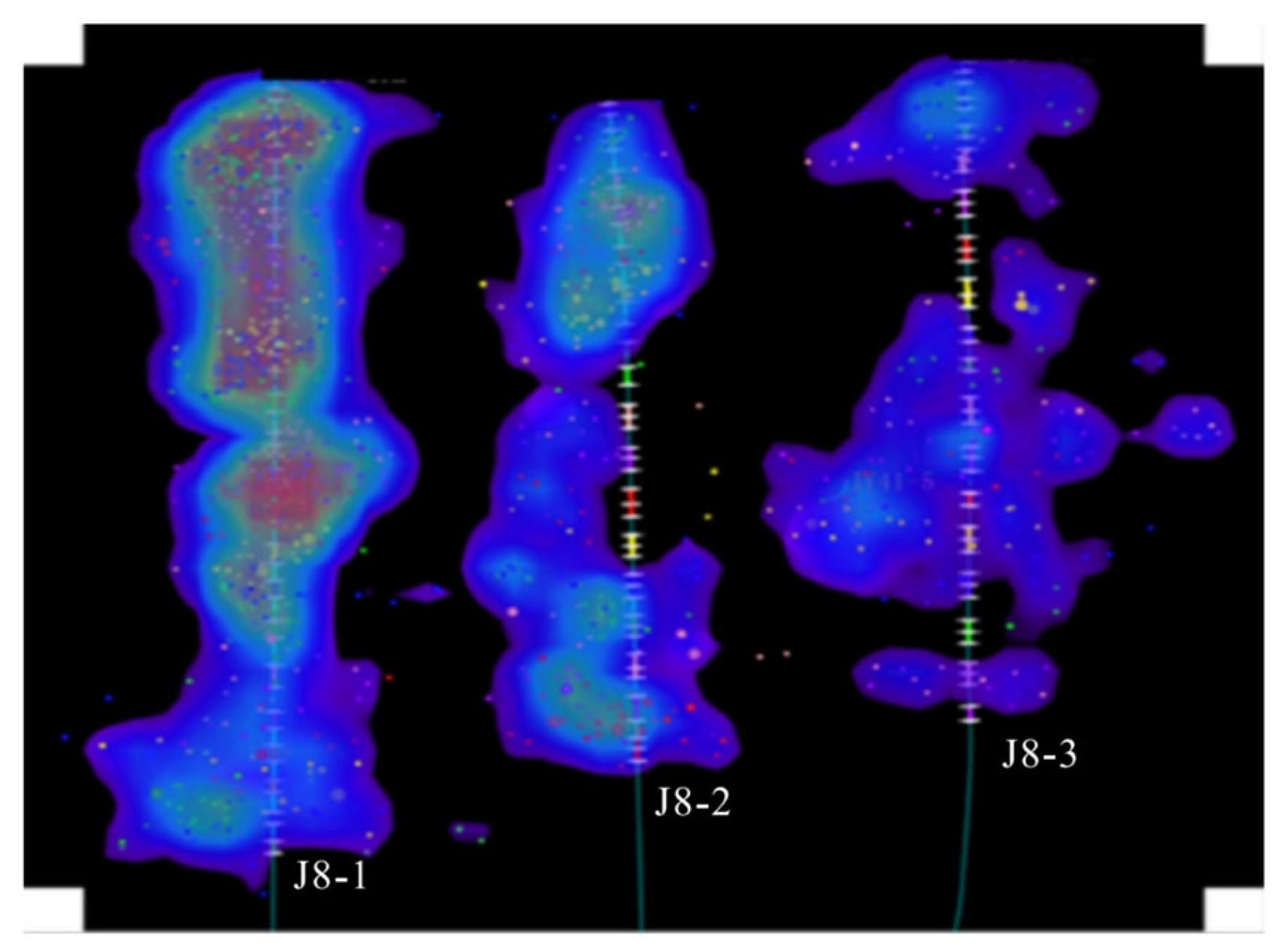
Figure 3.
Schematic diagram of the “nested casing” wellbore (Revised from [34]).
Figure 3.
Schematic diagram of the “nested casing” wellbore (Revised from [34]).
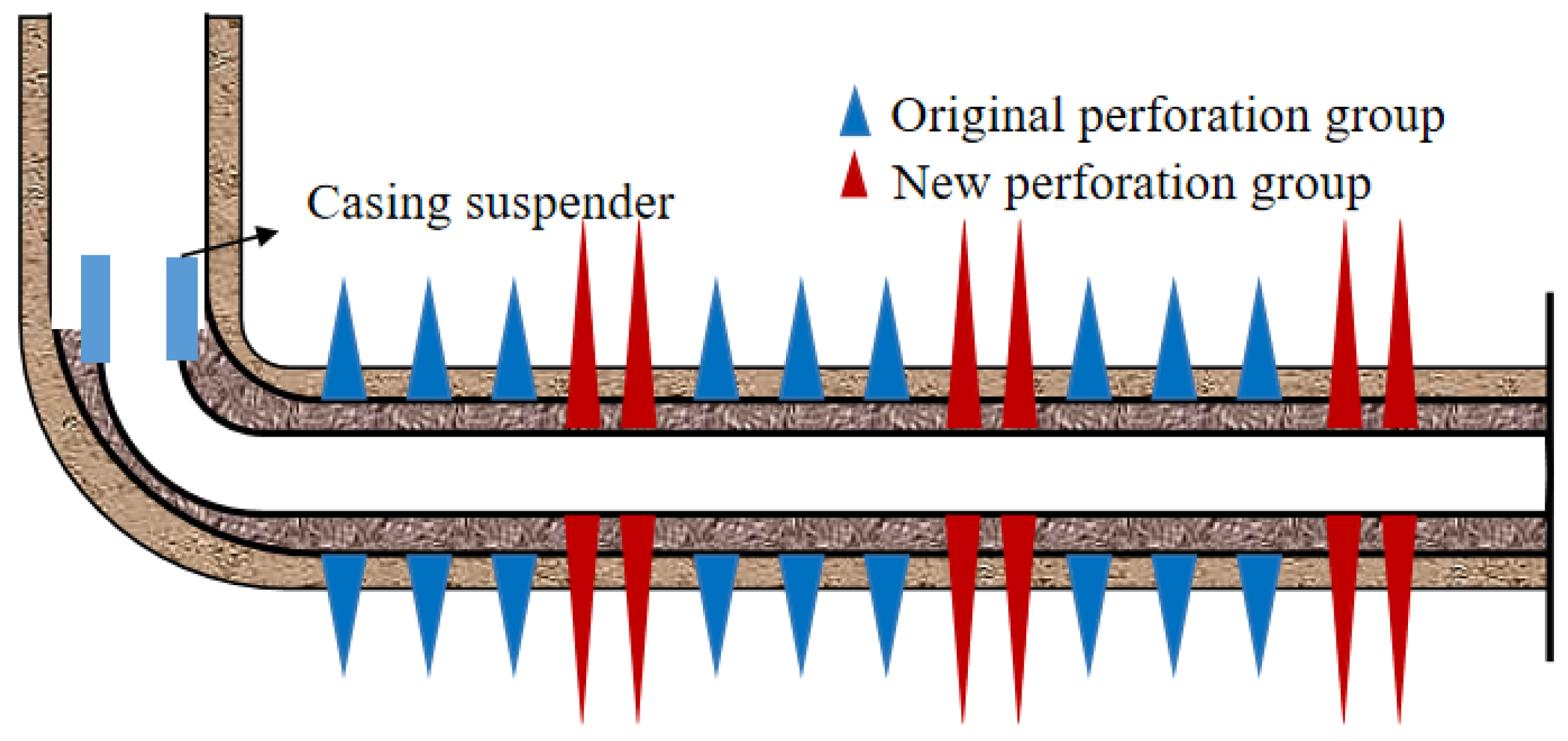
Figure 4.
Schematic diagram of expansion liner technology (Revised from [37]).
Figure 4.
Schematic diagram of expansion liner technology (Revised from [37]).
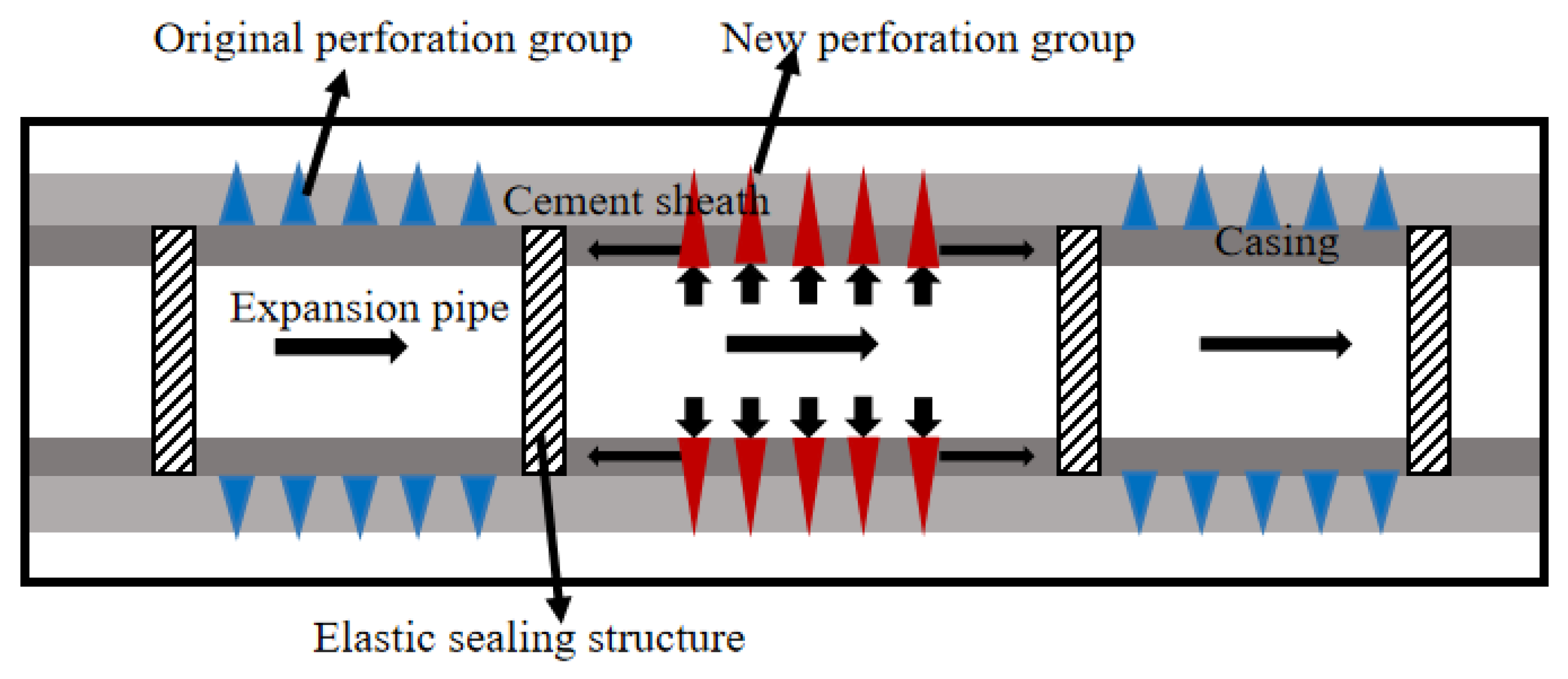
Figure 5.
Pipe string diagram under open-hole completion conditions (Revised from [38]).
Figure 5.
Pipe string diagram under open-hole completion conditions (Revised from [38]).

Figure 6.
Pipe string diagram under casing completion conditions (Revised from [38]).
Figure 6.
Pipe string diagram under casing completion conditions (Revised from [38]).

Figure 7.
Scraping tool assembly (Revised from [37]).
Figure 7.
Scraping tool assembly (Revised from [37]).

Figure 8.
Schematic diagram of the expansion process (Revised from [37]).
Figure 8.
Schematic diagram of the expansion process (Revised from [37]).
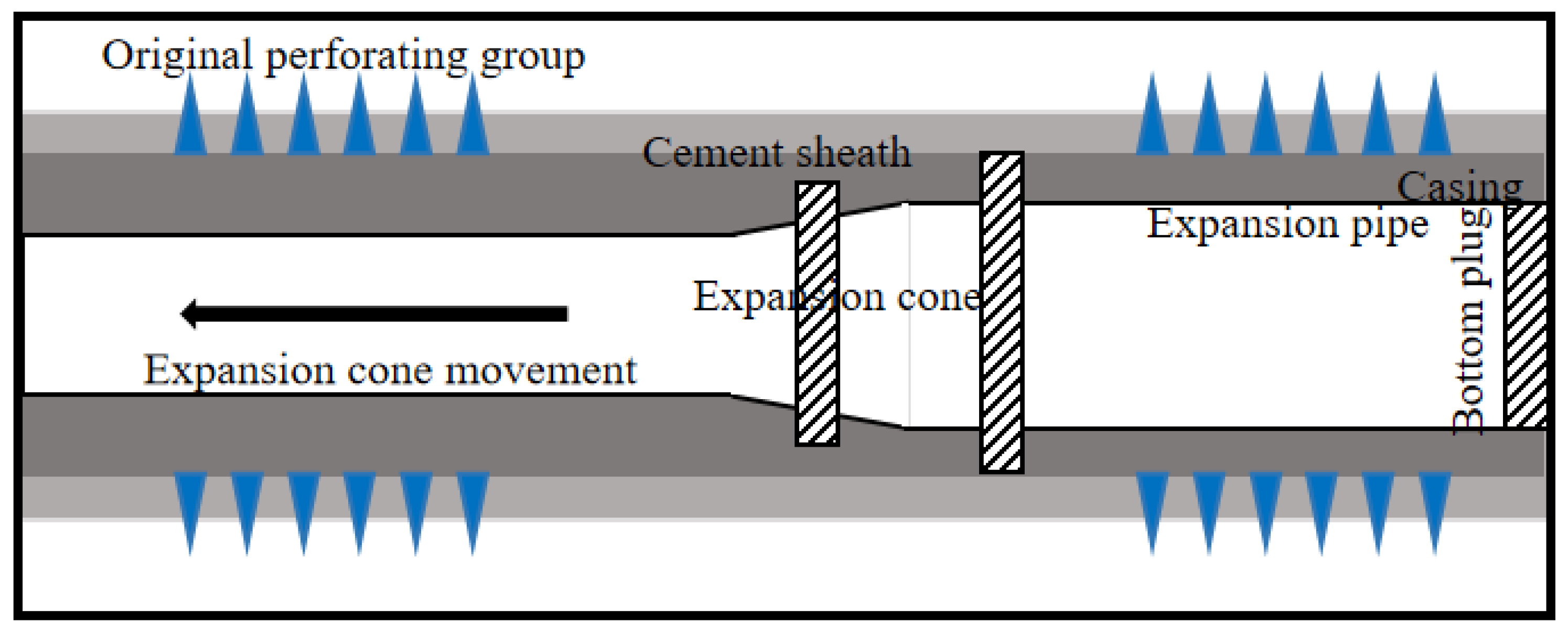
Figure 9.
Stimulation effect after large-scale refracturing (Revised from [31]).
Figure 9.
Stimulation effect after large-scale refracturing (Revised from [31]).
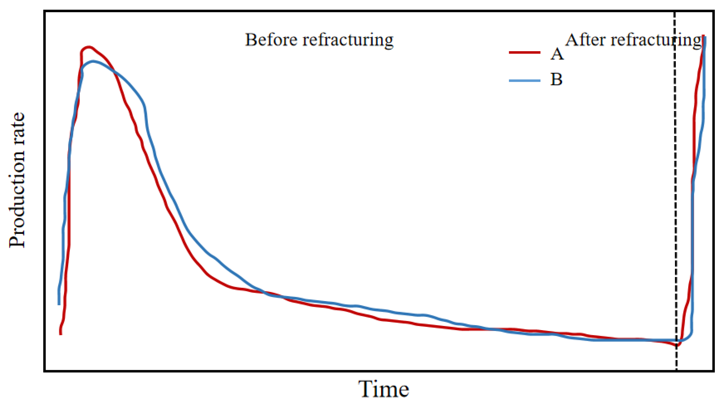
Figure 10.
Fracturing growth rate under different numbers of temporary plugging balls (Revised from [45]).
Figure 10.
Fracturing growth rate under different numbers of temporary plugging balls (Revised from [45]).
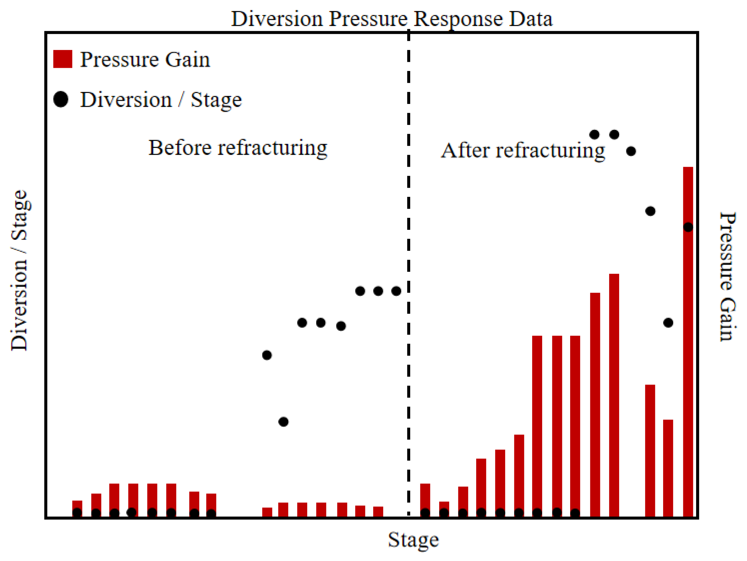
Figure 11.
Comparison of gas production before and after refracturing (Revised from [45]).
Figure 11.
Comparison of gas production before and after refracturing (Revised from [45]).
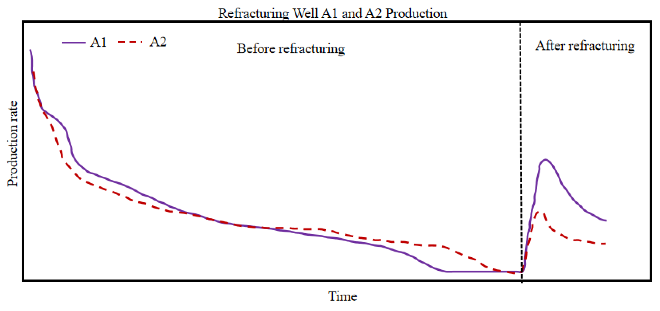
Figure 12.
F19 refracturing construction curve.

Figure 13.
F39 refracturing construction curve in Fuling shale gas reservoir.
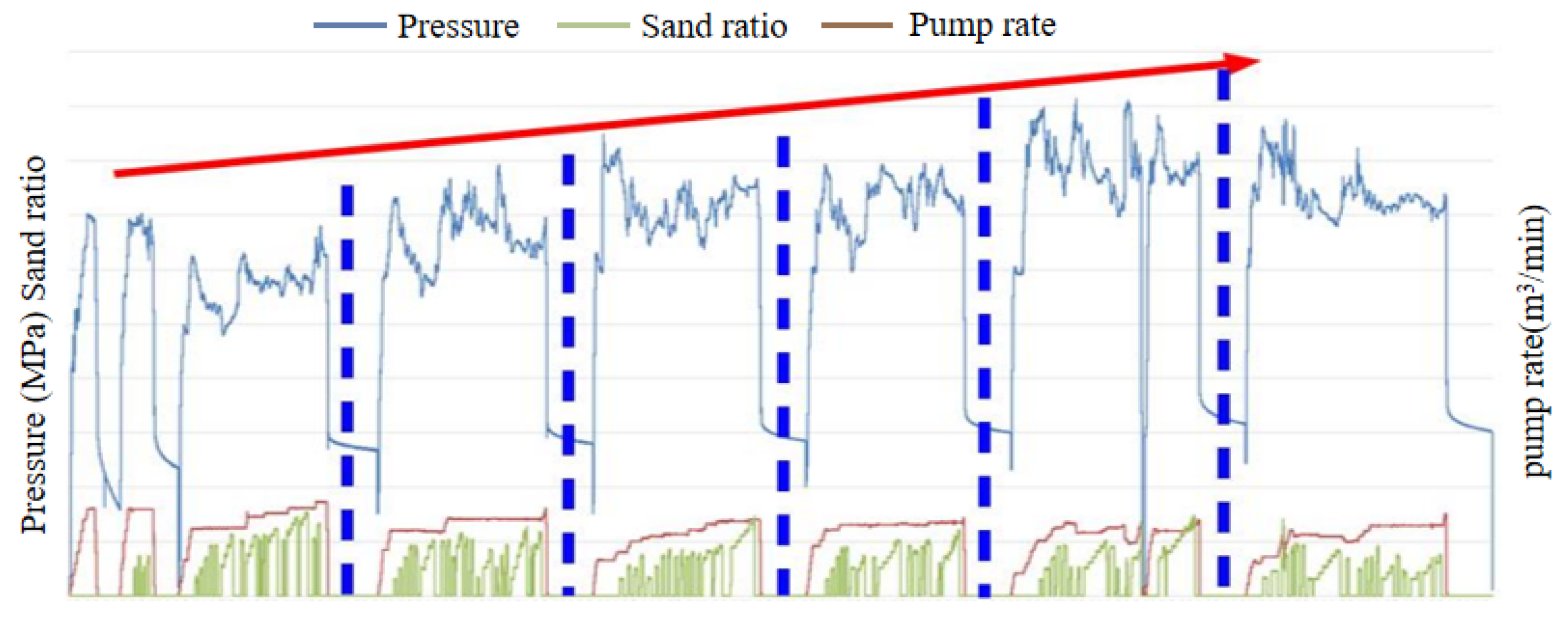
Figure 14.
Refracturing construction curve of F20 in Fuling shale gas reservoir.

Figure 15.
Correlation analysis between refracturing construction parameters and post-productivity in Haynesville shale gas field in the United States (Revised from [48]).
Figure 15.
Correlation analysis between refracturing construction parameters and post-productivity in Haynesville shale gas field in the United States (Revised from [48]).

Figure 16.
Comparison of 90-day normalized production before and after refracturing (Revised from [48]).
Figure 16.
Comparison of 90-day normalized production before and after refracturing (Revised from [48]).
Figure 17.
Comparison of test data of refracturing wells in Fuling shale gas reservoir. (a) Test pressure comparison of refractured wells. (b) Refractured well test production comparison.
Figure 17.
Comparison of test data of refracturing wells in Fuling shale gas reservoir. (a) Test pressure comparison of refractured wells. (b) Refractured well test production comparison.

Figure 18.
Production test of expandable liner before and after refracturing (Revised from [49]).
Figure 18.
Production test of expandable liner before and after refracturing (Revised from [49]).


Table 1.
Various fracturing processes, characteristics, and applicability.
| Refracturing Technique | Process | Applicability | Advantage | Disadvantage | |
|---|---|---|---|---|---|
| General temporary plug refracturing | By adding temporary plugging balls or temporary plugging agents, the fracturing fluid and proppant are forced to enter different fracture clusters. | When utilizing the original wellbore to carry out general repeat fracturing, the purpose is to effectively transform the newly drilled clusters in the primary fracturing cluster or between fractures. | Low technical cost and simple process. | It is difficult to precisely control the temporary plugging location, resulting in significant differences in the construction effects. The average sanding intensity and fluid intensity of repeat fracturing are generally comparable to those of the first fracturing. | |
| Mechanical isolation and refracturing technology | “Nested casing” refracturing | A small-sized casing is inserted into the original wellbore for cementing, and the perforations of the primary fracturing are mechanically sealed off. After a new channel is formed inside the wellbore, segmented perforation fracturing is performed again with the same steps as the primary transformation. | For horizontal well sections, small casings are inserted for cementing, while the original casing is still used in vertical well sections. | It can effectively control the flow direction of the fluid and accurately target areas that have not been successfully fractured during the initial fracturing operation. | The cost is relatively high, and the construction process is complex. Compared to the initial fracturing, the average sand concentration and fluid intensity for repeated fracturing generally increase by 100%, while the stage spacing and cluster spacing are typically reduced by 40% to 50%. Additionally, the construction flow rate is limited by the reduced wellbore diameter b0y approximately 50%. |
| Expandable liner refracturing of wellbore | After inserting the expandable liner into the position which needs to be sealed off, high-pressure fluid is pumped through the wellhead to move the expansion cone and cause the liner to expand. The external sealing device of the liner is seated on the casing, forming a mechanical isolation and seal. | For repeated fracturing operations, there is an issue with chemical temporary plugging agents being unable to control the flow direction of the fracturing fluid. | |||
| Slimhole refracturing technology process | Inserting a liner into the original wellbore and combining a packer and a sliding sleeve for repeated fracturing operations. | It is suitable for both open-hole and cased-hole completions. | |||
Disclaimer/Publisher’s Note: The statements, opinions and data contained in all publications are solely those of the individual author(s) and contributor(s) and not of MDPI and/or the editor(s). MDPI and/or the editor(s) disclaim responsibility for any injury to people or property resulting from any ideas, methods, instructions or products referred to in the content. |
© 2024 by the authors. Licensee MDPI, Basel, Switzerland. This article is an open access article distributed under the terms and conditions of the Creative Commons Attribution (CC BY) license (https://creativecommons.org/licenses/by/4.0/).
Share and Cite
MDPI and ACS Style
Xu, L.; Wang, D.; Liu, L.; Wang, C.; Zhu, H.; Tang, X. Review of Shale Oil and Gas Refracturing: Techniques and Field Applications. Processes 2024, 12, 965. https://doi.org/10.3390/pr12050965
AMA Style
Xu L, Wang D, Liu L, Wang C, Zhu H, Tang X. Review of Shale Oil and Gas Refracturing: Techniques and Field Applications. Processes. 2024; 12(5):965. https://doi.org/10.3390/pr12050965
Chicago/Turabian StyleXu, Liru, Dajiang Wang, Lizhi Liu, Chen Wang, Haiyan Zhu, and Xuanhe Tang. 2024. "Review of Shale Oil and Gas Refracturing: Techniques and Field Applications" Processes 12, no. 5: 965. https://doi.org/10.3390/pr12050965
Note that from the first issue of 2016, this journal uses article numbers instead of page numbers. See further details here.