
Energy Mutual Aid Device of Electric Vehicles: Quadratic Boost Converter with Modified Voltage-Mode Controller
College of Information Science and Engineering, Northeastern University, Shenyang 110819, China
*
Author to whom correspondence should be addressed.
Mathematics 2024, 12(10), 1531; https://doi.org/10.3390/math12101531
Submission received: 10 April 2024
/
Revised: 28 April 2024
/
Accepted: 11 May 2024
/
Published: 14 May 2024
(This article belongs to the Special Issue Mathematical Applications in Electrical Engineering)
Abstract
:Electric vehicles are becoming a mainstay of road transport. However, the uneven distribution of the electric vehicle charging piles in cities has led to the problem of “mileage anxiety”. This has become a significant concern of consumers in purchasing electric vehicles. At the same time, it also hinders the development of the electric vehicle industry. For this reason, this paper designs an electric vehicle energy mutual aid device. In the event that the power battery of an electric vehicle is low on energy and there are no suitable charging piles around, the device can also seek energy supplementation from surrounding electric vehicles with sufficient energy. This device should satisfy the characteristics of wide gain, high power, small size, and light weight. Firstly, the quadratic boost converter and its state space model are constructed. It uses only one electrical switching element to realize the light weight of the device, and it also provides wide voltage gain to fulfill the needs of electric vehicle charging. Secondly, an improved voltage mode controller is proposed to address the shortcomings of the conventional voltage mode controller of the quadratic boost converter. It avoids the tradeoff between the transient and steady-state performance due to the integration action of the conventional voltage mode controller. Also, this controller uses less feedback to make the controlled system output the required DC power, reducing the weight of the device. Finally, the effectiveness of the proposed energy mutual aid device is verified by simulations and experiments.
MSC:
94C601. Introduction
With the advancement of science and technology, there is a new international consensus to achieve sustainable social development. In recent years, the international community has further increased its attention regarding this issue in the face of the frequent occurrence of extreme weather and the deteriorating ecological environment [1]. Therefore, setting the goal of “peak carbon and carbon neutrality” and accelerating the energy transition will help governments to effectively promote the decarbonization of the consumption of energy. The development of clean and renewable energy and efforts to promote the optimization of the energy structure reduce fossil energy consumption [2]. As people become more environmentally conscious, they are realizing the serious pollution caused by conventional gasoline and diesel vehicles. The emergence of “zero-emission” electric vehicles has come into focus [3,4]. Governments worldwide have also strengthened their policies to promote the development of the electric vehicle industry [5,6]. According to the Global Electric Vehicle Perspective published by the International Energy Agency (IEA), the global electric vehicle fleet reached 16.5 million by the end of 2021, more than tripling compared to the end of 2018. China’s electric vehicles market is robust, with 3.3 million electric vehicles sold in 2021, accounting for more than 50 percent of the global market.
However, because there are many imperfections in the supporting facilities for electric vehicles, the convenience of electric vehicle charging is the first consideration for many consumers. At the same time, electric vehicle owners are worried about traveling long distances. Therefore, the problem of “mileage anxiety” [6] caused by the inadequate service facilities in the electric vehicle industry is not only a matter of concern for electric vehicle consumers but also a pain point and difficulty that electric vehicle companies and the industry urgently need to solve.
In the current market, some companies have developed devices to supply power to the external side of electric vehicles to remedy this situation. The existing devices have the disadvantages of high installation costs, limited charging locations, and poor adaptability. For example, Mitsubishi’s MiEV Power BOX was a device that could be used in conjunction with the company’s electric vehicles “i-MiEV”, “MINICAB-MiEV”, and “Outland”. This device was not only large but also complicated to use. The LEAF to Home device launched by the Nissan Motor Company also had the same function, but the device was also not easy to carry and complicated to use, and the installation price was as high as USD 2758. Therefore, it was not easy to promote the use of these devices on a large scale in practical situations. Based on this, the portable electric vehicle energy mutual aid device proposed in this paper can compensate for the devices’ shortcomings, as mentioned above, to ensure that consumers can realize effective vehicle–vehicle energy mutual aid.
Using the vehicle–vehicle energy mutual aid device can solve the problem of “mileage anxiety”. In long-distance driving, if there is no suitable charging pile around to charge the electric vehicle in time, the vehicle–vehicle energy mutual aid device can be used to seek energy replenishment from the surrounding electric vehicles with sufficient energy. The output voltage of the energy-supplying vehicle (ESV) is used as the charging voltage of the energy-consuming vehicle (ECV). The device can be used as a road emergency device for vehicle owners, and it can be carried with the electric vehicles, significantly increasing the flexibility of the charging mode of electric vehicles and eliminating the charging problem (Figure 1).
Combined with the electric vehicle power battery parameters (in Table 1) and charging requirements, this device should satisfy the following characteristics. Firstly, the device has high power and wide gain characteristics, which can boost the voltage output from the ESV power battery to the charging voltage needed by the ECV battery. Second, according to the use scenarios of the vehicle–vehicle energy mutual aid device, that is, seeking energy replenishment on the road from a vehicle owner with sufficient battery energy, the device should have a small size and be lightweight to facilitate portability. In summary, it is essential to design a vehicle–vehicle energy mutual aid device with high power, wide gain, small size, and light weight [7]. Based on this, the quadratic boost converter proposed in this paper can meet the requirements of vehicle–vehicle energy mutual aid.
In order to realize the energy mutualization between two electric vehicles, higher output voltage is required from the converter. Conventional DC/DC converters producing high output voltage must provide a high duty cycle. However, when the duty cycle is too high, the sharp change in the input current will cause the internal components of the converter to endure a large current shock, which could lead to component damage or overheating. The higher duty cycle increased the switching loss of the converter and reduced the overall efficiency. At the same time, the high duty cycle also increased the switching frequency of the conventional boost converter, increasing switching losses. In addition to this, the parasitic resistance of the inductors and capacitors and the reverse recovery current problem of the diodes limited the duty cycle of the boost converters from being too high [8]. So, different structures of converters were proposed to improve the output voltage. These converters could be classified into isolated converters and non-isolated converters. Among them, the isolated converters obtained the gain only by adjusting the number of turns of the transformer coil. However, the leakage inductance problem of these converters seriously affected the converter’s efficiency. This converter also increased the size and weight of the device significantly, as well as the cost, which was different from the small size and light weight of the vehicle–vehicle mutual aid device. For some non-isolated converters with advanced structures, such as multiplying diode–capacitor circuits [8,9], cascade structures, switched-capacitor cells [10,11,12], etc., these schemes could provide ideal voltage gain and also significantly reduced the size and weight of the converter. The quadratic converter can be synthesized by combining two converter cascades in series and then eliminating any redundant switches, passive components, and controllers [13]. Since the cascade structure allows the quadratic boost converter to operate over a wider range of output-to-input voltage conversion ratios, it reduces the problems associated with current stresses and improves the efficiency of the converter. Due to the cascade structure, the converter significantly reduces the use of the electrical components.
Therefore, to overcome the shortcomings of the conventional boost converters, the quadratic boost converter used in this paper is a better solution. According to the application scenario of the energy mutual aid device, the device should be easy to carry by the vehicle owner. The quadratic boost converter topology significantly reduces the use of electrical components and significantly reduces the size and weight of the device. The quadratic converter can be synthesized by connecting two converters in series and then eliminating any redundant switches, passive components, and controllers [14]. According to a large number of studies by previous scholars, the cascaded boost converter has a wider scope of application in practice. According to Refs. [15,16], the quadratic boost converter can also produce higher transmission efficiency. In addition to this, there are a large number of methods in the existing papers to reduce the diode losses [17], which can be used to further improve the efficiency of the quadratic boost converter.
Due to its structure, the quadratic boost converter is a non-minimum phase dynamic system. So, a double-loop-current-type controller was proposed. Although this controller demonstrated good performance, this controller calculated the control signals with the required value of nominal load resistance and hence was not suitable for practical applications [18]. Sliding-mode controllers (SMCs) were also widely used in boost converters with variable structures [19,20,21]. SMCs provide strong immunity to the converter and significantly reduce the error. However, this increases the computational effort and complexity of the controller implementation. The widely used hysteresis modulation (HM)-based indirect sliding mode controller has the advantages of easy implementation and reduced risk of saturation during high duty cycle operation [22]. However, this solution used variable switching frequencies, which could lead to inductive and switching losses as well as the generation of electromagnetic interference [20]. Although these schemes could solve the corresponding problems [19,20,21,22], the implementation of these schemes usually requires more state variables, requiring more individual sensors to measure these state variables, increasing the size and weight of the device.
Some voltage-mode controllers were also proposed for higher-order boost converters [23,24], whose structures were based on the simplified parallel-damped passivity-based controllers (PBCs) of conventional boost converters [24]. These voltage-mode controllers required only the voltage signal of the measured load as a feedback signal, significantly reducing the use of sensors. However, among such controllers in [23,24], there were still many problems regarding the voltage mode controllers necessary to be solved because of the use of traditional proportional–integral action, the tradeoff of the transient response performance index when the input signal was interfered with, and the possibility of zero division of the control signal. Based on this, this paper adopts an improved voltage mode controller based on the existing voltage mode controller, which no longer integrates the output voltage error signal and avoids the risk of dividing the control signal by zero. Therefore, the output performance of the controlled converter system is improved. At the same time, the gain width of the controller’s output is significantly increased, making the device significantly more practical.
In summary, the vehicle–vehicle energy mutual aid device proposed in this paper has the following advantages and characteristics:
- In this paper, a quadratic boost converter and an improved voltage mode control strategy are adopted for the output voltage, charging voltage, and charging power of the electric vehicle power battery. It can produce both higher and wider voltage gain and higher output power than the conventional boost converter and also avoid the problems of the existing voltage mode control strategy.
- The quadratic boost converter and improved voltage mode control strategy used, which uses only one switching device and fewer sensors to obtain the feedback amount, dramatically reduces the size and weight of the device and makes it more portable.
2. Quadratic Boost Converter
For the characteristics of the electric vehicle power battery, the quadratic boost converter adopted for the vehicle–vehicle energy mutual aid device can meet its needs. According to [25], the lithium battery can also be equivalent to a parallel connection of a resistor and a capacitor. The equivalent circuit model is simple and has few parameters, which can reflect the relevant characteristics of the battery. According to the study in [26] used in the People’s Republic of China national electric vehicle charging standards, there are currently four types of charging modes for electric vehicles, of which the charging time of the first three is as long as about 8 h, which is obviously not in line with the rapid energy transfer between electric vehicles. The fourth type of charging mode is commonly known as fast charging, also known as DC charging. The charging voltage for fast charging is 200–600 V. The solutions used in this paper are fully compliant. The output voltages of ESVs are between 90 V and 200 V. For ECVs that need energy replenishment, they require charging voltages between 200 and 300 V. The charging power of the device should be stabilized at 3 kW [7,27].
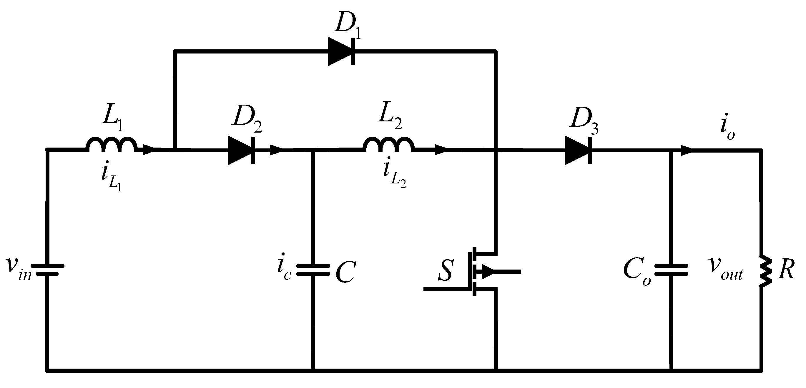
Given the function of the energy mutual aid device, the device should have high power, wide gain, small size, and be lightweight. In this paper, the quadratic boost converter is shown in Figure 2. The converter does not use either a high-frequency converter or an excessive number of switching converters, which greatly reduces the volume and cost of the device. The quadratic boost converter used in the energy mutual aid device can produce higher gain using a smaller duty cycle compared to a conventional boost converter. The average state space model of a quadratic boost converter operating in the continuous current mode is provided as follows:
In the above equation, the average current of inductor is represented by , and the average voltage of capacitor is represented by . and R represent the converter’s input voltage and load resistance.
Figure 2.
Quadratic boost converter.
The equilibrium values of the state variables and control signals obtained according to the above equation are
where , , , , and are the equilibrium values of , , , , and u. indicates the reference of the converter output voltage.
3. Voltage Mode Controller Control Algorithm
3.1. Conventional Voltage Mode Controller
The transformation is based on the Proportional Boost Control (PBC) of a traditional boost converter, with controller gains , , , and all being positive. The equilibrium value of the averaged duty ratio of the quadratic boost converter is derived in Equation (5). To enhance the controlled system’s performance, a proportional integration link is introduced in Equation (6). Despite the controller’s ability to regulate the quadratic converter under varying loads, it exhibits drawbacks during the response process. In practical scenarios, adding integral action is necessary to minimize the steady-state error of the output voltage. However, due to the integral action’s large integrand, fluctuations in the reference voltage and load can lead to increased overshoot and oscillations in the output response. Thus, there exists a tradeoff between the transient and steady-state performance of this controller.
Based on this, an improved voltage mode controller is presented to avoid the problems above.
3.2. Improved Voltage Mode Controller
An improved voltage mode controller for the quadratic boost converter is shown below:
The controller gains , , , , , and h can be adjusted to meet specific requirements. These gains are all positive values. is determined by Equation (9), while remains a predetermined voltage variable. The denominator of Equation (8) is a predetermined positive constant, thus preventing division by zero in Equation (6). The proof of the boundedness of the quadratic function is provided as follows
Equation (9) is represented by the symbol n, that is,
To find the maximum value of n, it is necessary to determine the first-order derivative of n with respect to ()
Set the first-order derivative of n to be equal to zero and obtain two stationary points, i.e., . Then, find the second-order derivative for n
Substituting these two stationary points into the second-order derivative (13) reveals that n has maximum value of h and minimum value of . The magnitude of n is determined by the user-specified value of h. Therefore, through this integration process, even if the output voltage deviates significantly from the reference voltage, the integration result remains within reasonable bounds, enhancing the dynamic response of the output voltage effectively.
3.3. Stability Analysis
Setting (9), (10), and (14)–(17) equal to zero yields the unique equilibrium state of the system
and represent the steady-state values of and .
Approximate stability analysis of voltage-mode control systems is performed using the linearization method. This method is usually used to study the stability of high-order converter systems [23,29]. Now, linearizing (9), (10), and (14)–(17) about (18) obtains a system provided in (19).
where , , , , , , .
For the convenience of the analysis, the value of h is taken as 1. The stability of the system can be determined according to Lyapunov’s first method.
Theorem 1.
The system is stable at equilibrium if all the eigenvalues of coefficient matrix A have negative real parts; that is, the eigen roots of the characteristic equation are all distributed in the left half-plane of the complex plane. If the eigenvalues are of A, at least one of which has a positive real part, the system is unstable at equilibrium.
According to the requirements of the vehicle–vehicle energy mutual aid device, the hardware parameters of the system are provided as follows
Substitute (19) into (20) to obtain the characteristic equation, and then set the gain of the system as follows
Considering the usage in practical situations in the device, the voltage that can be supplied and the required charging voltage are different for electric vehicles.
In the first case, the input voltage 90 V, the output voltage is changed from 200 V to 250 V, and the eigenvalues of the system are shown in Figure 3a. In the second case, the output voltage 250 V and the input voltage changes from 90 V to 150 V. The eigenvalue distribution is shown in Figure 3b. The output power is stabilized at 3 kW. All the eigenvalues shown in the figure are distributed in the left half-plane of the system; i.e., all the eigenvalues of coefficient matrix A have negative real parts, and the system is stable at the equilibrium state.
4. Simulation Verification
The simulation in this paper is based on Matlab/Simulink 2018b, and the quadratic boost converter and its controller are constructed as shown in Figure 4 to verify the effectiveness of the system.
The output voltage of the ESV is used as the input voltage of the energy mutual aid device, and the charging voltage of the ECV is expressed as the output voltage of the energy mutual aid device. In this section, three cases are set up to verify the effectiveness of the quadratic boost converter with a modified voltage-mode controller. If the output response can reach the set value quickly, the overshoot % does not exceed 10% of the set value, and, in the worst case, when is disturbed, the device can still regulate quickly to a stable value. It proves to be functional. The gain and circuit parameters of the selected controller are the same as in (20) and (21). The first and second of the three sets of experiments set up in this paper are to select an electric vehicle as ESV to charge two other ECVs, respectively. The third case is to select an electric vehicle as ECV and charge it with the other two ESVs. The power of charging 3 kW.
- Case 1:In the first case, the Chery QQ ice-cream is taken as ESV and the BaoJun e100 and Hongguang MINIEV are taken as ECVs. According to the parameters in Table 1, the input voltage of the vehicle–vehicle energy mutual aid device is 90V, i.e., 90 V, and the output voltage is 200 V/250 V. The reference voltage 200 V/250 V.As and show in Figure 5, when the Chery QQ ice-cream charges the BaoJun e100, the output voltage steady-state value 200 V, the maximum overshoot 6.8% (less than 10%), and the regulation time 0.14s. When the simulation proceeds to 2 s when a 20% perturbation occurs in , can still recover 200 V output voltage quickly, and the system has strong robustness. The output voltage 3 kW.As and show in Figure 5, when the Chery QQ ice-cream charges the Hongguang MINIEV, 250 V, maximum overshoot 9.6% (less than 10%), and regulation time 0.23 s. When the simulation proceeds to 2 s when a 20% perturbation occurs in , can still recover the 250 V output voltage quickly, and the system has strong robustness. The output voltage 3 kW.In summary, the Chery QQ ice-cream charges the BaoJun e100, Hongguang MINIEV, and the output response can reach the set value quickly, with the overshoot not exceeding 10% of the set value. When was disturbed, the output voltage of ESV was reduced to 80% of the original voltage, the device was able to regulate quickly to the stable value, and the device was effective.
- Case 2:In this case, the BaoJun e100(A) is taken as ESV and BaoJun e100(B) and the Hongguang MINIEV are taken as ECVs. According to the parameters in Table 1, the input voltage of the vehicle–vehicle energy mutual aid device is 110V, i.e., 110 V, and the output voltage is 200 V/250 V. The reference voltage 200 V/250 V.As and show in Figure 6, when the BaoJun e100(A) charges the BaoJun e100(B), 200 V, the maximum overshoot % = 5.3% (less than 10%), and the regulation time 0.15 s. When the simulation proceeds to 2 s, can recover quickly to 200 V when a 20% perturbation occurs in . The system has strong robustness. The output voltage is still stable at 3 kW.As and show in Figure 6, when the BaoJun e100(A) is charged for the Hongguang MINIEV, 250 V, maximum overshoot 9.2% (less than 10%), and regulation time 0.22 s. When the simulation proceeds to 2s, can recover to 250 V quickly when a 20% perturbation of occurs. The system has strong robustness. The output voltage 3 kW.So, by the same argument, the simulation of choosing the BaoJun e100(A) for the BaoJun e100(B) and the Hongguang MINIEV charging can prove the effectiveness of the device.
- Case 3:In contrast to the two cases above, in this case, the Hongguang MINIEV and the Baojun e200(A) are taken as ESVs and the Hongguang MINIEV and the Baojun e200(A) are taken as ECVs. According to the parameters in Table 1, the input voltage of the vehicle–vehicle energy mutual aid device is 96 V/122 V, i.e., 96 V/122 V, and the output voltage is 220 V. The reference voltage 220 V.As shown in Figure 7, the Hongguang MINIEV powers the Baojun e200(A) (), and the Baojun e200(B) powers the Baojun e200(C) (), corresponding to an overshoot % of 6.8%/6.4% and regulation time 0.17 s/0.16 s, respectively. When the simulation proceeds to 2 s, the output voltage and current can quickly recover to the set value when a 20% disturbance of occurs.This case selects the Hongguang MINIEV and the Baojun e200(A) charging for the Baojun e200(B) for simulation to prove the effectiveness of the device.
5. Experimental Verification
In order to verify the effectiveness of the quadratic boost converter controlled through a modified voltage-mode controller for energy mutual aid devices between electric vehicles, the controller hardware-in-the-loop (HIL) experiment is conducted in a real-time simulation system. The detailed topology of the HIL experiment is shown in Figure 8. The emulator consists of a CPU and FPGA. Through the host computer, the control algorithm from the controller is downloaded to the CPU in the simulator to generate control signals; the circuit model is loaded into the FPGA inside the simulator. The FPGA contains the system model of the power electronic components, which enables the real-time simulation of the circuit model. At the same time, the FPGA can internally generate PWM signals. In the simulator, the CPU and FPGA are connected through a bus to realize the self-closed loop simulation. In this case, the control frequency is 5 kHz.
- Experiment 1:Experiment 1 is based on case 1 in the simulation. ESV is selected from the Chery QQ ice-cream, and ECVs are selected from the BaoJun e100, the Hongguang MINIEV, and the experimental results are shown in Figure 9. When the Chery QQ ice-cream is charged for the BaoJun e100, the input voltage of the vehicle–vehicle energy mutual aid device is 90V, i.e., 90 V, and the output voltage of the device 200 V. When the Chery QQ ice-cream is charged for Hongguang MINIE, the input voltage of the vehicle–vehicle energy mutual aid device is 90 V, i.e., 90 V, and the output voltage of the device 250 V. From the experimental results, the energy mutual aid device can quickly generate the voltage needed for ECVs, the overshoot generated is less than 10%, and the stability can be quickly restored when receives a disturbance. It proves the effectiveness of the device.
- Experiment 2:Experiment 2 is based on case 2. The experimental results are shown in Figure 10. BaoJun e100(A) is selected as ESV, and BaoJun e100(B) and Hongguang MINIEV are selected as ECVs. When BaoJun e100(A) charges BaoJun e100(B), 110 V and 200 V. When BaoJun e100(A) charges Hongguang MINIEV, 110 V and 250 V. From the experimental results, the energy mutual aid device can quickly generate the voltage needed for ECV, and the overshoot is less than 10%. 2 s; when receives a disturbance, the device quickly restores stability. The experimental results prove the effectiveness of the device.
- Experiment 3:Experiment 3 is based on case 3. The experimental results are shown in Figure 11. Hongguang MINIEV and Baojun e200(A) are selected as ESVs, and BaoJun e200(B) is selected as ECV. The output voltage of Hongguang MINIEV and Baojun e200(A) is 96 V/22 V, respectively, and BaoJun e200(B) requires a charging voltage of 220 V. From the experimental results, the energy mutual aid device can quickly generate the voltage needed for ECV, the amount of overshoot generated is less than 10%, and the device quickly returns to stability when receives a perturbation at 2 s. The experimental results prove the effectiveness of the device.
6. Conclusions
In order to eliminate consumers’ concerns about purchasing electric vehicles and to promote the development of the electric vehicle industry, this paper has designed an energy mutual aid device that has used a quadratic boost converter controlled by an improved voltage mode controller and has realized the fast replenishment of electric vehicle power battery energy. Compared with the existing literature and devices, the main advantages are as follows.
- Compared with the hardware topology used in [26,30], the quadratic boost converter is used in this paper. The quadratic boost converter uses fewer electrical components to produce both higher and wider voltage gain and higher output power and can greatly reduce the number of electric components. The size and weight of the device can be greatly reduced. It also reduces the cost of the device.
- Compared with the troditional control algorithm, the modified voltage-mode controller is simpler, and it requires only one feedback amount to achieve the desired output. Meanwhile, the modified voltage-mode controller uses integral action based on the normalized voltage error in (17). This makes the integrand bounded. Therefore, due to this integration process, even if the output voltage deviates from the reference voltage by a large amount, it does not make the integration result too large. This can effectively improve the dynamic response of the output voltage.
- Compared to the existing charging devices, the vehicle–vehicle energy mutual aid device is less costly and does not require the modification of the electric vehicle. The device is smaller in size and weight, making it easy to carry around and use. With these effects, the vehicle–vehicle energy mutual aid device can alleviate the battery charging and range problems. Finally, the simulation and experimental results demonstrate the accuracy and feasibility of the conversion device.
Author Contributions
Software, W.W.; Investigation, B.G.; Data curation, Z.Z.; Writing—original draft, S.Z.; Writing—review & editing, J.X. Visualization, W.J. All authors have read and agreed to the published version of the manuscript.
Funding
This research received no external funding.
Data Availability Statement
Data are contained within the article.
Conflicts of Interest
The authors declare no conflict of interest.
References
- Medvedkina, Y.; Khodochenko, A. Renewable Energy and Their Impact on Environmental Pollution in the Context of Globalization. In Proceedings of the 2020 International Multi-Conference on Industrial Engineering and Modern Technologies (FarEastCon), Vladivostok, Russia, 6–9 October 2020; IEEE: Piscataway, NJ, USA, 2020; pp. 1–4. [Google Scholar]
- Evode, R. Modeling of Electric Grid Behaviors having Electric Vehicle charging stations with G2V and V2G Possibilities. In Proceedings of the 2021 International Conference on Electrical, Computer, Communications and Mechatronics Engineering (ICECCME), Mauritius, 7–8 October 2021; IEEE: Piscataway, NJ, USA, 2021; pp. 1–5. [Google Scholar]
- Jia, Y.; Jibrin, R.; Görges, D. Energy-optimal adaptive cruise control for electric vehicles based on linear and nonlinear model predictive control. IEEE Trans. Veh. Technol. 2020, 69, 14173–14187. [Google Scholar] [CrossRef]
- Wang, J.; Cai, Y.; Chen, L.; Shi, D.; Wang, S.; Zhu, Z. Research on compound coordinated control for a power-split hybrid electric vehicle based on compensation of non-ideal communication network. IEEE Trans. Veh. Technol. 2020, 69, 14818–14833. [Google Scholar] [CrossRef]
- Wang, X.; Shahidehpour, M.; Jiang, C.; Li, Z. Coordinated planning strategy for electric vehicle charging stations and coupled traffic-electric networks. IEEE Trans. Power Syst. 2018, 34, 268–279. [Google Scholar] [CrossRef]
- Zhai, C.; Luo, F.; Liu, Y. A novel predictive energy management strategy for electric vehicles based on velocity prediction. IEEE Trans. Veh. Technol. 2020, 69, 12559–12569. [Google Scholar] [CrossRef]
- Wang, R.; Sun, Q.; Sun, C.; Zhang, H.; Gui, Y.; Wang, P. Vehicle-vehicle energy interaction converter of electric vehicles: A disturbance observer based sliding mode control algorithm. IEEE Trans. Veh. Technol. 2021, 70, 9910–9921. [Google Scholar] [CrossRef]
- Jiang, W.; Zhang, X.; Guo, F.; Chen, J.; Wang, P.; Koh, L.H. Large-signal stability of interleave boost converter system with constant power load using sliding-mode control. IEEE Trans. Ind. Electron. 2019, 67, 9450–9459. [Google Scholar] [CrossRef]
- Jiang, W.; Chincholkar, S.H.; Chan, C.Y. Investigation of a voltage-mode controller for a dc-dc multilevel boost converter. IEEE Trans. Circuits Syst. II Express Briefs 2017, 65, 908–912. [Google Scholar] [CrossRef]
- Rui, W.; Qiuye, S.; Pinjia, Z.; Yonghao, G.; Dehao, Q.; Peng, W. Reduced-order transfer function model of the droop-controlled inverter via Jordan continued-fraction expansion. IEEE Trans. Energy Convers. 2020, 35, 1585–1595. [Google Scholar] [CrossRef]
- Kumar, N.; Mohamadi, M.; Mazumder, S.K. Passive damping optimization of the integrated-magnetics-based differential-mode ćuk rectifier. IEEE Trans. Power Electron. 2020, 35, 10008–10012. [Google Scholar] [CrossRef]
- Lotfi Nejad, M.; Poorali, B.; Adib, E.; Motie Birjandi, A.A. New cascade boost converter with reduced losses. IET Power Electron. 2016, 9, 1213–1219. [Google Scholar] [CrossRef]
- Maksimovic, D.; Cuk, S. Switching converters with wide DC conversion range. IEEE Trans. Power Electron. 1991, 6, 151–157. [Google Scholar] [CrossRef]
- Rosas-Caro, J.C.; Ramirez, J.M.; Peng, F.Z.; Valderrabano, A. A DC–DC multilevel boost converter. IET Power Electron. 2010, 3, 129–137. [Google Scholar] [CrossRef]
- Luo, F.L.; Ye, H. Super-lift boost converters. IET Power Electron. 2014, 7, 1655–1664. [Google Scholar] [CrossRef]
- Lin, B.R.; Chen, J.J. Analysis and implementation of a soft switching converter with high-voltage conversion ratio. IET Power Electron. 2008, 1, 386–394. [Google Scholar] [CrossRef]
- Yun, J.J.; Choe, H.J.; Hwang, Y.H.; Park, Y.K.; Kang, B. Improvement of power-conversion efficiency of a DC/DC boost converter using a passive snubber circuit. IEEE Trans. Ind. Electron. 2011, 59, 1808–1814. [Google Scholar] [CrossRef]
- Chan, C.Y.; Chincholkar, S.H.; Jiang, W. Adaptive current-mode control of a high step-up DC/DC converter. IEEE Trans. Power Electron. 2016, 32, 7297–7305. [Google Scholar] [CrossRef]
- Chincholkar, S.H.; Chan, C.Y. Design of fixed-frequency pulsewidth-modulation-based sliding-mode controllers for the quadratic boost converter. IEEE Trans. Circuits Syst. II Express Briefs 2016, 64, 51–55. [Google Scholar] [CrossRef]
- Tan, S.C.; Lai, Y.M.; Tse, C.K. A unified approach to the design of PWM-based sliding-mode voltage controllers for basic DC-DC converters in continuous conduction mode. IEEE Trans. Circuits Syst. I Regul. Pap. 2006, 53, 1816–1827. [Google Scholar]
- Chincholkar, S.H.; Jiang, W.; Chan, C.Y. An improved PWM-based sliding-mode controller for a DC–DC cascade boost converter. IEEE Trans. Circuits Syst. II Express Briefs 2017, 65, 1639–1643. [Google Scholar] [CrossRef]
- Lopez-Santos, O.; Martinez-Salamero, L.; Garcia, G.; Valderrama-Blavi, H.; Sierra-Polanco, T. Robust sliding-mode control design for a voltage regulated quadratic boost converter. IEEE Trans. Power Electron. 2014, 30, 2313–2327. [Google Scholar] [CrossRef]
- Chan, C.Y. Investigation of voltage-mode controller for cascade boost converter. IET Power Electron. 2014, 7, 2060–2068. [Google Scholar] [CrossRef]
- Jiang, W.; Chincholkar, S.H.; Chan, C.Y. Improved output feedback controller design for the super-lift re-lift Luo converter. IET Power Electron. 2017, 10, 1147–1155. [Google Scholar] [CrossRef]
- Li, Y.; Li, K.; Xie, Y.; Liu, J.; Fu, C.; Liu, B. Optimized charging of lithium-ion battery for electric vehicles: Adaptive multistage constant current–constant voltage charging strategy. Renew. Energy 2020, 146, 2688–2699. [Google Scholar] [CrossRef]
- Wang, R.; Li, J.; Sun, Q.; Zhang, H.; Wei, Z.; Wang, P. Energy Transfer Converter Between Electric Vehicles: DC-DC Converter Based on Virtual Power Model Predictive Control. IEEE Trans. Consum. Electron. 2023, 69, 556–567. [Google Scholar] [CrossRef]
- Wang, R.; Sun, Q.; Qin, D.; Li, Y.; Li, X.; Wang, P. Steady-state Stability Assessment of AC-busbar Plug-in Electric Vehicle Charging Station with Photovoltaic. J. Mod. Power Syst. Clean Energy 2020, 8, 884–894. [Google Scholar] [CrossRef]
- López-Santos, O.; Martínez-Salamero, L.; García, G.; Valderrama-Blavi, H.; Mercuri, D.O. Efficiency analysis of a sliding-mode controlled quadratic boost converter. IET Power Electron. 2013, 6, 364–373. [Google Scholar] [CrossRef]
- Rui, W.; Qiuye, S.; Dazhong, M.; Dehao, Q.; Yonghao, G.; Peng, W. Line inductance stability operation domain assessment for weak grids with multiple constant power loads. IEEE Trans. Energy Convers. 2020, 36, 1045–1055. [Google Scholar] [CrossRef]
- Wang, R.; Liu, H.; Li, M.J.; Sun, Q.; Li, X.; Wang, P. Fast charging control method for electric vehicle-to-vehicle energy interaction devices. IEEE Trans. Transp. Electrif. 2022, 9, 4941–4950. [Google Scholar] [CrossRef]
Figure 1.
Portable energy mutual aid device for electric vehicles.

Figure 3.
Root−locus plot of the conventer. (a) The input voltage 90 V, the output voltage is changed from 200 V to 250 V. (b) The output voltage 250 V and the input voltage changes from 90 V to 150 V.
Figure 3.
Root−locus plot of the conventer. (a) The input voltage 90 V, the output voltage is changed from 200 V to 250 V. (b) The output voltage 250 V and the input voltage changes from 90 V to 150 V.
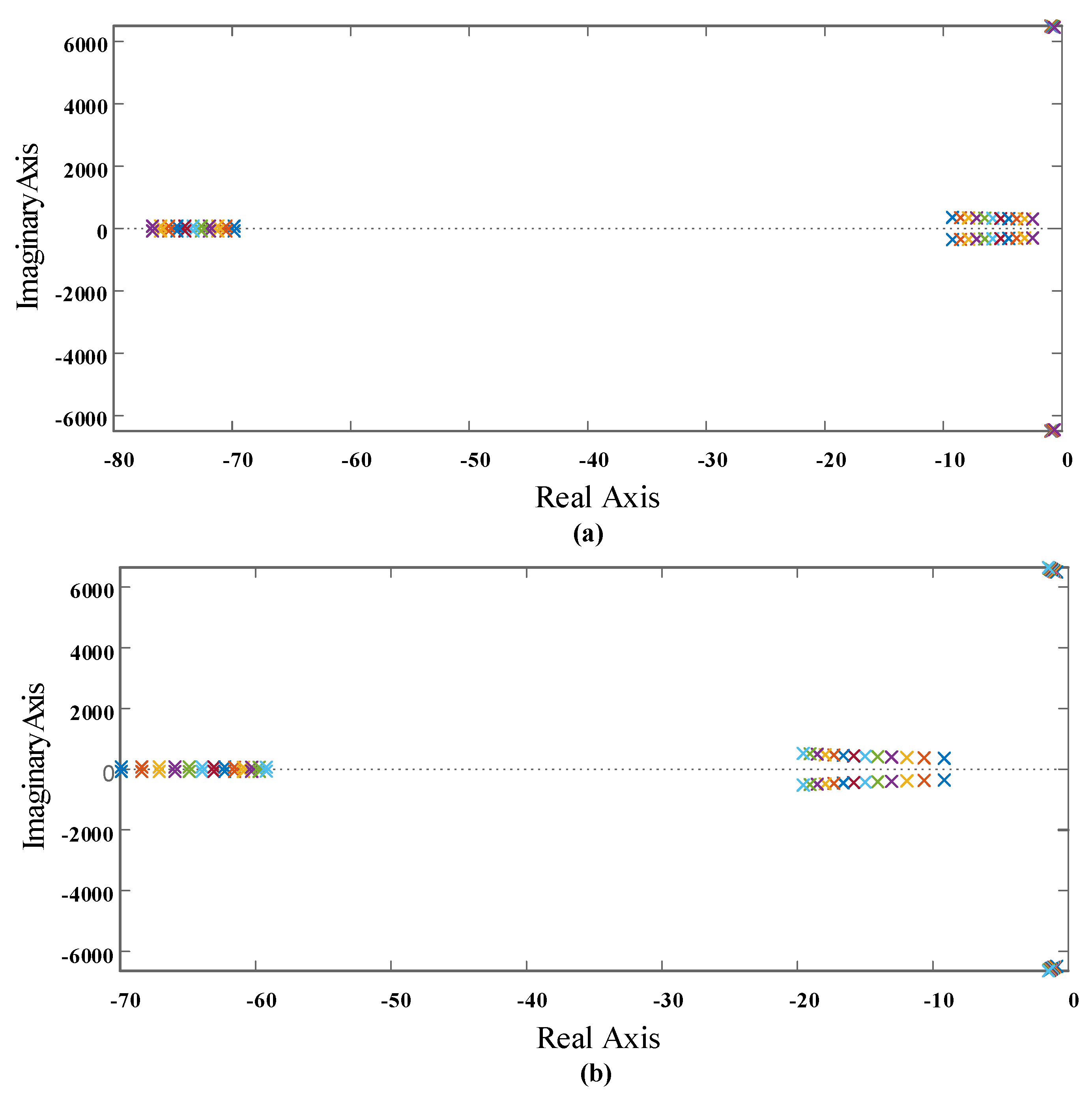
Figure 4.
Block diagram of the closed−loop quadratic boost DC/DC converter system.
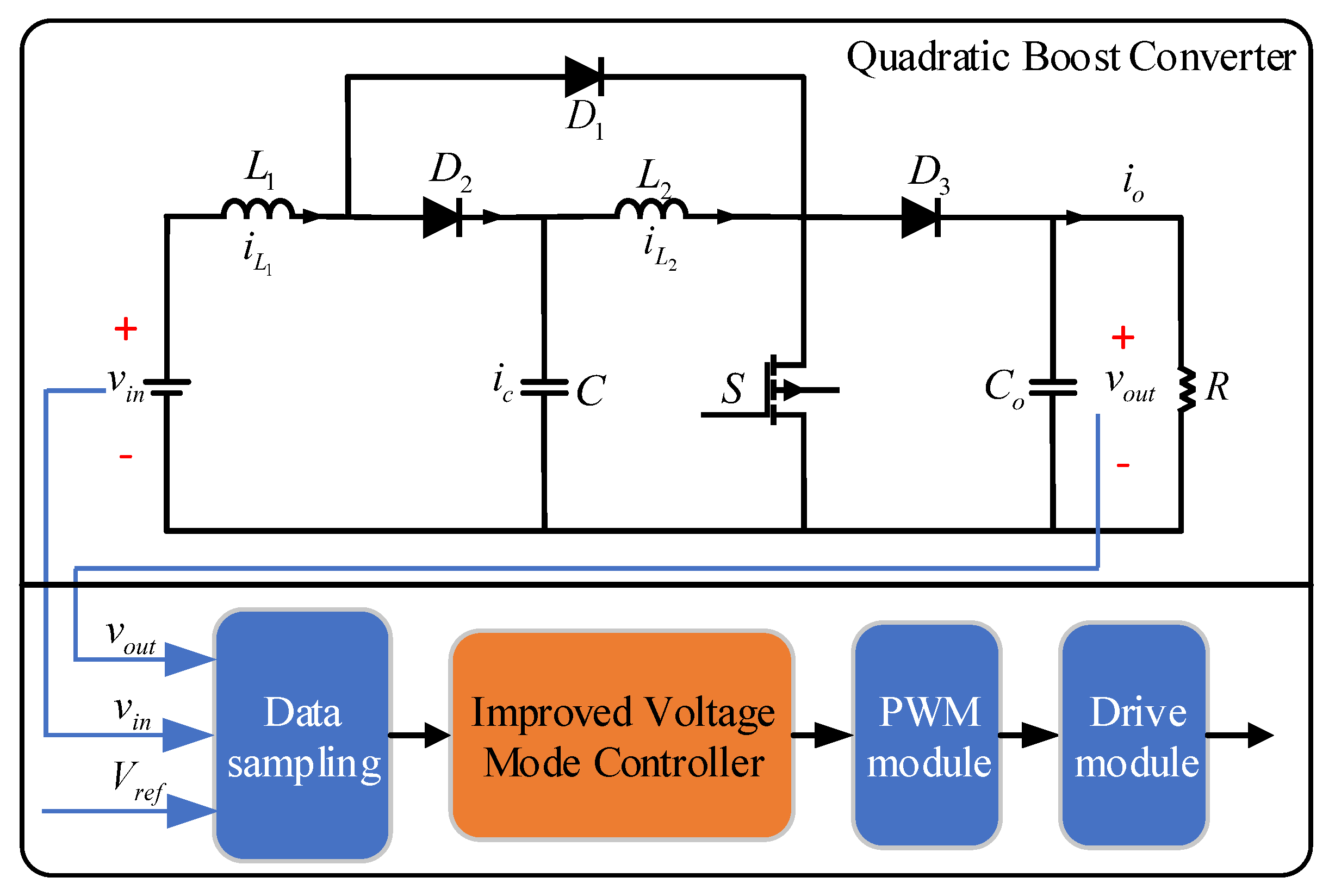
Figure 5.
The voltage and current of the device in case 1.

Figure 6.
The voltage and current of the device in case 2.

Figure 7.
The voltage and current of the device in case 3.

Figure 8.
The HIL experiment topology.
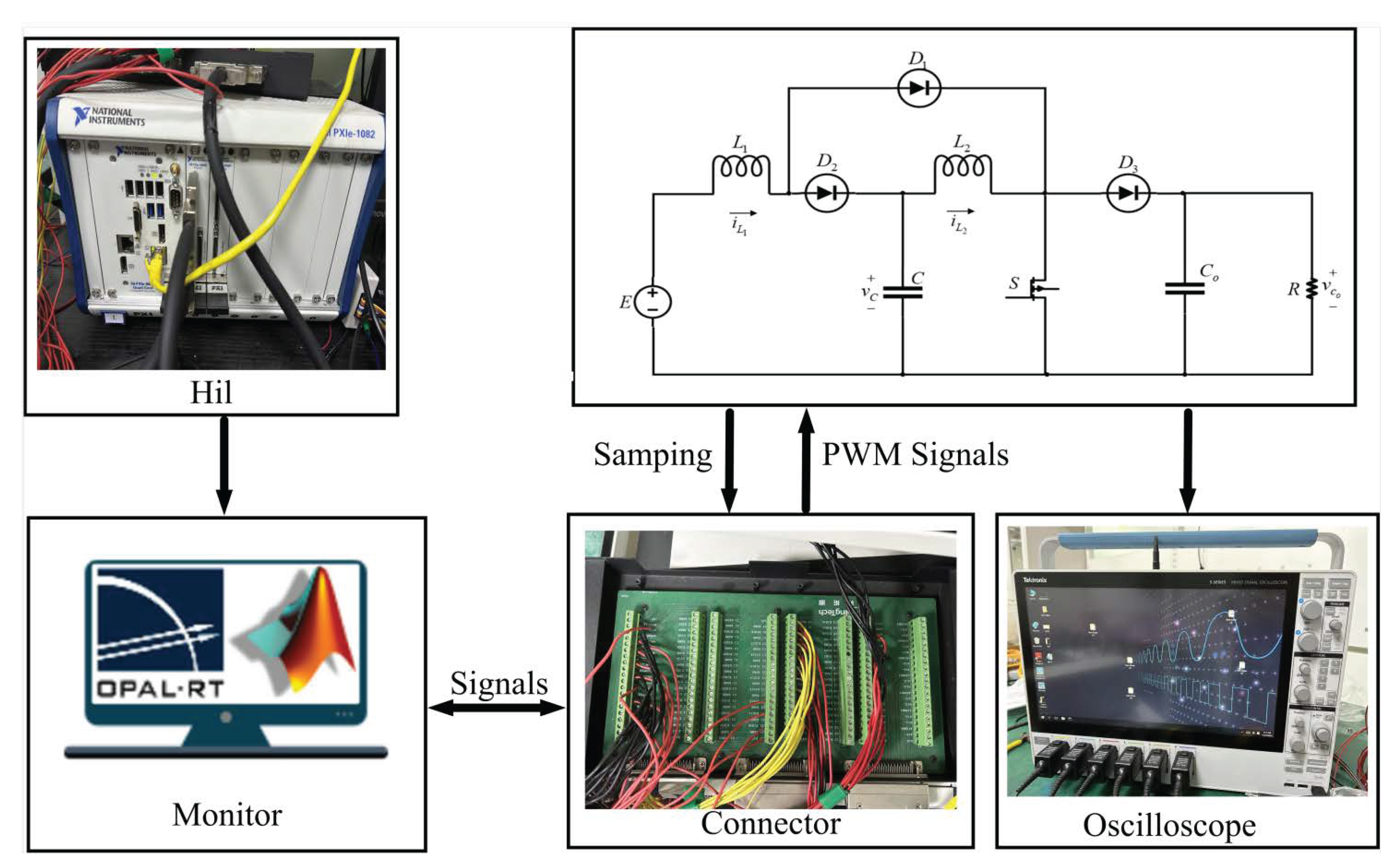
Figure 9.
The actual output voltage and current of the energy interaction converter under HIL experiment in case 1.
Figure 9.
The actual output voltage and current of the energy interaction converter under HIL experiment in case 1.

Figure 10.
The actual output voltage and current of the energy interaction converter under HIL experiment in case 2.
Figure 10.
The actual output voltage and current of the energy interaction converter under HIL experiment in case 2.
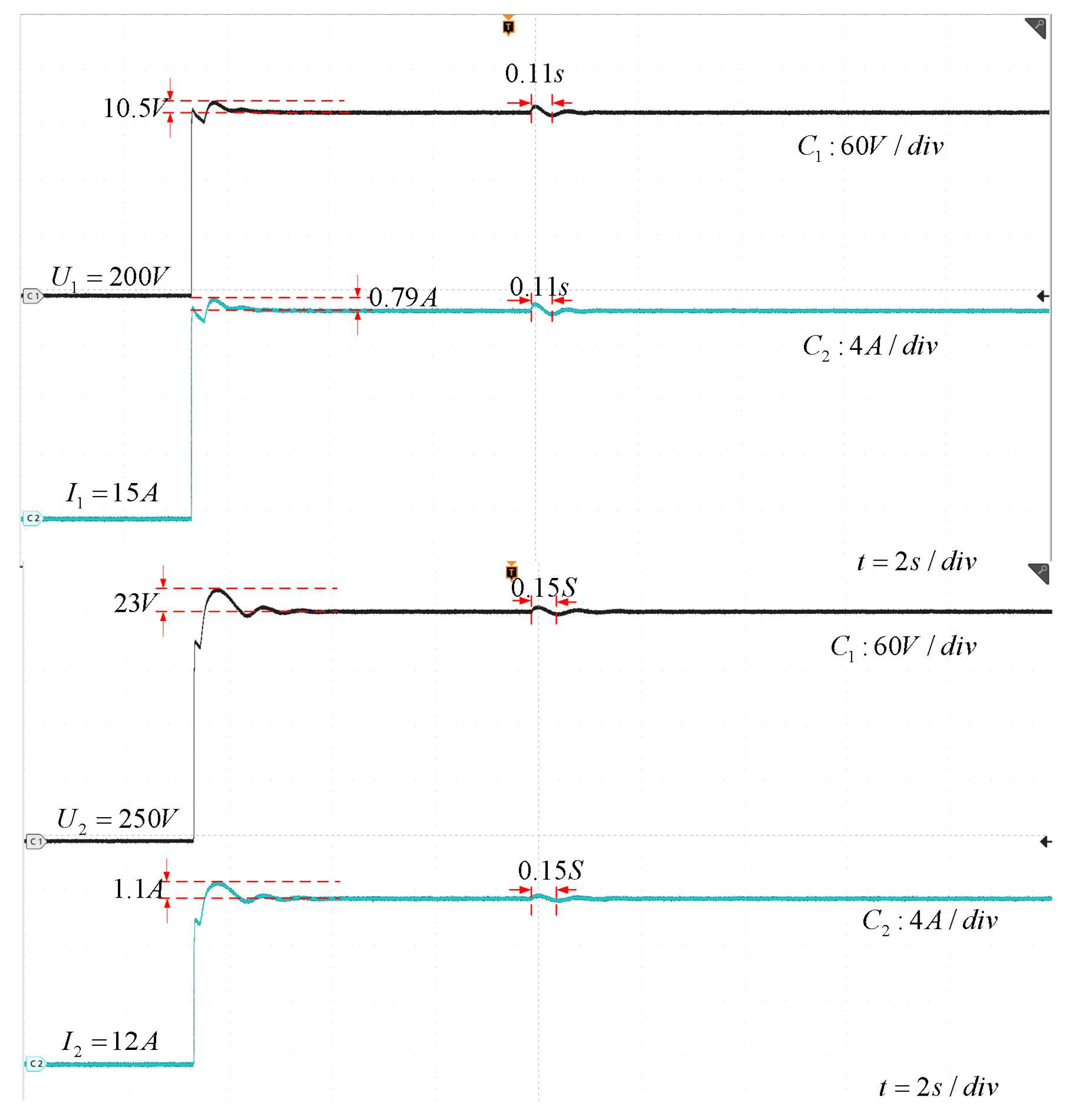
Figure 11.
The actual output voltage and current of the energy interaction converter under HIL experiment in case 3.
Figure 11.
The actual output voltage and current of the energy interaction converter under HIL experiment in case 3.


Table 1.
Different brands of electric vehicles’ power battery performance indicators.
| Different Electric Vehicle Brands | Charging Voltage/V | Output Voltage/V |
|---|---|---|
| Hongguang MINIEV | 250 V or More | 96 V or Less |
| BAOJUN e100 | 200 V or More | 110 V or Less |
| BAOJUN e200 | 220 V or More | 122 V or Less |
| CHERY QQ ice-creame | 250 V or More | 90 V or Less |
| BAOJUN e200 | 220 V or More | 125 V or Less |
Disclaimer/Publisher’s Note: The statements, opinions and data contained in all publications are solely those of the individual author(s) and contributor(s) and not of MDPI and/or the editor(s). MDPI and/or the editor(s) disclaim responsibility for any injury to people or property resulting from any ideas, methods, instructions or products referred to in the content. |
© 2024 by the authors. Licensee MDPI, Basel, Switzerland. This article is an open access article distributed under the terms and conditions of the Creative Commons Attribution (CC BY) license (https://creativecommons.org/licenses/by/4.0/).
Share and Cite
MDPI and ACS Style
Xiao, J.; Zhai, S.; Jia, W.; Wang, W.; Zhang, Z.; Guo, B. Energy Mutual Aid Device of Electric Vehicles: Quadratic Boost Converter with Modified Voltage-Mode Controller. Mathematics 2024, 12, 1531. https://doi.org/10.3390/math12101531
AMA Style
Xiao J, Zhai S, Jia W, Wang W, Zhang Z, Guo B. Energy Mutual Aid Device of Electric Vehicles: Quadratic Boost Converter with Modified Voltage-Mode Controller. Mathematics. 2024; 12(10):1531. https://doi.org/10.3390/math12101531
Chicago/Turabian StyleXiao, Jun, Shuo Zhai, Wei Jia, Weisheng Wang, Zhiyuan Zhang, and Baining Guo. 2024. "Energy Mutual Aid Device of Electric Vehicles: Quadratic Boost Converter with Modified Voltage-Mode Controller" Mathematics 12, no. 10: 1531. https://doi.org/10.3390/math12101531
Note that from the first issue of 2016, this journal uses article numbers instead of page numbers. See further details here.