
Evaluating a Controlled Electromagnetic Launcher for Safe Remote Drug Delivery

1
Wexner Medical Center, The Ohio State University, Columbus, OH 43210, USA
2
Electrical and Computer Engineering, The Ohio State University, Columbus, OH 43210, USA
*
Author to whom correspondence should be addressed.
Technologies 2024, 12(5), 69; https://doi.org/10.3390/technologies12050069
Submission received: 16 April 2024
/
Revised: 8 May 2024
/
Accepted: 13 May 2024
/
Published: 17 May 2024
(This article belongs to the Section Manufacturing Technology)
Abstract
:Biologists and veterinarians rely on dart projectors to inject animals with drugs, take biopsies from specimens, or inject tracking chips. Firearms, air guns, and other launchers are limited in their ability to precisely control the kinetic energy of a projectile, which can injure the animal if too high. In order to improve the safety of remote drug delivery, a lidar-modulated electromagnetic launcher and a soft drug delivery dart were prototyped. A single-stage revolver coilgun and soft dart were designed and tested at distances up to 8 m. With a coil efficiency of 2.25%, the launcher could consistently deliver a projectile at a controlled kinetic energy of 1.00 ± 0.006 J and an uncontrolled kinetic energy of 2.66 ± 0.076 J. Although modifications to charging time, sensors, and electronics could improve performance, our launcher performed at the required level at the necessary distances. The precision achieved with commercial components enables many other applications, from law enforcement to manufacturing.
1. Introduction
1.1. Overview
Controlling the kinetic energy of a projectile at a desired distance has long been key in many scientific, industrial, medical, and other applications [1]. Scientific applications include the distance biopsy of animals and the implantation of tracking chips [2]. Industrial applications include modulating the velocity and thickness of ferrofluid dispositions in additive manufacturing, ensuring proper function of presses and solenoids, and precise control of other automated components [3]. Medical veterinary or biological research applications include ensuring proper injection of sedatives and other drugs into animals from a safe distance [1,4,5]. Although firearms and air guns suffer from intrinsic limitations in ensuring consistent delivery of kinetic energy into projectiles, functional electromagnetic accelerators offer a more consistent solution [3]. To ensure safer remote drug delivery, we used a lidar sensor to modulate the power in a coilgun, thereby enabling consistent delivery of a projectile with 1 Joule (J) of kinetic energy.
1.2. Background
1.2.1. Prior Work Overview
For as long as humans have used projectiles, they have sought ways to ensure more consistent performance of moving objects. From hurled stones to modern conventional munitions, wind, gravity, aerodynamics, and projectile geometry remain the primary considerations when working to achieve predictable, consistent projectile performance. Several complex solutions have been developed to increase consistency and control in projectile performance, such as elaborate guidance systems for missiles and computer-guided “smart bullets”. However, due to their high cost and complexity, it is not feasible to adapt such solutions to other fields where there is a need for lower-cost, managed delivery of kinetic energy at close range (i.e., approximately 10 m or less) [3].
The design presented in this work is expected to have applications primarily in industrial, scientific, and veterinary contexts. In industry, additive manufacturing systems have begun to incorporate ferrofluid deposition [3,6,7], wherein the presence of iron and other magnetic substances in the ferrofluid mixture means that a functional electromagnetic accelerator—such as a coilgun or railgun—can be used instead of a standard nozzle and thermo-mechanical extruder. Through lidar, our design facilitates a more accurate estimation of the distance between the extruder and printing tray, thereby enabling finer control of the material dispersion and layering process [3].
Scientific and veterinary applications include delivering darts or other projectiles at a specific velocity. Impact research tests materials by accelerating projectiles to a desired velocity to simulate collisions. Biologists and veterinarians rely on dart projectors to inject animals with drugs, take biopsies from specimens, or inject tracking chips [1,8,9]. Due to the potential danger posed by animals that may be wild, confused, or sick, researchers may prefer to keep their distance during such interventions. The injection process itself can also pose a risk to the animal; a projectile with excessive velocity can over-penetrate, potentially injuring or even killing the animal [10]. On the other hand, a projectile with insufficient velocity cannot penetrate to the required depth, if at all [11]. However, dart design affected both initial and terminal ballistics [6].
1.2.2. Microneedle Delivery
The syringe-like shape of existing darts is responsible for many complications [7,9]. If the dart travels too fast, it can injure or kill the target [10]. If the dart is too slow, it will not inject. Changing projectile design may rectify many problems with existing dart projectors. Advances in nanomaterials and additive manufacturing provide solutions to current complications, primarily those concerning projectile materials and transdermal drug delivery [12].
Foam dart blasters have existed for decades, and hobbyists have pushed performance well beyond the manufacturers’ original specifications. Blasters that are entirely designed and/or built by hobbyists transcend even these limits, accelerating foam darts to ~100 m per second in some cases [13]. Despite such velocities, the darts’ rubber head, low weight, and wide diameter have been shown to greatly reduce injuries among children. Prior research suggests that adding rubber tips to conventional tranquilizer darts may similarly reduce animal injuries [14]. In conjunction with foam darts, nanomaterials offer another option for drug delivery [15].
Microneedles have been reliably used for drug delivery. They do not require the volume of a typical syringe because drugs can be directly inserted into water-soluble polymers and hydrogels via 3D printing [16,17,18,19,20,21]. The concentration can be increased to compensate for the lack of volume relative to a conventional syringe dart [22,23,24]. Well-documented tranquilizers and sedatives, such as ketamine, have been successfully delivered by microneedles. As such, conventional tranquilizers may be delivered remotely via microneedles [25].
Microneedles do not puncture the skin in the same way that conventional syringes do. Instead of a single point of contact, there are multiple smaller ones [12]. As a result, there is less damage to the tissue, and shallower penetration allows for the successful delivery of a pharmaceutical payload [26]. In light of these observations, it was conceived that a microneedle patch may be mounted on a foam dart and then launched towards a target; as long as the velocity is sufficient to achieve ~1 mm of microneedle penetration, the drug will be delivered successfully [27]. Even if the dart bounces off afterwards, it will still deliver the drug successfully [28]. In contrast, a conventional syringe dart requires > 2 cm of penetration for successful delivery [29,30]. As an added practical benefit, microneedle-equipped darts with 3D-printed polymer-encapsulated drugs are smaller and lighter—and can be stored longer—than conventional syringe darts. However, there are other considerations beyond the projectile itself; the advantages and disadvantages of the launcher must be considered as well.
1.2.3. Limitations
Air guns and firearms both have innate limitations. Although air guns with adjustable velocities were patented decades ago, they have not seen widespread use [31,32]. Projectile speed in air guns drops off after a certain number of shots as air pressure is lost. Similarly, compressed carbon dioxide is susceptible to changes in temperature [33]. Firearm-based dart launchers, which often use blank cartridges to propel their projectiles, may be more consistent [34]. However, the kinetic energy of the projectile cannot be adjusted without changing the amount of propellant. This is largely impractical in the field for pre-made cartridges or blank charges [34]. An active control system capable of precisely modulating a projectile’s kinetic energy would address each described problem. Thus, a functional electromagnetic accelerator-based launcher possesses unique advantages over air guns or firearms.
2. Materials and Methods
2.1. Overview
As documented in the linked Github repository, the electromagnetic launcher we proposed and tested needed to accommodate a variety of dart types and onboard electronics. Due to thermal ablation from prolonged usage, a single-staged coilgun was used instead of a railgun [35,36]. The launcher integrated a lidar sensor in the muzzle that sent a distance value to a voltage controller. To account for distance, the correct value of the current was sent to the coil. A battery and capacitor bank provided the required system. Due to the variety of dart tips used in field biology and veterinary medicine, a revolver cylinder was used instead of a traditional spring-driven box magazine [1,6]. In summary, a revolver-style single-stage coilgun used a lidar sensor to control dart velocity. The total system consisted of one or more projectiles, a control framework for onboard electronics, and a launcher.
2.2. Launcher Operation
The launcher was designed to be compact enough to be wielded single-handedly. The driving circuits and power supply were modulated by a processor, which is connected to a rangefinder input. A lidar rangefinder (the commercially available Benewake TF Luna (Benewake, Beijing, China) LiDAR module) was used to detect distances up to 8 m, wired as shown in Figure 1.
The characteristics of each projectile type were programmed into the onboard processor, which correspondingly adjusted the launch force needed for each projectile type to consistently deliver 1 J of kinetic energy to the target within the effective range of 8 m, well below the documented thresholds for skin penetration [37].
As shown in Figure 2, the sequence started with a trigger pull. The sensor array used the lidar to estimate the distance between the target and the launcher’s “muzzle”. The onboard processor then retrieved the pre-programmed projectile characteristics, which it used to estimate each projectile’s energy loss as a function of distance. The processor then calculated the corresponding energy required by the electromagnetic coil and sent a signal to the driver for the power supply. This caused the driving circuit and power supply to charge to the appropriate voltage and then activate. The projectile was then launched.
2.3. Projectile Design
The projectile was based on existing recreational foam blaster short darts, with a custom microneedle and 3D-printed drugs epoxied to the rubber tip. The average diameter of the darts was 12.7 mm, and the average length was 72 mm. The darts used were acquired from commercially available foam dart blasters. A ferromagnetic insert (M4 × 12 mm bolt) was pressed into the dart to ensure that the electromagnetic launch system could interact with it. A cross-sectional view of the magnetic dart is depicted in Figure 3.
An added benefit of inserting an M4 bolt behind the tip is that upon impact, the steel dowel exerts more pressure on the microneedle patch, thereby increasing the chance of successful injection. The projectile weighed approximately 0.0114 kg. As determined by early testing, the low mass of the microneedle patch (<1 g) was largely negligible to the center of balance and inertia, so further evaluation was conducted without it. Once the optimal projectile had been designed, the launcher was optimized.
2.4. Launcher Design
The launcher contained the requisite electronics and revolver cylinder; the revolver cylinder was selected for its reliability in the event that a rapid follow-up shot was required, as well as for its ability to accommodate a greater variety of dart types than a conventional box magazine. To reduce any felt recoil and to increase potential accuracy, the launcher was designed to launch darts from the bottom chamber of the cylinder (called the 6 o’clock position). The electronics were placed internally, as shown in Figure 4.
2.5. Launcher Electronics
The onboard electronics were controlled by a Kyber Atmega328p (Bridgold, Liushi, China), a microcontroller comparable to an Arduino Nano, wired as shown in Figure 5.
The capacitor charging circuit is shown in Figure 6. Two 450 V 1000 uF capacitors were used to power the coil, which was made of 215 turns of 18 American Wire Gauge (AWG) enameled copper wire. The highest possible current density was estimated at 51,354,656 [35]. As extensive research exists on coilgun design, the coil’s characteristics were determined by trial and error, iterating from well-established prior experimental work and simulations [35,36]. When activated by the trigger, energy flowed from the two capacitors into the coil.
The wire was wrapped along a 45 mm 3D-printed polylactic acid (PLA) shaft. The launcher was single-staged to reduce complexity and evaluate the viability of the concept.
As shown in Figure 7, power was provided by a 3.7 V lithium polymer (LiPo) battery, stepped up to 12 V with an MT3608 boost converter (Aerosemi Technology, Xi’an, China). A voltage of 5 V was used to run the control circuitry. Ceramic cement resistors were used due to the high current density present in the launcher. Except for the lidar sensor, electronics were fitted into 3D-printed housing.
2.6. Launcher Housing
The launcher casing consisted of ten parts that were 3D-printed in PLA. The infill used varied on the parts. Smaller parts of the housing were printed at 20% infill for speed and material economy. Although the primary launch mechanism was electromagnetic, the cylinder was mechanically cycled with each trigger pull. Due to the double-action revolver design, certain components had to be especially robust and reliable. The most important components, such as the coil base and trigger, were printed at 100% infill for strength. Depending on the requirements for strength, other components were printed between 40 and 80% infill. The launcher was 105 mm in width, 184.5 mm in height, and 210 mm in length. The total weight was approximately 1.6 kg.
As shown in Figure 8, the launcher was fixed for live testing. In order to measure launch velocity, a chronograph was affixed to the barrel.
As shown in Figure 9, the optical chronograph used two infrared LEDSs, each paired with a photoreceiver. Each device pair was a set distance of 5 cm from each other. As with commercial chronographs, the difference in times over a known distance when the projectile passed both was used to calculate the velocity.
2.7. Calculations
The lidar sensor directly adjusted the voltage applied to the primary coil. Kinetic energy E was a function of projectile mass m and velocity v.
As shown in Equation (2), the modulated velocity was a function of the expected drag and projectile drop-off over distance due to gravity. Thus, to overcome drag and drop-off, it was necessary to impart additional kinetic energy to the dart. Due to the short ranges involved, as well as the 8-bit microcontroller memory limitations, energy loss due to drag and drop-off was assumed to be negligible at the relatively close range (~8 m) [38].
Because projectile mass remains constant, the modulated velocity () was increased to compensate for drop-off [35]. Potential energy U in a capacitor is a function of capacitance C and voltage . When combined with Equation (1), the product of the coil efficiency () and potential energy U stored in the capacitors can be set equal to the kinetic energy, as shown in Equation (2).
The voltage necessary to achieve the launch velocity is calculated in Equation (3). While the atmosphere could provide drag, it was assumed to be negligible over the short distance between the chronograph and the coil (<3 cm).
Knowing the mass and velocity of the projectile enables the percent efficiency of the launcher to be calculated. The capacitor parameters establish a fixed upper boundary for shot power; the observed kinetic energy values are a fraction of this boundary.
By solving for efficiency , the specific input energy to the coils can be calculated as shown in Equation (4). The efficiency is a ratio between kinetic and potential energy, able to be broadly applied across other implementations. The efficiency may optimize capacitor charging and energy delivery to the primary coil.
The total potential energy in the capacitor bank was a function of the measured distance. Based on the calculated efficiency , the launcher would discharge as long as the capacitors stored a sufficient or greater energy to reach 1 J at the desired distance. The lidar’s measured distance in centimeters d was encoded as an 8-bit value, rounded to the nearest whole integer, representing the distance in meters. Each distance corresponded to a hard-coded voltage value, . Using 1 J as the desired kinetic energy for Equation (1), the model used to calculate the voltage for the modulated distance is shown in Equation (5).
As shown in Equation (6), the minimum needed voltage for launching the projectile is constrained by the kinetic energy threshold. Without modulation, the projectile would be unbounded, as modeled in Equations (2) and (3). The entire system was modeled in Figure 2.
2.8. Evaluation Criteria
The launcher was tested in two phases: once with lidar modulation and once without lidar modulation. The absence of lidar modulation made it possible to calculate coil efficiency; in turn, those results were used to evaluate lidar-based power modulation with the ultimate goal of ensuring a consistent kinetic energy delivery of 1 J. The calculated potential energy was compared to the measured kinetic energy. An integrated, muzzle-mounted chronograph and video from a smartphone camera were used to measure projectile velocity. The launcher setup is shown in Figure 10.
As shown in Figure 10, the launcher was fixed away from a wooden target at intervals of 1 m, up to a total distance of 8 m. The launch velocity was compared to the impact velocity, and experimental values were contrasted with the initial calculations. The first tests would be conducted with a nearly fully charged capacitor bank of at least 120 J, without modulation. Two trials were conducted at each distance. From this, coil efficiency would be calculated.
Based on this value, a second series of tests was conducted with partially filled capacitor banks of at least 40 J to ensure a consistent kinetic energy. Less energy stored in the capacitor banks would reduce the recharge time, while ensuring sufficient energy was delivered during the modulated trials. The same number of trials was conducted. Finally, modulated and unmodulated velocities would be compared at each distance interval. Given the short distances involved, a linear trend between distance and energy drop-off was hypothesized. All relevant information is documented in the repository [39].
3. Results
The sequence of tests progressed from unmodulated power to calculate coil efficiency , modulated power to ensure consistent energy, and a direct comparison between both modulated and unmodulated power at previously established distances. The first tests used full-power shots. Following the calculation of efficiency , the lidar modulation of the darts was tested.
Capacitor bank energy was not always at maximum, due to safety and efficacy reasons. Based on the observed values shown in Figure 11, the coil efficiency was 2.25%. Without lidar modulation, each shot required an average of 377.1 ± 1.8 V, yielding an average velocity of 21.98 ± 0.11 m/s and an all-trials average kinetic energy of 2.66 ± 0.076 J. The average charge time between full-power shots was 32.0 s. The decreasing linear relationship between distance and power had an value of 0.89. As shown in Figure 12, the capacitors required less power to achieve the desired kinetic energy with lidar modulation.
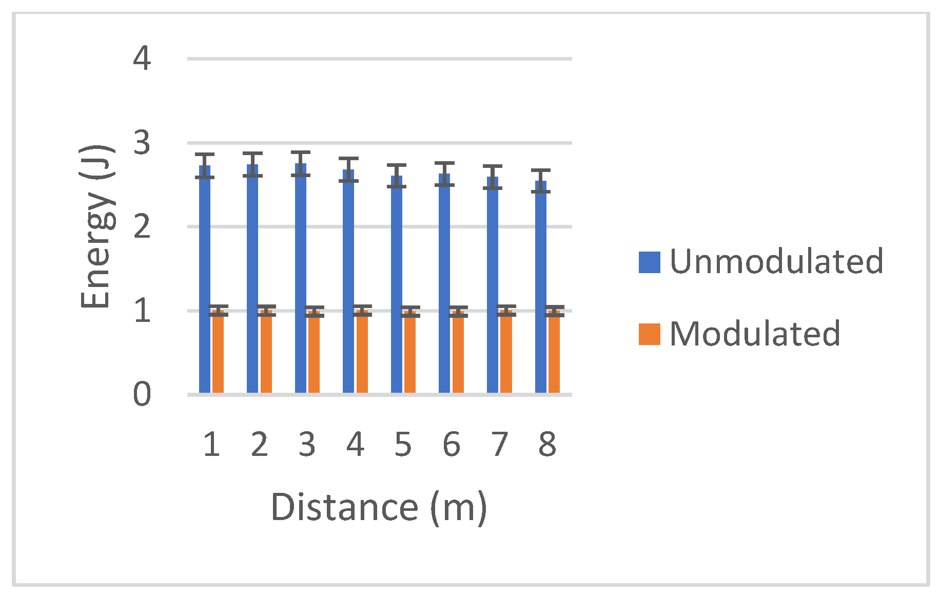
As illustrated in Figure 13, lidar modulation was applied at each previously investigated increment without loss in efficiency. As with the first phase of research, capacitor energy was not fully charged for each test, owing to the calculation of to ensure more than sufficient energy. With modulation, each shot required an average of 229.5 ± 2.2 V, resulting in an average velocity of 13.5 ± 0.13 m/s and average kinetic energy of 1.00 ± 0.006 J. The average charge time between lidar-modulated shots was 8.3 s. With lidar modulation, the capacitors required less power.
With lidar modulation, average full-power kinetic energy was only 37.5% that of average full-power kinetic energy without modulation.
4. Discussion
4.1. Overview
Our velocity-modulated revolver coilgun consistently delivered projectiles at an average kinetic energy of 1.00 ± 0.006 J. Electromagnetic accelerators yield far more consistent projectile velocities than conventional firearms or air guns [35]. Even using commercial components, the launcher was able to achieve high reliability. Furthermore, even at a low coil efficiency of 2.25%, the launcher was still capable of an average unmodulated kinetic energy of 2.66 ± 0.076 J across all trials. Even when the capacitor bank was not fully charged, the launcher reliably achieved 1 J of kinetic energy at each test distance. The lower kinetic energy and soft dart can greatly reduce the potential for unintended injury and offer the potential to adapt to other projectile types [6]. Although originally designed for remote drug delivery, coilguns have many other veterinary and industrial applications [3,8]. Without the need for expensive onboard guidance systems, the launcher leveraged electromagnetic accelerators for remote drug delivery.
4.2. Limitations
The launcher and projectile have several limitations. Because the microcontroller uses 8-bit memory, the onboard processing could not account for more complex drag compensation calculations. Another limitation was the relatively long charge times between shots; although the launcher reliably cycled between multiple chambers, the position and distance of targets could substantially change. Another limiting factor was the lidar resolution, capped at 8 m. Although 8 m was sufficient for our tests, more complex trajectories, aerodynamic drag, and projectile drop-off may be required for targets beyond such close range. Similarly, conventional sights could be added to assist with aiming. However, these changes would be iterative—rather than fundamental—improvements.
4.3. Future Work
The prototype launcher could be applied to other fields and situations. A study with a wider scope could examine drug delivery on live animal subjects or tissue phantoms. Accuracy may be improved by integrating a gyroscope, longer-ranged lidar, and improved microcontroller. A more complex control model would be necessary for drag and projectile drop-off. A multiple-stage coilgun could add more kinetic energy and effective range for the system. While impractical for a conventional weapon, a similar system could be adapted for less-lethal launchers for law enforcement and ferrofluid-based additive manufacturing [3,37]. The coilgun remains an underexplored tool for remote drug delivery that offers more potential than existing technologies.
5. Conclusions
A single-stage revolver coilgun and soft dart were designed and tested at distances up to 8 m. With a coil percent efficiency of 2.25%, the launcher was able to consistently deliver a projectile at a controlled kinetic energy of 1.00 ± 0.006 J and an uncontrolled kinetic energy of 2.66 ± 0.076 J. Although improvements to charging time, sensors, and electronics could improve performance, the launcher performed at the required level at the necessary distances even without such augmentations. The precision achieved with commercial components enables a host of other applications, from law enforcement to 3D printing. Lidar-directed electromechanical actuators have been successfully implemented with low-cost, open-source components, which can be directly implemented in ferrofluid printing and industrial automation [3].
Author Contributions
Conceptualization, J.L. and J.S.; methodology, J.S.; software, J.S.; validation, J.L., J.S. and Q.T.; formal analysis, J.L.; investigation, J.S.; resources, Q.T.; data curation, J.L.; writing—original draft preparation, J.L.; writing—review and editing, J.L.; visualization, J.S.; supervision, J.L. and Q.T.; project administration, J.L.; funding acquisition, Q.T. All authors have read and agreed to the published version of the manuscript.
Funding
This research received no external funding.
Institutional Review Board Statement
Not applicable.
Informed Consent Statement
Not applicable.
Data Availability Statement
The data, models, and supplementary information used in this launcher are available at: https://github.com/javeharron/magnetaralpha (publicly accessible since 1 August 2023).
Acknowledgments
The authors would like to thank The Ohio State University.
Conflicts of Interest
The authors declare no conflicts of interest.
References
- Barrett-Lennard, L.; Smith, T.G.; Ellis, G.M. A cetacean biopsy system using lightweight pneumatic darts, and its effect on the behavior of killer whales. Mar. Mammal Sci. 1996, 12, 14–27. [Google Scholar] [CrossRef]
- Bush, M. Remote drug delivery systems. J. Zoo Wildl. Med. 1992, 1992, 159–180. [Google Scholar]
- Vekselman, V.; Sande, L.; Kornev, K.G. Fully magnetic printing by generation of magnetic droplets on demand with a coilgun. J. Appl. Phys. 2015, 118, 224902. [Google Scholar] [CrossRef]
- Kreeger, T.J. Overview of delivery systems for the administration of contraceptives to wildlife. Contracept. Wildl. Manag. 1997, 1997, 29–48. [Google Scholar]
- Isaza, R. Remote drug delivery. Zoo Anim. Wildl. Immobil. Anesth. 2014, 2014, 155–169. [Google Scholar]
- Cattet, M.R.; Bourque, A.; Elkin, B.T.; Powley, K.D.; Dahlstrom, D.B.; Caulkett, N.A. Evaluation of the potential for injury with remote drug-delivery systems. Wildl. Soc. Bull. 2006, 34, 741–749. [Google Scholar] [CrossRef]
- Hairgrove, T.; Gill, R.; Waters, C.; Miller, R.; Mays, T.; Miller, M.; Fajt, V. Does dart gun delivery of antibiotics cause changes in drug disposition or meat quality? Am. Assoc. Bov. Pract. Conf. Proc. 2016, 2016, 167–168. [Google Scholar] [CrossRef]
- Pagano, A.M.; Peacock, E.; McKinney, M.A. Remote biopsy darting and marking of polar bears. Mar. Mammal Sci. 2014, 30, 169–183. [Google Scholar] [CrossRef]
- Noren, D.P.; Mocklin, J.A. Review of cetacean biopsy techniques: Factors contributing to successful sample collection and physiological and behavioral impacts. Mar. Mammal Sci. 2012, 28, 154–199. [Google Scholar] [CrossRef]
- Bearzi, G. First report of a common dolphin (Delphinus delphis) death following penetration of a biopsy dart. J. Cetacean Res. Manag. 2000, 2, 217–222. [Google Scholar] [CrossRef]
- Tarmizi, M.R.; Zainuddin, Z.Z. Low-cost remote drug delivery blow-dart for veterinary use. J. Wildl. Parks 2020, 35, 39–48. [Google Scholar]
- Economidou, S.; Uddin, M.; Marques, M.; Douroumis, D.; Sow, W.; Li, H.; Reid, A.; Windmill, J.; Podoleanu, A. A novel 3D printed hollow microneedle microelectromechanical system for controlled, personalized transdermal drug delivery. Addit. Manuf. 2021, 38, 101815. [Google Scholar] [CrossRef]
- Philips, B. How Accurate Is a 300fps Nerf Blaster? 30 May 2020. Available online: https://www.youtube.com/watch?v=vZtZMJEb9k4 (accessed on 1 June 2022).
- Gallagher, G.R.; Petzinger, C.; Rieger, J.A.; Dziurzynski, A.D.; Thayer, O. Development of a Safer Tranquilizer Dart. Proc. Vertebr. Pest Conf. 2010, 24, 1. [Google Scholar] [CrossRef]
- Horst, D.J. 3D printing of pharmaceutical drug delivery systems. Arch. Org. Inorg. Chem. Sci. 2018, 1, 1–5. [Google Scholar] [CrossRef]
- Jain, A.; Bansal, K.K.; Tiwari, A.; Rosling, A.; Rosenholm, J.M. Role of polymers in 3D printing technology for drug delivery-an overview. Curr. Pharm. Des. 2018, 24, 4979–4990. [Google Scholar] [CrossRef] [PubMed]
- Lui, Y.S.; Sow, W.T.; Tan, L.P.; Wu, Y.; Lai, Y.; Li, H. 4D Printing and Stimuli-responsive Materials in Biomedical Applications. Acta Biomater. 2019, 92, 19–36. [Google Scholar] [CrossRef]
- Martinez, P.R.; Goyanes, A.; Basit, A.W.; Gaisford, S. Fabrication of Drug-Loaded Hydrogels with Stereolithographic 3D Printing. Int. J. Pharm. 2017, 532, 313–317. [Google Scholar] [CrossRef] [PubMed]
- Devi, L.; Gaba, P.; Chopra, H. Tailormade Drug Delivery System: A Novel Trio Concept of 3DP+ Hydrogel+ SLA. J. Drug Deliv. Ther. 2019, 9, 861–866. [Google Scholar] [CrossRef]
- Trenfield, S.; Awad, A.; Madla, C.; Hatton, G.; Firth, J.; Goyanes, A.; Gaisford, S.; Basit, A. Shaping the future: Recent advances of 3D printing in drug delivery and healthcare. Expert Opin. Drug Deliv. 2019, 16, 1081–1094. [Google Scholar] [CrossRef]
- Massei, G.; Cowan, D. Fertility control to mitigate human–wildlife conflicts: A review. Wildl. Res. 2014, 41, 1–21. [Google Scholar] [CrossRef]
- Allen, L.; Ansel, H.C. Ansel’s Pharmaceutical Dosage Forms and Drug Delivery Systems; Lippincott Williams & Wilkins: Philadelphia, PN, USA, 2013. [Google Scholar]
- Lepowsky, E.; Tasoglu, S. 3D printing for drug manufacturing: A perspective on the future of pharmaceuticals. Int. J. Bioprinting 2018, 4, 1. [Google Scholar] [CrossRef]
- Xing, J.F.; Zheng, M.L.; Duan, X.M. Two-photon polymerization microfabrication of hydrogels: An advanced 3D printing technology for tissue engineering and drug delivery. Chem. Soc. Rev. 2015, 44, 5031–5039. [Google Scholar] [CrossRef] [PubMed]
- Cho, H.; Jammalamadaka, U.; Tappa, K. Nanogels for pharmaceutical and biomedical applications and their fabrication using 3D printing technologies. Materials 2018, 11, 302. [Google Scholar] [CrossRef]
- Mobaraki, M.; Ghaffari, M.; Yazdanpanah, A.; Luo, Y.; Mills, D.K. Bioinks and bioprinting: A focused review. Bioprinting 2020, 18, e00080. [Google Scholar] [CrossRef]
- Rosenfield, D.A.; Acosta, A.; Tavares, D.T.; Pizzutto, C.S. Potential remote drug delivery failures due to temperature dependent viscosity and drug-loss of aqueous and emulsion-based fluids. J. Threat. Taxa 2021, 13, 17639–17645. [Google Scholar] [CrossRef]
- Walcott, H.E.; Curanovic, T.; Ghani, B.S.E.N. The Development and Testing of a Dual Function Underwater Dart Rifle. 2012. Available online: https://www.researchgate.net/profile/Horace-Walcott/publication/344179992_2012_PROCEEDINGS_AAZV_CONFERENCE_257_THE_DEVELOPMENT_AND_TESTING_OF_A_DUAL_FUNCTION_UNDERWATER_DART_RIFLE/links/5f5993e94585154dbbc3fec0/2012-PROCEEDINGS-AAZV-CONFERENCE-257-THE-DEV (accessed on 1 June 2022).
- Rosenfield, D.; Ferraro, M.; Igayara, C.; Cortopassi, S.R.G.; Pizzutto, C.S. Chemical immobilization of free-living capybaras (Hydrochoerus hydrochaeris) using ketamine-dexmedetomidine combination and a remote drug delivery system. Braz. J. Vet. Med. 2020, 42, e107220. [Google Scholar]
- Wolfe, L.L.; Miller, M.W. Using tailored tranquilizer combinations to reduce stress associated with large ungulate capture and translocation. J. Wildl. Dis. 2016, 52, S118–S124. [Google Scholar] [CrossRef]
- Milliman, K. Pressure-regulated gas gun. U.S. Patent US4616622A, 14 October 1986. Available online: https://patents.google.com/patent/US4616622A/en?oq=US4616622A (accessed on 2 July 2021).
- Bhogal, M. Controlling the Velocity of Projectiles from Gas-Powered Guns. US Patent US5265582A, 30 November 1993. [Google Scholar]
- Pneu-Dart. Available online: https://www.pneudart.com (accessed on 1 May 2019).
- Paxarms. Paxarms New Zealand LTD. Available online: http://www.paxarms.com/ (accessed on 6 May 2019).
- Kim, S.W.; Jung, H.K.; Hahn, S.Y. An optimal design of capacitor-driven coilgun. IEEE Trans. Magn. 1994, 30, 207–211. [Google Scholar]
- Schnurr, N.; Kerrisk, J.; Parker, J. Numerical predictions of railgun performance including the effects of ablation and arc drag. IEEE Trans. Magn. 1986, 22, 1733–1738. [Google Scholar] [CrossRef]
- Koene, B.; Id-Boufker, F.; Papy, A. Kinetic non-lethal weapons. Neth. Annu. Rev. Mil. Stud. 2008, 2008, 9–24. [Google Scholar]
- Alyassi, R.; Khonji, M.; Karapetyan, A.; Chau, S.C.K.; Elbassioni, K.; Tseng, C.M. Autonomous recharging and flight mission planning for battery-operated autonomous drones. IEEE Trans. Autom. Sci. Eng. 2022, 20, 1034–1046. [Google Scholar] [CrossRef]
- LaRocco, J. Magnetar Alpha Repository. Available online: https://github.com/javeharron/magnetaralpha (accessed on 1 August 2023).
Figure 1.
TF Luna LiDar wiring diagram, including power (VCC), ground (GND), and value outputs (SDA and SCL). Port wires 1–3 denote control and output parameters, with ports 4 and 5 connecting to ground.
Figure 1.
TF Luna LiDar wiring diagram, including power (VCC), ground (GND), and value outputs (SDA and SCL). Port wires 1–3 denote control and output parameters, with ports 4 and 5 connecting to ground.
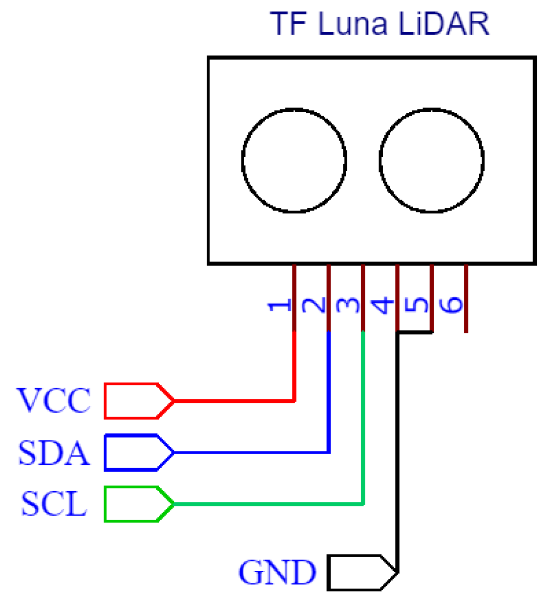
Figure 2.
Discharge process flow chart detailing steps from activating launcher.

Figure 3.
Magnetic dart cross-section, with the steel dowel (M4 bolt) placed behind the rubber tip.
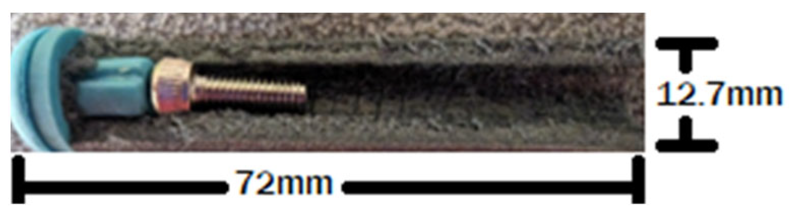
Figure 4.
Labeled diagram of the dart launcher, with the placement of primary components.

Figure 5.
Labeled microcontroller wiring diagram. Wiring outputs in J1 from simulation, and D/A denote official documentation. Design specific outputs denoted in blue.
Figure 5.
Labeled microcontroller wiring diagram. Wiring outputs in J1 from simulation, and D/A denote official documentation. Design specific outputs denoted in blue.

Figure 6.
Capacitor charging circuit and boost converters. Odd numbers (1, 3) denote device voltage inputs and active outputs. Even numbers (2, 4) denote connections to ground (GND).
Figure 6.
Capacitor charging circuit and boost converters. Odd numbers (1, 3) denote device voltage inputs and active outputs. Even numbers (2, 4) denote connections to ground (GND).

Figure 7.
(A) System status LEDs, (B) trigger button, (C) calibration button, and (D) battery wiring. Wiring in D: (1) Voltage (VCC) and (2) Ground.
Figure 7.
(A) System status LEDs, (B) trigger button, (C) calibration button, and (D) battery wiring. Wiring in D: (1) Voltage (VCC) and (2) Ground.
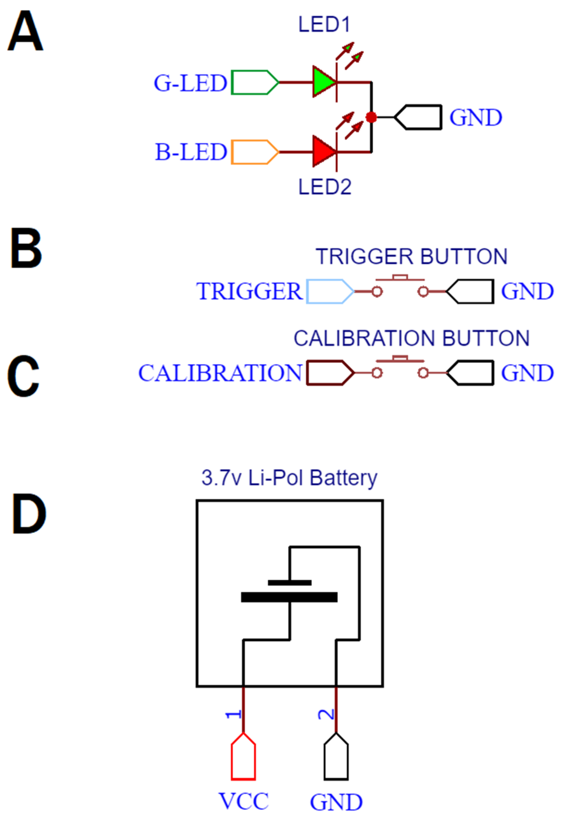
Figure 8.
Partial launcher assembly and integrated chronograph in live testing configuration.

Figure 9.
Optical chronograph wiring diagram.
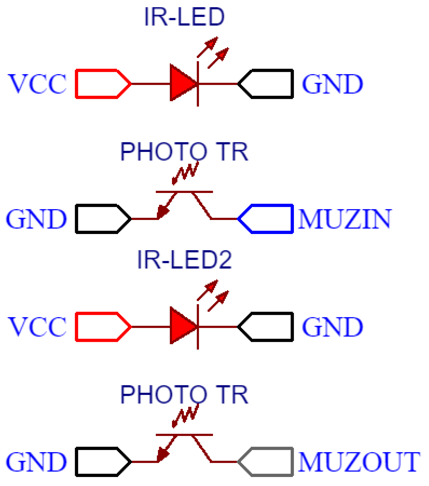
Figure 10.
Launcher testing arrangement.
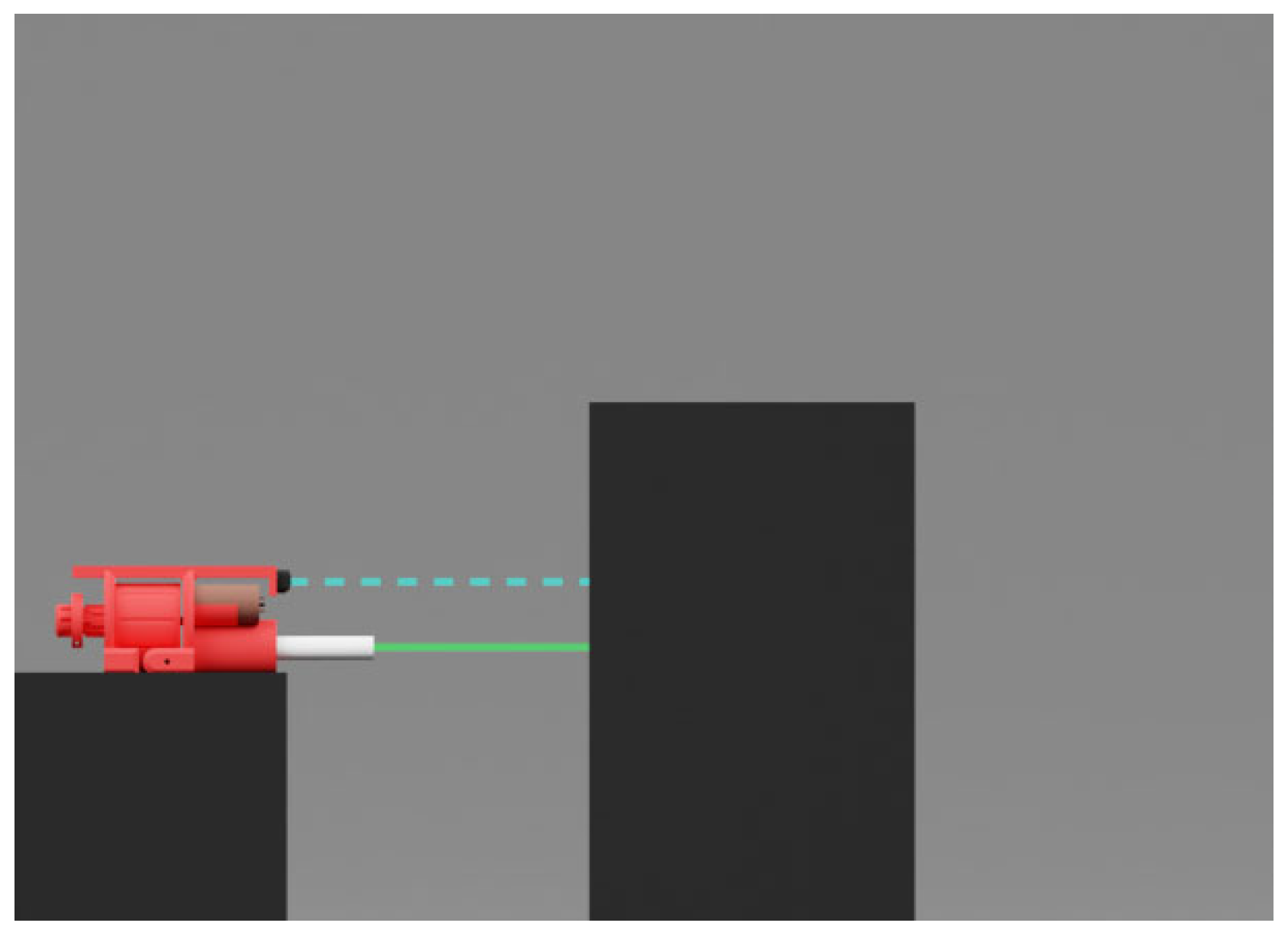
Figure 11.
Comparative measurements of capacitor energy (U) and measured kinetic energy (KE) without lidar modulation.
Figure 11.
Comparative measurements of capacitor energy (U) and measured kinetic energy (KE) without lidar modulation.
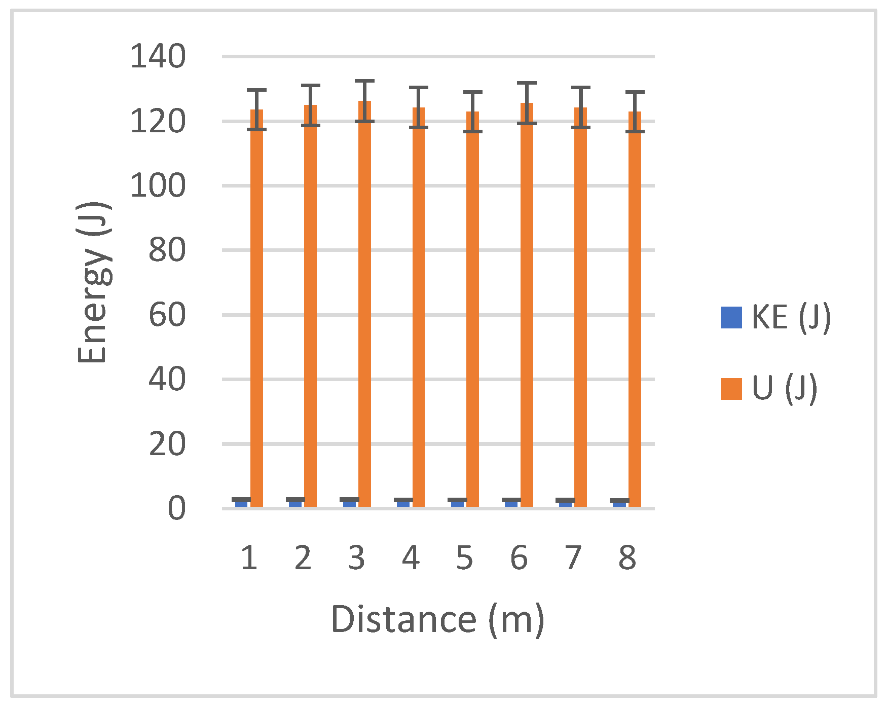
Figure 12.
Comparative measurements of capacitor energy (U) and measured kinetic energy (KE) with lidar modulation.
Figure 12.
Comparative measurements of capacitor energy (U) and measured kinetic energy (KE) with lidar modulation.

Figure 13.
Direct comparison of modulated and unmodulated kinetic energies.
Disclaimer/Publisher’s Note: The statements, opinions and data contained in all publications are solely those of the individual author(s) and contributor(s) and not of MDPI and/or the editor(s). MDPI and/or the editor(s) disclaim responsibility for any injury to people or property resulting from any ideas, methods, instructions or products referred to in the content. |
© 2024 by the authors. Licensee MDPI, Basel, Switzerland. This article is an open access article distributed under the terms and conditions of the Creative Commons Attribution (CC BY) license (https://creativecommons.org/licenses/by/4.0/).
Share and Cite
MDPI and ACS Style
LaRocco, J.; Tahmina, Q.; Simonis, J. Evaluating a Controlled Electromagnetic Launcher for Safe Remote Drug Delivery. Technologies 2024, 12, 69. https://doi.org/10.3390/technologies12050069
AMA Style
LaRocco J, Tahmina Q, Simonis J. Evaluating a Controlled Electromagnetic Launcher for Safe Remote Drug Delivery. Technologies. 2024; 12(5):69. https://doi.org/10.3390/technologies12050069
Chicago/Turabian StyleLaRocco, John, Qudsia Tahmina, and John Simonis. 2024. "Evaluating a Controlled Electromagnetic Launcher for Safe Remote Drug Delivery" Technologies 12, no. 5: 69. https://doi.org/10.3390/technologies12050069
Note that from the first issue of 2016, this journal uses article numbers instead of page numbers. See further details here.