
Analysis of Kinematics and Dynamics of Rolling Ring Based on Finite Element Method
1
School of Materials Science and Engineering, Central South University, Changsha 410083, China
2
CSSC Jiujiang Marine Equipment (Group) Co., Ltd., No. 1699 Changjiang Road, Jiujiang 332005, China
3
Aerospace Systems Engineering Shanghai, Shanghai 201108, China
4
State Key Laboratory of Powder Metallurgy, Central South University, Changsha 410083, China
*
Author to whom correspondence should be addressed.
Electronics 2024, 13(7), 1235; https://doi.org/10.3390/electronics13071235
Submission received: 24 November 2023
/
Revised: 23 February 2024
/
Accepted: 28 February 2024
/
Published: 27 March 2024
(This article belongs to the Special Issue Mechatronic Control Engineering Volume II)
Abstract
:The working performance of the conductive rolling ring has a crucial impact on the overall energy security and on-orbit life of a satellite. To ensure the real-time transmission of signal and current, it is necessary to control the motion pattern of the rolling ring. In this paper, the finite element analysis method is used to carry out kinematics and dynamics simulation analysis, analyze the motion stability of the rolling ring, and discuss the relationship between the size of the idler gear, the driving torque, and the flexible contact pressure. The research results show that the numerical simulation and theoretical analysis show that the deviation angle is between 0 and 1.52 when the initial installation of the rolling ring is deviated by using the existing camber design of the inner and outer rings. Both have a self-recovery function. The driving torque and the size of the idler gear are nonlinear, and the contact force is proportional to the radius of the idler gear. With the increase in the compression of the radius of the flexible ring, the driving torque and the contact force will increase accordingly. The method of reducing the compression or increasing the size of the idler gear can be used to reduce the driving torque and maintain a certain contact to facilitate the transmission of electrical signals.
1. Introduction
As the core part of the signal transmission of the spacecraft system, the conductive ring is mainly used to transmit electric power and signals between the relatively rotating solar panels and the stars. It is one of the few single-point failure links of the whole satellite [1]. Its reliability is directly related to the success of the mission of the whole satellite, and it is a veritable “lifeline” of the aircraft. The precision conductive ring is a precision transmission device that realizes the transmission of images, data signals, and power between two relative rotating mechanisms. It is especially suitable for unrestricted continuous rotation and also needs to transmit data signals or power from the fixed position to the rotating position [2]. In response to the new requirements of the new generation of long-life satellites for high reliability and long life of key components, there is a huge demand for conductive rings in terms of design methods, new material development, tribological properties, long-life maintenance, and high-precision manufacturing processes [3]. The large friction force of the slip ring will seriously affect its performance. Therefore, it is necessary to develop a rolling ring structure to solve the problem of large friction strength.
At present, many scholars are studying the characteristics of the slip ring. Sun Bin [4] took the contact form of the contact and conductive ring as the research object, abstracted the contact between the contact and conductive ring as the geometric model of contact between the arc concave and hemisphere, combined it with the formula of Hertz contact stress of deep groove ball bearing, and generated an analytical formula of contact between the arc concave and hemisphere. Liu Xingfu [5] tested the transmission reliability of the power ring and the signal ring under the friction pair of the brush wire and the brush wire tow with two different brush wire structures at the end of the life test. The high-vacuum and low-temperature environment, set according to the different working conditions in orbit, simulate the specific power on the satellite, test the power supply stability of the conductive slip ring power ring and the transmission error code of the common signal after passing through the signal ring, and provide the basis for the structural design of the conductive slip ring-positive product-matching friction pair. Yin Nian [6] studied the friction and wear behavior of the conductive slip ring Au-Au coating at different temperatures and different friction speeds using a molecular dynamics simulation method and simulated the effect of arc erosion in current-carrying friction by setting a model to locally rapidly increase temperature. The research results provide a reference basis for revealing the changing microscopic mechanism of the friction and wear properties of Au-Au coating with temperature and speed and provide a theoretical basis for the design of long-life and high-reliability satellites in China. Chen [7] proposed a machine vision-aided method to measure the ring groove position as the brush alignment target and track the relative brush position deviation during the manual brush alignment assembly process. A vision-assisted brush alignment component system has also been developed to provide quantitative position deviation for the accurate alignment of brushes and ring grooves, ensuring higher alignment accuracy and efficiency. Argibay [8] used a customized friction meter to test the macro-brush and slip ring sliding electrical contact at a relatively high speed and current density and studied the wear phenomenon of high-current density self-matching metal copper sliding contact in a wet carbon dioxide environment. Wang [9] studied the essential characteristics and potential distribution of the electric field in slip ring assembly. An optimization scheme for the aluminum shielding structure, insulating baffle, and grounding structure is proposed. Li [10] proposed a brush angle measurement and control method based on machine vision. Zhang [11] proved that crystalline nanocrystals have higher electromagnetic compatibility in slip rings compared with other magnetic materials. At the same time, this paper also discusses the structural design of a noncontact slip ring. Balakrishna A [12] performed a finite element-based static and modal analysis of automotive leaf springs using the ANSYS workbench. Von Mises stresses, total deformation, and weight reduction in the leaf springs were evaluated for different geometries, materials, and loading conditions. Rehab I [13] developed a nonlinear dynamic model of 5-DOF deep groove ball bearings for numerical analysis when radial clearance increased and found that the vibration of fault characteristic frequency was inconsistent with the consensus under different clearance increases. Wang R [14] designed, manufactured, and experimented with gas static thrust bearings with a microhole limiter. This study provides the experimental basis for the practical application of gas static thrust bearings with microhole limiters under the thickness of micro-gas film. As can be seen from the above, there are few simulation analyses on the kinematics and dynamics of the conductive rolling ring. Therefore, this study first carries on the motion theory analysis and then uses the finite element analysis method to carry out the kinematics and dynamics simulation analysis. Finally, the relationship between idler gear wheel size, driving torque, and the flexible contact pressure is discussed.
2. Motion Stability Theory
Stability is an extremely important characteristic of the system, and the analysis of system motion stability is an important part of the system and control theory. There are two definitions of system stability:
- The external stability is characterized by an input–output relationship;
- Internal stability is represented by state motion under zero input conditions.
For linear time-invariant systems, x (0) is known, and
y = Cx = Du
For no input u (t) = 0, and when the initial state is any, the state response is
The system is said to be internally stable, and the system is internally asymptotically stable. Differential equation . The necessary and sufficient condition for the asymptotic stability of A is that all eigenvalues of matrix A have negative real parts. If the linear time-invariant system is internally stable, it must be externally stable [15].
3. Model Building and Meshing
As shown in Figure 1, the model is composed of three parts: an external conductive ring, an internal conductive ring, and a flexible ring.
The flexible ring is located between the inner conductive ring and the outer conductive ring. The inner and outer conductive rings and the flexible ring have a certain cross-section shape, and the design unit is mm. The relative position is shown in Figure 2.
The model is composed of three parts. The inner conductive ring is a rigid body, and the outer conductive ring is also a rigid body. In this problem, the inertia of the inner conductive ring and the outer conductive ring is not important and can be taken arbitrarily. Based on the conductive property of the flexible ring, it is endowed with copper material, which has excellent conductive properties and good wear resistance. The contact boundary conditions of the flexible ring were set with the outer conducting ring, the inner conducting ring, and the idler, respectively. The contact type was defined as surface-to-surface contact, and the contact method was selected as the penalty function method.
The flexible ring is discretized by beam elements. In the calculation, there are 120 elements in the circumferential direction and 2 elements in the axial direction, totaling 240 elements. As shown in Figure 2, Figure 3 and Figure 4, the thickness of the shell is 0.3 mm of the thickness of the flexible ring. The numerical calculation shows that after dividing the flexible ring into 80 elements, the difference between the displacement calculation results of each point in the flexible ring and the bending moment calculation results of the beam section is very small, so 120 elements in the phantom direction can meet the grid convergence requirements.
4. Kinematics and Dynamics Simulation
4.1. Motion Stability Analysis
In addition, in the initial installation process of the flexible ring, due to the assembly deviation, there may be a certain deviation or inclination, which will seriously affect the overall motion performance of the rolling ring. Therefore, the motion stability of the flexible ring is simulated and analyzed to determine whether the flexible ring can automatically adjust to the appropriate motion state during the motion process.
Given the above analysis, the motion analysis of the flexible ring is carried out under three working conditions, namely, the x-axis, y-axis, and x-axis and y-axis have a certain deflection. The analysis model is shown in the following figure.
It can be seen from Figure 5 and Figure 6, for the above three working conditions, the kinematic analysis of the flexible ring is carried out. The motion trajectory of each point of the flexible ring is shown in the following figures.
It can be seen from Figure 7, Figure 8 and Figure 9, according to the motion analysis of the above three working conditions (y-axis offset 1 degree, x-axis offset 1 degree, and around the XY-axis offset 1 degree), the flexible ring can return to the normal working position through the adaptive method under the condition that the initial position has a certain deflection.
The adaptive principle and stress of the flexible ring under the deflection condition are analyzed. When the flexible ring has an initial assembly error of 1 degree around the x-axis and y-axis, there is a rotation moment when the flexible ring deviates from the horizontal position, which makes it automatically return to the horizontal position, as shown in Figure 10 and Figure 11. Under the action of the above two sets of moments, the flexible ring has a certain degree of motion adaptability.
In addition, according to the existing power rolling ring structure, the maximum deflection angle of the flexible ring is 1.52°. According to the simulation analysis of the position of the flexible ring under this condition, the flexible ring can also automatically adjust its normal working position. Therefore, the size of the simulated skew angle can predict the actual operation of the conductive roller ring.
4.2. Dynamic Analysis of Driving Torque and Contact Pressure
The rolling ring is discretized into a 90-segment beam element. Contact is applied between the rolling ring and inner ring, outer ring, and idler gear. The rolling ring is assembled between the inner ring, the outer ring, and the idler gear. The inner ring is driven to make the rolling ring rotate at a uniform speed.
Figure 12 is an analysis of the initial installation status of the rolling ring: 12 flexible rings are installed between the guide rail and the idler gear. The flexible ring, guide rail, and idler gear are in contact with each other to achieve balance.
4.2.1. Dynamic Analysis of the Relationship between Idler Gear Size and Driving Torque
The flexible ring compression is selected as 0.5 mm, and the kinematics and dynamics analysis is carried out for different dimensions of the idler gear.
As shown in Figure 13, the whole mechanism includes an inner conductive ring, outer conductive ring, 14 flexible rings, 14 idler gear, and guide rails. The contact between the flexible ring and the inner and outer rings is metal to metal, and the friction coefficient is 0.3. Take the friction coefficient between the flexible ring and the idler gear and between the idler gear and the guide rail as 0.1.
From the simulation results, there is no relative sliding between the flexible ring and the inner and outer rings, as well as between the flexible ring and the idler gear, and there is certain relative sliding between the idler gear and the guide rail, as shown in Figure 14.
The dimension marked with * is the position dimension of the idler gears arc, which varies from 7.0 mm to 7.5 mm.
To understand the relationship between the dimensions of different idler gears and the driving torque, we analyzed the driving torque of idler gears with dimensions of 7.0 mm, 7.2 mm, and 7.5 mm.
As shown in Figure 15, it can be seen from Table 1 that the relationship between the size of the idler gear and the driving torque is nonlinear, and the size of the idler gear has a relatively large impact on the driving torque. The drive torque and the size of the idler gear have a nonlinear relationship. When the idler gear radius is 7 mm, the driving torque is 33 N mm. As the radius of the idler gear increases to 7.5 mm, the driving torque reaches 364 N mm. Therefore, in the actual design process, it can be selected according to different needs.
4.2.2. Dynamic Analysis of the Relationship between the Size of the Idler Gear and the Contact Pressure of the Flexible Ring
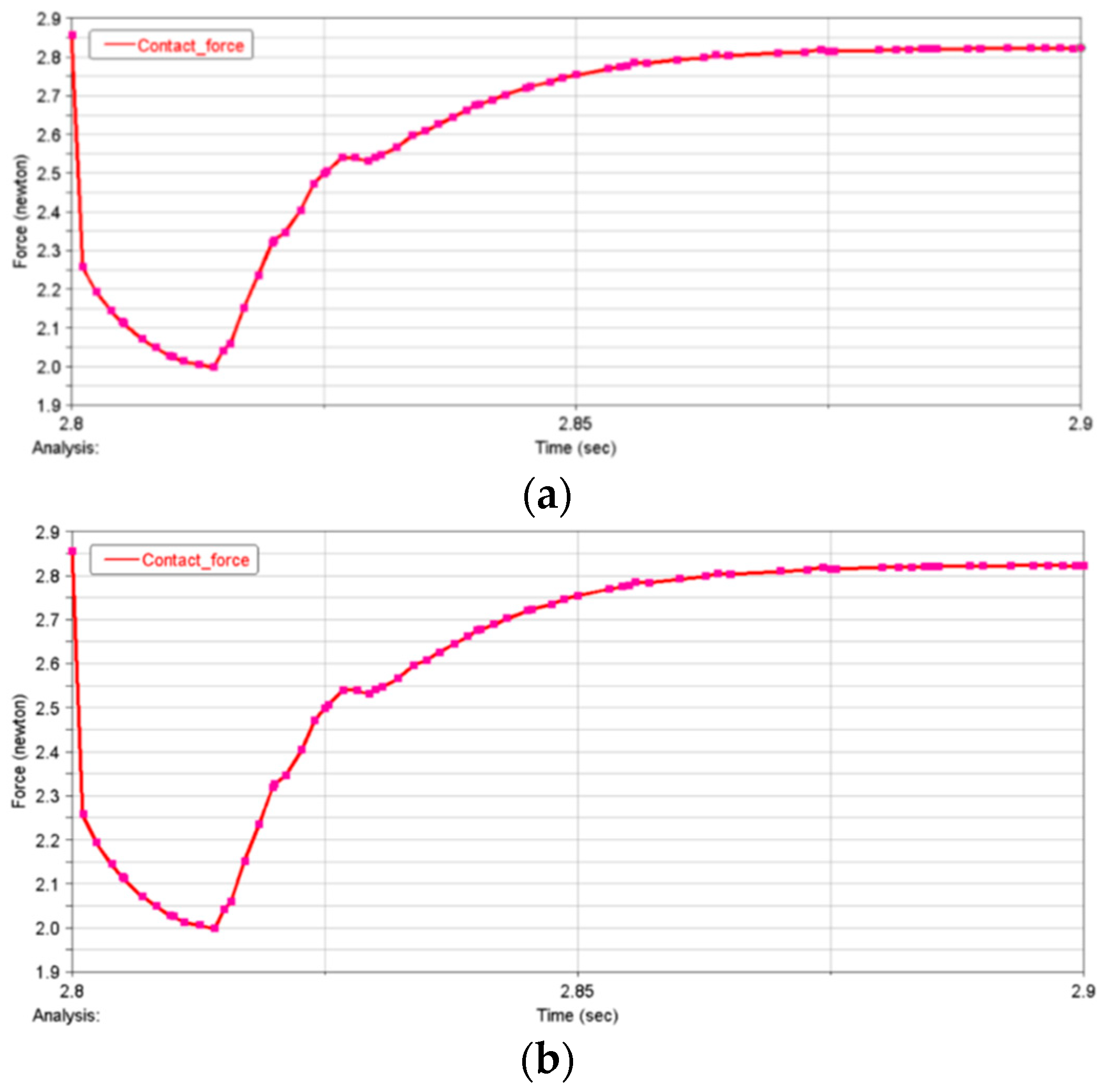
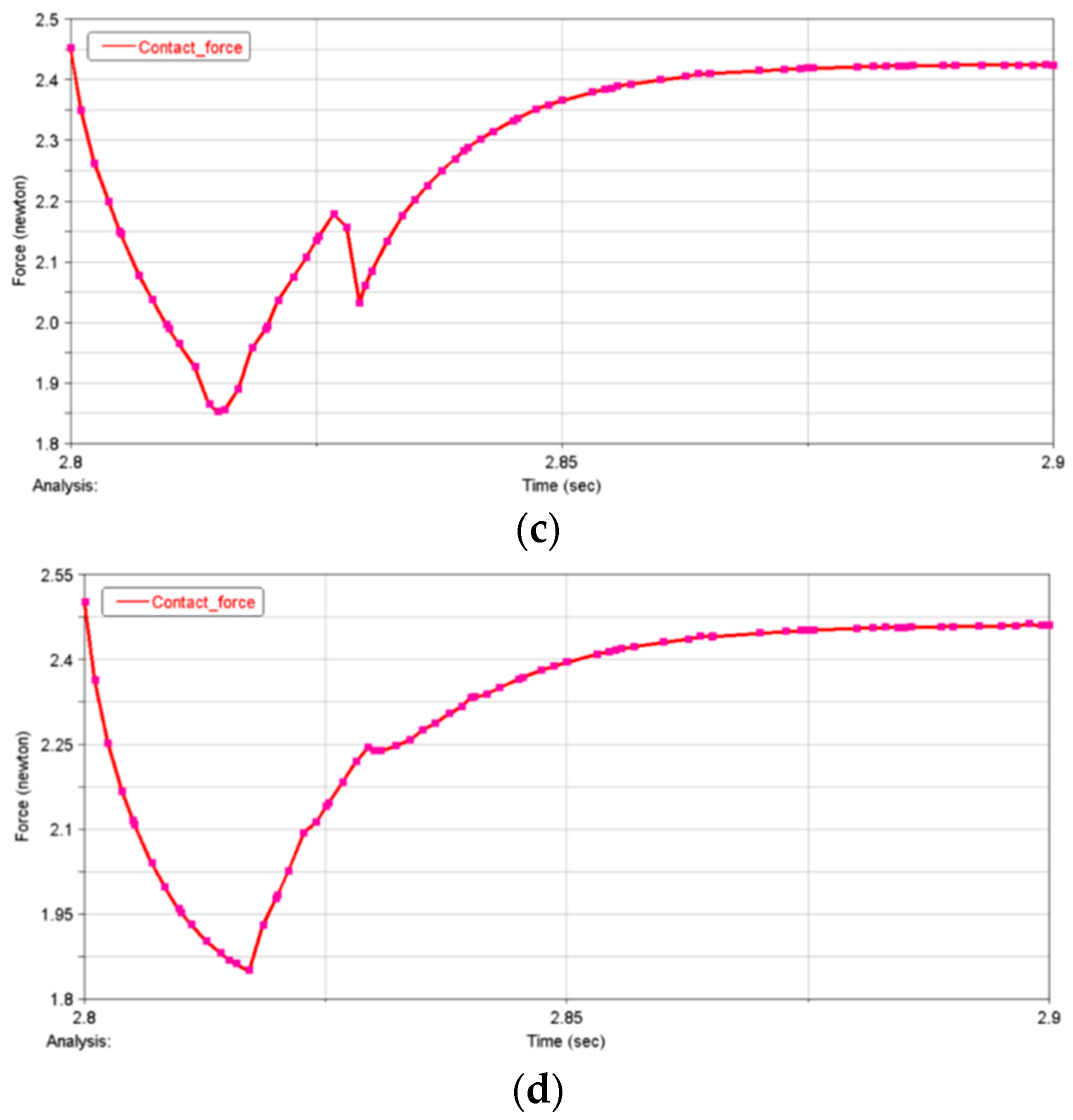
To study the relationship between the radius size of the idler gear and the contact force of the moving parts inside the rolling ring, the relevant dynamic simulation calculation was carried out. The following results are obtained through analysis. The first half of the curve in the figure represents the change in force at initial contact, and the second half is the contact force after a stable state. Therefore, the first half of the curve can be ignored, and only the stable value after observation is needed.
It can be seen from Figure 16, Figure 17 and Figure 18, according to the above analysis results, the relationship between the contact pressure of the flexible ring and the size of the idler gear can be obtained as shown in Table 2. The following conclusions can be drawn: the contact force is proportional to the radius of the idler gear, and the two can be approximately linear. The maximum contact force of the idler gear reaches 9.1 N. Therefore, the corresponding selection can be made according to the needs of the design process.
Table 3 shows the relationship between a flexible ring with different compression and driving torque and contact pressure.
It can be seen from the above analysis that the driving torque and contact force will increase with the increase in the radius of the flexible ring and the increase in compression. The maximum driving torque reaches 18.9 N mm, the maximum contact pressure of the idler gear reaches 18.9 N, and the maximum contact pressure of the inner and outer rings reaches 19 N. Therefore, the size of the flexible ring should be determined according to the design requirements, and the driving torque of the drive system should also be evaluated. For those requiring small driving torque and maintaining certain contact to facilitate the transmission of electrical signals, the method of reducing the compression amount or increasing the size of the idler gear can be adopted.
5. Discussion
In conductive roller rings in dynamic analysis, the roller rings are discrete into 90 beam units, and forces are applied by contact between the roller rings and the inner ring, the outer ring, and the driven gear. The roller ring is assembled between the inner ring, the outer ring, and the driven gear, and the inner ring is driven to make the roller ring rotate at a constant speed. In the theory of motion stability, stability is an extremely important characteristic in systems, and the analysis of system motion stability is an important part of system and control theory. There are two definitions of system stability: one is the external stability characterized by the input–output relationship; the second is the internal stability characterized by the state motion under zero input conditions. In the modeling and meshing, the model consists of three parts: an external conducting ring, an internal conducting ring, and a flexible ring. The inner conducting ring is a rigid body, and the outer conducting ring is also a rigid body. In this problem, the inertia of the inner and outer conducting rings is not important and can be arbitrarily valued. The flexible ring is discretized by the shell element. In the motion stability analysis, the adaptive principle and stress of the flexible ring under deflection are analyzed. When the flexible ring has an initial assembly error of 1 degree around the x and y axes when the flexible ring deviates from the horizontal position, a rotating torque will be generated, making it automatically return to the horizontal position. Under the action of the above two groups of forces, the flexible ring has certain motion adaptability. Therefore, the conductive roller ring has the following advantages:
- (1)
- Flexible rotation: The conductive roller ring can realize the free rotation of the rotating part through the auxiliary role of the idler and can realize the function of self-recovery within a certain inclination range while maintaining the transmission of power or signal.
- (2)
- Low-loss transmission: The conductive roller ring can achieve low-loss power or signal transmission through the structural design of the rolling form. Conductive roller rings provide more stable and efficient transmission performance than traditional lead or sliding electrical contacts.
- (3)
- Multi-channel transmission: Some conductive roller rings can also achieve multi-channel transmission, that is, multiple independent power or signal paths are transmitted simultaneously in the same device. This design can meet the needs of multiple signal transmissions in complex systems and improve the overall performance and reliability of the system.
This study focuses on analyzing the influence of assembly of different sizes on conductive roller rings, but the future research directions mainly include the following points:
- (1)
- Optimization of the design method: Research the design method of conductive rings with higher reliability and long life to meet the needs of a new generation of long-life satellites;
- (2)
- New material development: Explore new materials to improve the performance of conductive roller rings, reduce friction and wear, and thus improve the service life of satellites;
- (3)
- Tribological performance: Observe the friction and wear behavior of conductive roller rings at different temperatures and speeds to provide a theoretical basis for the design of long-life satellites;
- (4)
- Long-life maintenance: Study the long-term use and maintenance methods of conductive roller rings to ensure high reliability and stability over a long period;
- (5)
- High-precision manufacturing process: Explore high-precision manufacturing processes to improve the processing accuracy of conductive roller rings, reduce installation errors, and improve the stability and reliability of signal transmission;
- (6)
- Noncontact transmission: research the design of noncontact conductive roller rings to reduce friction and wear and improve the stability and reliability of signal transmission.
6. Conclusions
In this paper, kinematics and dynamics simulation analyses are carried out using the finite element analysis method, the motion stability of the rolling ring is analyzed, and the relationship between idler gear size, driving torque, and flexible contact pressure is discussed. The following conclusions are drawn:
- (1)
- Both numerical simulation and theoretical analysis show that, with the existing camber design of the inner and outer rings, when the initial installation of the rolling ring has a deviation, the deviation angle has a self-recovery function; that is, the lateral motion is stable. The maximum deflection angle of the flexible ring is 1.52°.
- (2)
- The contact force is proportional to the radius of the idler gear, and the two can be approximately linear. The maximum contact force of the idler gear reaches 9.1 N. Therefore, the corresponding selection can be made according to the needs of the design process.
- (3)
- The drive torque and the size of the idler gear have a nonlinear relationship. The larger the size of the idler gear, the greater the required drive torque. The maximum driving torque is 364 N mm.
- (4)
- With the increase in the radius compression of the flexible ring, the driving torque and contact force increase correspondingly. The maximum driving torque reaches 18.9 N mm, the maximum contact pressure of the idler gear reaches 18.9 N, and the maximum contact pressure of the inner and outer rings reaches 19 N.
- (5)
- For the case that the driving torque is small and a certain contact is required to facilitate the transmission of electrical signals, the method of reducing the amount of compression or increasing the size of the idler gear can be adopted.
Author Contributions
H.W. drafted, designed, and created the manuscript and analyzed the data. C.L. and Z.Q. analyzed the data and supervised this study. X.K. conceived the project, and H.L. organized the paper and edited the manuscript. All authors have read and agreed to the published version of the manuscript.
Funding
This work was supported by the Major Science and Technology Projects of Jiangxi Province (20223AAE01002).
Data Availability Statement
The original contributions presented in the study are included in the article material. Further inquiries can be directed to the corresponding author.
Acknowledgments
This article is grateful for the technical support from the ICFPMCE2023+Electronics.
Conflicts of Interest
Author Haihong Wu was employed by the company CSSC Jiujiang Marine Equipment (Group) Co., Ltd. The remaining authors declare that the research was conducted in the absence of any commercial or financial relationships that could be construed as a potential conflict of interest.
References
- Lu, J.; Xing, L.; Li, Y.; Ge, F. Key technologies and development trends of precision conductive slip rings. Navig. Control 2015, 14, 20–26. [Google Scholar]
- Tang, F.; Jiang, Y. Design of radar combiner ring on a helicopter. Electron. Mech. Eng. 2010, 26, 30–32. [Google Scholar]
- Sun, Y.; Wang, Y.; Sun, X.; Liu, X.; Yu, J. Research on failure modeling and process optimization of conductive slip rings for aerospace. J. Mech. Eng. 2020, 56, 1–12. [Google Scholar]
- Sun, B.; Feng, J.; Shen, T.; Shen, Z. Contact mechanics analysis of conductive slip ring based on contact. Nav. Electron. Countermeas. 2022, 45, 117–120. [Google Scholar] [CrossRef]
- Liu, X.; Zhu, Y.; Liu, H.; Zhao, L.; Xie, Z. Transmission reliability evaluation of spaceborne long-life conductive slip ring. Opt. Precis. Eng. 2019, 27, 2028–2035. [Google Scholar]
- Yin, N.; Zhang, Z.; Zhang, J. Molecular dynamics simulation of friction and wear behavior of conductive slip ring Au coating. J. Tribol. 2018, 38, 108–114. [Google Scholar] [CrossRef]
- Chen, X.; Wang, Y.; Sheng, Y.; Yu, C.; Yang, X.; Xi, J. Vision-Aided Brush Alignment Assembly System for Precision Conductive Slip Rings. Machines 2022, 10, 393. [Google Scholar] [CrossRef]
- Argibay, N.; Bares, J.A.; Sawyer, W.G. Asymmetric wear behavior of self-mated copper fiber brush and slip-ring sliding electrical contacts in a humid carbon dioxide environment. Wear 2010, 268, 455–463. [Google Scholar] [CrossRef]
- Wang, J.; Liu, R.; Xiao, R.; Ping, A.; Liu, J.; Zhang, M.; Li, Q. Optimized Design of Slip Ring Assembly for Aerospace to Reduce Deep Dielectric Charging. IEEE Trans. Nucl. Sci. 2022, 69, 915–924. [Google Scholar] [CrossRef]
- Li, J.; Li, J.; Wang, X.; Tian, G.; Fan, J. Machine Vision-Based Method for Measuring and Controlling the Angle of Conductive Slip Ring Brushes. Micromachines 2022, 13, 447. [Google Scholar] [CrossRef] [PubMed]
- Zhang, J.; Zhang, X.; Zhu, C.; Song, K.; Zhou, T. Research on Electromagnetic Compatibility of Non-Contact Slip Ring. In Proceedings of the International Conference on Intelligent Computing, Automation and Systems (ICICAS), Chongqing, China, 29 December–31 December 2021; IEEE: Piscataway, NJ, USA, 2021; pp. 318–321. [Google Scholar]
- Balakrishna, A.; Mishra, P.K. Modelling and analysis of static and modal responses of leaf spring used in automobiles. Int. J. Hydromechatron. 2021, 4, 350–367. [Google Scholar] [CrossRef]
- Rehab, I.; Tian, X.; Gu, F.; Ball, A.D. The influence of rolling bearing clearances on diagnostic signatures based on a numerical simulation and experimental evaluation. Int. J. Hydromechatron. 2018, 1, 16–46. [Google Scholar] [CrossRef]
- Wang, R.; Yu, H.; Wang, G.; Zhang, G.; Wang, W. Study on the dynamic and static characteristics of gas static thrust bearing with micro-hole restrictors. Int. J. Hydromechatron. 2019, 2, 189–202. [Google Scholar] [CrossRef]
- Zhong, W.; Yao, W. Methodology of applied mechanical dual system. Proc. Mech. Hist. Methodol. 2003, 37, 133–141. [Google Scholar]
Figure 1.
Overall view of the model.

Figure 2.
Model size and relative position.
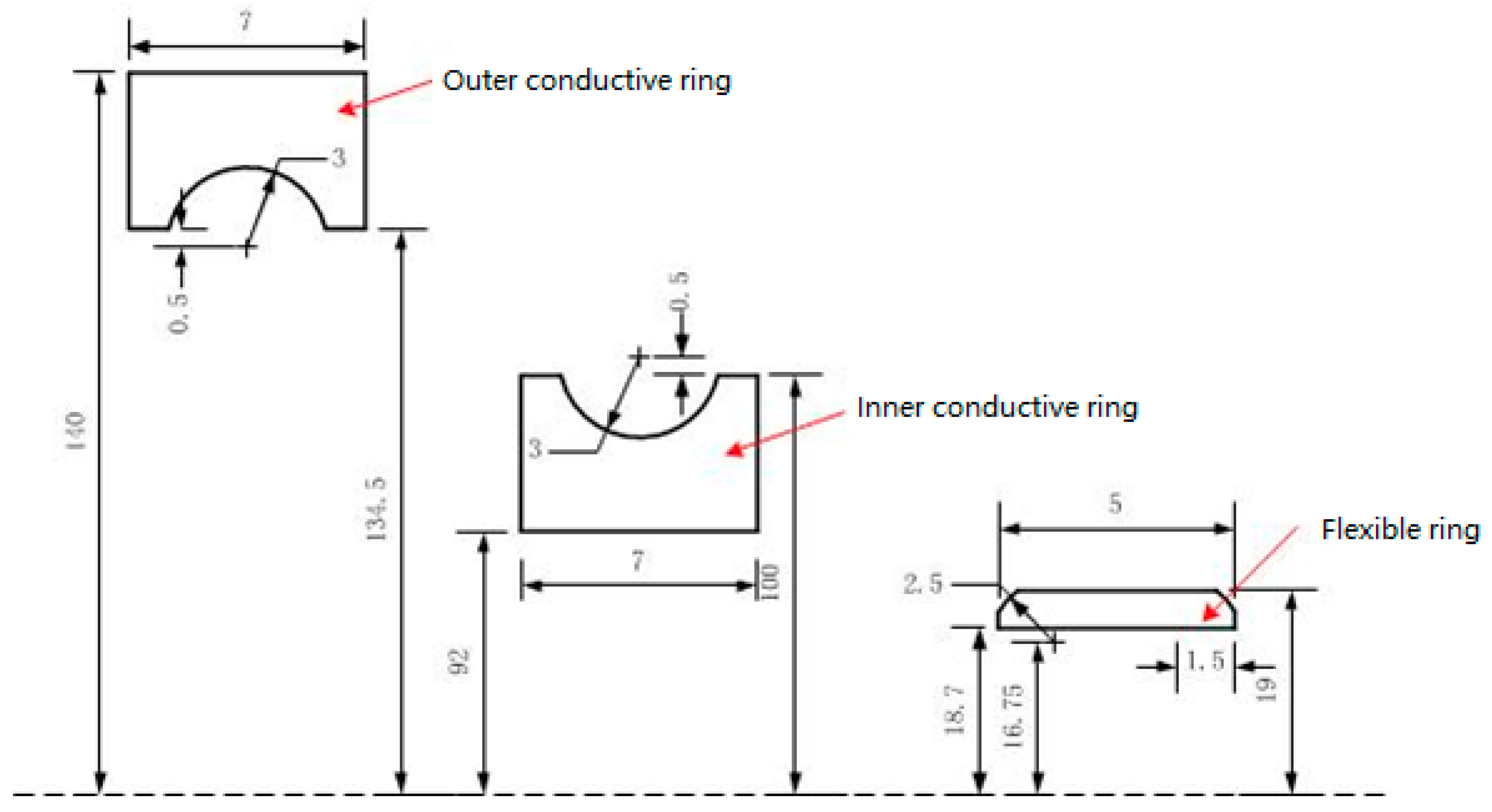
Figure 3.
Flexible ring grid distribution.

Figure 4.
Schematic diagram of 1-degree offset of the flexible surrounding.

Figure 5.
Schematic diagram of flexible surrounding x-axis offset by 1 degree.
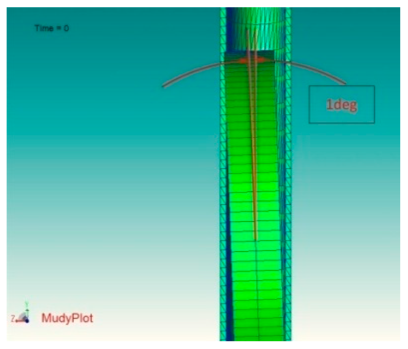
Figure 6.
Schematic diagram of the flexible surrounding x-axis and y-axis offset by 1 degree.

Figure 7.
The movement track of a point on the flexible ring when the initial deviation is 1 degree around the y−axis.
Figure 7.
The movement track of a point on the flexible ring when the initial deviation is 1 degree around the y−axis.
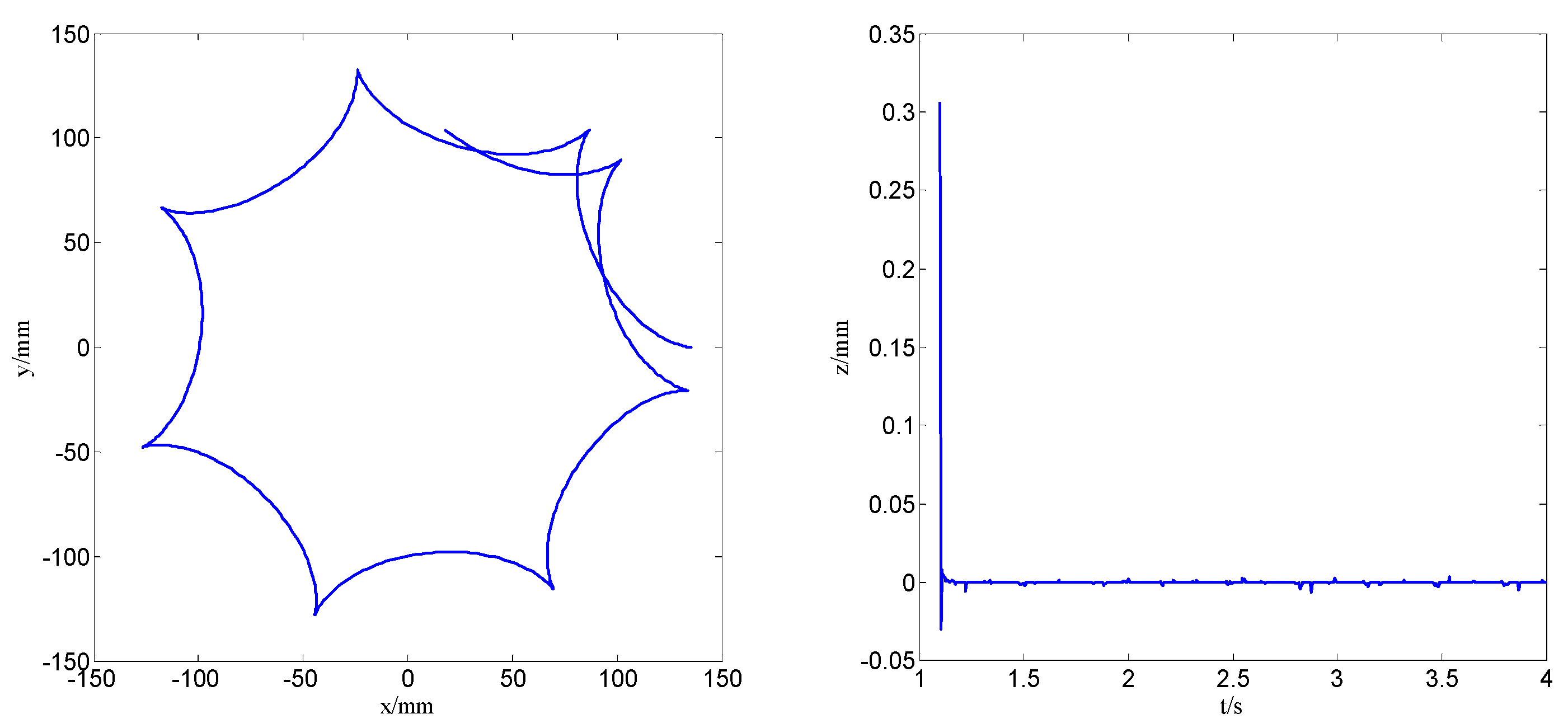
Figure 8.
The movement track of a point on the flexible ring when the initial deviation is 1 degree around the x−axis.
Figure 8.
The movement track of a point on the flexible ring when the initial deviation is 1 degree around the x−axis.

Figure 9.
The motion track of a point on the flexible ring when it is offset by 1 degree around the x−axis and y−axis, respectively.
Figure 9.
The motion track of a point on the flexible ring when it is offset by 1 degree around the x−axis and y−axis, respectively.

Figure 10.
Moment for automatic recovery of the flexible surrounding y-axis.

Figure 11.
Moment for automatic recovery of the flexible surrounding x-axis.
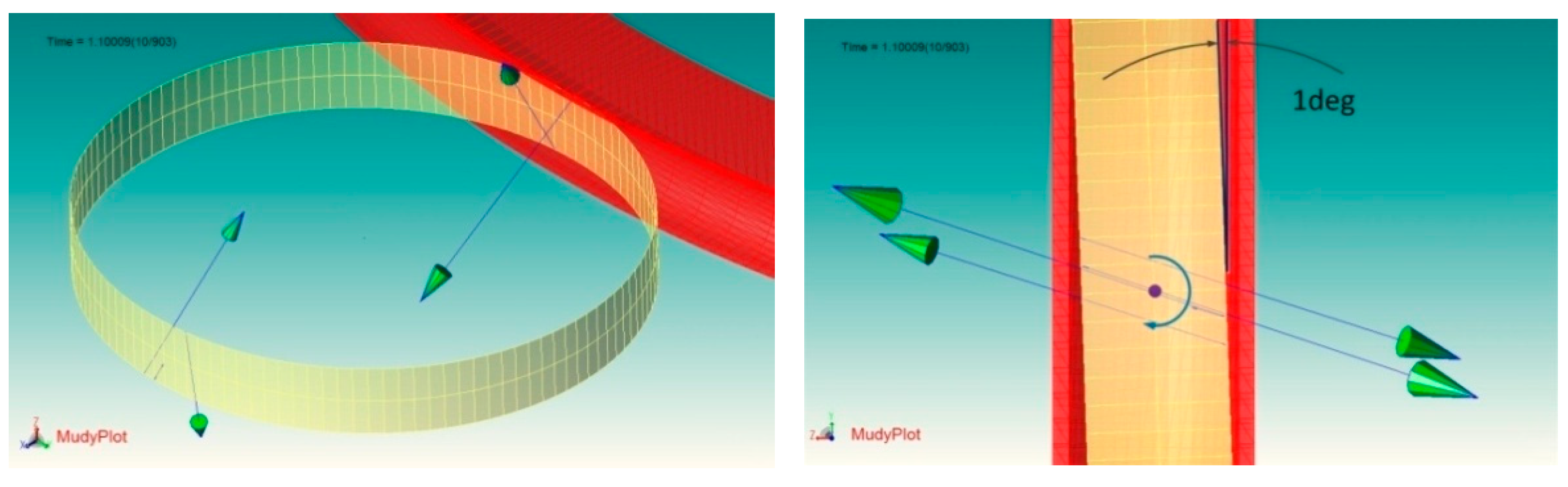
Figure 12.
Rolling ring module modeling diagram. (a) Local model diagram of the initial state of the rolling ring; (b) Overall model diagram.
Figure 12.
Rolling ring module modeling diagram. (a) Local model diagram of the initial state of the rolling ring; (b) Overall model diagram.
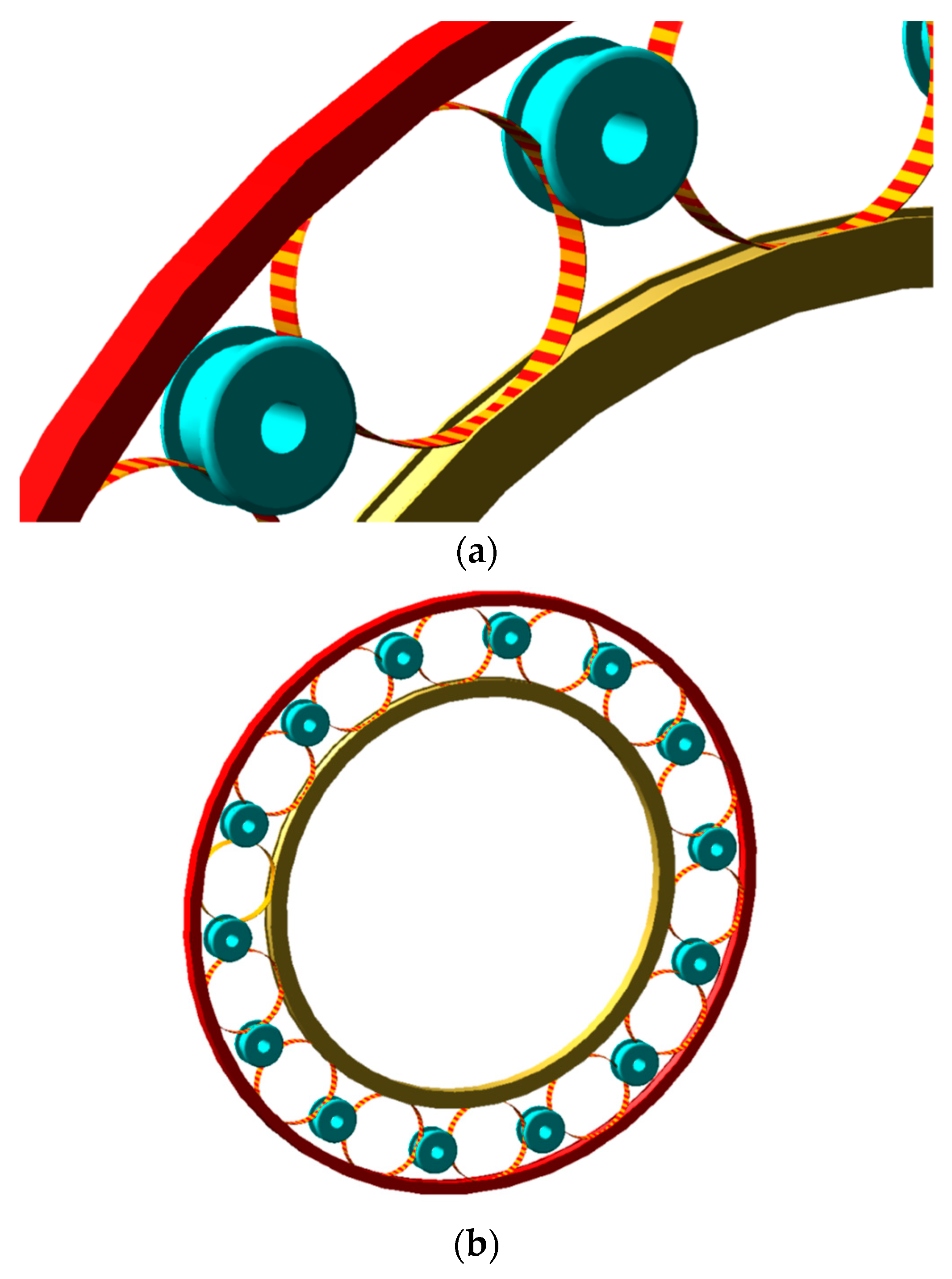
Figure 13.
Mechanism movement process.
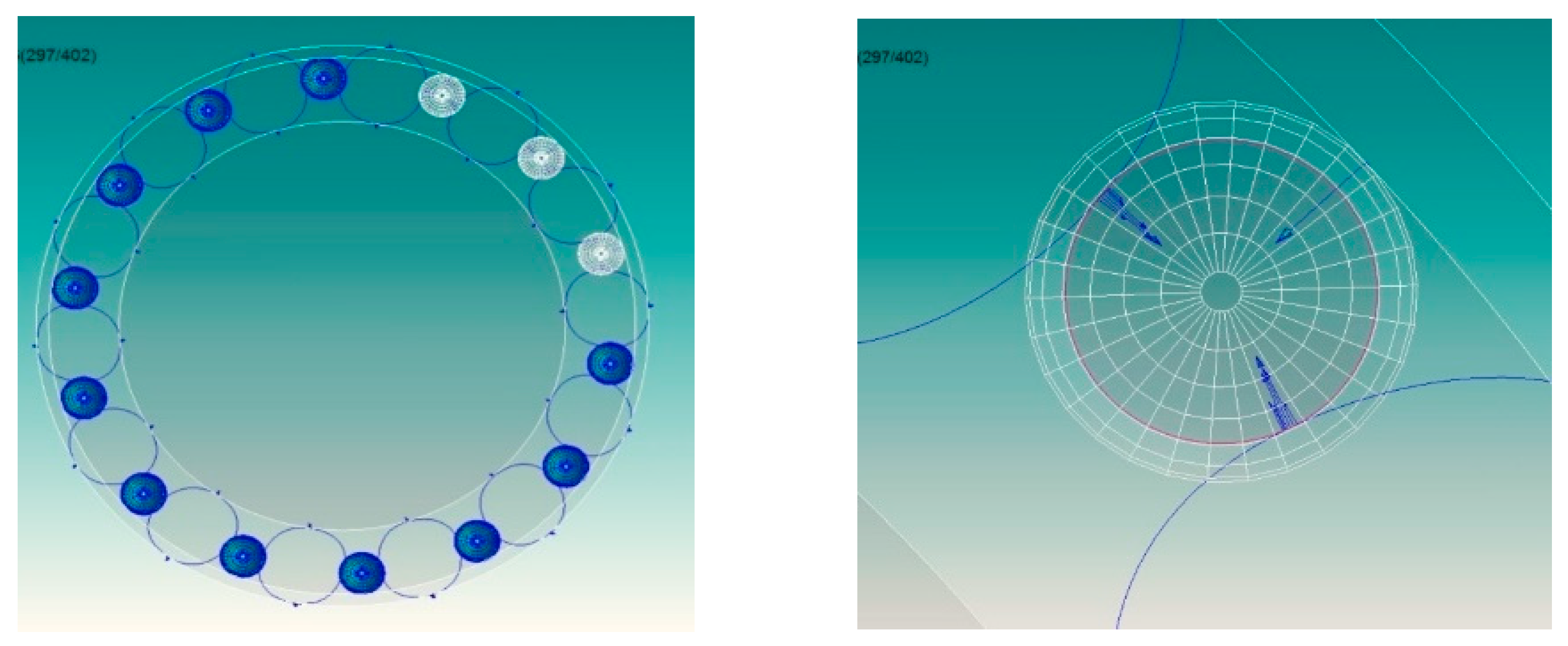
Figure 14.
Relative movement between idler gear and guide rail.

Figure 15.
Relationship between idler gear size and drive torque. (a) Drive torque when the idler gear size is 7.5 mm; (b) Drive torque when the idler gear size is 7.2 mm; (c) Drive torque when idler gear size is 7.0 mm.
Figure 15.
Relationship between idler gear size and drive torque. (a) Drive torque when the idler gear size is 7.5 mm; (b) Drive torque when the idler gear size is 7.2 mm; (c) Drive torque when idler gear size is 7.0 mm.
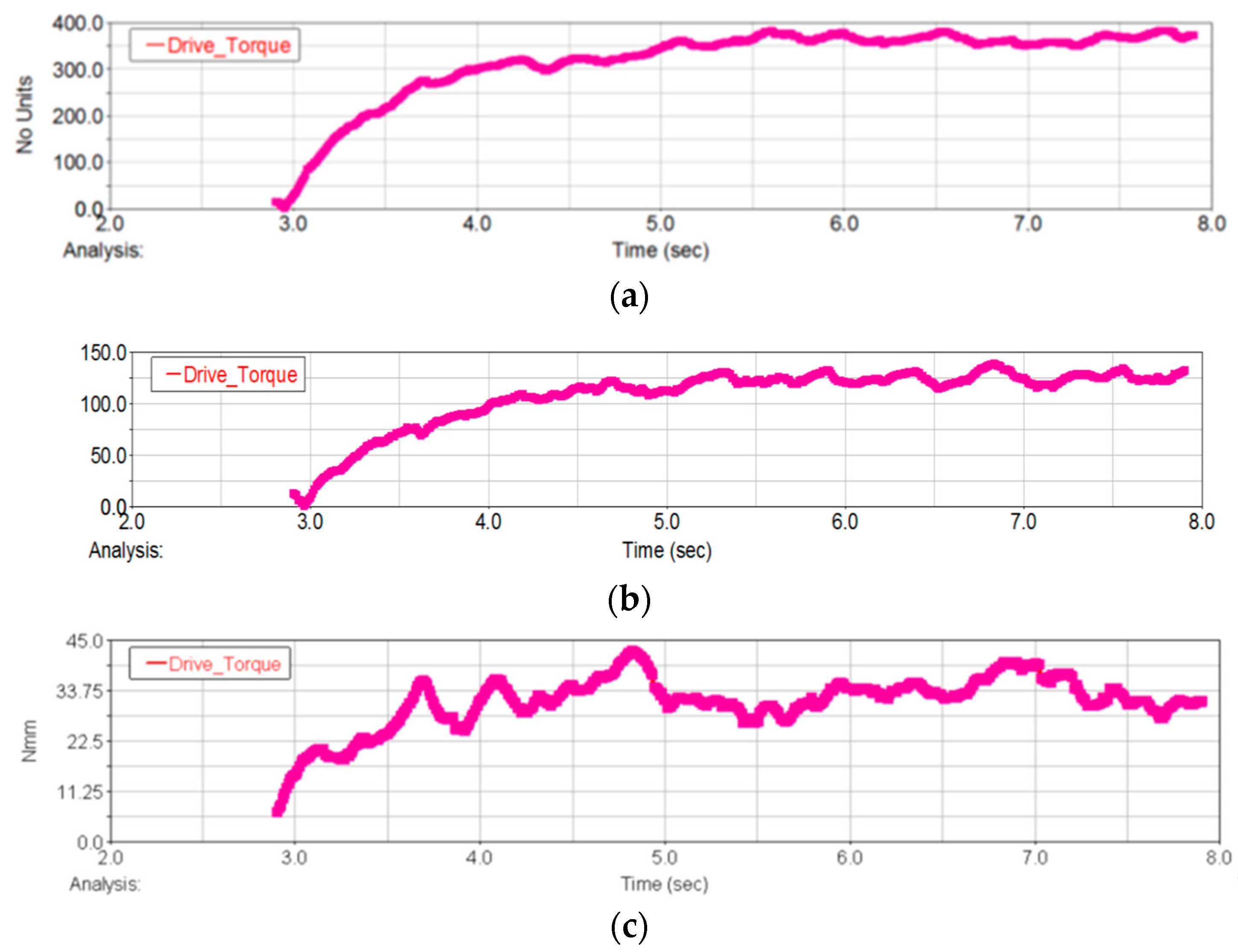
Figure 16.
Relationship between idler gear size and contact force of roller ring (radius of idler gear 7.5 mm). (a) Contact force between the flexible ring and outer ring; (b) Contact force between the flexible ring and inner ring; (c) Contact force between the flexible ring and left idler gear; (d) Contact force between the flexible ring and the right idler gear.
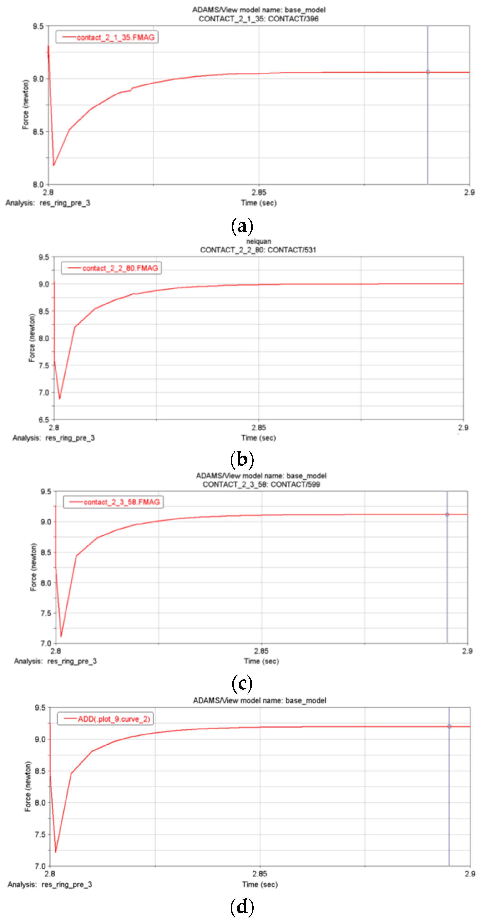
Figure 17.
Relationship between idler gear size and contact pressure of flexible ring (radius of idler gear 7.2 mm). (a) Contact force between the flexible ring and outer ring; (b) Contact force between the flexible ring and inner ring; (c) Contact force between the flexible ring and left idler gear; (d) Contact force between the flexible ring and right idler gear.

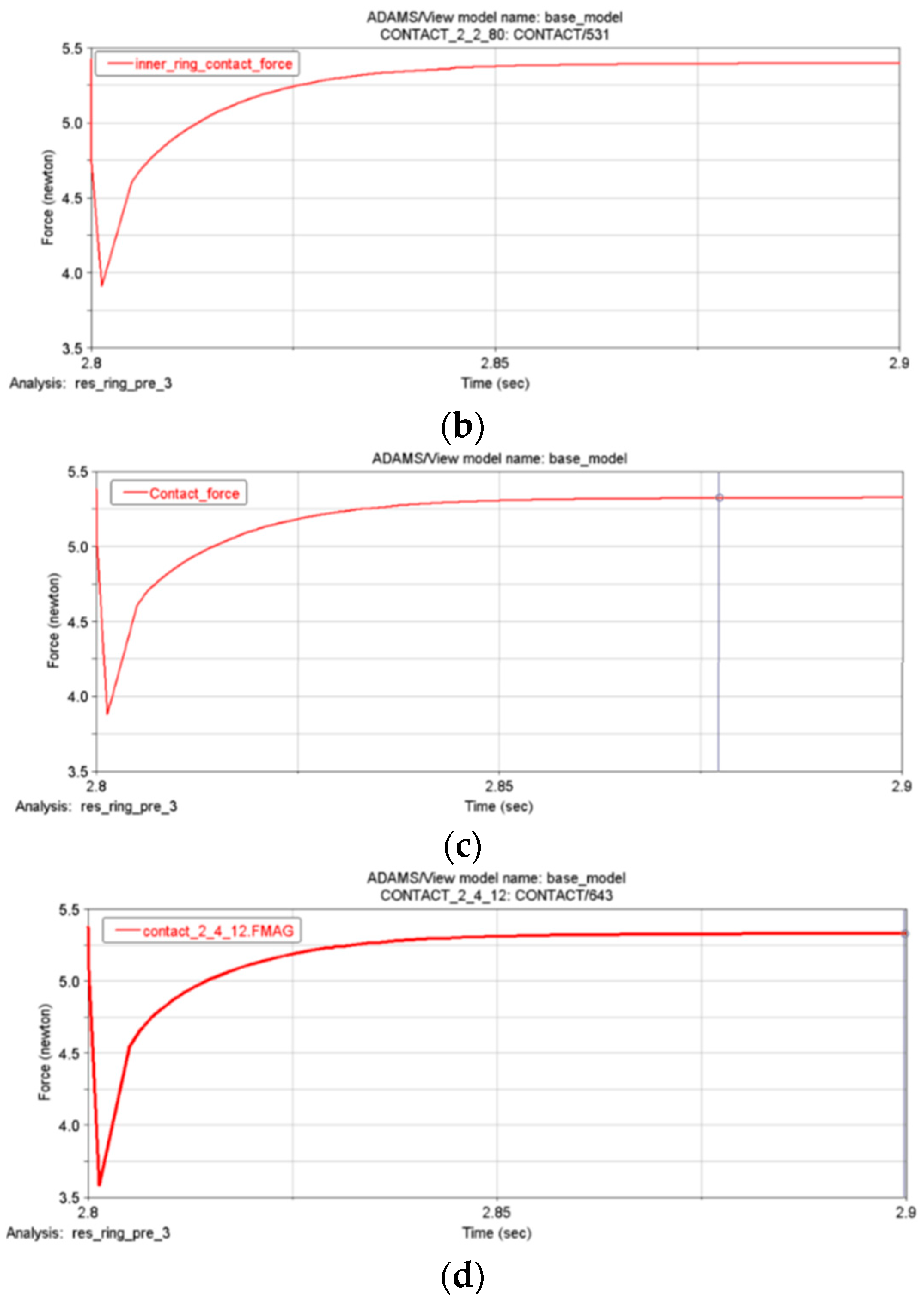
Figure 18.
Relationship between idler gear size and contact pressure of flexible ring (radius of idler gear 7.0 mm). (a) Contact force between the flexible ring and outer ring; (b) Contact force between the flexible ring and inner ring; (c) Contact force between the flexible ring and left idler gear; (d) Contact force between the flexible ring and right idler gear.

Table 1.
Relationship between idler gear size and driving torque.
| Serial Number | Idler Gear Radius (mm) | Drive Torque (Nmm) |
|---|---|---|
| 1 | 7 | 33 |
| 2 | 7.2 | 124 |
| 3 | 7.5 | 364 |
Table 2.
Relationship between contact pressure and idler gear size.
| Serial Number | Idler Gear Radius (mm) | Contact Force of Idler Gear (N) |
|---|---|---|
| 1 | 7 | 2.4 |
| 2 | 7.2 | 5.3 |
| 3 | 7.5 | 9.1 |
Table 3.
Relation between flexible ring compression and driving torque and contact pressure.
| Serial Number | Radiusof Flexible Ring (mm) | Shrinkage of Flexible Ring (mm) | Drive Torque (Nmm) | Contact Pressure with Idler Gear (N) | Contact Pressure with Inner and Outer Rings (N) |
|---|---|---|---|---|---|
| 1 | 19.25 | 0.5 | 5.3 | 5.3 | 5.5 |
| 2 | 19.5 | 1 | 11 | 11 | 11 |
| 3 | 19.75 | 1.5 | 15.8 | 15.8 | 16 |
| 4 | 20.0 | 2.0 | 18.9 | 18.9 | 19 |
Disclaimer/Publisher’s Note: The statements, opinions and data contained in all publications are solely those of the individual author(s) and contributor(s) and not of MDPI and/or the editor(s). MDPI and/or the editor(s) disclaim responsibility for any injury to people or property resulting from any ideas, methods, instructions or products referred to in the content. |
© 2024 by the authors. Licensee MDPI, Basel, Switzerland. This article is an open access article distributed under the terms and conditions of the Creative Commons Attribution (CC BY) license (https://creativecommons.org/licenses/by/4.0/).
Share and Cite
MDPI and ACS Style
Wu, H.; Liu, C.; Qian, Z.; Kang, X.; Liu, H. Analysis of Kinematics and Dynamics of Rolling Ring Based on Finite Element Method. Electronics 2024, 13, 1235. https://doi.org/10.3390/electronics13071235
AMA Style
Wu H, Liu C, Qian Z, Kang X, Liu H. Analysis of Kinematics and Dynamics of Rolling Ring Based on Finite Element Method. Electronics. 2024; 13(7):1235. https://doi.org/10.3390/electronics13071235
Chicago/Turabian StyleWu, Haihong, Chengshan Liu, Zhiyuan Qian, Xiao Kang, and Huiqun Liu. 2024. "Analysis of Kinematics and Dynamics of Rolling Ring Based on Finite Element Method" Electronics 13, no. 7: 1235. https://doi.org/10.3390/electronics13071235
Note that from the first issue of 2016, this journal uses article numbers instead of page numbers. See further details here.