Abstract
Individual model verification is a common practice that increases the quality of design on the left side of the Vee model, often before costly builds and prototypes are implemented. However, verification that spans multiple models at higher levels of abstraction (e.g., subsystem, system, mission) is a complicated endeavor due to the federated nature of the data. This paper presents a tool-agnostic approach to higher-level verification tasks that incorporates tools from Semantic Web Technologies (SWTs) and graph theory more generally to enable a three-pronged verification approach to connected data. The methods presented herein use existing SWTs to characterize a verification approach using ontology-aligned data from both an open-world and closed-world perspective. General graph-based algorithms are then introduced to further explore structural aspects of portions of the graph. This verification approach enables a robust model-based verification on the left side of the Vee model to reduce risk and increase the visibility of the design and analysis work being performed by multidisciplinary teams.
1. Introduction
In systems engineering, a primary goal of system design and analysis is the view of the system as a whole—both the sum of its parts and the emergent properties that are seen at the system level. An important aspect of this effort is extensive verification and validation (V&V) that provides evidence that the design complies with the requirements (verification) at each level of abstraction (e.g., component, subsystem, system, mission) and that the compliant system satisfies the stakeholders needs and purposes (validation).
In the classic Vee model, V&V happens on the right side of the Vee model. In essence, this effort occurs in designed and built test subjects, whether components, subsystems, systems, etc. While it is true that this process is not entirely linear (early validation of the system or mission can begin before all lower-level designs have been completed and passed their own V&V phase), the bulk of V&V occurs after detailed design work at the respective level of abstraction has been completed and implemented.
At lower levels of abstraction, a different approach has evolved that allows for a good portion of V&V work to be performed on the left side of the Vee model through model-based engineering (MBE). In MBE, design and analysis models can be built to provide high levels of confidence that designs are meeting requirements before a prototype has been built.
This becomes murkier as design moves higher on the Vee model to the subsystem, system, and mission levels. These require a level of collaboration between models, which has seen more limited adoption, although it is gaining ground in research and industry practice [1,2,3]. Digital engineering (DE) is a common term for an umbrella domain whose objective is to “computationally integrate” the model-based systems engineering (MBSE) tools and concepts with each other and the digital models created in other engineering disciplines practicing MBE. According to the United States Defense Acquisition University (DAU) glossary, DE is “an integrated digital approach that uses authoritative sources of systems’ data and models as a continuum across disciplines to support lifecycle activities from concept through disposal [4]”. Implicit in this umbrella domain is the study of how to connect different digital models in a way that yields the greatest benefits—do digital models connect just to pass data between each other, or can they connect in a way that yields insights that are emergent at the system level?
One approach is at the tool level. For example, the Ansys ModelCenter product [1] provides a multi-domain, multi-model method for verification and analysis, but it is tied to a specific tool implementation. This requires a tool-to-tool integration that can be brittle in nature [5], and it ties system-level verification to a specific tool vendor. Another approach focuses on the MBSE model itself. An example is SAIC’s Digital Engineering Validation Tool [2], which provides a rules-based analysis to systems modeled in SysML. This approach is domain neutral (SysML models can describe multiple domains), but it is model dependent—the verification only analyzes a SysML model.
This leads to the research question examined in this paper: how can model verification be approached in a tool-agnostic manner that reaches across the DE ecosystem to produce model verification at higher levels of abstraction? This question requires a knowledge representation that allows models originating from different sources to be represented in a common manner that can then be reasoned on to perform the required verification tasks.
The research presented in this paper introduces a three-pronged methodological approach to verification that enables a multi-model view of the verification problem. It utilizes SWTs and graph theory to develop a robust, tool-agnostic representation of relevant system/mission data and applies Description Logic reasoning (using the Pellet reasoner), closed-world constraints (using the Shapes Constraint Language (SHACL)), and graph-based analysis to perform verification tasks. The results of the individual prongs are aggregated together to provide high-level model verification results across a broad range of requirement types. The research then implements this three-pronged approach to the verification of digital threads in a multi-model analysis setting. It provides assurance of the methodology through extensive testing of failure paths found in the requirements when applied to a catapult case study. This implementation of the methods presented demonstrates the capacity for an extensible analytic method for verification in the multi-model setting.
2. Background and Related Work
The research contribution presented in this paper builds on the literature related to graph-based knowledge representation as well as model verification, both in the SE context. While these fields are not entirely independent, they can be pursued separately and must be addressed separately. Thus, this section discusses the relevant literature from the SE discipline along three avenues: Semantic Web Technology, graph theory, and model verification. It then provides a brief overview of previously published research by the authors that forms the foundational framework that will be used and extended to address model verification using a suite of graph-based analyses.
2.1. Semantic Web Technologies
SWTs are a suite of technologies and a field of research centered around graph data structures and ontology. While many definitions of ontology have been developed, for purposes related to computational use in a systems engineering context, the definition from Wagner et al. is appropriate: “An ontology is a directed labeled graph that is identified by a unique IRI (Internationalized Resource Identifier) and that describes a set of things by a set of propositional statements that are regarded to be true in some context” [6].
The formal representation of knowledge and propositional statements of a computationally enabled ontology allow for reasoning using formal mathematical logic. This capability has been explored some in the systems engineering literature. Hennig et al. use the Unified Modeling Language (UML) to align system-related data to ontologies. They present several different reasoning tasks that can be performed once data has been aligned to ontologies, including the automatic creation of Critical Items Lists (CILs) and allocation of different subsystems to the various engineering disciplines responsible for some aspect of the design [7]. Eddy et al. use semantic rules in reasoning to generate potential designs from a data source for consideration by an engineering team [8]. The Ontology Modeling Language (OML) uses an ontology-backed modeling language to facilitate automated checks for satisfiability and consistency [6]. Yang et al. provide a rich review of ontologies in SE [9].
One proposed advantage in using ontologies for knowledge representation is to enable interoperability between different tools using the suite of underlying ontologies as the common vocabulary to transfer knowledge between various tool metamodels. This interoperability pursuit has been discussed in engineering research. NASA’s Jet Propulsion Lab (JPL) has developed the openCAESAR platform and OML to support interoperability between elements of a design process [5,6,10]. Moser’s Engineering Knowledge Base (EKB) also aims to use ontologies to provide interoperability in intelligent engineering applications (IEAs) [11].
While interoperability is a key theoretical advantage to the use of ontologies, in practice, ontologies have been plagued with interoperability concerns that stem from differing philosophical approaches to their development [12]. To help address this concern, ontologies are often developed across a spectrum of abstractions. Top-level ontologies (TLOs) are abstract ontologies meant to provide philosophical underpinning for lower-level ontologies. Examples include the Basic Formal Ontology [12] and the Unified Foundational Ontology [13]. While TLOs are often not directly applicable themselves, ontologies built from a common TLO foster interoperability among mid-level and domain ontologies [12]. Mid-level ontologies expand on a TLO to provide more structure to domain specialists in building their own domain ontologies. An example of a set of mid-level ontologies is the Common Core Ontologies [14], built using BFO. Domain ontologies describe domain-specific concepts. They are the level at which domain experts can be engaged to take the body of knowledge available in a given domain and translate it into ontological form. Application ontologies are specific to a given application. This may be an application in a software context, such as an ontology that describes the SysML descriptive modeling language [15].
SWTs allow explicit knowledge to be expanded via automated Description Logic (DL) inferencing based on knowledge captured in ontology terms in the form of logical expressions. This is undertaken using an open-world assumption (OWA), where information is not assumed to be complete. Thus, things like minimum cardinality are not directly assessable using SWT reasoners. Other SWT tools such as the Shapes Constraint Language (SHACL) permit closed-world rules to be executed against ontology-tagged graphs.
2.2. Graph Theory
Ontologies provide a markup language for graphs of data, making them specialized forms of a more general graph structure. Graphs are characterized by nodes and edges that connect the nodes. In its most basic form, a graph’s edges are bidirectional, but a directed edge can be introduced to make the graph a directed graph, or digraph. Further, edges can be labeled to specify things like the relationship the edge represents. Thus, an ontology is a “directed, labeled graph” [6].
Graph data representations are studied in the mathematical field of graph theory and have been used to perform analysis and design algorithms for solving problems such as the traveling salesman problem, shortest path problems, and network topology [16]. Graph representation within the systems engineering domain has seen broader inquiry and application beyond ontology-aligned graph representation.
Medvedev et al. transformed an OPM model to a directed graph representation using the Neo4j graph data store [17]. Using this graph representation, they were able to perform several analyses on the graph representation of the system, including longest/shortest path calculations, centrality metrics (including PageRank and Eigenvector centrality), and neighborhood queries [17]. Cotter et al. [18] analyzed SysML models through graph representations of the models to analyze relationships between entities using this representation to automatically detect different architecture patterns being used in the SysML models [18]. Mordecai et al. [19] looked at using mathematical category theory and graph data structures in their approach. This structure allows for tool-agnostic representation of data that can be transformed in various ways to provide reporting and analysis value. Herzig et al. use a graph-centric pattern-matching approach to detect inconsistencies between multiple viewpoints defined in SysML models [20].
2.3. Verification Tasks
Madni and Sievers delineate between traditional system verification, which answers the question “Does the design meet the requirements?”, and model verification, which answers the question “Is the model trustworthy?” [3]. They elaborate on this by noting that verification should assess that a “model is sufficiently accurate to trust its predictions” [3]. This could be reframed as a model’s adherence to its own set of requirements. According to NASA’s Handbook for Models and Simulation, model verification is “the process of determining the extent to which [a model or simulation] is compliant with its requirements and specifications as detailed in its conceptual models, mathematical models, or other constructs” [21]. This is separate from model validation, which also plays a part in the trustworthiness of the model. Madni and Sievers describe model validation as answering the question “Does the model accurately describe the system?” [3]. NASA similarly defines model validation as “the process of determining the degree to which a model or a simulation is an accurate representation of the real world from the perspective of the intended uses of the [models and simulations]…” [21].
Model verification allows movement of portions of the verification task to the left side of the traditional systems Vee model for earlier verification. Madni and Sievers discuss five different approaches to model verification: “Model Appraisal; Guided Modeling, Simulation; Formal Proof; and Digital Twin and Digital Thread” [3]. Their category of formal proof includes formal logic to assess model trustworthiness. Chapurlat et al. and Nastov et al. [22,23] give similar approaches to model verification. Chapurlat et al. [24] propose the executable, verifiable, and interoperable Domain-Specific Modeling Language (xviDSML) and formal approaches to enable model verification. This approach of using a modeling language that addresses verification within its syntax as a primary modeling language in design can be compared to research at NASA’s Jet Propulsion Lab (JPL) using the Ontological Modeling Language (OML) as a primary modeling language to describe systems in a verifiable way [5,6,10].
The overall approaches cited by Madni and Sievers and Chapurlat et al. can be used to perform model verification based on model requirements in multiple contexts, including models of the system under design as well as models of the analysis system being used in the design process. Additionally, model verification could refer to application-specific requirements, such as a model’s adherence to a specific design methodology such as the object-oriented systems engineering method (OOSEM) [25].
Rodano and Giammarco looked at verification of well-formed system architectures and verified the architectures based on a list of axioms [26]. While their lists are useful guides for developing verification rules for well-formedness questions in other contexts, another important contribution of their work is the recognition of the inherent flexibility needed in some verification tasks. Questions regarding the well-formed construction of a model will by nature vary depending on context.
In this paper, verification of model well-formedness is performed using a context-specific definition of well formed and an aggregation of deductive methods to check the structure of the model. It models verification in the context of an ontology-aligned representation of a model. Instead of adjusting the primary modeling language of the system under analysis, this research performs transformation from more traditional tooling to a verifiable representation (ontology-aligned data) using the mapping interface of DEFII. It focuses the use case on well-formed checks of a digital-thread system of analysis.
2.4. Digital Engineering Framework for Integration and Interoperability
The Digital Engineering Framework for Integration and Interoperability (DEFII) is an approach to DE using SWTs [27] (Figure 1). At its core, DEFII enables users to align system data to ontologies that provide formalized definitions of domain knowledge, mission data, etc. This alignment allows for a tool-agnostic authoritative source of truth (AST) that facilitates interoperability via exchanges of mission and system data. In the AST, information is stored in a triplestore that aligns individual parameters with ontologies. This enables a common data source approach to ensure information consistency. However, the alignment to ontologies and the graph-based representation of the data hold data in a form that can be mined for additional insights.
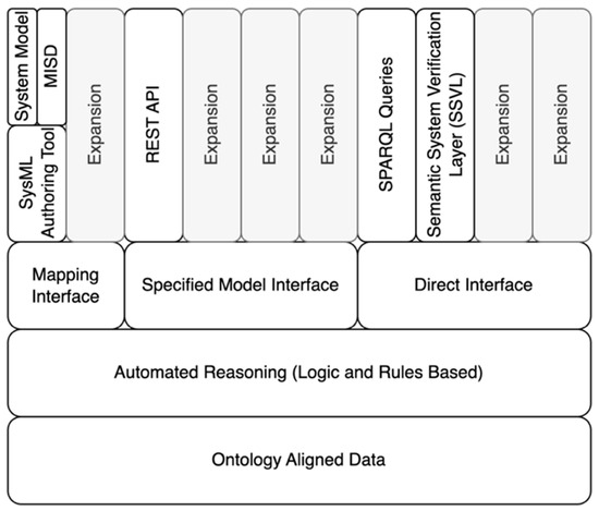
Figure 1.
Digital Engineering Framework for Integration and Interoperability—adapted from [27].
The DEFII framework affords three different types of interfaces: the Mapping Interface, the Specified Model Interface, and the Direct Interface.
The Mapping Interface takes a tool- or model-first perspective. Models being represented in SysML or another modeling language are parsed to determine ontologically relevant material captured by the model in a process called “mapping”. This parsing and mapping can be very tool specific, but it can conceptually refer to a broader modeling language or structured data. For example, mapping from a SysML model is often performed via explicit tagging of the model with stereotypes that correspond to classes in the ontology [27,28].
The Specified Model Interface takes an ontology-aligned data-first perspective. It exposes data to external tools in a specified way that enables tools to interact with the data without having knowledge of the underlying ontologies. The interface is specified through the use of a Model Interface Specification Diagram (MISD) [27], typically defined in SysML. This interface references the ontology-aligned data and presents the data in a tool-agnostic, ontologically unaware format to be read and written to by various tools.
The Direct Interface uses SWT tools to directly access the ontology-aligned data. Tools like the SPARQL Protocol and RDF Query Language (SPARQL) [29] queries and Shapes Constraint Language (SHACL) [30] shapes use the Direct Interface. This interface can be compared to a data analyst using the Structured Query Language (SQL) to query databases directly. The ability to interact with specificity enables unique opportunities to analyze and manipulate the data.
3. Methods
3.1. Semantic System Verification Layer
DEFII is intended to enable expansion across each interface. One such expansion is the introduction of the System Semantic Verification Layer (SSVL) [31], as shown in Figure 1. This verification layer uses a direct interface into the ontology-aligned data to perform various verification tasks. To date, SHACL has been used to test for regular expressions and existence [31] and SPARQL has been used to test for various open- and closed-world rules based on a limited completeness definition [32]. The SSVL has been extended considerably in the methods of the research presented.
3.2. Extend SSVL to Apply Three-Pronged Verification Approach
Once the system under analysis has been properly defined, the verification layer itself can be applied. The SSVL enables direct interaction with the ontology-aligned data using different tools to implement open- and closed-world reasoning. Three broad approaches are used in the proposed SSVL: Description Logic reasoning, SHACL constraints, and graph-based algorithms (Table 1).

Table 1.
Example requirements categorized by verification prong.
3.2.1. Description Logic Reasoning
DL reasoning is the first prong of the verification layer. Ontology-aligned data should be internally consistent. Given a robust ontology definition, many different types of verification tasks can be performed in this framework.
Requirement 1 in Table 1 shows a DL-reasoning task. DL reasoning permits evaluation of two variable logical expressions subject to an OWA. In Requirement 1, maximum cardinality is identified as a constraint. An ontology might define a restriction on Class A such that “Class A hasAttribute max 1 Class B”. This restriction will allow a DL reasoner to check for consistency in the instance data aligned to the ontology definitions. An inconsistency will be detected if Class A is connected to more than one instance of Class B via the object property hasAttribute.
3.2.2. Closed-World Constraint Analysis
The second prong of verification uses SHACL to analyze the same dataset. While DL reasoning is a powerful tool for consistency checks and the creation of logical entailments, it is limited in analysis due to the OWA. Questions of existence or minimum cardinality are typically unanswerable using DL reasoning with an OWA. SHACL uses “shapes” to identify nodes within larger graph patterns that are evaluated against some constraint. More complex checks are achieved using advanced features [33] such as SHACL SPARQL, which enables custom constraints provided as SPARQL queries instead of using built-in constraint types.
Requirement 2 in Table 1 is a minimum cardinality restriction of the form Class C hasAttribute min 1 Class D. Since missing relations are not assumed to be non-existent under the OWA, reasoning under a CWA is needed. A SHACL shape can express restrictions such as that of Requirement 2. The full verification suite will often include many shapes.
3.2.3. Graph-Based Analysis
Graph-based analysis is the third prong of the verification layer. While graph-based analysis is not specific to SWT, a range of analyses are enabled if the data can be assessed in a pure graph format. Flattening the multi-digraph ontology-aligned data into a simpler directed graph where all edges denote the same or similar relationships allows for these types of analyses.
For Requirement 3 in Table 1, a SPARQL query that pulls all nodes with the hasPart composition relationship could result in the creation of a subgraph that only displays the portions of the ontology-aligned data related to composition. This could then be assessed to determine if it is weakly connected. A series of subgraphs across a series of relationships (sequence, composition, etc.) could be created to verify many aspects of the ontology-aligned data’s structure.
A SPARQL query can be used to construct a subgraph that looks at specific object properties. Using the NetworkX Python library [34], a simple digraph can be created using ordered pairs. More complicated queries can add additional details to the graph, such as node and edge labels or edge weights. These can be ingested during graph creation, and the NetworkX library can be used to perform additional graph-based analyses. For large graphs that need a defined structure, general graph algorithms are well suited for analysis.
3.2.4. Update/Develop Ontologies to Align with Verification Tasks
The DEFII framework centers around ontology-aligned data. The SSVL accesses ontology-aligned data via the Direct Interface provided by the DEFII framework. Thus, proper ontological definitions and alignment to those definitions is a preliminary step to performing the verification. Depending on the verification definition developed above, this may require development of a completely new ontology. However, if the verification needs are primarily domain focused, an existing domain ontology may provide adequate coverage already or only need to be expanded to accommodate the particular verification tasks identified.
3.2.5. Update Mapping to Accommodate Ontologies as Needed
Depending on the context, existing mapping may need to be updated to enable mapping to the ontologies created or updated in this method. In previous research [27], mapping is specific to the Cameo tool suite for SysML models annotated with Basic Formal Ontology (BFO)-conformant ontology terms. The mapping is thus specific to Cameo’s implementation of the SysML language, and it also ignores parts of the SysML structure that do not aid in domain understanding of the system under design or analysis. Mapping from a different tool or to capture aspects outside of the domain representations currently used requires additional effort.
3.2.6. Aggregate Analyses to Form Top-Level Verification
Once the above steps are complete, the three-pronged verification approach can be implemented. The results aggregated together produce a top-level result, where failure (denoted as the numeric 1) of any prong results in a failure of the general verification task:
Note that inconsistent ontologies that produce errors in the DL-reasoning prong of the approach may have downstream effects as other analyses may depend on logical entailments produced by reasoning.
This method is recursive and iterative. While ontology development was included as a subsection of the DL-reasoning prong, ontology development is needed to perform all three prongs of the verification task as they all use ontology-aligned data. Additionally, some forms of reasoning may be used to simplify and generalize the verification tasks. For example, in an aircraft design, a verification rule may require that the aircraft have landing gear. However, the ontology may have many different types of landing gear identified as subclasses of a more general landing gear class. Using taxonomical reasoning, any instance of a subclass of landing gear could automatically be classified as the more general landing gear, so a verification rule could be written at a higher level of abstraction to cover all landing gear types without specifying each type.
3.3. Verify Extended SSVL Approach
To verify the extended SSVL approach, a systematic test of the requirements defined above is needed. In previous research [32], four rules were defined in an abbreviated definition of a complete digital thread. In that example, faults were seeded in a manually verified model under test to verify each fault could be recognized independently and in combination with the other faults (16 tests total). The method presented here builds on this approach but modifies it in two important ways.
First, it is often the case that the rules identified can be violated in multiple ways. For example, a constraint that says a particular instance must have exactly two of a particular property can be violated by having less than two or more than two. Thus, rules must be further analyzed to determine all potential failure paths. Initial verification of the method should consider all failure paths.
Second, while four rules are useful for demonstration purposes, it is likely that a verification suite being used in practice will have far more than four rules. For example, in the results below, 26 failure paths are identified. This results in 67,108,864 (226) potential combinations for single failures of each failure path. SAIC’s Digital Validation Tool for SysML model validation contains 224 rules, or 2.7 × 1067 potential failure combinations [2]. This presents a combinatorial problem. An exhaustive test of all combinations becomes infeasible. To provide confidence in verification capabilities, a three-part test is presented:
- Mapped-Graph Single Failure—This result aims to test each failure path in isolation from beginning to end. This means that, where possible, faults are seeded directly into the tool where they are expected to originate. This process tests both recognition of the failure path and the mapping process for translating the model with seeded fault into the ontology-aligned data.
- Generated-Graph Single Failure—This result aims to test that a programmatically generated graph produces results in line with a fully mapped graph. A base case (no faults) generated from the standard mapping procedure can be used as a starting point. Additional graphs can be generated to seed the base graph with the identified faults associated with each failure path. These results can then be compared to the results from the Mapped-Graph Single Failure results.
- Generated-Graph Random Failure Selection—This result aims to test random combinations of the seeded faults to ensure that multiple failures can be detected. It uses the base mapped graph and the methods used for seeding individual faults used in Step 2 and combines these with a random number generator to generate random combinations of the seeded failure. The random number is represented in binary with the number of digits determined by the number of failure paths identified (a 1 in the corresponding digit denotes that a particular failure path should be inserted). Further filtering for mutually exclusive failures may be needed depending on the context. These randomly generated failure graphs can then be used to test the verification suite to detect if the results produced are expected based on the failure of each individual fault.
While this portion of the methods will be repeated as the verification suite is expanded or applied to different verification requirements, it will not be needed for each system or mission to which the expanded SSVL is applied. Verification suites can be built and verified themselves separately from individual projects and system efforts. Where they will need to be re-verified based on an extension of modification of the definition will probably begin as a heuristic, experience-based judgement to begin while additional research considers this question.
3.3.1. Application Context—Digital Thread
The methods presented in this paper are theoretically applicable across many different verification contexts. To provide initial verification of the methods, these results apply the methods to a digital-thread application context. In this context, the methods are used to provide model verification for a multi-model analysis in a catapult case study.
3.3.2. Definition of System of Analysis in the DEFII Framework Context
The digital thread is a key DE concept. While the precise definition of the digital thread is debated in the literature [35], in general, the digital thread looks to connect various models from across domains to a central design or analysis regimen designed to achieve certain objectives. DAU defines the digital thread as “An extensible, configurable and component enterprise-level analytical framework that seamlessly expedites the controlled interplay of authoritative technical data, software, information, and knowledge in the enterprise data-information-knowledge systems, based on the Digital System Model template, to inform decision makers throughout a system’s life cycle by providing the capability to access, integrate and transform disparate data into actionable information” [4]. The concept of the system of analysis (SoA) can be considered a subtype of the digital thread and refers to an analyzing system that can be scoped across multiple levels of abstraction (mission, system, subsystem, etc.) and where results from multiple models can be used to arrive at the analysis objectives of the SoA itself. A simple SoA could be a linear system, where each analysis feeds the next analysis, with the final result being the analysis objectives (Figure 2).
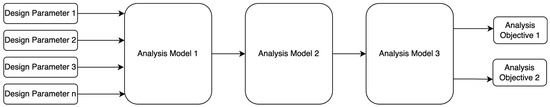
Figure 2.
Basic, linear system of analysis.
However, Figure 3 shows a slightly more complicated example of an SoA. Models 1 and 2 independently feed Model 3. Model 1 also produces a top-level analysis objective, but the other two analysis objectives are produced by Model 3. Here, the sequencing of models is important, and changes to Model 1 necessitate a rerun of Model 3. As SoAs become more complicated, the directed graphs that represent the individual parameters, inputs, and outputs of the various models become more complicated. This makes visual, manual “checking” of the construction more difficult and prone to error.
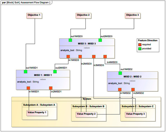
Figure 3.
Abstract SoA with parallel and series components (adapted from [32]).
The SoA as constructed here is used by the DEFII framework to produce a model interface that allows for each model represented in the diagram to be presented via REST API from which external tools can access and manipulate data. This aggregation of multiple models to show how the system under analysis and intermediate models interact with each other to produce high level analysis objectives is referred to as the assessment flow diagram (AFD) and is based on Cilli’s work on the integrated systems engineering decision management (ISEDM) approach to trade studies [36]. Implementation of this method places some requirements on how the digital thread is formed. Further, the DEFII framework has some requirements for accurately producing the interface, including proper alignment of the model to BFO [12] and Common Core Ontologies (CCOs) [14], which are compliant ontologies to describe domain details.
Verification related to the construction of the SoA is an appropriate test of the methods presented in this paper. The structure of an SoA can be clearly defined and articulated and provides opportunities to test each prong of the expanded SSVL. Applying the methods to the SoA construction not only verifies the methods but also produces artifacts that will be useful for future research and application to industry by providing a way to check the SoAs that are currently being used and those that will be created in the future.
3.3.3. Establish Definition of Verification Task—Well-Formed Construction of an SoA
The first step to expanding the SSVL to verify the well-formed construction of the SoA is to clearly define what a well-formed SoA is. The requirements for well-formed SoAs can be divided into the following categories:
- Allowed Connection—these requirements specifically look at how the SoA is connected. This includes how the system under analysis is connected, how different models are connected to each other, etc. Since connections are what make the edge aspects of the network, these requirements are important.
- Specification Requirements—these requirements describe things that should exist as part of a well-formed SoA.
- DEFII Requirements—these requirements are specific to an SoA as implemented using the DEFII framework. Generally, they will refer to ways that the SysML model should be configured in order for the expected mapping to align the ontology data.
- Graph-Based Requirements—these requirements are specific to a graph-based analysis of a subgraph of the ontology-aligned data.
Consider the following ten requirements (Table 2).
Table 2.
Requirement list for well-formed system of analysis.
In addition to category, each requirement is divided into assessment approach and context dependence. The assessment approach is a classification step to clarify where the verification task will be performed. Context dependence is an extra classifier that acknowledges that an application context needs flexibility to adapt to different use cases, organizations, etc.
3.3.4. Develop the SoA Ontology
Ontology development occurs across different levels of abstractions, from TLOs that provide philosophical underpinning to a suite of ontologies to promote interoperability to application ontologies that are used for specific tasks but may not be tied to any TLO. The SoA ontology is an ideal candidate for development as an application ontology. The SoA ontology can be used across domains to describe a particular application (SoA verification). As such, an SoA ontology’s tags need not follow a TLO’s rigid guidelines regarding definition and inheritance as they are not meant to promote inoperability. Moreover, the use of the application ontology creates a more lightweight solution, which results in a more limited subset of data to be used for reasoning tasks. This is advantageous from a computing perspective as higher levels of reasoning can be applied without overtaxing computational resources.
The SoA ontology was built based on the axioms and types needed to describe the abstract SoA (Figure 3) and DEFII ontology term-tagging requirements (in SysML using the stereotype feature) using terms from a reference ontology. There are several elements to consider:
- System Under Analysis Value Properties (SuAVP)—these are base elements that will be manipulated by the SoA. They represent relevant system, mission, environment, etc. parameters. In DEFII, these value properties must be tagged with a class from a top, mid-, or domain ontology.
- Models—these models are the intermediate simulations, analysis models, etc., that are used in the SoA to characterize the system under analysis. The models include inputs and outputs. In DEFII, these models must be tagged to identify them as models in this context.
- Analysis Objectives—these are the objectives of the SoA. They can be included in the mission, system, etc., architecture, or they could be defined at the analysis level as external values that are being analyzed. In DEFII, these objectives must be tagged with a class from a top, mid-, or domain ontology.
- Connectors—these are connections between the relevant items to define the graph of the SoA. They show how the intermediate models connect to each other and how they relate to the system under analysis and the analysis objectives. In SysML, these are represented as binding connectors in a parametric diagram.
There are a few other elements not readily apparent on the parametric diagram in Figure 3 that nonetheless need to be captured in the ontology definition.
- System Blocks—the system architecture uses composition relationships between blocks to show the architectural hierarchy. While this is not necessarily explicitly displayed in the parametric diagram, these describe the relation between SuAVPs and the system. In DEFII, these objectives must be tagged with a class from a top, mid-, or domain ontology.
- High-Level Analysis Block—DEFII requires the definition of a high-level “Act of Analysis” to aggregate the models and systems associated with any given analysis. In SysML, this is a block (an example can be seen in Figure 11).
Given the elements shown above, a rough outline of the ontological terms can be created (Figure 4). Protégé [37] was used to develop the ontology.
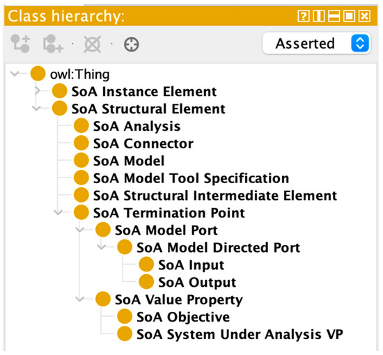
Figure 4.
Taxonomy of SoA structural elements.
Intermediate elements refer to things not explicitly captured in the SoA, such as blocks of a system architecture, that need to be evaluated to determine well-formedness. Ports are subclassed by directed ports according to Requirement 9, which states that a port must include direction (implying that a check for undirected ports needs to result in an ill-formed result).
Two primary classes were chosen: the SoA Structural Element and SoA Instance Element. These correspond to SysML’s definitional components (e.g., blocks, value properties, etc.) and instances of those definitional components, respectively. Within the semantic layer, these classes tag sets of named individuals related by an SoA_is_related_to object property (Figure 5).
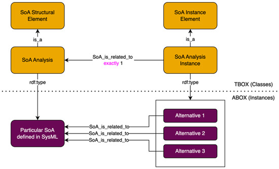
Figure 5.
Relationships between structural and instance elements.
Beyond the class names and taxonomy, additional relations can be added to provide for a richer ontology capable of reasoning and expanding the knowledge base. For example, cardinality can be established to check for aspects of Requirement 1: an SoA Connector can connect to a maximum of one input, output, SuAVP, and objective. Likewise, Requirement 3 specifies that the connector have exactly two termination points (min and max cardinality set to two). Declaring object properties as functional allows for limits related to cardinality. For example, the SoA_terminated_to_source object property requires that it can only be used once per connector—if a connector has two “sources,” this should be considered an inconsistent result. Composition can also be captured in the definition (Figure 6).
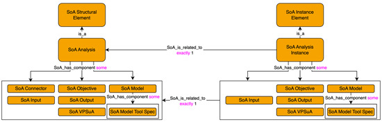
Figure 6.
Relations between SoA structural and SoA instance elements.
The SoA instance element class and subclasses mirror the SoA structural element class and subclasses in most respects. SoA Connectors do not need to be instantiated—they are only on the definition side. Additionally, the SoA_is_related_to object property relates each instance to its corresponding structural element. This object property is symmetric in that the relationship goes both directions. However, structural elements can have this relationship with many different instances, but instance elements can have this relationship with only one structural element. Additional details on ontology creation can be found in Appendix A.
3.3.5. Update Mapping to Incorporate New Aspects Introduced in Ontology Development
With a base SoA ontology created, a mapping update is needed to extract SoA information from the model. In DEFII, the SysML stereotype is used to explicitly identify the terms in the SysML model that are related to ontology terms.
Since the mapping of the SoA is meant to be sparse and map only elements related to the SoA application ontologies, an element’s relationship to the domain ontologies is not explicitly mapped into the ontology-aligned data. However, there is a need to verify that some elements that are part of the SoA have a domain ontology term to which they align (e.g., Requirement 7). To accomplish this, the mapping process examines the terms that are part of the SoA and checks that they have a corresponding term in the relevant BFO compliant ontologies. The results of this check are stored as SoA_exists data properties; if there is a corresponding ontology term, the SoA_exists property is true for the element. This allows for verification that elements are properly tagged for later mapping to the domain ontology for use in the broader DEFII framework.
3.3.6. DL Reasoning
Where possible, DL reasoning using the Pellet reasoner [38] was used to implement rules. As these are based off the mapping extensions and ontology definition, no additional development was needed.
3.3.7. Develop SoA Constraint Analysis
As many of the requirements listed in Table 2 specify constraints about existence, they are evaluated using SHACL’s closed-world construct. SHACL constraints are written as shapes that specify the pattern that needs to be checked. Figure 7 shows a simple SHACL shape that checks for the existence of an SoA Analysis Instance (Requirement 8). The “targetNode” designator allows for the shape to apply the constraint listed on all instances of a particular class—in this case, the SoA Analysis Instance class. Thus, a series of shapes can be built to address closed-world reasoning concerns.
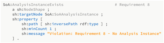
Figure 7.
SHACL shape for Requirement 8.
Constraints for more specific requirements were targeted using SHACL SPARQL (Figure 8). For example, the SSVL verifies that SuAVP is properly instantiated by using SPARQL to formulate a query confirming a node’s existence in relation to other elements in the model.
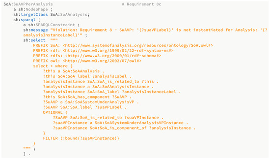
Figure 8.
SHACL shape using SHACL SPARQL constraints for a portion of Requirement 8.
SHACL support was added to DEFII using the library pySHACL [39] in Python. This also allows for custom results messages that can be dynamically created based on variable names from the SPARQL query, providing a useful means to troubleshoot an ill-formed SoA.
3.3.8. Develop Subgraph Generation and Analysis
The SoA use case also requires graph-based analysis. A simple example of a graph-based analysis is the detection of cycles in a directed graph. While it may be possible to construct a SPARQL ASK query to determine in pure SWTs whether there were cycles in an SoA, graph-based analysis provides a more general solution for assessing the graph. This is especially true since the transformation from ontology-aligned data to a simple digraph is both a simple procedure and a useful transformation to have for many future analyses unrelated to well-formed construction checks, such as impact analysis.
To look for sequencing, the current approach uses the SoA_terminates_toward and SoA_informs object properties to establish the two different relationships that relate to sequencing in the ontology-aligned graph. Nodes connected by these properties were first extracted via SPARQL, resulting in an ordered list of nodes that was then transformed into digraphs and analyzed using the NetworkX [34] Python library (Figure 9).
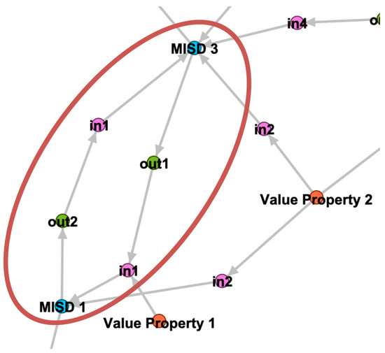
Figure 9.
Graph view of SoA (partial) with a cycle detected.
3.4. Apply SoA Analysis to Catapult Case Study
While the requirements and verification suite were developed using a simple, abstract SoA, a more complex, domain-based case study provides more insight into the capabilities provided by the approach and provides better assessment of the methods presented. A mechanical catapult system, which is a capability of a larger mission environment, was chosen as the application domain for demonstrating results [40] (Figure 10).
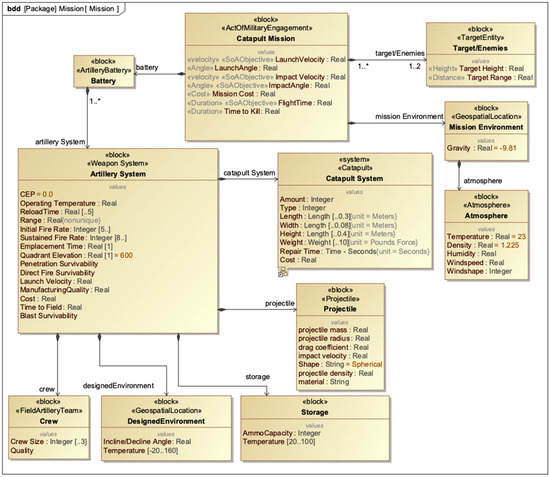
Figure 10.
Mission architecture of catapult case study—adapted from [40].
In the mission and system architecture, five analysis objectives were chosen:
- Impact Angle;
- Flight Time;
- Circular Error Probable (CEP);
- Range;
- Impact Velocity.
To determine the values for these five analysis objectives, a series of intermediate models are used. A geometry model that uses commercial CREO CAD software provides geometry information for various designs. A Fire Simulation model developed in MATLAB simulates the firing of the catapult. Multiple error models developed in Python provide error analyses. The application of these models to a top-level analysis block and the system under analysis is shown in the SoA bdd (Figure 11).
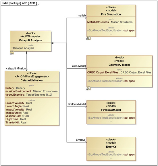
Figure 11.
System of analysis definition for catapult case study—adapted from [40].
The connections between the models, system under analysis, and analysis objectives are shown in a parametric diagram representation of the AFD (Figure 12). The AFD gives specific details on how the models are connected to each other and has implicit sequencing information in it.
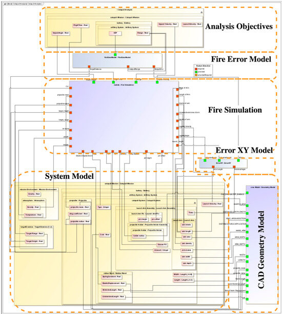
Figure 12.
Annotated assessment flow diagram for catapult case study—adapted from [40].
In this example, there are several layers of abstraction (mission, system, subsystem, etc.) visible and value properties from multiple levels of abstraction inform the AFD. The commercial CAD software model provides many of the base design parameters that have been characterized in the SysML model, and the simulation and error analysis models transform those base design parameters into the higher-level analysis objectives. The model graph is not too complex that observation of the AFD cannot easily yield the correct sequencing of model runs, but there are enough connections and relations to communicate the complicated nature that higher levels of multidisciplinary analysis require.
4. Results
Verification of the catapult case study begins with a manually verified SoA. In this base case (C0), all tests pass, and the SoA is declared well formed according to the definition detailed above. To verify that faults can be detected, faults can be systematically seeded into the base case to verify the pattern can be identified. However, as noted in the Methods section, each requirement must be analyzed to determine the different failure paths that could result in a failure of the requirement. For example, Requirement 1 states that like components cannot be connected. However, this requirement can be violated in multiple ways—an output can connect to an output, an input can connect to an input, etc. Thus, the requirements were expanded to identify each type of violation encompassed by a requirement, which resulted in 26 unique failure paths (Table 3). These are used to create initial test cases.
Table 3.
Expanded requirement list.
While each requirement is independent, there are several test cases that will produce failures in multiple ways. For example, the test that an output of a model cannot connect to an input of the same model can be detected by open-world reasoning, closed-world reasoning, and graph analysis.
4.1. Open-World Reasoning Result
Test Case C10 states that an input of one model cannot connect to another input of the same model. This is one of the ways that a model can connect to itself. Figure 13 shows a partial parametric diagram with the seeded fault. Table 4 provides the results from the three-pronged analysis. This test case only fails DL reasoning and passes the closed-world and graph analyses used in this research. A message is provided to guide the modeler toward the inconsistent elements that need to be resolved.
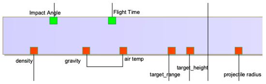
Figure 13.
Partial SysML parametric diagram showing seeded fault for Test Case C10.
Table 4.
Results for C10 showing inconsistency discovered through DL reasoning.
The Pellet reasoner’s explanation shows that the SoA_terminated_to_target object property is a functional property. Yet, the object property is used twice for element “09de70c2-0dfd-4599-8ebe-1dfaab9b7d61_SoA.” This results in an inconsistency in the ontology.
Note that while a SHACL constraint could be defined to catch this failure, the authors consider it best practice to apply restrictions in DL reasoning where possible. Robust ontological definitions have reuse value outside of this verification task by enabling better reasoning capability that can be used elsewhere. Thus, creation of a constraint within the ontology definition is often the better option when available for reusability and maintainability.
4.2. Closed-World Reasoning Result
Test Case C16 states that an SoA Objective must be tagged with an ontology term beyond the SoAObjective tag (which is only an application ontology term). This is a question of existence that requires a closed-world reasoning approach to answer. Figure 14 shows the specification for the objective in question, which has the domain ontology term CircularErrorProbability removed. Table 5 shows the results of the three analyses.
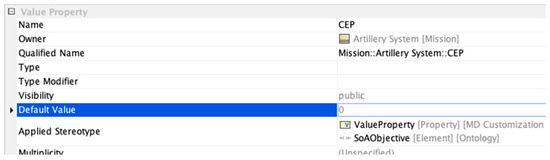
Figure 14.
Specification for CEP value property with missing stereotype.
Table 5.
Results for C16 showing SHACL violation.
The SHACL message uses variables captured in the SPARQL-based constraint to construct a descriptive message that enables quick navigation of the model to correct the defect.
4.3. Graph-Based Analysis Result
C25 and C26 are both specifically tied to the graph-based Requirement 10, which states that the SoA must be a DAG. Figure 15 shows a portion of a traditional directed graph view (created using GEPHI [41]) of the SoA with the detected cycle annotated. This cycle was created in C26. It is not a violation for an output port to be used to inform an SuAVP. Likewise, it is not a violation for that same SuAVP to act as an input to a model. Both of these are performed with the geometry model and represent clear use cases for design tasks in a multidisciplinary design project. However, the cycle is created by allowing the SuAVP that is written to feedback into a model that eventually affects the model that created this output.
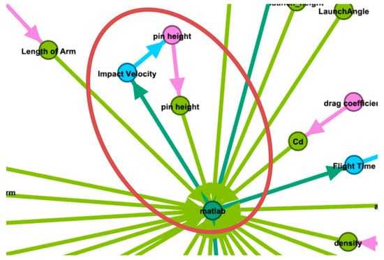
Figure 15.
Cycle created in C26.
4.4. Mapped and Generated Single-Test Results
The first two tests involve mapped and generated single-test results. Mapping occurred from variations on the base, manually verified test case (C0). Generated results began with this same base case but programmatically inserted failures to the graph. RDFLib [42] was used to interact with the graphs in python.
Table 6 shows the Mapped Results and the Generated Single Failure results. Top-level results match between the two. At the individual prong level, C1 and C2 show differences in the graph-based analysis. This can be attributed to the inconsistency of the ontology. In the Mapped Results, graph generation was built on an inconsistent ontology that still contained entailments, which enabled a cycle to be created and detected. In the generated results, the underlying graph was slightly different, so the reasoned graph did not produce a cycle. This reveals an important principle that inconsistent ontologies may produce errors downstream.
Table 6.
Mapped-graph vs. generated-graph single results.
Additionally, C3, C4, C5, and C7 were only built using the generated approach. These represent failures that would more likely be created with a mapping error than with a SysML modeling issue. For example, C7 checks for an SoA connected with three terminals. This is not possible in Cameo’s SysML authoring suite—a SysML binding connector can only connect to two points. However, it is possible for an error in mapping or an SoA generated from a source different than SysML to produce an SoA connector with more than two terminals.
4.5. Generated-Graph Random Failure Test Results
While the previous two tests looked at each fault in isolation, the third test checks for combinations of patterns to build trust in the results. One hundred additional test cases were generated at random. A random number represented in binary (26 digits) was generated, with 1 indicating that the corresponding failure be inserted and 0 indicating that the corresponding failure be omitted. For example, RTC1 seeds ten separate faults (C1, C4, C10, C12, C14, C15, C20, C24, C25, and C26). Additionally, mutually exclusive test cases were noted, and generated test cases were filtered to account for these limitations. For example, C3 and C12 require objectives and no objectives, respectively, so they are incompatible to be tested together.
Expected results are generated using OR logic between the individual results for each seeded defect (Table 7). The full 100 test cases passed with expected results (see Appendix B).
Table 7.
Abbreviated results from Generated-Graph Random Failure.
5. Discussion
Application of the expanded SSVL to a system of analysis shows correct operational results of the current SSVL implementation. Analyses using both SWTs and graph-based analysis are performed to provide model verification that accounts for multiple constraint types and perspectives on the model data. With the catapult and SoA analysis, this translates to higher confidence in construction of a particular type of digital thread (the SoA), which in turn builds confidence in the analysis objective results of the SoA. Further, application to two case studies (the abstract SoA and the catapult) emphasizes the flexibility of the method and the domain-neutral nature of the SoA analysis.
Additionally, the discovery of inconsistencies in the SoA’s construction can provide partial validation of the digital thread. An error in configuration may produce an inconsistent result related only to verification—the SoA was not built according to the model requirements. However, in a complex SoA, an inconsistency could be detected when each intermediate analysis team believes their analyses are “correct.” This result would still be a verification result—the SoA was not built according to the model requirements—but it would also yield a validation result that would promote discussion amongst the individual teams to determine how their analysis models interact and produce inconsistent results that may produce a model outcome that does not accurately represent the problem they are trying to solve.
During testing it was observed that inconsistencies caused by violations of rules and detected by the DL-reasoning prong may produce downstream effects. It is thus recommended that these issues be remediated prior to pursuing the next two prongs of the SSVL approach. Nonetheless, extensive testing shows top-level results using the three-pronged verification approach are effective. Errors seeded intentionally and programmatically were consistently detected. Further, the types of failures detected as patterns are not always readily assessed via manual inspection. For example, a cycle in a graph may be several layers deep, making visual inspection more difficult to perform. However, by transforming the SoA into a directed graph view based on sequencing information, a cycle could be detected using standard algorithms from graph theory for cycle detection.
Over the course of developing the ontologies, SHACL shapes, and graph analysis, several previous errors were also discovered in the catapult AFD, which has been used extensively for other research. One parameter had an incorrect stereotype that had never been noticed, and several parameters that were present but not used in various iterations of the model were not instantiated. Thus, even a well-established model was found to be ill formed. While the ill-formed nature of the model did not affect operation of the model in its given research context, ill-formed models can produce negative consequences that are not readily apparent, which underscores the value of developing methods for systematically checking models.
The methods are easily extended by enriching the ontology definition, adding shapes to identify additional constraints, and using more graph-based analyses. This extensibility provides flexible application of the methods and for effective customization to better fit specific systems, applications, organizations, etc.
Verification of the methods was performed using an SoA ontology and well-formedness definition and mapping from a SysML v1 model. However, the methods presented are tool-agnostic, which creates opportunity for expansion beyond SysML v1 as the generation point. For example, the additional test cases produced in the Results section were created using the Python library RDFLib [42]; while these were built using adaptations of the base case that was mapped from SysML, it would not be difficult to use a package like RDFLib to author completely original SoAs or make desired modifications to an existing SoA. Alternatively, SoAs could be defined in the new SysML v2 [43] and mapped to ontology-aligned data. The methods provide flexibility and extensibility.
5.1. Limitations
The results produced in this research are for a catapult model. Research sponsors provided the surrogate models used as intermediate analysis models in the digital thread. Because these models are surrogates to enable collaborative research in an open environment, the models have not been connected to real-world implementations of the systems designed. As the case study presented in this research focuses on model verification of the digital thread and not verification of the individual model analyses, the lack of hardware implementation is seen as reasonable. However, physical verification does reinforce trust in model verification, so this limitation is acknowledged.
Requirements used in the SoA use case are developed heuristically. Each requirement is included to address particular concerns or applications, but the developed requirements are limited in scope and should be seen as a starting point to tailor to a particular application or organization’s standard practices and may have gaps depending on the context.
The testing methodology chose one instance of each failure path to seed into the model being verified. Multiple instances of the same failure path in different parts of the model were not tested (due to combinatorial explosion). However, the implementation approach to verification along each prong of the SSVL is not expected to yield different results based on multiple instances of the same failure path.
As mentioned above, some SHACL constraints required SHACL SPARQL, an advanced SHACL feature [33]. Unfortunately, this advanced feature is not supported by as many tool vendors as the basic SHACL specification. However, pySHACL [39], an open-source SHACL validation engine connected to the popular open-source RDFlib Python library [42], has included the SPARQL advanced feature. Given the relatively small size of the SoA repository, using a third tool may be a viable option even if a different triplestore is used for primary operation.
5.2. Future Work
Verification of the methods was based on an SoA application ontology and a catapult analysis case study. Additional work to verify the methods in other settings, including domain verification and system/mission level requirements verification, is a potentially fruitful avenue of future research. While the methods will certainly work at other levels of abstraction, application to different types of verification tasks will surely be instructive to how to best use and potentially expand the methods to provide more robust verification functionality.
Even within the same use case, future research can yield new insights. Well-formed construction is a static query—was the SoA setup correctly? Given the graph-based view and the explicit connection to sequence in the definition of the SoA, dynamic queries on status of the SoA become apparent. For example, the SSVL might instead verify that the current state of the SoA is well formed or trustworthy. Additionally, there are elements of construction that do not necessarily need to depend on the system modeler. There may be ways to automate expansion according to an ontological definition of a context-dependent SoA that would enable the ontology to enrich the knowledge base further and reduce repeat work by human intervention, both increasing efficiency and reducing the risk of accidental error.
While graph-based assessments provide useful insight into the construction of the SoA, there is also a wealth of directions to bring the broader graph theory corpus of knowledge into the systems world through the representation used in this research. Critical path analysis across multiple edge weightings and automated runs of a multi-model digital thread are a few examples of research that could expand the representation.
The verification of the methods developed ways to automatically seed failures into an existing base graph to generate additional failure cases. Techniques built in this verification step could be extended to provide automated or assisted generation of graphs. For example, certain SoAs that are commonly used in an organization could serve as reference architectures in graph representation that could be programmatically customized to fit the current design space. Further research into the automated generation of graphs may also be worthwhile.
6. Conclusions
The research presented in this paper demonstrates a three-pronged analysis that uses graph approaches, including Semantic Web Technologies and broader graph theoretic algorithms, to assess ontology-aligned data. The methods presented are applied to verification of the construction of a particular form of the multi-model, multi-domain digital thread, termed the system of analysis. This verification of the SoA was then applied to a catapult case study to demonstrate how the general method presented in this research can be further refined to address specific use cases. Each prong of the analysis—open-world reasoning based on Description Logic, closed-world reasoning based on constraints defined in SHACL, and graph-based structural analysis—provides a portion of the verification task assessing the SoA as constructed. When the results are aggregated, a robust assessment of overall construction is delivered. These results provide a baseline that can be extended into a broader verification approach for multi-model system designs and analyses.
Author Contributions
Conceptualization, D.D. and M.B.; methodology, D.D., T.H. and M.B.; software, D.D. and T.H.; validation, D.D.; investigation, D.D., T.H. and M.B.; resources, M.B.; data curation, D.D.; writing—original draft preparation, D.D.; writing—review and editing, D.D., M.B., T.H. and D.V.; visualization, D.D., M.B. and T.H.; supervision, M.B. and D.V.; project administration, M.B. and D.D.; funding acquisition, M.B. All authors have read and agreed to the published version of the manuscript.
Funding
This research was funded by the Systems Engineering Research Center (SERC), a university-affiliated research center housed at Stevens Institute of Technology, under Grant W15QKN18D0040.
Data Availability Statement
Portions of the data presented in this study are available on request from the corresponding author. The data are not publicly available due to concerns with sponsor data.
Conflicts of Interest
The authors declare no conflicts of interest.
Appendix A. System of Analysis Ontology
The following system of analysis ontology is provided as a series of screenshots showing various aspects of the classes, object properties, data properties, and subclass axioms.
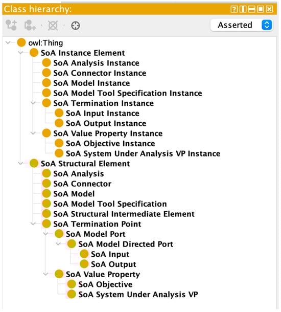
Figure A1.
Ontology Class Taxonomy.
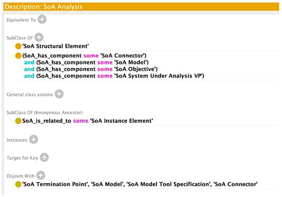
Figure A2.
Class Axioms for SoA Analysis.
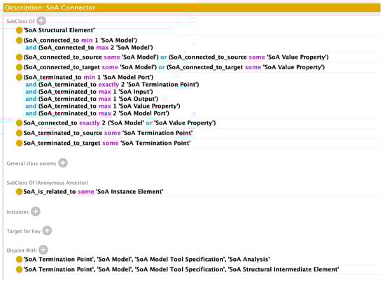
Figure A3.
Class Axioms for SoA Connector.
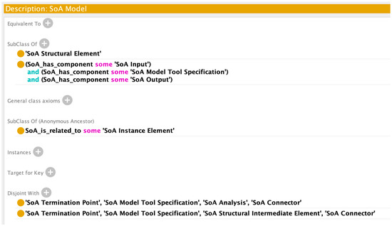
Figure A4.
Class Axioms for SoA Model.
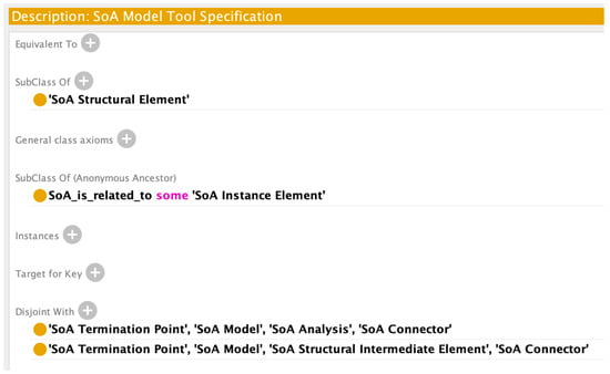
Figure A5.
Class Axioms for SoA Model Tool Specification.
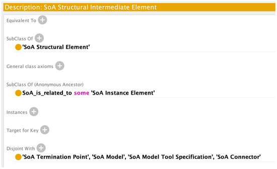
Figure A6.
Class Axioms for SoA Structural Intermediate Element.
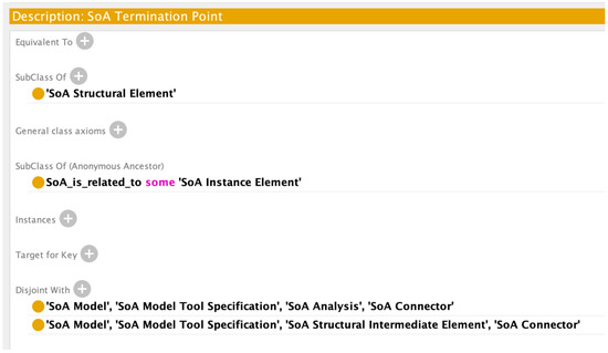
Figure A7.
Class Axioms for SoA Termination Point.
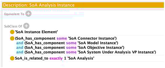
Figure A8.
Class Axioms for SoA Analysis Instance.
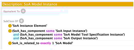
Figure A9.
Class Axioms for SoA Model Instance.
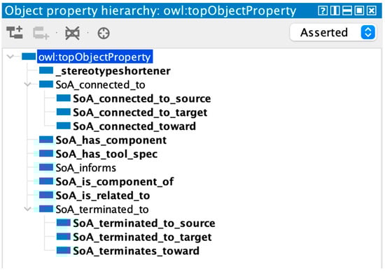
Figure A10.
Object Property Hierarchy.
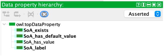
Figure A11.
Data Property Hierarchy.
Appendix B. Generated Test Case Full Results
Table A1.
Unabbreviated Results from Generated-Graph Random Failure.
Table A1.
Unabbreviated Results from Generated-Graph Random Failure.
| Scenario Name | Scenario Description | Expected Result | DL Reasoning | SHACL | GRAPH | Pass |
|---|---|---|---|---|---|---|
| RTC1 | 10101100000010011100111111 | [1, 1, 1] | 1 | 1 | 1 | TRUE |
| RTC2 | 01110000001010001011011111 | [1, 1, 1] | 1 | 1 | 1 | TRUE |
| RTC3 | 01100000001111000000110000 | [1, 1, 1] | 1 | 1 | 1 | TRUE |
| RTC4 | 00100001100110110110001011 | [1, 1, 1] | 1 | 1 | 1 | TRUE |
| RTC5 | 01111100000110001011000101 | [1, 1, 1] | 1 | 1 | 1 | TRUE |
| RTC6 | 11101000000100111110101010 | [1, 1, 1] | 1 | 1 | 1 | TRUE |
| RTC7 | 01101001001010010100010011 | [1, 1, 1] | 1 | 1 | 1 | TRUE |
| RTC8 | 00111001100000000000011100 | [1, 1, 0] | 1 | 1 | 0 | TRUE |
| RTC9 | 00101001001100101101001010 | [1, 1, 0] | 1 | 1 | 0 | TRUE |
| RTC10 | 10111010101011011111011110 | [1, 1, 1] | 1 | 1 | 1 | TRUE |
| RTC11 | 00011000101011011001110110 | [1, 1, 1] | 1 | 1 | 1 | TRUE |
| RTC12 | 01010101001000011100100011 | [1, 1, 1] | 1 | 1 | 1 | TRUE |
| RTC13 | 11001100100011001111010000 | [1, 1, 1] | 1 | 1 | 1 | TRUE |
| RTC14 | 00101100000010000111110001 | [1, 1, 0] | 1 | 1 | 0 | TRUE |
| RTC15 | 01100111101110001001001001 | [1, 1, 1] | 1 | 1 | 1 | TRUE |
| RTC16 | 10111010101010000010111111 | [1, 1, 1] | 1 | 1 | 1 | TRUE |
| RTC17 | 01011100000110011101101111 | [1, 1, 1] | 1 | 1 | 1 | TRUE |
| RTC18 | 00101011101000011000001000 | [1, 1, 1] | 1 | 1 | 1 | TRUE |
| RTC19 | 10010100001010000001101100 | [1, 1, 1] | 1 | 1 | 1 | TRUE |
| RTC20 | 00100000101110110011000001 | [1, 1, 1] | 1 | 1 | 1 | TRUE |
| RTC21 | 01101011101101000001011011 | [1, 1, 1] | 1 | 1 | 1 | TRUE |
| RTC22 | 00101011101110010111110100 | [1, 1, 1] | 1 | 1 | 1 | TRUE |
| RTC23 | 10000110001011111011100010 | [1, 1, 1] | 1 | 1 | 1 | TRUE |
| RTC24 | 01011110001011101011000011 | [1, 1, 1] | 1 | 1 | 1 | TRUE |
| RTC25 | 11101111000000010110010011 | [1, 1, 1] | 1 | 1 | 1 | TRUE |
| RTC26 | 00011000000100011011000011 | [1, 1, 1] | 1 | 1 | 1 | TRUE |
| RTC27 | 11001011000111100010000011 | [1, 1, 1] | 1 | 1 | 1 | TRUE |
| RTC28 | 10100100101111001111000011 | [1, 1, 1] | 1 | 1 | 1 | TRUE |
| RTC29 | 00011111001111010101000100 | [1, 1, 1] | 1 | 1 | 1 | TRUE |
| RTC30 | 11101001100101001000000010 | [1, 1, 1] | 1 | 1 | 1 | TRUE |
| RTC31 | 11010010001010000011111101 | [1, 1, 1] | 1 | 1 | 1 | TRUE |
| RTC32 | 01110001101101000011101100 | [1, 1, 1] | 1 | 1 | 1 | TRUE |
| RTC33 | 10001101001010011111101000 | [1, 1, 1] | 1 | 1 | 1 | TRUE |
| RTC34 | 10000101000001101000100011 | [1, 1, 1] | 1 | 1 | 1 | TRUE |
| RTC35 | 01001000010101011101110101 | [1, 1, 1] | 1 | 1 | 1 | TRUE |
| RTC36 | 10011001001100011111001001 | [1, 1, 1] | 1 | 1 | 1 | TRUE |
| RTC37 | 11111101001111011110100001 | [1, 1, 1] | 1 | 1 | 1 | TRUE |
| RTC38 | 10000000011010100000001001 | [1, 1, 1] | 1 | 1 | 1 | TRUE |
| RTC39 | 00011010000001011111111100 | [1, 1, 1] | 1 | 1 | 1 | TRUE |
| RTC40 | 11110100101101010010001110 | [1, 1, 1] | 1 | 1 | 1 | TRUE |
| RTC41 | 01101011000010011100111000 | [1, 1, 1] | 1 | 1 | 1 | TRUE |
| RTC42 | 00110001000000100010100010 | [1, 1, 0] | 1 | 1 | 0 | TRUE |
| RTC43 | 00100101100110011111000001 | [1, 1, 1] | 1 | 1 | 1 | TRUE |
| RTC44 | 00100011001001000111100010 | [1, 1, 0] | 1 | 1 | 0 | TRUE |
| RTC45 | 01000001100011111000100000 | [1, 1, 1] | 1 | 1 | 1 | TRUE |
| RTC46 | 00010000000111010100011100 | [1, 1, 1] | 1 | 1 | 1 | TRUE |
| RTC47 | 11011101100010111100000010 | [1, 1, 1] | 1 | 1 | 1 | TRUE |
| RTC48 | 10010000101001001100010100 | [1, 1, 1] | 1 | 1 | 1 | TRUE |
| RTC49 | 11011010101100001100100111 | [1, 1, 1] | 1 | 1 | 1 | TRUE |
| RTC50 | 00010100101011111000100011 | [1, 1, 1] | 1 | 1 | 1 | TRUE |
| RTC51 | 01011000100011010110110011 | [1, 1, 1] | 1 | 1 | 1 | TRUE |
| RTC52 | 10010000001000000000001101 | [1, 1, 1] | 1 | 1 | 1 | TRUE |
| RTC53 | 00111000101110101001001000 | [1, 1, 0] | 1 | 1 | 0 | TRUE |
| RTC54 | 01010100101110110101001011 | [1, 1, 1] | 1 | 1 | 1 | TRUE |
| RTC55 | 00100011001110000011001011 | [1, 1, 0] | 1 | 1 | 0 | TRUE |
| RTC56 | 10110001000100000000000001 | [1, 1, 1] | 1 | 1 | 1 | TRUE |
| RTC57 | 01101010000000010001000011 | [1, 1, 1] | 1 | 1 | 1 | TRUE |
| RTC58 | 11001101000011001100110011 | [1, 1, 1] | 1 | 1 | 1 | TRUE |
| RTC59 | 01010000101111110100101001 | [1, 1, 1] | 1 | 1 | 1 | TRUE |
| RTC60 | 11111000101111000111110101 | [1, 1, 1] | 1 | 1 | 1 | TRUE |
| RTC61 | 10010011001111101010100011 | [1, 1, 1] | 1 | 1 | 1 | TRUE |
| RTC62 | 11010111001100101001000001 | [1, 1, 1] | 1 | 1 | 1 | TRUE |
| RTC63 | 01001001100000001110101000 | [1, 1, 1] | 1 | 1 | 1 | TRUE |
| RTC64 | 10100011001010000001100000 | [1, 1, 1] | 1 | 1 | 1 | TRUE |
| RTC65 | 11011101001111000001011001 | [1, 1, 1] | 1 | 1 | 1 | TRUE |
| RTC66 | 10000011100000001111101000 | [1, 1, 1] | 1 | 1 | 1 | TRUE |
| RTC67 | 11000000011010010001101001 | [1, 1, 1] | 1 | 1 | 1 | TRUE |
| RTC68 | 11111111000010001110111010 | [1, 1, 1] | 1 | 1 | 1 | TRUE |
| RTC69 | 00000001001110010001111111 | [1, 1, 1] | 1 | 1 | 1 | TRUE |
| RTC70 | 01010001000101100110001010 | [1, 1, 1] | 1 | 1 | 1 | TRUE |
| RTC71 | 01000111100010001110000011 | [1, 1, 1] | 1 | 1 | 1 | TRUE |
| RTC72 | 00111000010110010001000101 | [1, 1, 1] | 1 | 1 | 1 | TRUE |
| RTC73 | 10000111001000010011100111 | [1, 1, 1] | 1 | 1 | 1 | TRUE |
| RTC74 | 11010111000011010001101100 | [1, 1, 1] | 1 | 1 | 1 | TRUE |
| RTC75 | 11110110000010001100101111 | [1, 1, 1] | 1 | 1 | 1 | TRUE |
| RTC76 | 11001110100010101000000010 | [1, 1, 1] | 1 | 1 | 1 | TRUE |
| RTC77 | 11101111100001011111011011 | [1, 1, 1] | 1 | 1 | 1 | TRUE |
| RTC78 | 11010111000100000111110101 | [1, 1, 1] | 1 | 1 | 1 | TRUE |
| RTC79 | 10010011000000011101011100 | [1, 1, 1] | 1 | 1 | 1 | TRUE |
| RTC80 | 10111000000100000010111001 | [1, 1, 1] | 1 | 1 | 1 | TRUE |
| RTC81 | 11011011000110001001100110 | [1, 1, 1] | 1 | 1 | 1 | TRUE |
| RTC82 | 10011100101110011001110001 | [1, 1, 1] | 1 | 1 | 1 | TRUE |
| RTC83 | 00100100100011011100100111 | [1, 1, 1] | 1 | 1 | 1 | TRUE |
| RTC84 | 00000000000010011101011111 | [1, 1, 1] | 1 | 1 | 1 | TRUE |
| RTC85 | 01101000011011001011010110 | [1, 1, 1] | 1 | 1 | 1 | TRUE |
| RTC86 | 01011001100100011100111111 | [1, 1, 1] | 1 | 1 | 1 | TRUE |
| RTC87 | 10110011101010010101001011 | [1, 1, 1] | 1 | 1 | 1 | TRUE |
| RTC88 | 10000101101000011110010110 | [1, 1, 1] | 1 | 1 | 1 | TRUE |
| RTC89 | 10110011000001000111101101 | [1, 1, 1] | 1 | 1 | 1 | TRUE |
| RTC90 | 01010101100100001111001000 | [1, 1, 1] | 1 | 1 | 1 | TRUE |
| RTC91 | 01001000000001000001110111 | [1, 1, 1] | 1 | 1 | 1 | TRUE |
| RTC92 | 11010100100000011010110110 | [1, 1, 1] | 1 | 1 | 1 | TRUE |
| RTC93 | 11110111000001110101100000 | [1, 1, 1] | 1 | 1 | 1 | TRUE |
| RTC94 | 10101000101101010110101010 | [1, 1, 1] | 1 | 1 | 1 | TRUE |
| RTC95 | 10110100100010000011011100 | [1, 1, 1] | 1 | 1 | 1 | TRUE |
| RTC96 | 00101001101000110011100010 | [1, 1, 1] | 1 | 1 | 1 | TRUE |
| RTC97 | 11111110001010011011100011 | [1, 1, 1] | 1 | 1 | 1 | TRUE |
| RTC98 | 01001000011110111010001000 | [1, 1, 1] | 1 | 1 | 1 | TRUE |
| RTC99 | 10010001101101001100011111 | [1, 1, 1] | 1 | 1 | 1 | TRUE |
| RTC100 | 11110110101000001111110111 | [1, 1, 1] | 1 | 1 | 1 | TRUE |
References
- Ansys ModelCenter|MBSE Software. Available online: https://www.ansys.com/products/connect/ansys-modelcenter (accessed on 19 August 2023).
- SAIC. Digital Engineering Validation Tool. Available online: https://www.saic.com/digital-engineering-validation-tool (accessed on 11 December 2022).
- Madni, A.M.; Sievers, M. Model-Based Systems Engineering: Motivation, Current Status, and Research Opportunities. Syst. Eng. 2018, 21, 172–190. [Google Scholar] [CrossRef]
- Defense Acquisition University Glossary. Available online: https://www.dau.edu/glossary/Pages/Glossary.aspx#!both|D|27345 (accessed on 15 May 2022).
- Wagner, D.A.; Chodas, M.; Elaasar, M.; Jenkins, J.S.; Rouquette, N. Semantic Modeling for Power Management Using CAESAR. In Handbook of Model-Based Systems Engineering; Madni, A.M., Augustine, N., Sievers, M., Eds.; Springer International Publishing: Cham, Switzerland, 2022; pp. 1–18. ISBN 978-3-030-27486-3. [Google Scholar]
- Wagner, D.A.; Chodas, M.; Elaasar, M.; Jenkins, J.S.; Rouquette, N. Ontological Metamodeling and Analysis Using openCAESAR. In Handbook of Model-Based Systems Engineering; Madni, A.M., Augustine, N., Sievers, M., Eds.; Springer International Publishing: Cham, Switzerland, 2022; pp. 1–30. ISBN 978-3-030-27486-3. [Google Scholar]
- Hennig, C.; Viehl, A.; Kämpgen, B.; Eisenmann, H. Ontology-Based Design of Space Systems. In The Semantic Web—ISWC 2016; Groth, P., Simperl, E., Gray, A., Sabou, M., Krötzsch, M., Lecue, F., Flöck, F., Gil, Y., Eds.; Lecture Notes in Computer Science; Springer International Publishing: Cham, Switzerland, 2016; Volume 9982, pp. 308–324. ISBN 978-3-319-46546-3. [Google Scholar]
- Eddy, D.; Krishnamurty, S.; Grosse, I.; Wileden, J. Support of Product Innovation With a Modular Framework for Knowledge Management: A Case Study. In Proceedings of the Volume 2: 31st Computers and Information in Engineering Conference, Parts A and B, Washington, DC, USA, 28–31 August 2011; ASMEDC: Washington, DC, USA, 2011; pp. 1223–1235. [Google Scholar]
- Yang, L.; Cormican, K.; Yu, M. Ontology-Based Systems Engineering: A State-of-the-Art Review. Comput. Ind. 2019, 111, 148–171. [Google Scholar] [CrossRef]
- Wagner, D.; Kim-Castet, S.Y.; Jimenez, A.; Elaasar, M.; Rouquette, N.; Jenkins, S. CAESAR Model-Based Approach to Harness Design. In Proceedings of the 2020 IEEE Aerospace Conference, Big Sky, MT, USA, 7–14 March 2020; IEEE: New York, NY, USA, 2020; pp. 1–13. [Google Scholar]
- Moser, T. The Engineering Knowledge Base Approach. In Semantic Web Technologies for Intelligent Engineering Applications; Biffl, S., Sabou, M., Eds.; Springer International Publishing: Cham, Switzerland, 2016; pp. 85–103. ISBN 978-3-319-41488-1. [Google Scholar]
- Arp, R.; Smith, B.; Spear, A.D. Building Ontologies with Basic Formal Ontology; MIT Press: Cambridge, MA, USA, 2015. [Google Scholar]
- Guizzardi, G.; Wagner, G.; Almeida, J.P.A.; Guizzardi, R.S.S. Towards Ontological Foundations for Conceptual Modeling: The Unified Foundational Ontology (UFO) Story. Appl. Ontol. 2015, 10, 259–271. [Google Scholar] [CrossRef]
- CUBRC, Inc. An Overview of the Common Core Ontologies; CUBRC, Inc.: San Diego, CA, USA, 2020. [Google Scholar]
- Shani, U. Can Ontologies Prevent MBSE Models from Becoming Obsolete? In Proceedings of the 2017 Annual IEEE International Systems Conference (SysCon), Montreal, QC, Canada, 24–27 April 2017; IEEE: New York, NY, USA, 2017; pp. 1–8. [Google Scholar]
- Riaz, F.; Ali, K.M. Applications of Graph Theory in Computer Science. In Proceedings of the 2011 Third International Conference on Computational Intelligence, Communication Systems and Networks, Bali, Indonesia, 26–28 July 2011; IEEE: New York, NY, USA, 2011; pp. 142–145. [Google Scholar]
- Medvedev, D.; Shani, U.; Dori, D. Gaining Insights into Conceptual Models: A Graph-Theoretic Querying Approach. Appl. Sci. 2021, 11, 765. [Google Scholar] [CrossRef]
- Cotter, M.; Hadjimichael, M.; Markina-Khusid, A.; York, B. Automated Detection of Architecture Patterns in MBSE Models. In Recent Trends and Advances in Model Based Systems Engineering; Madni, A.M., Boehm, B., Erwin, D., Moghaddam, M., Sievers, M., Wheaton, M., Eds.; Springer International Publishing: Cham, Switzerland, 2022; pp. 81–90. ISBN 978-3-030-82082-4. [Google Scholar]
- Mordecai, Y.; Fairbanks, J.P.; Crawley, E.F. Category-Theoretic Formulation of the Model-Based Systems Architecting Cognitive-Computational Cycle. Appl. Sci. 2021, 11, 1945. [Google Scholar] [CrossRef]
- Herzig, S.J.I.; Qamar, A.; Paredis, C.J.J. An Approach to Identifying Inconsistencies in Model-Based Systems Engineering. Procedia Comput. Sci. 2014, 28, 354–362. [Google Scholar] [CrossRef]
- NASA. NASA Handbook for Models and Simulations: An Implementation Guide for Nasa-Std-7009a; NASA: Washington, DC, USA, 2019.
- Chapurlat, V.; Nastov, B.; Bourdon, J. A Conceptual, Methodological and Technical Contribution for Modeling and V&V in MBSE Context. In Proceedings of the 2022 IEEE International Symposium on Systems Engineering (ISSE), Vienna, Austria, 24 October 2022; IEEE: New York, NY, USA, 2022; pp. 1–8. [Google Scholar]
- Nastov, B.; Chapurlat, V.; Pfister, F.; Dony, C. MBSE and V&V: A Tool-Equipped Method for Combining Various V&V Strategies. IFAC-PapersOnLine 2017, 50, 10538–10543. [Google Scholar] [CrossRef]
- Chapurlat, V. UPSL-SE: A Model Verification Framework for Systems Engineering. Comput. Ind. 2013, 64, 581–597. [Google Scholar] [CrossRef]
- Lykins, H.; Friedenthal, S. Adapting UML for an Object Oriented Systems Engineering Method (OOSEM). INCOSE Int. Symp. 2000, 10, 490–497. [Google Scholar] [CrossRef]
- Rodano, M.; Giammarco, K. A Formal Method for Evaluation of a Modeled System Architecture. Procedia Comput. Sci. 2013, 20, 210–215. [Google Scholar] [CrossRef]
- Dunbar, D.; Hagedorn, T.; Blackburn, M.; Dzielski, J.; Hespelt, S.; Kruse, B.; Verma, D.; Yu, Z. Driving Digital Engineering Integration and Interoperability through Semantic Integration of Models with Ontologies. Syst. Eng. 2023, 26, 365–378. [Google Scholar] [CrossRef]
- Jenkins, J.S.; Rouquette, N.F. Semantically-Rigorous Systems Engineering Modeling Using SysML and OWL. In Proceedings of the International Workshop on Systems & Concurrent Engineering for Space Applications (SECESA 2012), Lisbon, Portugal, 17–19 October 2012; p. 8. [Google Scholar]
- SPARQL 1.1 Overview. Available online: https://www.w3.org/TR/sparql11-overview/ (accessed on 3 March 2021).
- Shapes Constraint Language (SHACL). Available online: https://www.w3.org/TR/shacl/ (accessed on 15 May 2022).
- Dunbar, D.; Hagedorn, T.; Blackburn, M.; Verma, D. Use of Semantic Web Technologies to Enable System Level Verification in Multi-Disciplinary Models. In Advances in Transdisciplinary Engineering; Moser, B.R., Koomsap, P., Stjepandić, J., Eds.; IOS Press: Amsterdam, The Netherlands, 2022; ISBN 978-1-64368-338-6. [Google Scholar]
- Dunbar, D.; Blackburn, M.; Hagedorn, T.; Verma, D. Graph Representation of System of Analysis in Determining Well-Formed Construction. In Proceedings of the 2023 Conference on Systems Engineering Research, Toulouse, France, 26 December 2023; Wiley: Hoboken, NJ, USA, 2023. [Google Scholar]
- SHACL Advanced Features. Available online: https://www.w3.org/TR/shacl-af/ (accessed on 3 May 2023).
- Hagberg, A.A.; Schult, D.A.; Swart, P.J. Exploring Network Structure, Dynamics, and Function Using NetworkX. In Proceedings of the 7th Python in Science Conference, Pasadena, CA, USA, 21 August 2008; pp. 11–15. [Google Scholar]
- West, T.D.; Pyster, A. Untangling the Digital Thread: The Challenge and Promise of Model-Based Engineering in Defense Acquisition. Insight 2015, 18, 45–55. [Google Scholar] [CrossRef]
- Cilli, M.V. Improving Defense Acquisition Outcomes Using an Integrated Systems Engineering Decision Management (ISEDM) Approach. Ph.D. Thesis, Stevens Institute of Technology, Hoboken, NJ, USA, 2015. [Google Scholar]
- Noy, N.F.; Crubezy, M.; Fergerson, R.W.; Knublauch, H.; Tu, S.W.; Vendetti, J.; Musen, M.A. Protégé-2000: An Open-Source Ontology-Development and Knowledge-Acquisition Environment. In Proceedings of the AMIA Symposium, Washington, DC, USA, 8–12 November 2023; p. 2. [Google Scholar]
- Parsia, B.; Sirin, E. Pellet: An Owl Dl Reasoner. In Proceedings of the Third international semantic web conference-poster. Citeseer 2004, 18, 13. [Google Scholar]
- Ashley, S.; Nicholas, C. pySHACL 2022. [CrossRef]
- Dunbar, D.; Hagedorn, T.; West, T.D.; Chell, B.; Dzielski, J.; Blackburn, M.R. Transforming Systems Engineering Through Integrating Modeling and Simulation and the Digital Thread. In Systems Engineering for the Digital Age; Verma, D., Ed.; Wiley: Hoboken, NJ, USA, 2023; pp. 47–67. ISBN 978-1-394-20328-4. [Google Scholar]
- Gephi—The Open Graph Viz Platform. Available online: https://gephi.org/ (accessed on 4 May 2023).
- RDFLib. Available online: https://github.com/RDFLib/rdflib (accessed on 4 May 2023).
- Friedenthal, S.; Seidewitz, E. Systems Engineering Newsletter; Project Performance International (PPI): Melbourne, Australia, 2020; p. 18. [Google Scholar]
Disclaimer/Publisher’s Note: The statements, opinions and data contained in all publications are solely those of the individual author(s) and contributor(s) and not of MDPI and/or the editor(s). MDPI and/or the editor(s) disclaim responsibility for any injury to people or property resulting from any ideas, methods, instructions or products referred to in the content. |
© 2024 by the authors. Licensee MDPI, Basel, Switzerland. This article is an open access article distributed under the terms and conditions of the Creative Commons Attribution (CC BY) license (https://creativecommons.org/licenses/by/4.0/).