
Finite Element Analysis of Combined Bearing Characteristics of Pile–Soil Interaction in Composite Foundation
by
 ,
,
Sugang Sui
1,2,3,
Xiaoyan Zhang
1,*,
Kaiyu Lu
1,
Ze Li
1,
Wenlian Liu
2,
Hanhua Xu
2 and
Pengwei Han
2 1
Faculty of Civil Engineering and Mechanics, Kunming University of Science and Technology, Kunming 650500, China
2
Kunming Prospecting Design Institute, China Nonferrous Metals Industry Co., Ltd., Kunming 650051, China
3
Yunnan Key Laboratory of Geotechnical Engineering and Geological Hazards, Kunming 650051, China
*
Author to whom correspondence should be addressed.
Appl. Sci. 2024, 14(9), 3894; https://doi.org/10.3390/app14093894
Submission received: 23 March 2024
/
Revised: 27 April 2024
/
Accepted: 29 April 2024
/
Published: 2 May 2024
(This article belongs to the Special Issue Advanced Technologies in Construction and Infrastructure: Theory, Methods and Applications)
Abstract
:Composite foundations have been widely used and promoted in practical engineering applications. However, research on the joint-bearing mechanism of piles and soil within composite foundations is still not comprehensive enough. This paper proposes a method for calculating the additional internal forces of piles and soil within composite foundations. Based on a three-dimensional finite element analysis, this study investigates the variation patterns of the stress, displacement, and additional internal forces of piles and soil in the depth direction under the action of upper loads when using friction piles and end-bearing piles. This research aims to reveal the bearing performance of piles and soil. The results showed that, under the same conditions and due to the presence of end-bearing effects, the internal forces experienced by the entire pile body of the end-bearing piles were more uniform, exhibiting significant advantages in resisting deformation and being able to withstand larger loads. Additionally, the diffusion mechanism of the vertical forces, stresses, and displacements of piles and soil is discussed. Due to the negative frictional resistance of soil and the influence of pile end-bearing effects, the distribution of internal forces and the displacements of piles and soil exhibited different characteristics. This study provides a scientific reference for the theoretical analysis and design of composite foundations.
1. Introduction
A composite foundation refers to an artificial foundation formed by replacing or enhancing part of the natural soil in the reinforcement treatment of the natural foundation. However, after a manual treatment, how to ensure that the reinforcement body and natural soil can jointly bear the load directly under the applied force remains a topic deserving of further investigation. Therefore, analyzing the load transfer route and law under a load can provide a better understanding of the essence of composite foundations [1,2].
The existing research methods for the load-carrying mechanism of composite foundations mainly include theoretical analyses, numerical simulations, and model testing. In terms of theoretical analyses, based on the deformation coordination conditions of the internal piles and soil in composite foundations, as well as the constitutive models of piles and soil, relevant research on the internal deformation and mechanical properties of composite foundations can be conducted. Previously, Guo Zhongda considered the force mechanism of rigid pile-based composite foundation piles and soil with cushion layers. By observing the settlement law of piles and soil in composite foundations under vertical loads, a deformation coordination equation was derived for composite foundations, and the stress of the piles and soil was iteratively obtained [3]. Xu Yang considered the deformation coordination relationship between piles and soil in the tangential and vertical directions, and analyzed the consolidation deformation of three-dimensional composite foundations using the effective stress method [4]. However, it is undeniable that theoretical analysis methods have certain limitations, such as difficulties in considering the effects of seismic factors on the additional settlement of composite foundations and the seismic response of composite foundations. The use of numerical simulation methods can effectively address these issues [5,6]. This is because the use of a limited number of correlated elements to simulate the geometric model of composite foundations simplifies complex engineering problems, shows significant advantages in solving problems with complex boundary conditions, and makes conducting a sensitivity analysis of the load-carrying capacity characteristics and parameters of composite foundation piles more convenient and reliable [7,8,9]. In addition, by considering the interaction model between piles and soil and analyzing the settlement characteristics of internal piles in composite foundations, the finite element method can provide good solutions [10]. Often, in order to control the main target parameters and facilitate comparative experiments, model tests on composite foundations are necessary. Through model tests, we can not only understand the working mechanism of different types of composite foundations, including the working mechanism of long- and short-pile composite foundations [11,12], but also analyze the load transfer mechanism, deformation, and settlement laws of different types of composite foundations [13,14,15,16]. In some cases, the combined use of numerical simulations and experiments can provide a more comprehensive study of composite foundations. For example, Wu et al. first calculated the corresponding pile material parameters through a numerical simulation and then studied the settlement and stress of lightweight composite foundations through model tests in order to explore feasible solutions for treating soft soil foundations with lightweight piles [17].
Existing studies have shown that, under upper loading and due to the influence of group pile effects, the stress characteristics of the central pile differ from those of other pile locations. Specifically, the axial force and displacement of the central pile are most affected by other piles, while piles farther away from the central pile are least affected by others [18,19]. Therefore, the relevant characteristics of the central pile become representative analysis objects when studying the load transfer rules and variable stiffness leveling design of composite foundations [20,21].
Currently, although many scholars have conducted experimental research on the bearing capacity of composite foundations, there is still a series of common problems in the application of composite foundations that have not been solved due to the complex soil environment. For example, when different types of pile foundations are used in composite foundations, the bearing mechanism of piles along the depth direction of the soil is still not clear, and when considering the influence of parameters such as different pile lengths, the pile modulus, and the soil modulus, the joint-bearing performance of the internal piles and soil in composite foundations will change.
Taking into account the above shortcomings, this study takes a practical engineering project in Fujian Province as an example. The study employs a three-dimensional finite element method to numerically simulate different types of pile composite foundations. Based on the plan layout and a cross-section of concrete piles, a three-dimensional numerical model, “raft–sleeper layer–piles–pile–intermediate soil–lower soil–rock”, was established. A method for analyzing the additional internal forces of pile bodies and soil in composite foundations was proposed. This study analyzed the variation in the additional internal forces of piles and soil under loading conditions when friction piles and end-bearing piles are used in composite foundations. Additionally, the diffusion mechanism of internal stresses and strains within the composite foundations was investigated.
2. Theoretical Calculation of Additional Internal Forces in Composite Foundation Piles and Soil
Based on the results of three-dimensional finite element numerical calculations of composite foundations, this paper calculated the additional axial force on the cross-section of the target pile and the additional vertical force on the target soil caused by the top load. Specifically, the additional axial force of the pile was equal to the axial force of the pile when the top load was applied minus the axial force of the pile generated by the initial ground stress. The additional vertical force of the soil was equal to the vertical force of the soil when the top load was applied minus the vertical force of the soil generated by the initial ground stress.
The main analysis steps were as follows:
- (1)
- Three-dimensional modeling of composite foundations: A three-dimensional finite element model of composite foundations was established by finely constructing three-dimensional numerical models of concrete piles, inter-pile soil, cushion layers, and lower rock–soil structures.
- (2)
- Calculation of initial ground stress field: The initial ground stress field of composite foundations was calculated through the finite element method by simulating the consolidation deformation of ground soil due to the self-weight stress before construction. At this time, concrete piles were assigned the material of the corresponding soil layer.
- (3)
- Loading condition calculation: Concrete material parameters were assigned to the concrete piles, and the vertical loads generated by the upper buildings on the surface of the composite foundations were applied to simulate the actual loading conditions of the composite foundations.
- (4)
- Calculation of additional internal forces of piles and soil: Based on the results of the three-dimensional finite element numerical calculations, the additional axial force on the cross-section of the target pile and the additional vertical force on the target soil were calculated. Then, the proportion of the additional axial force of the pile was calculated.
2.1. Assumptions
Due to the complexity of the combined load-bearing capacity of pile bodies and soil in the composite foundations, the following assumptions were made to simplify the calculation process:
- (1)
- The pile bodies and soil were considered ideal linear–elastic materials and followed the Mohr–Coulomb yield criterion;
- (2)
- The soil layers were assumed to be uniformly distributed and isotropic, and the effects of soil voids and underground seepage were neglected;
- (3)
- The stress–strain behavior of the soil varied within the elastic–plastic range, while the pile bodies and cushion layers deformed elastically.
2.2. Method for Calculating the Additional Internal Forces of Target Piles and Soil
The target piles and soils investigated in this study refer to all piles and inter-pile soils within the composite foundation, as illustrated in Figure 1. Additionally, the focus included the central pile and inter-pile soil located at the central position, as depicted in Figure 2.
When calculating the additional axial force in the target pile, it was necessary to select all finite element units corresponding to the target pile. Different cross-sectional areas at various elevations were established for the target pile. The vertical normal stresses of the finite elements at the cross-section were then mapped onto the cross-sectional area. Subsequently, the sectional numerical integration method was employed to calculate the additional axial force and additional vertical internal force at the cross-section, as shown in Equation (1).
where represents the additional axial force at the cross-section of the target pile; denotes the vertical normal stress on the cross-section of the target pile under the loaded condition; represents the vertical normal stress on the cross-section of the target pile under the initial condition; and is the cross-sectional area of the target pile.
The method for calculating the additional vertical force in the target soil was the same as that for the pile, as shown in Equation (2).
where represents the additional vertical force at the cross-section of the target soil; denotes the vertical normal stress on the cross-section of the target soil under the loaded condition; represents the vertical normal stress on the cross-section of the target soil under the initial condition; and is the cross-sectional area of the target soil.
2.3. Calculation of the Proportion of Additional Axial Force in Piles
In order to study the proportion of additional axial forces in the central pile, the ratio of the additional axial force in the central pile to the sum of the additional vertical forces in the central pile and the soil between the central piles was defined as . The specific calculation formula is given in Equation (3) as follows:
where represents the percentage of additional axial force in the central pile; is the additional axial force at the cross-section of the central pile; and is the additional vertical force at the cross-section of the central pile and inter-pile soil.
The ratio of the additional vertical force in the pile and inter-pile soil to the top load was defined as . This ratio intuitively reflects the proportion of the top load supported by the pile and inter-pile soil as stress diffuses at different depths, concurrently indicating the degree of stress diffusion at various depths. The specific formula is as follows:
where represents the uniformly distributed load on the upper structure foundation, with a value of 400 kPa; is the foundation area; is the additional axial force at the cross-section of all piles; and is the additional vertical force at the cross-section of all the piles and inter-pile soil.
3. Three-Dimensional Finite Element Model of Composite Foundations
3.1. Project Overview
This research was based on a construction project in Fujian Province. The construction site consisted of two plots, east and west. The east plot comprised 4-story villas and 2-story commercial buildings, while the west plot consisted of 6- to 11-story townhouses and 26- to 33-story high-rise residential buildings. The main high-rise buildings in the western region were #12, #15, #16, #18, #19, and #20, all of which contained 25–31 floors. For this simulation, Building 15 (33 floors above ground and 1 floor below ground) was selected as the research object (as shown in Figure 3), with a building height of 99.99 m and a floor area of 336.9 m2. According to geological drilling, the main soil layers in the site included silty clay, coarse sand, gravel, organic clay, angular gravelly silty clay, and moderately weathered limestone, with significant differences in soil characteristics among layers. The foundation of Building 15 was designed as a composite foundation. It consisted of 800 mm diameter concrete bored piles spaced at 2.4 m × 2.4 m intervals. The effective pile lengths ranged from approximately 20 to 30 m, with a base-bearing pressure of 400 to 450 kPa.
3.2. Finite Element Model
Taking into account the planned load of the building and the characteristics of the soil layers at the construction site, this project proposed the use of pile lengths ranging from 20 m to 30 m and designed two pile layout schemes: friction piles and end-bearing piles. This study selected a 12 m × 12 m area at the center of the building as the calculation zone and installed 25 concrete piles within this area. The dimensions of the composite foundation calculation model are illustrated in Figure 4. The three-dimensional finite element model is shown in Figure 5.
During the modeling process, the coordinate system’s origin was defined at the center of the ground surface, with the z-axis pointing upwards and the x–y plane representing the ground surface. The Ansys software version 17.0 was used for three-dimensional finite element modeling. The computational model was divided into 568,040 finite elements using 8-node solid elements. Contact elements were placed between the concrete piles and the inter-pile soil to simulate the frictional interaction between the piles and the soil.
The boundary conditions of the model were as follows: the displacement in the X and Y directions was constrained on the front, back, left, and right sides, while the displacement in the X, Y, and Z directions was constrained at the bottom. The friction between the pile and the soil was set as a rigid–flexible surface contact, with the rigid target surface being the contact surface between the pile and the cushion layer, as well as the contact surface between the cushion layer and the soil, which was simulated using Target 170 elements. The flexible contact surface was the interface between the soil and the pile, and was simulated using Conta 174 elements. The friction coefficient between the soil and the concrete material was set to 0.3. The specific settings of the contact elements referred to [22].
3.3. Loading Conditions and Material Parameters
According to the results of the site survey, information about the layers of the composite foundation is shown in Table 1. The foundation adopted concrete bored piles with a diameter of 800 mm, spaced at 2.4 m × 2.4 m intervals. The effective length of the piles was approximately 20 m to 30 m, and the base-bearing pressure was 400 kPa.
Using elastoplastic statics, three-dimensional static numerical calculations of the composite foundation were conducted to simulate the stress distribution among the “cushion layer–concrete pile–inter-pile soil–lower soil” during loading, with the aim of obtaining detailed information on the stress, strain, and deformation of each structural component.
In order to comprehensively consider the effects of the pile length, pile type, soil modulus, and pile modulus on the bearing capacity of the composite foundation, this study conducted calculations for 40 different scenarios. Specifically, simulations were performed for a pressure of 400 kPa while considering two pile lengths, two soil elastic parameters, five pile elastic modulus parameters, and two pile types. The computational conditions for the three-dimensional numerical simulations are listed in Table 2.
4. Stress and Displacement Diffusion Laws of Pile Bodies and Soil in Composite Foundations with Different Types of Piles
4.1. Initial Stress Field of Composite Foundation
In the initial state, the composite foundation was only subjected to the self-weight of the soil, and the soil completed a consolidation deformation under its self-weight. The vertical normal stress of the overall foundation model is shown in Figure 6a, and the vertical normal stress in the horizontal cross-section is shown in Figure 6b. Under the action of self-weight, the soil was predominantly under compression, and the vertical normal stress exhibited a regular layered distribution, gradually increasing with the depth of the soil. The deeper the depth, the greater the compression degree, with the maximum vertical normal stress occurring at the bottom of the model at −808.59 kPa, and the maximum horizontal normal stress at −314.46 kPa.
4.2. Stress Distribution
In order to investigate the stress diffusion patterns of friction piles and end-bearing piles, stress values for the central pile body and the soil between the piles were derived from the results of each condition. Stress distribution curves along the depth direction of the soil were plotted. Taking a pile length of 20 m as an example, Figure 7 shows the stress distribution of pile bodies and soil under an upper load action, while Figure 8 depicts the stress distribution of the two types of piles when the soil modulus was taken as 50 MPa or 100 MPa.
From Figure 7, it can be observed that both friction piles and end-bearing piles exhibited three distinct stages in the vertical stress of the central pile and the vertical stress of the soil between the piles along the depth direction.
Specifically, in the first stage, the additional vertical stress of the pile body sharply increased within the depth range of 0 to 0.25 L. In the second stage, within the depth range of 0.25 L to 0.9 L, there was a gradual decrease. Compared to the friction piles, due to the effect of end-bearing, the vertical stress of the end-bearing piles was 30% to 80% greater, and the decreasing trend of the pile stress was slower. In the third stage, from 0.9 L to 1 L, the pile stress decreased sharply until it approached the stress value at the pile top. The stress diffusion pattern in the soil was completely opposite to that of the pile body. Additionally, under the same conditions, the vertical stress of the pile body increased with an increase in the elastic modulus of the pile body. This indicates that the higher the stiffness of the pile, the greater the load it can bear.
From Figure 8, it is evident that the smaller the elastic modulus of the soil, the greater the additional stress on the pile body, indicating a higher load-bearing capacity of the pile. When the elastic modulus of the pile decreased, the change in the pile body stress due to variations in the soil modulus became more pronounced. For instance, when the elastic modulus of the pile body was uniformly 5 GPa, the interval between the stress curves of the pile body was most distinct when the soil modulus increased from 50 MPa to 100 MPa.
4.3. Displacement Distribution
Similarly, to investigate the vertical displacement diffusion characteristics of friction piles and end-bearing piles in a composite foundation, taking a pile length of 20 m as an example, the vertical displacements of the central pile and the soil between the piles were extracted from the calculation results. The vertical displacement curves of the pile and soil in the direction of the soil were plotted separately. Figure 9 shows the distribution of the vertical displacement of the pile and soil under an upper load, and Figure 10 shows the distribution of the vertical displacement of the soil for two types of piles with soil elastic moduli of 50 MPa or 100 MPa.
From Figure 9, it can be observed that the vertical displacement of the central pile generally decreased with increasing depth. However, after surpassing a critical depth, there was a slight increase in the vertical displacement of the pile. It is noteworthy that the vertical displacement above the critical depth was negatively correlated with the elastic modulus of the pile body, meaning that a larger elastic modulus resulted in less vertical displacement. Conversely, the vertical displacement below the critical depth was positively correlated with the elastic modulus of the pile body, indicating that a larger elastic modulus leads to more vertical displacement. Lastly, from a depth of approximately 2 m above the pile base to the pile base itself, there was a significant reduction in the vertical displacement of the pile. The trend in the vertical displacement in the soil between piles was opposite to that for the pile body.
From Figure 10, it is evident that, under the same conditions, smaller values of the soil elastic modulus resulted in larger vertical displacements of the pile body. Due to their end-bearing effect, the stiffness of the end-bearing piles was greater, resulting in smaller deformations. Consequently, the coordinated deformation between the pile and the soil between the piles was relatively small.
5. Analysis of the Combined Load-Bearing Characteristics of Piles and Soil in Composite Foundations
5.1. The Variation in Additional Internal Forces on the Central Pile and Inter-Pile Soil along the Depth Direction
In order to study the influence of the pile length, soil modulus Es, pile modulus Ep, and pile type on the additional vertical force on the central pile and inter-pile soil, the variation in the additional axial force along the depth direction of the central pile was plotted for a pile length of 30 m and a soil modulus of 50 MPa (Figure 11). To compare the performance of the central pile and inter-pile soil under different conditions, the variation in the additional axial force along the depth direction was plotted for a pile length of 20 m and soil moduli of 50 MPa and 100 MPa (Figure 12 and Figure 13), as well as the percentage of the additional vertical force on the central pile and inter-pile soil for soil moduli of 50 MPa and 100 MPa (Figure 14).
From Figure 11, Figure 12, Figure 13 and Figure 14, it can be observed that, under two different soil modulus conditions, the variation curves of the additional vertical force on the pile and inter-pile soil, as well as the percentage of additional axial force on the pile, were basically consistent along the depth direction. This indicates that the influence of the soil modulus on the load-bearing characteristics of the pile and soil was minimal. By comparing the variation curves of the additional axial force along the depth direction for different pile lengths of the central pile, it was found that the length of the pile hardly affected the variation trend of the additional axial force along the depth direction. Under the action of the upper load, the variation trend in the additional axial force on the central pile and the additional vertical force on the inter-pile soil in the depth direction mainly showed the following characteristics:
- (1)
- With an increase in the soil depth, the additional axial force on the central pile generally increased rapidly and then gradually decreased. In the depth range of 0 to 1/10 L, the cushion layer directly transmitted the pressure to the top of the pile, while the deformation of the inter-pile soil was greater than that of the pile, resulting in a rapid increase in the additional axial force on the pile. In the depth range of 1/10 L to 1 L, the vertical deformation of the pile was greater than that of the inter-pile soil, and the pile was subjected to the upward frictional force from the inter-pile soil, leading to a gradual decrease in the additional axial force on the pile. Compared with end-bearing friction piles, the additional axial force of the friction piles was smaller, and it increased with the pile modulus and decreased with the soil modulus. It is important to note that, within a depth range of 1 m from the top and bottom of the pile, there were significant variations in the additional internal forces acting on both the pile and the soil.
- (2)
- With an increasing depth into the soil, the additional vertical force acting on the soil between the piles underwent five distinct stages: a rapid decrease, a gradual decrease, constant maintenance, a gradual increase, and then a rapid increase. The cushion layer directly transferred pressure to the soil between the piles. Within a depth range of 1 m from the pile’s top, the additional vertical force acting on the soil between the piles decreased sharply due to the pile support. Within the depth range from 1 m to 0.1 L from the pile top, the additional vertical force decreased gradually. In the depth range of 0.1 L to 0.9 L, it remained relatively constant. Within the depth range from 0.9 L to 1 m from the pile bottom, the additional vertical force on the soil between the piles gradually increased. Starting from a depth of 1 m from the pile bottom, the additional vertical force on the soil between the piles increased rapidly.
- (3)
- Within a depth range of 1 m from both the top and bottom of the pile, the proportion of additional axial force on the central pile exhibited the most noticeable variation. Subsequently, it remained relatively constant within the depth range from 0.1 L to 0.9 L.
5.2. The Variation in the Additional Internal Forces on the Central Pile and Inter-Pile Soil along the Depth Direction
Figure 15 illustrates the variation in the additional vertical forces along the depth direction for all the piles and inter-pile soil when the pile length was 30 m. Figure 16 depicts the variation in the additional vertical forces along the depth direction for all the piles and inter-pile soil when the pile length was 20 m. The calculation results revealed the following:
- (1)
- The additional vertical forces of the piles and inter-pile soil gradually decreased with an increasing soil depth, exhibiting an approximately linear relationship. This indicates that the load borne by the piles and inter-pile soil diminishes as a result of stress diffusion within the soil. Additionally, the additional vertical forces of the piles and inter-pile soil increased with an increase in the pile’s elastic modulus, but decreased with an increase in the soil’s elastic modulus. The additional vertical forces of the end-bearing friction piles were consistently greater than those of the friction piles, suggesting that end-bearing friction piles have a significant advantage in bearing top loads.
- (2)
- The ratio of the pile–soil additional vertical forces to the top load reflects the proportion of the top load borne by the piles and inter-pile soil. With an increasing soil depth, this ratio gradually decreased. For the friction piles, it decreased from 0.9–1.0 at the top to 0.20–0.35 at the bottom, while for the end-bearing friction piles, it decreased from 0.9–1.0 at the top to 0.7–0.85 at the bottom. This indicates that end-bearing piles experience more uniform loading, which is beneficial for enhancing the overall bearing capacity of the composite foundation.
- (3)
- Based on the slope of the curves, the additional vertical forces on all the piles and soil can be divided into three stages. Among these, the most significant changes occurred within a depth range of 1 m downwards from the pile’s top and 1 m upwards from the pile’s bottom. In this interval, the additional vertical force decreased linearly with an increasing depth. In comparison to the friction piles, the end-bearing piles exhibited a more gradual reduction trend. Increasing the pile stiffness effectively delayed the decrease in the additional vertical force, particularly when the pile stiffness increased to 25 GPa, where the additional vertical force remained essentially constant.
5.3. Discussion
Composite foundations are essential in engineering applications, and understanding their bearing mechanisms is crucial for effective designs. In this study, we investigated the internal force diffusion mechanisms of friction piles and end-bearing piles to provide guidance for pile foundation designs. Additionally, we explored the calculation of additional forces in piles and inter-pile soil to inspire solutions for uneven settlement treatments in composite foundations.
To compare the effects of different parameters on the combined bearing capacity of composite foundations, finite element numerical simulation methods were employed. Specifically, we analyzed the variations in the additional vertical forces in the depth direction of pile lengths for single piles, inter-pile soil, and all piles. We also investigated the load-sharing effects between piles and soil.
In order to study the influence of various parameters on the additional vertical forces of all piles and soil within the composite foundation, the maximum ratio λt (pile top) and minimum ratio λb (pile bottom) of the additional vertical forces to the top load were compared under different conditions. The increase in the Δλt and Δλb ratios after changing the parameters is presented in Table 3.
It was observed that variation in the parameters had a limited impact on the maximum ratio λt of the additional vertical forces of piles and soil to the top load, with Δλt consistently within 2%. However, the impact on the minimum ratio λb was significant after changing the parameters, especially when switching from friction piles to end-bearing friction piles, where the increase in Δλb reached 133.277%. This further demonstrates the significant advantage of end-bearing piles in improving the bearing capacity of pile foundations in composite foundations.
In summary, the ratios of piles and soil to the top load vary under different conditions and are influenced by multiple factors. Further numerical simulations or experimental studies are needed to deepen our understanding of how these factors affect the joint-bearing capacity performance of pile–soil systems in composite foundations, and to validate the data and trends in the table. Additionally, the optimization of pile design parameters can be explored to enhance the stability and bearing capacity of structures.
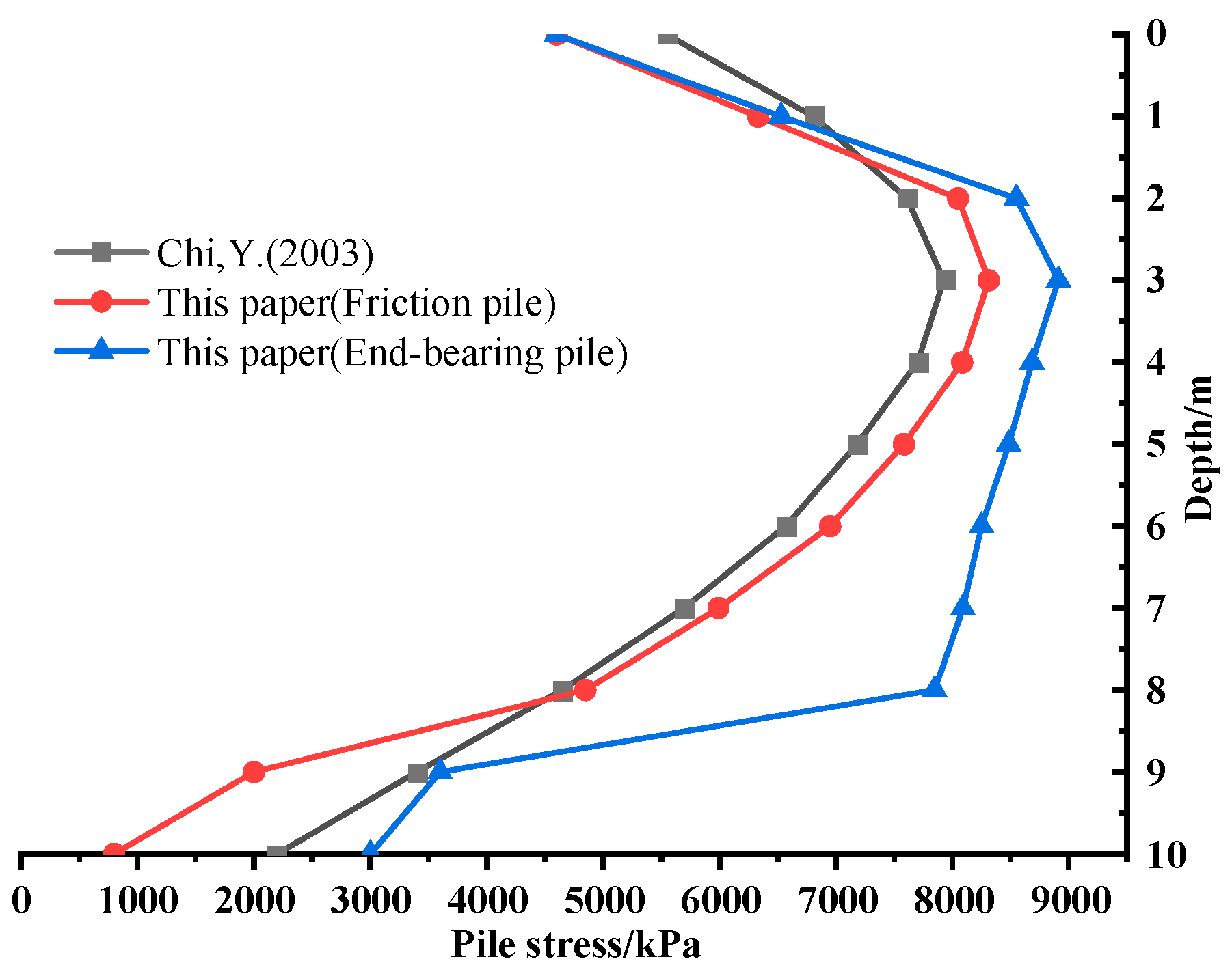
In order to validate the effectiveness of the results obtained in this study, a comparison was made with the computational method presented in [7]. The comparison results are shown in Figure 17. In [7], a finite element analysis was employed to investigate the influence of the cushion layer, pile length, soil modulus, and pile spacing on foundation settlement and stress distribution. Therefore, the same research object and computational parameters as those in [7] were selected for comparison. However, unlike [7], this study considered the negative skin friction on the pile and the end-bearing effect. The comparison of the calculated results for the pile stress along the depth is shown in Figure 17, which indicates a close agreement between the variations in pile stress. The discrepancies observed can mainly be attributed to two factors:
- (1)
- Element type: Ref. [7] employed 20-node solid elements, while this study used 8-node solid elements. The difference in the displacement interpolation functions between the two types of elements arose from the incomplete quadratic polynomial interpolation functions of the 20-node elements, leading to certain computational errors.
- (2)
- Frictional resistance and end-bearing effect: In this study, the calculation considered the negative skin friction on the pile and the end-bearing effect. Contact elements were used to simulate the interaction between the pile and the soil, and the influence of the end-bearing effect when the pile bottom directly contacted the bedrock was also calculated.
In conclusion, this study contributes to the understanding of composite foundation behavior and provides insights for optimizing pile design parameters. Further research is warranted to address the limitations and ensure the safety and reliability of structures in practical applications.
6. Conclusions
Based on a finite element numerical simulation, this study constructed a three-dimensional numerical model of a composite foundation consisting of concrete piles, inter-pile soil, cushion layers, and the underlying rock–soil structure, and analyzed its stress–strain variations and the mechanical load-bearing mechanism of the pile–soil interaction. The main conclusions are as follows:
- (1)
- The vertical stress of both the pile and the soil can be divided into three stages in the depth direction, from the pile’s top to the pile’s bottom. The stress diffusion of the pile undergoes a sharp increase, followed by a gradual decrease, and then a sharp decrease, while the stress diffusion of the soil is opposite to that of the pile.
- (2)
- The displacement of the pile can be divided by a critical depth. Above the critical depth, the displacement of the pile gradually decreases with depth, while below the critical depth, the displacement of the pile slightly increases with depth.
- (3)
- Under other identical conditions, end-bearing piles, due to their end-bearing effects and higher stiffness, exhibit larger vertical normal stresses and smaller deformations compared to friction piles, resulting in a higher bearing capacity for composite foundations.
- (4)
- The influence of the soil elastic modulus on the bearing characteristics of both the pile and the soil is very weak. In contrast, the bearing characteristics are mainly affected by the elastic modulus of the pile.
- (5)
- With an increase in soil depth, the stress diffusion effect of the soil becomes more pronounced. The additional vertical forces on all piles and inter-pile soil, as well as the ratio of additional vertical forces to the top load, gradually decrease. These trends are positively correlated with the elastic modulus of the pile and negatively correlated with the elastic modulus of the soil.
Author Contributions
Conceptualization, S.S., X.Z., W.L., Z.L., K.L., H.X. and P.H.; methodology, Z.L., W.L. and H.X.; software, X.Z., Z.L. and K.L.; validation, S.S., W.L., H.X., K.L. and P.H.; formal analysis, Z.L. and K.L.; investigation, Z.L., W.L., H.X. and P.H.; resources, S.S., W.L., H.X. and P.H.; data curation, W.L., H.X. and P.H.; writing—original draft preparation, K.L.; writing—review and editing, Z.L. and S.S.; visualization, W.L., H.X. and P.H.; supervision, X.Z., W.L. and Z.L.; project administration, W.L., H.X., P.H. and Z.L.; funding acquisition, Z.L. All authors have read and agreed to the published version of the manuscript.
Funding
This research was funded by the National Natural Science Foundation of China, grant numbers 12262016 and 12162018, and the Yunnan Province Xingdian Talent Support Plan (XDYC-CYCX-2022-0041).
Institutional Review Board Statement
Not applicable.
Informed Consent Statement
Not applicable.
Data Availability Statement
The original contributions presented in the study are included in the article, and further inquiries can be directed to the corresponding author.
Conflicts of Interest
Authors Wenlian Liu, Hanhua Xu and Pengwei Han were employed by the company China Nonferrous Metals Industry Co., Ltd. All authors declare that the research was conducted in the absence of any commercial or financial relationships that could be construed as a potential conflict of interest.
References
- Gong, X.; Chen, Z. Discussion on Some Key Issues Related to Foundation Engineering. Build. Struct. 2021, 51, 1–4. [Google Scholar] [CrossRef]
- Gong, X. Generalized Composite Foundation Theory and Engineering Application. Chin. J. Geotech. Eng. 2007, 29, 1–13. [Google Scholar]
- Guo, Z.X.; Huo, D. Computation of stress ratio of piles to soil and bearing behavior of rigid pile composite foundation. Rock Soil Mech. 2006, 27, 797–802. [Google Scholar] [CrossRef]
- Xu, Y. Establishment of Three Dimensional Composite Model and Its Application to Composite Foundation with Granular Piles. Chin. J. Rock Mech. Eng. 2004, 23, 3405–3412. [Google Scholar]
- Qiao, J.; Li, X. Numerical Analysis of Settlement of Composite Foundation and Natural Foundation under Earthquake Action. Earthq. Eng. Eng. Vib. 2006, 26, 245–247. [Google Scholar] [CrossRef]
- XU, Y.; Chen, G. Site Seismic Response Analysis of Composite Foundation Mixed with Cement Piles. J. Disaster Prev. Mitig. Eng. 2005, 25, 182–188. [Google Scholar]
- Chi, Y.; Song, E. Analysis of Bearing Performance of Rigid Pile Composite Foundation under Vertical Loads. Eng. Mech. 2003, 20, 9–14. [Google Scholar]
- Zhang, Y.; Pan, Z. Research on Mechanism and Dynamic Characteristics of Composite Foundation with Multi-Type Piles. China Earthq. Eng. J. 2015, 37, 82–87. [Google Scholar]
- Zhang, X.; Yu, D.; Zhu, K.; Zhao, A.; Ren, M. The Horizontal Bearing Characteristics and Microscopic Soil Deformation Mechanism of Pile-Bucket Composite Foundation in Sand. Appl. Sci. 2024, 14, 907. [Google Scholar] [CrossRef]
- Zhang, L.; Wang, T.; Zhao, Z.; Jin, X. Research on Bearing Difference between Single-Pile Composite Foundation Field Test and Group-Pile Composite Foundation of High-Rise Buildings. Buildings 2023, 13, 2127. [Google Scholar] [CrossRef]
- Zhao, M.; Long, J. Comparative Analysis of Model Tests on Different Types of Composite Foundations. Chin. J. Geotech. Eng. 2013, 35, 611–618. [Google Scholar]
- Guo, Y.; Lv, C.; Hou, S.; Liu, Y. Experimental Study on the Pile-Soil Synergistic Mechanism of Composite Foundation with Rigid Long and Short Piles. Math. Probl. Eng. 2021, 2021, 6657116. [Google Scholar] [CrossRef]
- Dai, G.; Feng, S. Experimental Study on Bearing Performance of Caisson-Cushionpiles Composite Foundation Under Low Cyclic Loading. China J. Highw. Transp. 2022, 35, 142–153. [Google Scholar] [CrossRef]
- Li, L.; Ye, J. Experimental Study on Bearing Characteristics of Nodular Pile Composite Foundation in Soft Soil Area. Chin. J. Undergr. Space Eng. 2020, 16, 986–992. [Google Scholar]
- Wang, C.; Zeng, F.; Gao, S.; Yuan, G. Experimental Study on Reinforcement of Marine Clay by Artificial Hard Shell Layer Composite Foundation. Mar. Georesour. Geotechnol. 2023, 41, 1393–1403. [Google Scholar] [CrossRef]
- Yu, J.; Zhou, J.; Gong, X.; Xu, R.; Li, J.; Xu, S. Centrifuge Study on Behavior of Rigid Pile Composite Foundation under Embankment in Soft Soil. Acta Geotech. 2021, 16, 1909–1921. [Google Scholar] [CrossRef]
- Wu, M.; Liu, B.; Xie, Y.; Ning, D. The Feasibility Study on Treating Soft-Soil with Lightweight-Pile Composite Foundation. Integr. Ferroelectr. 2019, 199, 30–45. [Google Scholar] [CrossRef]
- Zhu, K.; Wei, G.; Xu, R. Research on in-situ tests of pile load transfer behaviors in composite foundation with rigid- flexible piles. Rock Soil Mech. 2009, 30, 201–205+210. [Google Scholar] [CrossRef]
- Ding, X.; Zhang, T.; Li, P.; Cheng, K. A Theoretical Analysis of the Bearing Performance of Vertically Loaded Large-Diameter Pipe Pile Groups. J. Ocean Univ. China 2016, 15, 57–68. [Google Scholar] [CrossRef]
- Sulaiman Al-Ne’aimi, R.M.; Hussain, M.S. Numerical Modeling and Parametric Study of Piled Rafts Foundations. Arab. J. Geosci. 2021, 14, 447. [Google Scholar] [CrossRef]
- Li, L.; Zhang, P.; Long, Q. Design scheme of variable stiffness leveling of pile group in typical soft soil stratum. J. Railw. Sci. Eng. 2022, 19, 1288–1297. [Google Scholar] [CrossRef]
- Zhang, G.; Zhang, J. Relationship between pile-soil composite foundation bearing capacity and replacement rate of sluice. Eng. J. Wuhan Univ. 2013, 46, 328–333. [Google Scholar]
Figure 1.
Schematic diagram of all piles and inter-pile soils in the composite foundation: (a) all piles and inter-pile soils; (b) all piles; and (c) all inter-pile soils.
Figure 1.
Schematic diagram of all piles and inter-pile soils in the composite foundation: (a) all piles and inter-pile soils; (b) all piles; and (c) all inter-pile soils.
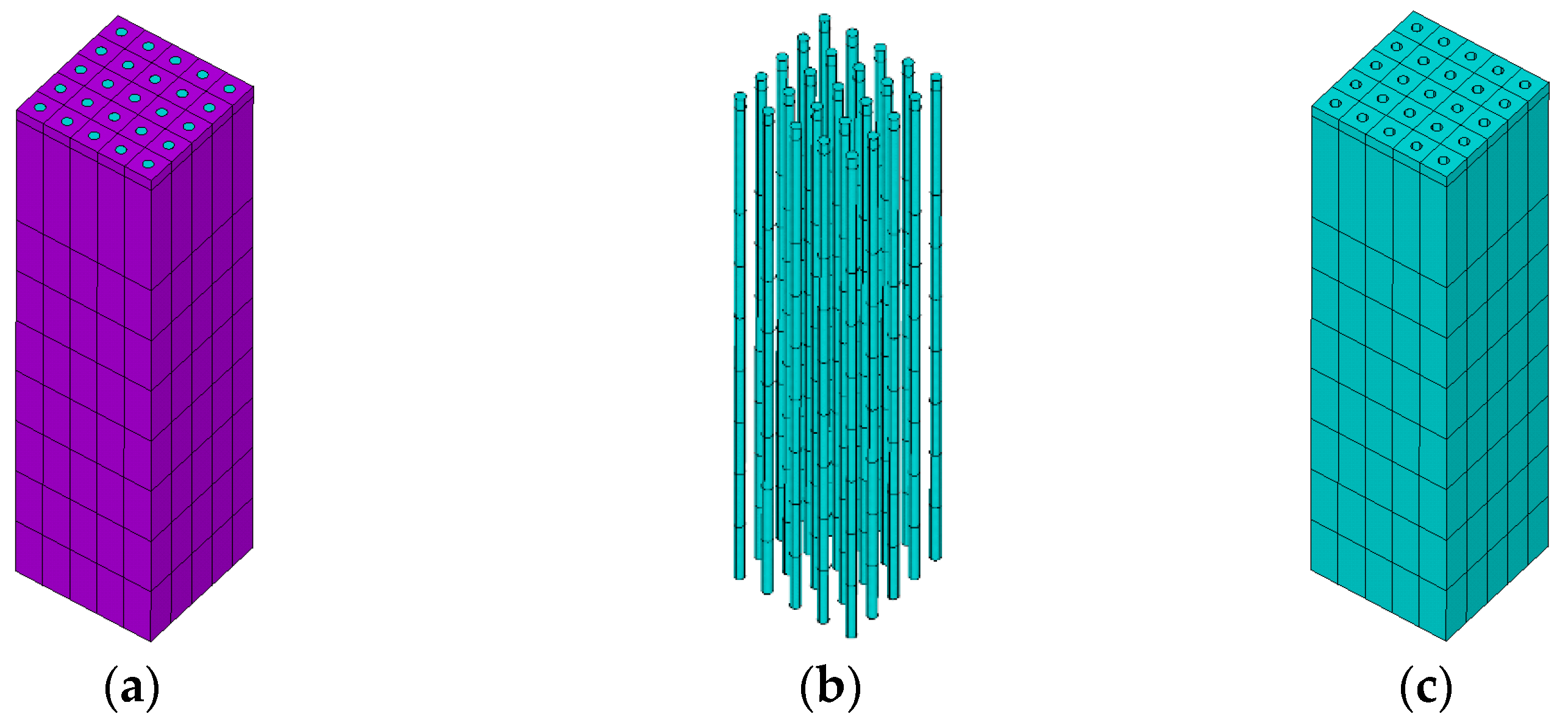
Figure 2.
Schematic diagram of central pile and inter-pile soil: (a) central pile and inter-pile soil; (b) central pile; and (c) inter-pile soil.
Figure 2.
Schematic diagram of central pile and inter-pile soil: (a) central pile and inter-pile soil; (b) central pile; and (c) inter-pile soil.

Figure 3.
Project rendering.
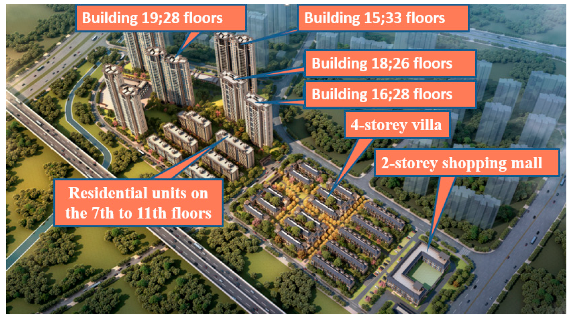
Figure 4.
Schematic of the composite foundation calculation model dimensions: (a) end-bearing pile composite foundation; (b) friction pile composite foundation; and (c) composite foundation plan view.
Figure 4.
Schematic of the composite foundation calculation model dimensions: (a) end-bearing pile composite foundation; (b) friction pile composite foundation; and (c) composite foundation plan view.
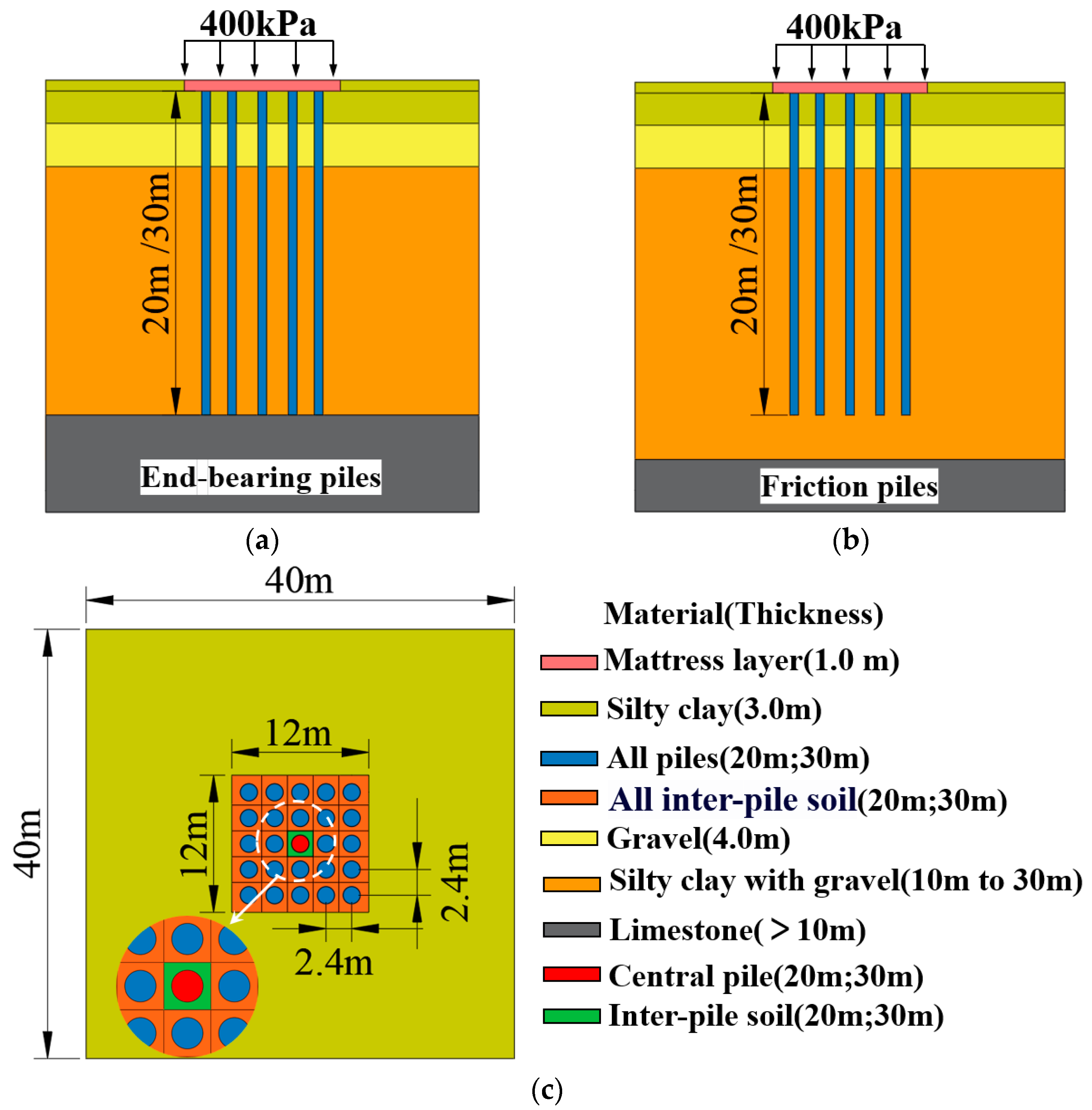
Figure 5.
Finite element models of various components of the composite foundation.
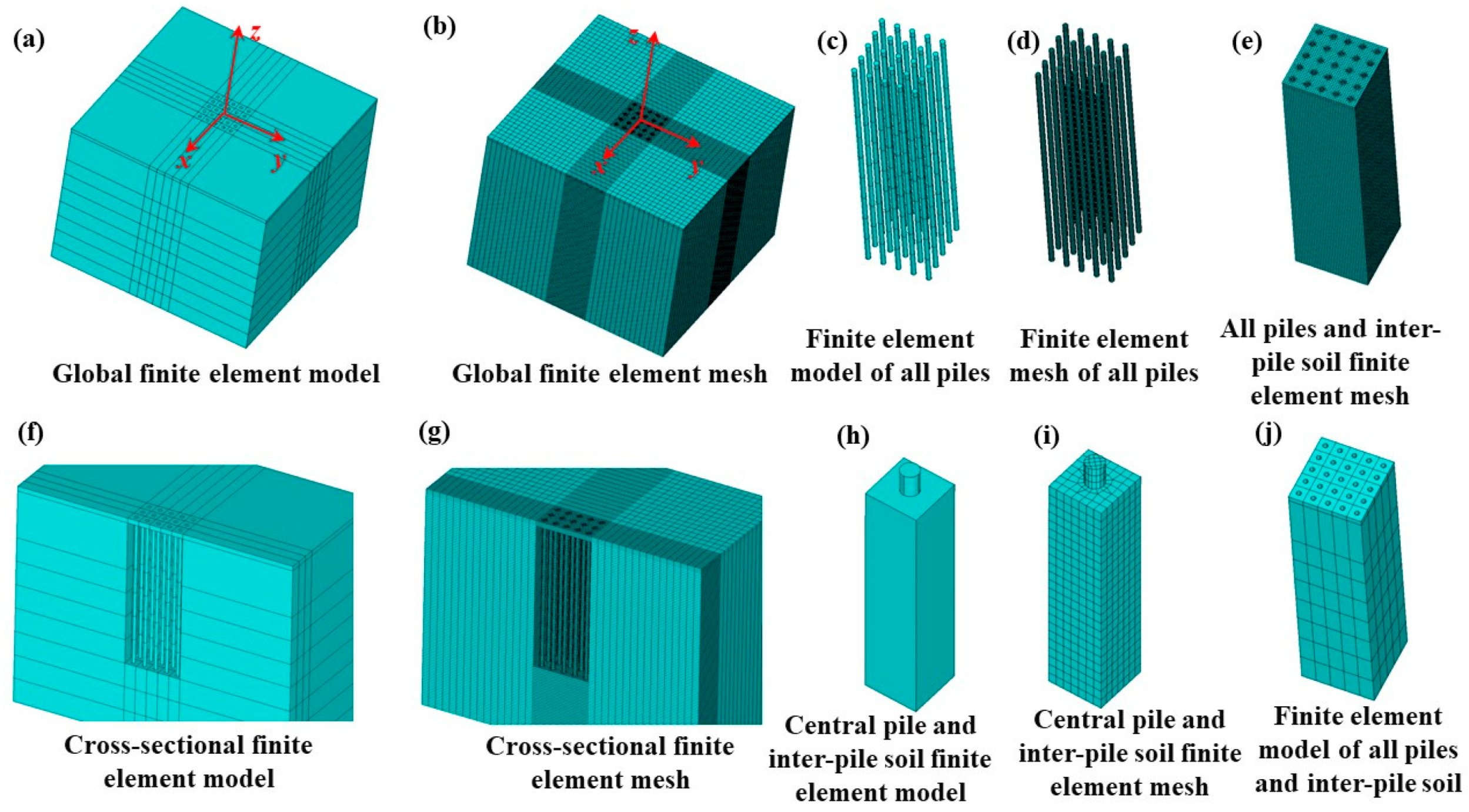
Figure 6.
Isoline of initial geostress field/Pa: (a) vertical stress; (b) horizontal stress.

Figure 7.
Stress distribution in piles and soil under upper load: (a) pile stress; (b) soil stress.
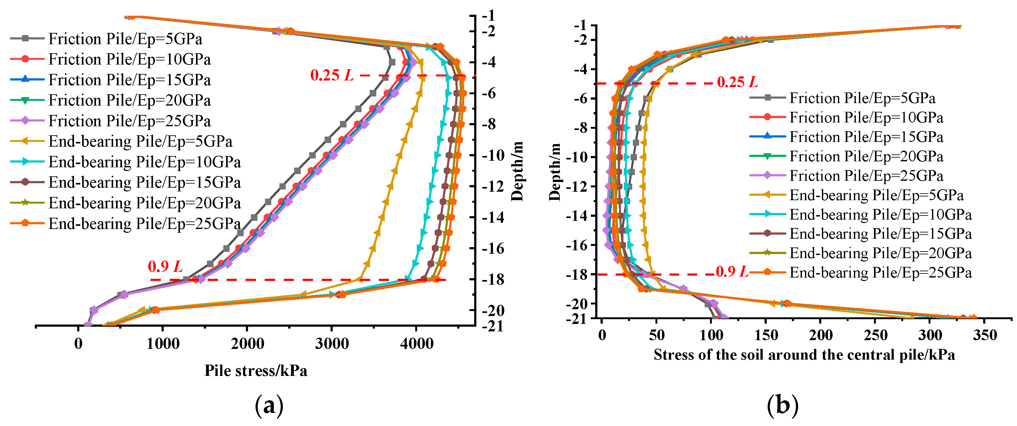
Figure 8.
Influence of soil elastic modulus on stress distribution of two types of piles: (a) stress distribution of friction piles; (b) stress distribution of end-bearing piles.
Figure 8.
Influence of soil elastic modulus on stress distribution of two types of piles: (a) stress distribution of friction piles; (b) stress distribution of end-bearing piles.

Figure 9.
Distribution of displacement in piles and soil under upper load: (a) pile displacement; (b) soil displacement.
Figure 9.
Distribution of displacement in piles and soil under upper load: (a) pile displacement; (b) soil displacement.

Figure 10.
Influence of soil elastic modulus on displacement distribution of two pile types: (a) displacement of friction pile; (b) displacement of end-bearing pile.
Figure 10.
Influence of soil elastic modulus on displacement distribution of two pile types: (a) displacement of friction pile; (b) displacement of end-bearing pile.
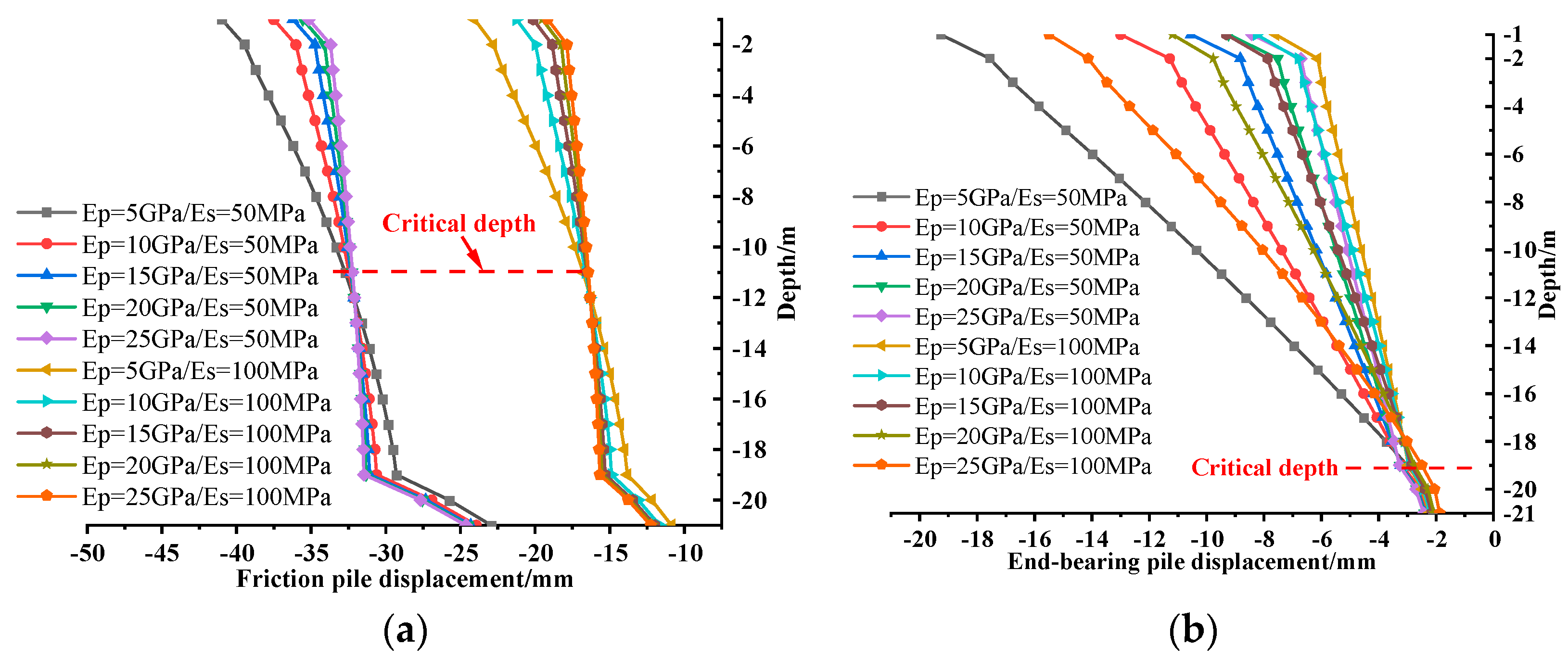
Figure 11.
Variation in the additional axial force on the central pile along the depth direction with a pile length of 30 m: (a) the additional axial force of the central pile; (b) the ratio of the additional axial force on the central pile.
Figure 11.
Variation in the additional axial force on the central pile along the depth direction with a pile length of 30 m: (a) the additional axial force of the central pile; (b) the ratio of the additional axial force on the central pile.
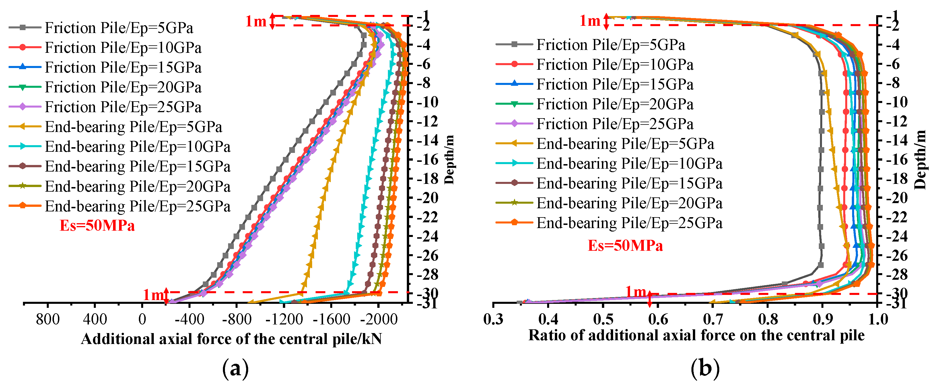
Figure 12.
Variation in the additional axial forces along the depth direction for the central pile and inter-pile soil with a soil elastic modulus of 50 MPa: (a) the additional axial force of the central pile; (b) the additional vertical force of the soil around the central pile.
Figure 12.
Variation in the additional axial forces along the depth direction for the central pile and inter-pile soil with a soil elastic modulus of 50 MPa: (a) the additional axial force of the central pile; (b) the additional vertical force of the soil around the central pile.

Figure 13.
Variation in the additional axial forces along the depth direction for the central pile and inter-pile soil with a soil elastic modulus of 100 MPa: (a) the additional axial force of the central pile; (b) the additional vertical force of the soil around the central pile.
Figure 13.
Variation in the additional axial forces along the depth direction for the central pile and inter-pile soil with a soil elastic modulus of 100 MPa: (a) the additional axial force of the central pile; (b) the additional vertical force of the soil around the central pile.
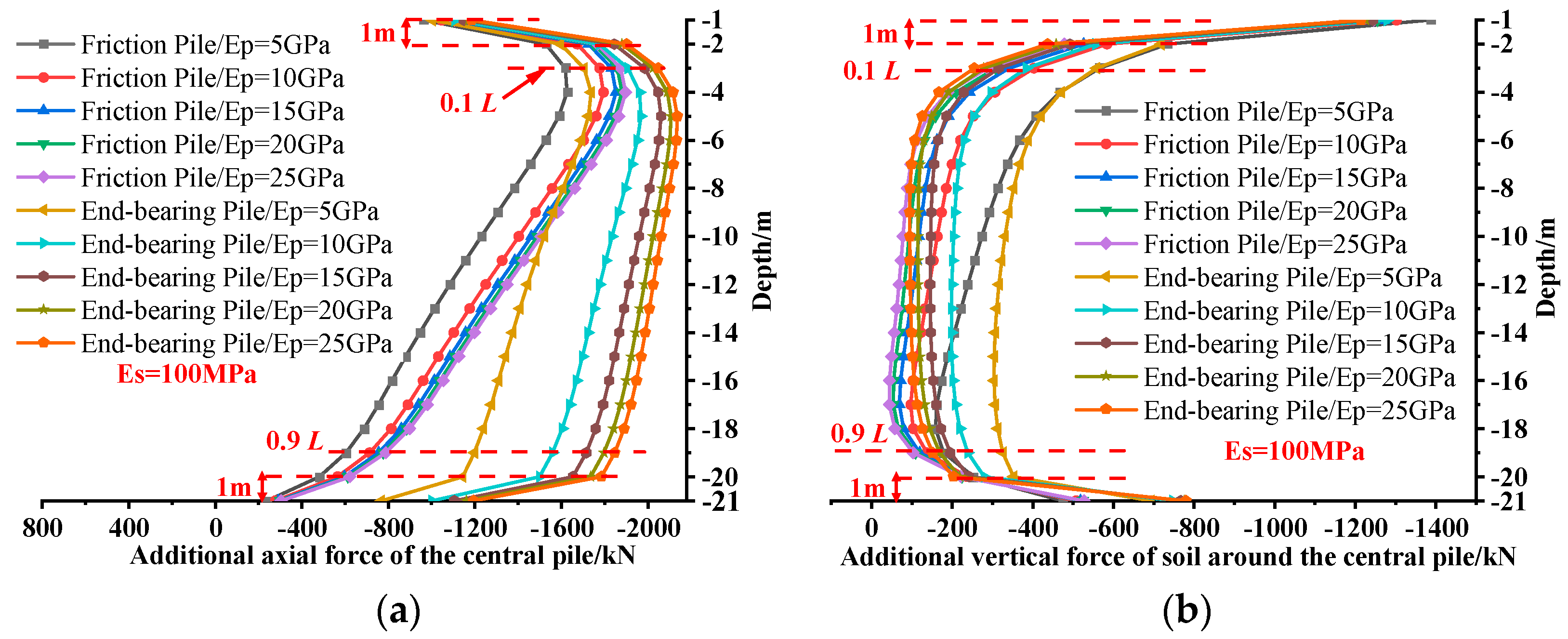
Figure 14.
Proportion of vertical forces between central pile and inter-pile soil: (a) soil elastic modulus of 50 MPa; (b) soil elastic modulus of 100 MPa.
Figure 14.
Proportion of vertical forces between central pile and inter-pile soil: (a) soil elastic modulus of 50 MPa; (b) soil elastic modulus of 100 MPa.

Figure 15.
Variation in additional vertical forces along depth direction for all piles and inter-pile soil with a pile length of 30 m: (a) sum of additional vertical force on piles and inter-pile soil; (b) ratio of additional vertical forces on piles and inter-pile soil to upper load.
Figure 15.
Variation in additional vertical forces along depth direction for all piles and inter-pile soil with a pile length of 30 m: (a) sum of additional vertical force on piles and inter-pile soil; (b) ratio of additional vertical forces on piles and inter-pile soil to upper load.
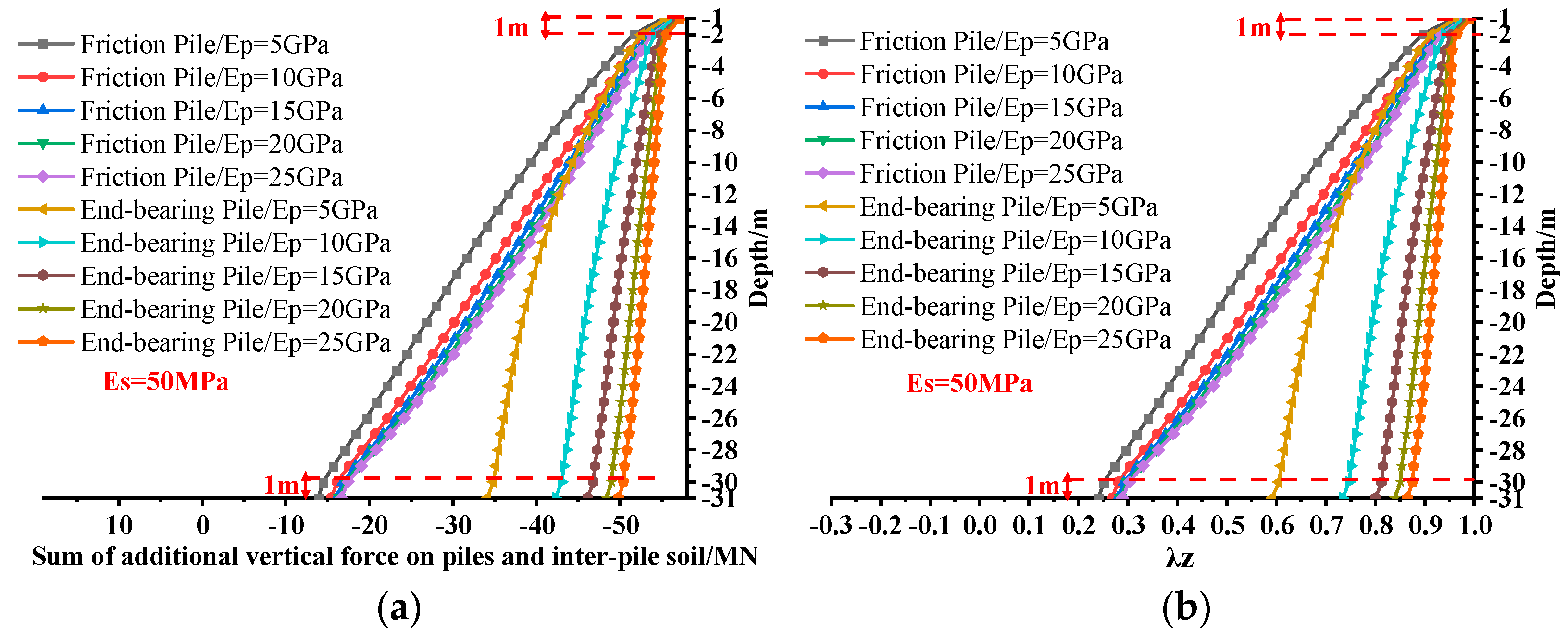
Figure 16.
Variation in additional vertical forces along depth direction for all piles and inter-pile soil with a pile length of 20 m: (a) sum of additional vertical force on piles and inter-pile soil; (b) ratio of additional vertical forces on piles and inter-pile soil to upper load.
Figure 16.
Variation in additional vertical forces along depth direction for all piles and inter-pile soil with a pile length of 20 m: (a) sum of additional vertical force on piles and inter-pile soil; (b) ratio of additional vertical forces on piles and inter-pile soil to upper load.

Figure 17.
Comparison of calculation results [7].
Figure 17.
Comparison of calculation results [7].

Table 1.
Physical and mechanical parameters of subsoil for the foundation.
| Serial Number | Material Type | Thickness of Soil Layer/m | Density/kg/m3 | Elastic Modulus/MPa | Poisson’s Ratio |
|---|---|---|---|---|---|
| 1 | Mattress layer | 1.0 | 2100 | 100 | 0.30 |
| 2 | Silty clay | 3.0 | 1900 | 20 | 0.32 |
| 3 | Gravel | 4.0 | 2200 | 80 | 0.28 |
| 4 | Angular gravelly silty clay | 10.0~30 | 1800 | 50 | 0.32 |
| 5 | Limestone | 12.0 | 2400 | 2000 | 0.28 |
| 6 | Pile | 20.0; 30.0 | 2400 | 5000~25,000 | 0.27 |
Table 2.
Computational conditions for three-dimensional numerical simulation of composite foundation.
Table 2.
Computational conditions for three-dimensional numerical simulation of composite foundation.
| Pile Length L/m | Soil Elastic Modulus Es/MPa | Concrete Pile Elastic Modulus Ep/MPa | Pile Type |
|---|---|---|---|
| 20; 30 | 50; 100 | 5000; 10,000; 15,000; 20,000; 25,000 | Friction pile; end-bearing friction pile |
Table 3.
Comparison of ratios of all piles and inter-pile soil to top load under different conditions.
Table 3.
Comparison of ratios of all piles and inter-pile soil to top load under different conditions.
| Parameters | Comparison of Conditions | Ratio of Additional Vertical Force to Top Load λt/λb | Increase in the Ratio λ, Denoted as Δλt/Δλb | |
|---|---|---|---|---|
| Pile length L | 20 m | Friction piles Ep = 5 GPa Es = 50 MPa | 0.953/0.298 | 0.363%/−19.364% |
| 30 m | 0.956/0.241 | |||
| Soil elastic modulus Es | 50 MPa | Friction piles Ep = 5 GPa L = 20 m | 0.953/0.298 | −1.610%/−8.708% |
| 100 MPa | 0.938/0.272 | |||
| Pile elastic modulus Ep | 5 GPa | End-bearing friction piles Es = 50 MPa L = 20 m | 0.965/0.696 | 1.565%/ 13.023% |
| 10 GPa | 0.980/0.800 | |||
| Pile type | Friction piles | L = 20 m Ep = 5 GPa Es = 50 MPa | 0.953/0.298 | 1.222%/133.277% |
| End-bearing friction piles | 0.965/0.696 | |||
Disclaimer/Publisher’s Note: The statements, opinions and data contained in all publications are solely those of the individual author(s) and contributor(s) and not of MDPI and/or the editor(s). MDPI and/or the editor(s) disclaim responsibility for any injury to people or property resulting from any ideas, methods, instructions or products referred to in the content. |
© 2024 by the authors. Licensee MDPI, Basel, Switzerland. This article is an open access article distributed under the terms and conditions of the Creative Commons Attribution (CC BY) license (https://creativecommons.org/licenses/by/4.0/).
Share and Cite
MDPI and ACS Style
Sui, S.; Zhang, X.; Lu, K.; Li, Z.; Liu, W.; Xu, H.; Han, P. Finite Element Analysis of Combined Bearing Characteristics of Pile–Soil Interaction in Composite Foundation. Appl. Sci. 2024, 14, 3894. https://doi.org/10.3390/app14093894
AMA Style
Sui S, Zhang X, Lu K, Li Z, Liu W, Xu H, Han P. Finite Element Analysis of Combined Bearing Characteristics of Pile–Soil Interaction in Composite Foundation. Applied Sciences. 2024; 14(9):3894. https://doi.org/10.3390/app14093894
Chicago/Turabian StyleSui, Sugang, Xiaoyan Zhang, Kaiyu Lu, Ze Li, Wenlian Liu, Hanhua Xu, and Pengwei Han. 2024. "Finite Element Analysis of Combined Bearing Characteristics of Pile–Soil Interaction in Composite Foundation" Applied Sciences 14, no. 9: 3894. https://doi.org/10.3390/app14093894
Note that from the first issue of 2016, this journal uses article numbers instead of page numbers. See further details here.