Brief Report

Maximum Operational Fluence Limits for Temporally Shaped Nanosecond Long Pulses

1
Central Laser Facility, STFC Rutherford Appleton Laboratory, Chilton, Didcot OX11 0QX, UK
2
INFN-LNF, Via Enrico Fermi 40, 00044 Frascati, Italy
*
Author to whom correspondence should be addressed.
Appl. Sci. 2024, 14(10), 4211; https://doi.org/10.3390/app14104211
Submission received: 21 February 2024 / Revised: 18 April 2024 / Accepted: 27 April 2024 / Published: 16 May 2024
(This article belongs to the Section Optics and Lasers)

Abstract

:

Featured Application

Large scale laser operation. Complex laser use.

Abstract

The maximum energy at which a laser can be operated safely is a matter of paramount importance. This is patently related to laser induced damage. In the nanosecond regime, this poses a unique challenge, as it is not solely influenced by laser intensity or thermal load. Instead, it arises from the cumulative effects that includes those two factors. While extensive research has explored this dependence for various pulse lengths, the exploration of different longitudinal modes and temporal shapes is relatively limited. Our study aims to fill this gap by determining the safe operational fluence for any pulse shape, leveraging established dependencies on pulse duration. We propose a straightforward and adaptable method to ascertain these operational limits, independent of the type or origin of laser damage. This approach allows us to derive fluence limits for diverse pulse shapes.

1. Introduction

The control of the temporal shape of nanosecond pulses has found applications across various fields, ranging from industrial applications such as laser peening [1,2,3] to ultracold molecular formation [4,5,6]. In high energy laser facilities, temporal shaping has been used in the development of lasers themselves via optical parametric chirped-pulse amplification (OPCPA) techniques [7,8,9], and are used to create high density conditions [10] mostly for studies in warm dense matter [11,12] and plasma physics [13], namely in inertial confinement fusion (ICF) [14].
The maximum fluence at which a laser can operate is closely linked to the laser damage threshold, attributed to various causes [15,16,17,18,19,20,21,22,23,24], including local thermal effects, thermally induced stress [18,21,22], electron avalanche [15], and facture mechanics [16] driving damage. In shorter time scales (ps to hundreds of ps), optical damage arises from multiphoton processes like multiphoton absorption [23], ionization, and electron avalanche [15,24]. With even shorter pulses (in the fs regime), self-focusing and filamentation become crucial effects [24], potentially deforming the pulse’s spatial and temporal profile and introducing hot spots, making damage more unpredictable.
In the nanosecond time scale, damage is a probabilistic and cumulative process involving precursors [17,21,22,25,26] and imperfections in optics, such as nanoparticles, accumulating damage. Thermal heating acts as a determinant to the maximum energy achievable [20]. The accumulation is not linear and depends on diffusion [26], thermal factors [20], or other considerations. The process is wavelength-dependent [27] and even dependent on the morphology of defects [21].
In larger laser systems, the complexity increases as different types of damage must be considered, such as bulk and surface damage [28,29,30]. Various optics will have different maximum operational fluence, with gratings being particularly sensitive to damage [31,32,33]. Moreover, damage can propagate between optics due to hot spots created by small damage sites earlier in the system or ghost reflections [31,32].
Irrespective of the origin of laser damage, it is fundamentally important to have prior knowledge of the maximum fluence at which the laser system can be operated safely, regardless of the pulse temporal profile. Testing all possible pulse shapes is impractical, necessitating the use of an indirect method. While a single point failure, where one optic is substantially weaker than the rest, simplifies this process, it is not always the case.
In the Vulcan laser facility [34], the development of pulse shaping [35] prompted the evaluation of the energy deliverable in a nanosecond-shaped pulse. This becomes even more critical with the advent of high-repetition-rate ns lasers [36,37]. Previous studies, considering damage energy proportional to a fractional power of pulse duration, do not align with the fluence limits observed in the Vulcan laser facility [20,23,26]. Due to the laser’s nature, testing all facility elements is not feasible, necessitating the deduction of energy limits using the cumulative principle and the established maximum operational fluence.
It is crucial to clarify that the objective is not to evaluate damage but rather to determine the maximum energy at which a laser can be operated. The focus is not on identifying the origin of damage or any other limitations to laser energy limits.

2. Pulse Shape Versus Pulse Length

Safe operational fluences for 1–6 ns top hat pulses have been determined from past damage incidents, represented by the orange dots in Figure 1. To describe this data, we have introduced two numerical fits, as illustrated by the curves given by (1). Throughout our analysis, we will denote the maximum fluence of a square pulse as J m a x .
J m a x f i t 1 = c 1 1 exp τ c 2 J m a x f i t 2 = c 3 τ 1 + τ c 4 2
The parameter τ represents the pulse duration in our analysis. The first fit corresponds to a dependency akin to that reported by Koldunov et al. [20], notably diverging from the τ 1 2 relationship found in other literature [23,26]. We employ two fit functions to showcase the sensitivity of our results to fluctuations. The parameters in the fit functions are as follows: c 1 = 3.68 J/cm2; c 2 = 0.5 ns; c 3 = 6.2 J/(cm2· ns); c 4 = 0.6 ns.

3. Maximum Operational Fluence for Different Pulse Shapes

In this study, we operate under the assumption that damage is cumulative. This aligns with methodologies applied elsewhere [26], where a phenomenological model is considered, involving the creation and diffusion of damage particles called damageonium by Carr et al. in [38]. This is mainly heat but can also be mechanical deformation or particles and as such propagates through the system. The cumulative effect eventually reaches a threshold where damage is produced. We justify this assumption based on the pulse duration’s order of magnitude in this system, which has a minimum pulse duration of 200 ps and the smallest features on the order of 100 ps (limited by fast electronics). Please note that this is far from avalanche and multiphoton ionization phenomena [23], which mainly depend on peak intensity. Additionally, a significant reason to consider cumulative damage in large-scale lasers is that imperfections or damage in certain parts of the laser system can propagate forward or backward. This occurs either through simple diffraction or the creation of back reflections and ghosts [39]. With this condition, the accumulation of damage particles can be given by the following quantity D damaging the system [26,38].
D = g ( t τ ) I ( t ) d t
Here, g ( t ) represents the impulse response function of the diffusion process of the damage particles [38]. Damage particles generated at each point of the pulse are proportional to the intensity and diffuse according to the function g ( t ) over time, relative to the pulse’s initiation. The temporal intensity profile of the pulse is denoted by I ( t ) (Equation (2)). Damage initiation occurs once the cumulative damage, denoted as D, reaches a certain probability threshold, D i . This threshold is reached when the fluence of the pulse attains the damage threshold fluence, Φ D . The temporal intensity profile of such a pulse is expressed in Equation (3).
I D ( t ) = Φ D p ( t ) d t p ( t )
where p ( t ) is the temporal shape of the pulse. This implies that the accumulated damaged particles at the point of damage initiation can be expressed as
D i = Φ D p ( t ) d t max τ g ( t τ ) p ( t ) d t
At this juncture, we can utilize the fluence employed to define f ( t ) = g ( t ) / D i . Remarkably, the probability of damage initiation remains consistent for any pulse shape, irrespective of its form. By substituting this into Equation (4), the damage threshold can be expressed as
Φ D = p ( t ) d t max τ f ( t τ ) p ( t ) d t
The relationship between the maximum fluence and the probability of damage is delineated in Equations (1) and (2), assuming a square pulse—easily attainable through a shapeable laser [35]. Leveraging this understanding, we can compute the time-dependent f ( t ) and subsequently reintroduce it into Equation (5). This process is carried out to extend the generalization to any pulse shape and duration.
Boundary conditions are applied at zero time. As a result, the maximum fluence is expressed as
f ( t ) = d t J m a x ( t ) d t + α δ ( t )
where the constant value α is
α = lim t 0 t J m a x ( t )
One can then conclude that the damage threshold for any pulse shape has
Φ D = p ( t ) d t max τ { p ( t + τ ) d t J m a x ( t ) d t d t + α }
For each one of the functions in Equation (1), we have
f 1 ( t ) = 1 c 1 1 1 exp t c 2 t / c 2 exp ( t / c 2 ) 1 exp ( t / c 2 ) 2 f 2 ( t ) = 1 c 3 c 4 2 t 1 + t c 4 2
The α constant is given by
α 1 = c 2 / c 1 α 2 = 1 / c 3
Regardless of the damage mechanism, Equations (6)–(8) remain valid.

4. Results

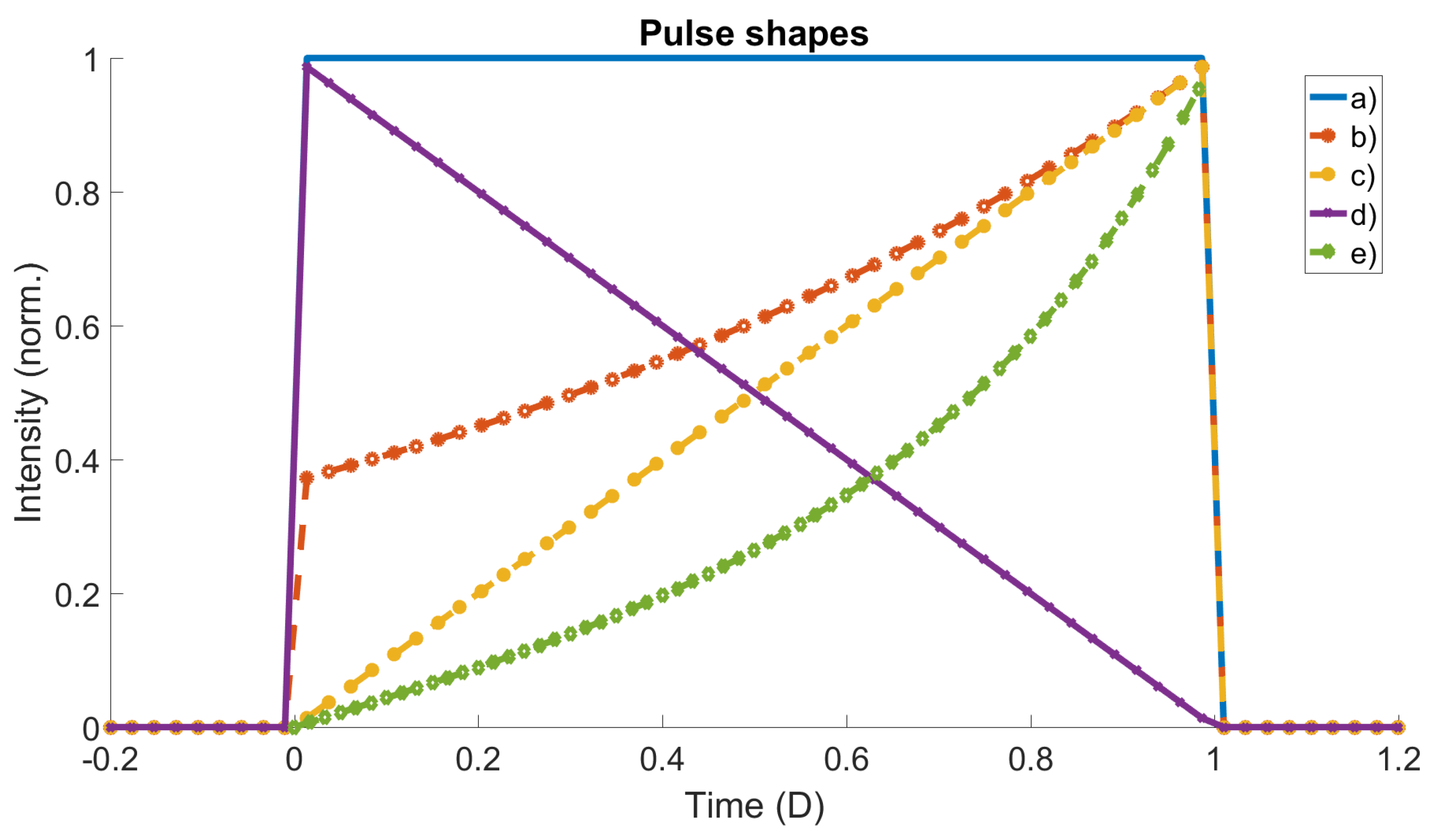
The provided equations were employed to analyze several pulse shapes, as depicted in Figure 2. In addition to top-hat, ramps, and exponential shapes, we also computed an example of a pulse shape before it reaches full saturation. This particular shape is reminiscent of the pulse profile required for isentropic compression [40] (indicated as curve ‘e’).
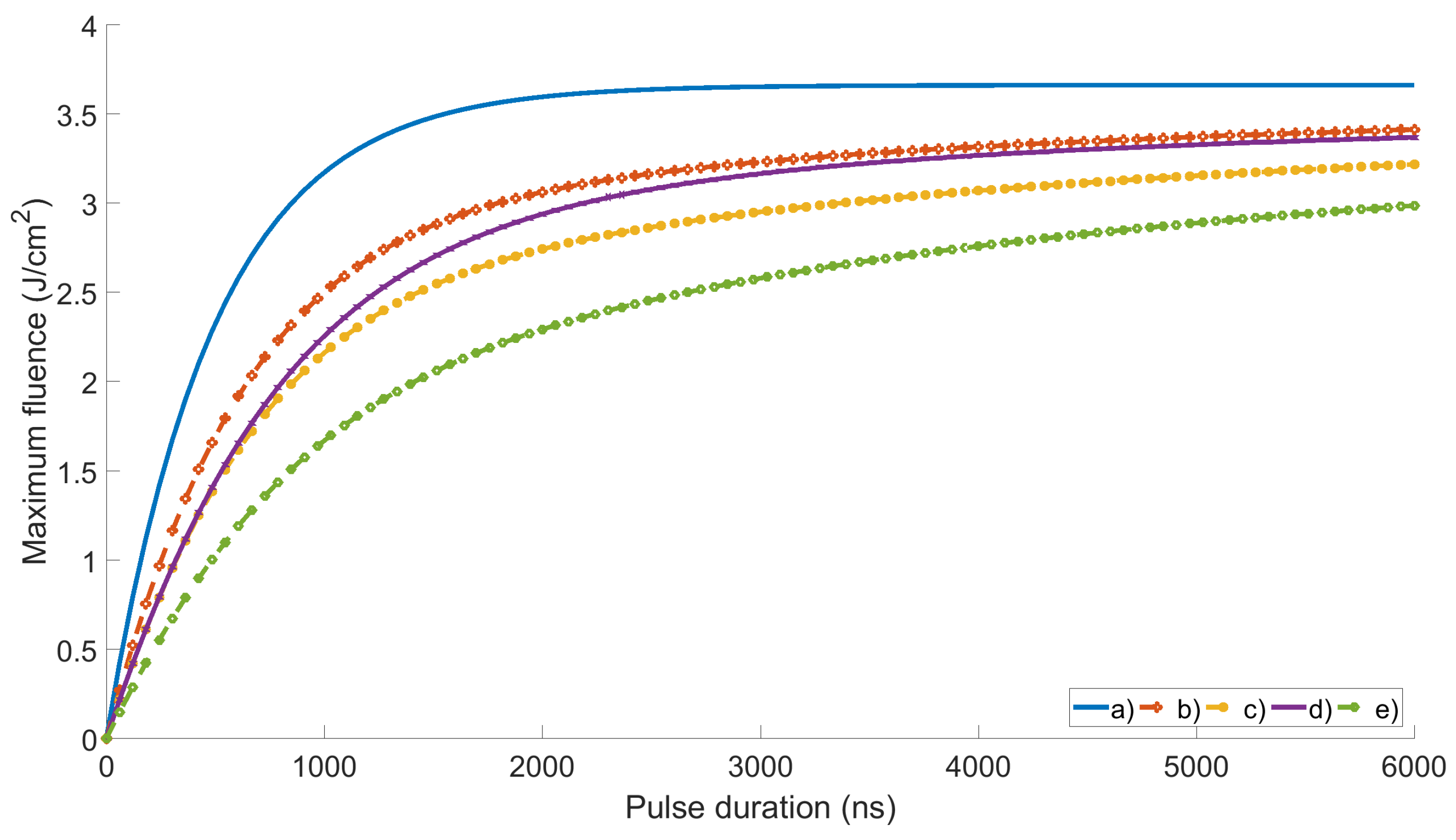
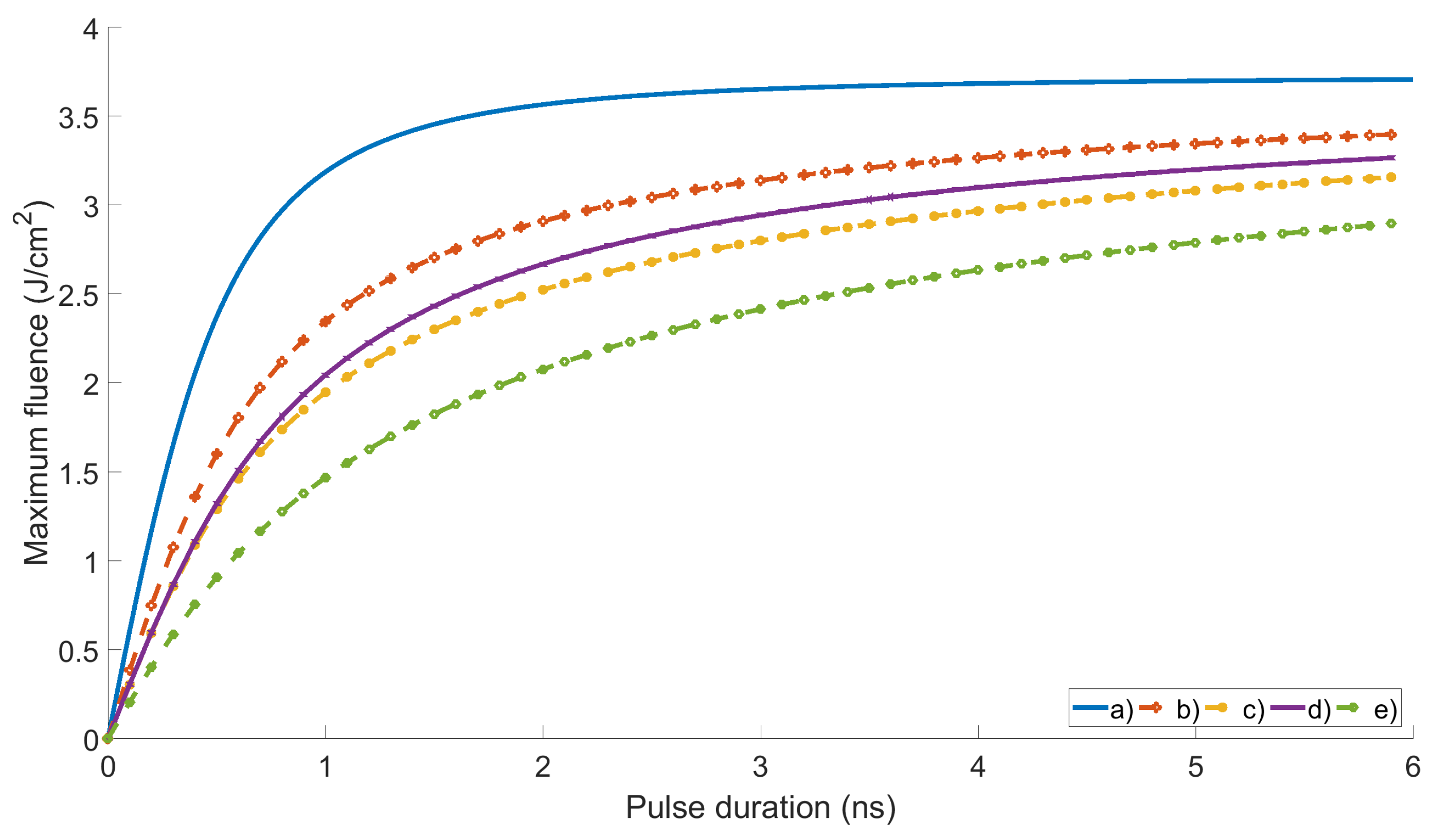
From these pulse shapes, we obtain a damage threshold as a function of pulse duration in Figure 3 for Fit Function 1 and Figure 4 for Fit Function 2.
In practical scenarios, the exact knowledge of the pulse shape may be uncertain. To assess the sensitivity of imperfections in the pulse shape to our method, we conducted simulations by introducing 10% white noise to the pulse shape and subsequently calculated the damage threshold. Remarkably, the damage threshold exhibited minimal variations, never exceeding 1%. This suggests that our method remains robust, allowing for the evaluation of the maximum operational energy even when the pulse shape is not precisely known.

5. Discussion

The maximum energy for any pulse duration is determined for a top hat profile, consistent with expectations, yielding the highest intensity for a given energy. The pulse length corresponding to the smallest fluence is observed in curve e.
Notably, the results for the inverse ramp differ from those for a forward ramp, emphasizing that an average pulse duration cannot be universally applied. A comparison of both fit curves reveals that only shape ‘e’ exhibits a noticeable difference. This indicates that, for most shapes (a–d), the maximum fluence we can operate is not dependent on the fit function used.

6. Conclusions

We have successfully demonstrated the capability of calculating the energy limit of a laser system for any pulse shape, regardless of the specific pulse shape or damage mechanism. Our calculations encompassed various pulse shapes commonly employed in large-scale facilities. This methodology allows us to leverage existing information, eliminating the need for impractical measurements of energy damage thresholds in our specific case. Even if variations in the maximum fluence are determined to be different from what is given in Equation (1) through Laser-Induced Damage Threshold (LIDT) results, this method remains applicable by employing Equations (6)–(8) to interpret LIDT outcomes.

Author Contributions

Conceptualization, P.O.; methodology, M.G. (Mario Galletti) and M.G. (Marco Galimberti) and P.O.; software, C.S.; validation, C.S. and P.O.; writing—original draft preparation, C.S. and P.O.; writing—review and editing, M.G. (Mario Galletti); supervision, P.O.; funding acquisition, M.G. (Marco Galimberti) All authors have read and agreed to the published version of the manuscript.

Funding

This work has been funded by UKRI.

Institutional Review Board Statement

Not applicable.

Informed Consent Statement

Not applicable.

Data Availability Statement

The data presented in this study are available on request from the corresponding author.

Conflicts of Interest

The authors declare no conflicts of interest.

References

  1. Patel, R.S.; Stock, M.L.; Sartania, Z.; Bovatsek, J.M.; Arai, A.Y.; Endert, H. Temporal pulse shaping using fiber laser technology: Nano-scaling for flexible industrial laser material processing. In Proceedings of the Third International Symposium on Laser Precision Microfabrication, Osaka, Japan, 27–31 May 2002; Volume 4830, pp. 352–356. [Google Scholar] [CrossRef]
  2. Özgören, K.; Öktem, B.; Ömer Ilday, F.; Pasin, E.; Eken, K. Micromachining with square-shaped 1 ns-long pulses from an all-fiber Yb-doped laser-amplifier system. In Advances in Optical Materials; Optical Society of America: Washington, DC, USA, 2011; p. AWA15. [Google Scholar] [CrossRef]
  3. Gill, A.S.; Zhou, Z.; Lienert, U.; Almer, J.; Lahrman, D.F.; Mannava, S.R.; Qian, D.; Vasudevan, V.K. High spatial resolution, high energy synchrotron x-ray diffraction characterization of residual strains and stresses in laser shock peened Inconel 718SPF alloy. J. Appl. Phys. 2012, 111, 084904. [Google Scholar] [CrossRef]
  4. Koch, C.P.; Shapiro, M. Coherent Control of Ultracold Photoassociation. Chem. Rev. 2012, 112, 4928–4948. [Google Scholar] [CrossRef] [PubMed]
  5. Pechkis, J.A.; Carini, J.L.; Rogers, C.E.; Gould, P.L.; Kallush, S.; Kosloff, R. Coherent control of ultracold 85Rb trap-loss collisions with nonlinearly frequency-chirped light. Phys. Rev. A 2011, 83, 063403. [Google Scholar] [CrossRef]
  6. Collins, T.A.; Malinovskaya, S.A. Manipulation of ultracold Rb atoms using a single linearly chirped laser pulse. Opt. Lett. 2012, 37, 2298–2300. [Google Scholar] [CrossRef] [PubMed]
  7. Parry, B.; Oliveira, P.; Boyle, A.; Shaikh, W.; Musgrave, I. A New ns OPCPA Front End for Vulcan Petawatt. CLF Annu. Rep. 2013, 2014. Available online: https://www.clf.stfc.ac.uk/Pages/62.pdf (accessed on 20 February 2024).
  8. Rus, B.; Bakule, P.; Kramer, D.; Naylon, J.; Thoma, J.; Green, J.T.; Antipenkov, R.; Fibrich, M.; Novak, J.; Batysta, F.; et al. ELI-Beamlines: Development of next generation short-pulse laser systems. In Research Using Extreme Light: Entering New Frontiers with Petawatt-Class Lasers II; Korn, G., Silva, L.O., Eds.; International Society for Optics and Photonics, SPIE: Bellingham, WA, USA, 2015; Volume 9515, pp. 33–44. [Google Scholar] [CrossRef]
  9. Smith, R.G. Optical Power Handling Capacity of Low Loss Optical Fibers as Determined by Stimulated Raman and Brillouin Scattering. Appl. Opt. 1972, 11, 2489–2494. [Google Scholar] [CrossRef] [PubMed]
  10. Nagao, H.; Nakamura, K.G.; Kondo, K.; Ozaki, N.; Takamatsu, K.; Ono, T.; Shiota, T.; Ichinose, D.; Tanaka, K.A.; Wakabayashi, K.; et al. Hugoniot measurement of diamond under laser shock compression up to 2TPa. Phys. Plasmas 2006, 13, 052705. [Google Scholar] [CrossRef]
  11. Torchio, R.; Occelli, F.; Mathon, O.; Sollier, A.; Lescoute, E.; Videau, L.; Vinci, T.; Benuzzi-Mounaix, A.; Headspith, J.; Helsby, W.; et al. Probing local and electronic structure in Warm Dense Matter: Single pulse synchrotron X-ray absorption spectroscopy on shocked Fe. Sci. Rep. 2016, 6, 26402. [Google Scholar] [CrossRef] [PubMed]
  12. Escauriza, E.M.; Olbinado, M.P.; Rutherford, M.E.; Chapman, D.J.; Jonsson, J.C.Z.; Rack, A.; Eakins, D.E. Ultra-high-speed indirect x-ray imaging system with versatile spatiotemporal sampling capabilities. Appl. Opt. 2018, 57, 5004–5010. [Google Scholar] [CrossRef]
  13. Meinecke, J.; Doyle, H.W.; Miniati, F.; Bell, A.R.; Bingham, R.; Crowston, R.; Drake, R.P.; Fatenejad, M.; Koenig, M.; Kuramitsu, Y.; et al. Turbulent amplification of magnetic fields in laboratory laser-produced shock waves. Nat. Phys. 2014, 10, 520–524. [Google Scholar] [CrossRef]
  14. Robey, H.F.; MacGowan, B.J.; Landen, O.L.; LaFortune, K.N.; Widmayer, C.; Celliers, P.M.; Moody, J.D.; Ross, J.S.; Ralph, J.; LePape, S.; et al. The effect of laser pulse shape variations on the adiabat of NIF capsule implosions. Phys. Plasmas 2013, 20, 052707. [Google Scholar] [CrossRef]
  15. Chambonneau, M.; Rullier, J.L.; Grua, P.; Lamaignère, L. Wavelength dependence of the mechanisms governing the formation of nanosecond laser-induced damage in fused silica. Opt. Express 2018, 26, 21819–21830. [Google Scholar] [CrossRef] [PubMed]
  16. Negres, R.A.; Cross, D.A.; Liao, Z.M.; Matthews, M.J.; Carr, C.W. Growth model for laser-induced damage on the exit surface of fused silica under UV, ns laser irradiation. Opt. Express 2014, 22, 3824–3844. [Google Scholar] [CrossRef] [PubMed]
  17. Feit, M.D.; Rubenchik, A.M.; Salleo, A.; Eimerl, D. Pulse-shape and pulse-length scaling of ns pulse laser damage threshold due to rate limiting by thermal conduction. In Laser-Induced Damage in Optical Materials: 1997; Exarhos, G.J., Guenther, A.H., Kozlowski, M.R., Soileau, M.J., Eds.; International Society for Optics and Photonics, SPIE: Bellingham, WA, USA, 1998; Volume 3244, pp. 5–10. [Google Scholar] [CrossRef]
  18. Cormont, P.; Gallais, L.; Lamaignère, L.; Rullier, J.L.; Combis, P.; Hebert, D. Impact of two CO2 laser heatings for damage repairing on fused silica surface. Opt. Express 2010, 18, 26068–26076. [Google Scholar] [CrossRef] [PubMed]
  19. Feit, M.D.; Rubenchik, A.M.; Runkel, M.J. Analysis of bulk DKDP damage distribution, obscuration, and pulse-length dependence. In Laser-Induced Damage in Optical Materials: 2000; Exarhos, G.J., Guenther, A.H., Kozlowski, M.R., Lewis, K.L., Soileau, M.J., Eds.; International Society for Optics and Photonics, SPIE: Bellingham, WA, USA, 2001; Volume 4347, pp. 383–388. [Google Scholar] [CrossRef]
  20. Koldunov, M.F.; Manenkov, A.A.; Pokotilo, I.L. Pulse-width and pulse-shape dependencies of laser-induced damage threshold to transparent optical materials. In 27th Annual Boulder Damage Symposium: Laser-Induced Damage in Optical Materials: 1995; Bennett, H.E., Guenther, A.H., Kozlowski, M.R., Newnam, B.E., Soileau, M.J., Eds.; International Society for Optics and Photonics, SPIE: Bellingham, WA, USA, 1996; Volume 2714, pp. 718–730. [Google Scholar] [CrossRef]
  21. Negres, R.A.; Norton, M.A.; Cross, D.A.; Carr, C.W. Growth behavior of laser-induced damage on fused silica optics under UV, ns laser irradiation. Opt. Express 2010, 18, 19966–19976. [Google Scholar] [CrossRef] [PubMed]
  22. Liu, H.; Huang, J.; Wang, F.; Zhou, X.; Ye, X.; Zhou, X.; Sun, L.; Jiang, X.; Sui, Z.; Zheng, W. Subsurface defects of fused silica optics and laser induced damage at 351 nm. Opt. Express 2013, 21, 12204–12217. [Google Scholar] [CrossRef] [PubMed]
  23. Stuart, B.C.; Feit, M.D.; Herman, S.; Rubenchik, A.M.; Shore, B.W.; Perry, M.D. Nanosecond-to-femtosecond laser-induced breakdown in dielectrics. Phys. Rev. B 1996, 53, 1749–1761. [Google Scholar] [CrossRef] [PubMed]
  24. Bloembergen, N. Laser-induced electric breakdown in solids. IEEE J. Quantum Electron. 1974, 10, 375–386. [Google Scholar] [CrossRef]
  25. Morice, O. Miro: Complete modeling and software for pulse amplification and propagation in high-power laser systems. Opt. Eng. 2003, 42, 1530–1541. [Google Scholar] [CrossRef]
  26. Carr, C.; Cross, D.A.; Norton, M.A.; Negres, R.A. The effect of laser pulse shape and duration on the size at which damage sites initiate and the implications to subsequent repair. Opt. Express 2011, 19, A859–A864. [Google Scholar] [CrossRef]
  27. Kuzuu, N.; Yoshida, K.; Yoshida, H.; Kamimura, T.; Kamisugi, N. Laser-induced bulk damage in various types of vitreous silica at 1064, 532, 355, and 266 nm: Evidence of different damage mechanisms between 266-nm and longer wavelengths. Appl. Opt. 1999, 38, 2510–2515. [Google Scholar] [CrossRef] [PubMed]
  28. Mehrotra, K.; Taylor, B.N.; Kozlov, A.A.; Papernov, S.; Lambropoulos, J.C. Nano-indentation and laser-induced damage testing in optical multilayer-dielectric gratings. Appl. Opt. 2017, 56, 2494–2503. [Google Scholar] [CrossRef] [PubMed]
  29. Miller, P.E.; Bude, J.D.; Suratwala, T.I.; Shen, N.; Laurence, T.A.; Steele, W.A.; Menapace, J.; Feit, M.D.; Wong, L.L. Fracture-induced subbandgap absorption as a precursor to optical damage on fused silica surfaces. Opt. Lett. 2010, 35, 2702–2704. [Google Scholar] [CrossRef] [PubMed]
  30. Fu, X.; Melnikaitis, A.; Gallais, L.; Kiáčas, S.; Drazdys, R.; Sirutkaitis, V.; Commandré, M. Investigation of the distribution of laser damage precursors at 1064 nm, 12 ns on Niobia-Silica and Zirconia-Silica mixtures. Opt. Express 2012, 20, 26089–26098. [Google Scholar] [CrossRef] [PubMed]
  31. Mainguy, S.; Garrec, B.L.; Josse, M. Downstream impact of flaws on the LIL/LMJ laser lines. In Laser-Induced Damage in Optical Materials: 2005; Exarhos, G.J., Guenther, A.H., Lewis, K.L., Ristau, D., Soileau, M., Stolz, C.J., Eds.; International Society for Optics and Photonics, SPIE: Bellingham, WA, USA, 2006; Volume 5991, pp. 63–71. [Google Scholar] [CrossRef]
  32. Liao, Z.M.; Raymond, B.; Gaylord, J.; Fallejo, R.; Bude, J.; Wegner, P. Damage modeling and statistical analysis of optics damage performance in MJ-class laser systems. Opt. Express 2014, 22, 28845–28856. [Google Scholar] [CrossRef] [PubMed]
  33. Liao, Z.M.; Abdulla, G.M.; Negres, R.A.; Cross, D.A.; Carr, C.W. Predictive modeling techniques for nanosecond-laser damage growth in fused silica optics. Opt. Express 2012, 20, 15569–15579. [Google Scholar] [CrossRef] [PubMed]
  34. Hooker, C.J.; Reason, C.J.; Toner, W.T.; Gottfeldt, P.; Eason, R.W.; Knight, S.P.; Collins, D.L.; Appleton, S.G. Target Area West Commissioning. In Annual Report to the Laser Facilities Committee; 1985; pp. A6.30–A6.32. Available online: https://www.osti.gov/biblio/6229607 (accessed on 20 February 2024).
  35. Oliveira, P.; Addis, S.; Gay, J.; Ertel, K.; Galimberti, M.; Musgrave, I. Control of temporal shape of nanosecond long lasers using feedback loops. Opt. Express 2019, 27, 6607–6617. [Google Scholar] [CrossRef] [PubMed]
  36. Mason, P.D.; Banerjee, S.; Ertel, K.; Phillips, P.J.; Greenhalgh, J.; Collier, J. DiPOLE—An Efficient and Scalable High Pulse Energy and High Average Power Cryogenic Gas Cooled Multi-Slab Amplifier Concept. Plasma Fusion Res. 2013, 8, 3404051. [Google Scholar] [CrossRef]
  37. Divoky, M.; Smrz, M.; Chyla, M.; Sikocinski, P.; Severova, P.; Novak, O.; Huynh, J.; Nagisetty, S.S.; Miura, T.; Pilař, T. Overview of the HiLASE project: High average power pulsed DPSSL systems for research and industry. High Power Laser Sci. Eng. 2014, 2, e14. [Google Scholar] [CrossRef]
  38. Carr, C.; Trenholme, J.; Spaeth, M. Effect of temporal pulse shape on optical damage. Appl. Phys. Lett. 2007, 90, 041110. [Google Scholar] [CrossRef]
  39. Hendrix, J.L.; Schweyen, J.C.; Rowe, J.; Beer, G. Ghost analysis visualization techniques for complex systems: Examples from the NIF final optics assembly. In Proceedings of the Third International Conference on Solid State Lasers for Application to Inertial Confinement Fusion, Monterey, CA, USA, 7–12 June 1999; Lowdermilk, W.H., Ed.; International Society for Optics and Photonics, SPIE: Bellingham, WA, USA, 1999; Volume 3492, pp. 306–320. [Google Scholar] [CrossRef]
  40. Duffy, S.T.; Smith, F.R. Ultra-High Pressure Dynamic Compression of Geological Materials. Front. Earth Sci. 2019, 7, 23. [Google Scholar] [CrossRef]
Figure 1. Maximum fluence as a function of pulse length. Used values versus the two used fit functions.
Applsci 14 04211 g001
Figure 2. Pulse shapes used. (a) Top-hat, (b) exponential, (c) ramp, (d) inverse ramp, and (e) ramp profile before amplification. Time is normalized to the pulse duration (D).
Applsci 14 04211 g002
Figure 3. Damage threshold deduced from Fit Function 1 as a function of pulse duration. (a) Top-hat, (b) exponential, (c) ramp, (d) inverse ramp, and (e) ramp profile before amplification.
Applsci 14 04211 g003
Figure 4. Damage threshold deduced from Fit Function 2 as a function of pulse duration. (a) Top-hat, (b) exponential, (c) ramp, (d) inverse ramp, and (e) ramp profile before amplification.
Applsci 14 04211 g004
Disclaimer/Publisher’s Note: The statements, opinions and data contained in all publications are solely those of the individual author(s) and contributor(s) and not of MDPI and/or the editor(s). MDPI and/or the editor(s) disclaim responsibility for any injury to people or property resulting from any ideas, methods, instructions or products referred to in the content.