Article

Kinematics-Based Design Method and Experimental Validation of Internal Meshing Screw for High-Viscosity Fluid Mixing

1
School of Mechanical Science and Technology, Huazhong University of Science and Technology, Wuhan 430074, China
2
School of Mechanical and Electrical Engineering, Inner Mongolia Agricultural University, Hohhot 010018, China
*
Author to whom correspondence should be addressed.
Appl. Sci. 2024, 14(10), 4119; https://doi.org/10.3390/app14104119
Submission received: 28 March 2024 / Revised: 9 May 2024 / Accepted: 10 May 2024 / Published: 13 May 2024
(This article belongs to the Section Mechanical Engineering)

Abstract

:
The challenge of mixing high-viscosity materials is a common issue encountered in the manufacturing process of food materials. The advantages of the internal meshing screw mixer have led to its adoption in various manufacturing processes, but it has yet to be implemented in the food industry. The paper presents a design method for an internal meshing screw mixer based on kinematic principles. The mixer features a helical chamber created by alternating volumes formed by the stator and rotor, establishing an extension-dominated environment for mixing high-viscosity fluids. A kinematic model based on the internal cycloid principle was established, providing trajectories and equations for key points on the rotor, simulating both its rotation and revolution processes, and revealing the velocity variations at different points on the rotor. Based on the kinematic analysis results, a stator and rotor design method was developed according to relevant functional divisions. To achieve the desired motion effects, transmission and support devices were designed, and the relationship between the transmission device and the internal cycloid surface of the fixed rotor was established. The mixer’s application and mixing effectiveness in the food industry were validated using corn syrup and flour. Experimental results showed that the extensional mixer described in the paper effectively mixed high-viscosity fluids while also efficiently blending fine powders. Slurry viscosity was tested with a rheometer at different speeds with an eccentric rotor mixer. Results showed that viscosity decreased with increasing shear rate, with a more pronounced decrease at higher shear rates. The apparent viscosity trend remained consistent at different speeds, although variations were observed at lower shear rates, especially concerning speed. The non-Newtonian fluid index exhibited minimal variations at different speeds, while the consistency coefficient showed significant fluctuations. The mixing uniformity index of the slurry was used to evaluate the mixing uniformity and dispersion uniformity of this extensional mixer. At different rotational speeds, the density of the slurry changes little. The uniformity index of mixing decreases gradually with the increase of rotational speed, reaching its maximum at 15 r/min. The overall trend of the uniformity index decreases with increasing rotational speed, indicating a decrease in density uniformity. A peak appears at 45 r/min, possibly due to the maximum values of elongation rate and shear rate at this speed. As the rotational speed increases, the residence time of the material in the mixer decreases, which may be the main reason for the decrease in mixing uniformity. These findings provide valuable insights into the design and utilization of extension-dominated screw mixers within the food industry, laying a solid foundation for future research and practical applications in this field.

1. Introduction

In the food industry, numerous materials fall under the category of high-viscosity liquids. During the mixing and dispersing stage, the composite material matrix predominantly consists of high-viscosity fluids exhibiting nonlinear viscoelastic laminar flow, posing challenges to achieving uniform material distribution [1]. Any instances of agglomeration or uneven distribution within the matrix can compromise product performance [2], resulting in unstable product quality and serving as a technical bottleneck for the food industry’s advancement [3]. High-viscosity fluid mixing processing encompasses two primary types based on flow form [4]: extension-dominated mixing and shear-dominated mixing [5]. In practical manufacturing processes, shear flow fields are commonly utilized due to their ease of establishment compared to extension-dominated flow fields [6]. Shear flow mixing involves material passage through narrow gaps at specified frequencies to generate higher shear stress, with mixing controlled spatially and temporally by regulating gap sizes and passage frequencies. However, for certain materials, such as shear-sensitive ones, shear flow fields can induce excessive shear viscosity heating [7] and damage fibrous components [8], significantly compromising material properties. Research indicates that, under similar stretching or shearing rates, extension-dominated flow mixing exerts twice the maximum force on solid particles compared to shear flow mixing [9,10,11]. Consequently, extension-dominated flow mixing offers higher dispersion efficiency and more effective dispersion effects, albeit with greater difficulty in acquisition and control compared to shear flow fields. The internal meshing screw mixer structure was initially pioneered by the NETZSCH Group in Germany for complex media transport applications [12] and later adapted for polymer processing [13]. This innovative design enables the screw within the stator to execute both rotation and constant-speed reverse revolution motions to achieve an extension-dominated flow field, featuring positive displacement transport characteristics, efficient mixing and dispersion properties, as well as short-process and low-energy consumption attributes [14]. The advantages of the internal meshing screw mixer have led to its adoption in various manufacturing processes [15], including multi-component plastic blending capacity modification [16,17], organic and inorganic hybrid function modification [18,19], thermoplastic fiber reinforced modification [20,21], high-speed molding of refractory processing materials [22,23], and modification of materials exhibiting extreme rheological behavior [24,25,26], etc. Despite its widespread use across various industries, including polymer processing, it has yet to be implemented in the food industry.
Regarding kinematics, researchers have extensively explored screw pumps and extruders, structures closely resembling the internal meshing screw mixer. Tang Wenxiang et al. [27] constructed a virtual prototype of a single-screw pump and completed the assembly. Interference inspection and motion simulation of the rotor and stator were conducted, demonstrating the formation mechanism of the three-dimensional cavity and visualizing the working principle of the fixed-rotor planetary motion. Ni Yihua et al. [28] utilized 3D design software for secondary development and parametric modeling of the rotor and stator. The aim was to find optimal parameters to enhance the efficiency of screw pump design. The key technologies involved in the parametric modeling of the rotor and stator were analyzed. Subsequently, simulation models of different types of screw pumps were established based on the cylindrical type. Wang Zhanxu [29] established a mathematical model for single screws. Dynamics analysis, numerical simulation, and optimization design were analyzed. Through virtual assembly simulation and digital assembly experiments on the single screw, compatibility of the improved single-screw structure was obtained. Thus, the matching and assembly interference of model design were tested, optimizing the compatibility between the stator and rotor of the improved single screw, and achieving dynamic interactive digital assembly in virtual reality environments. Hu Jie et al. [30,31] analyzed the formation principles and geometric characteristics of the fixed rotor in the plasticizing conveying system of the eccentric rotor extruder. Through kinematic analysis of the relevant physical quantities of the fixed rotor, the movement characteristics of the fixed rotor in the cavity of the eccentric rotor extruder were described in detail; through disassembly experiments and theoretical modeling, the spatial variation law of material volume during the plasticizing conveying process of the eccentric rotor was analyzed. Yuan Ding et al. [32] analyzed the kinematic relationships of the rotor in the straight section, the section with uniform pitch helical blades, and the section with variable pitch helical blades, revealing that the composite motion of rotor eccentric self-rotation and constant-speed reverse revolution is equivalent to the rotor rotating about its cross-sectional center while undergoing reciprocating linear pulsation motion within its corresponding stator cavity.
Unlike progressive cavity pumps, which prioritize conveying efficiency, to enhance the stretching mixing performance of the internal meshing screw device, alternating straight and helical segments are arranged on the internal meshing screw and its corresponding stator, with small pitch and eccentricity distances, and parameters gradually decreasing axially. The arrangement of helical and straight segments allows for volumetric deformation of the material during transport, resulting in periodic volumetric stretching. Unlike extruders used in other fields, we used corn syrup and flour as experimental materials, eliminating the need for heating devices or extrusion molding. Therefore, there is no need for compression zones, melting zones, or extrusion zones, with a primary focus on mixing effectiveness. Furthermore, the viscosity of corn syrup is much greater than that of molten polymers, thus requiring additional adjustments specifically tailored for high-viscosity fluids. The studies mentioned above lay the groundwork for the application of internal meshing screw mixers in the food industry.
However, they remain primarily theoretical and lack a comprehensive design methodology for internal meshing screw mixers. There is no trajectory and velocity analysis based on key points of the rotor, and there is no specific analysis on how to achieve the rotor’s special epitrochoidal motion. This paper establishes a design method for internal meshing screw mixers based on the kinematic principles of internal cycloid formation. It derives motion equations for key points on the rotor, obtaining trajectories and velocity equations, and simulates the relative positions of the fixed rotor during the synchronous reverse motion of the transmission device, establishing the relationship between the transmission device and the motion positions of the fixed rotor. Based on this design methodology, an internal meshing screw mixer is designed and tested using corn syrup and flour as experimental materials. This study verifies the potential application of internal meshing screw mixers in the food industry and investigates the rheological properties of mixtures under different rotational speeds, laying a solid foundation for further research into the mixing mechanism of internal meshing screws in the food industry.

2. Working Principle and Kinematic Modeling of Extension-Dominated Mixer

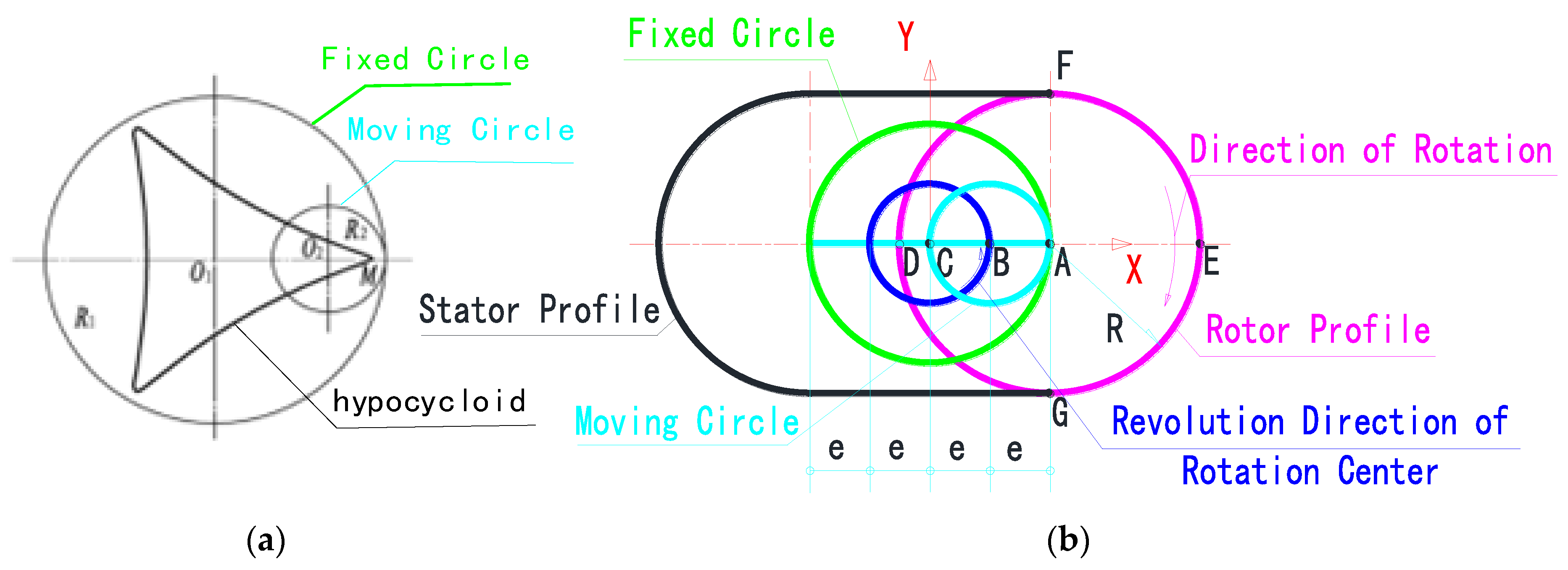
2.1. Working Principle

The internal meshing single-screw device primarily consists of a stator with a spiral cavity, created by rotating the inner surface of an elliptical long hole with a specific pitch, and an eccentrically meshing screw that conjugates with the stator’s profile surface featuring a spiral cavity, as illustrated in Figure 1. In the stator’s cross-section with the spiral cavity, the movement track’s center of the eccentric meshing screw forms a circle’s diameter, traversing a linear distance. This implies that the eccentric screw reciprocates along a straight line between the spiral cavity’s two centers, executing pure rolling within the stator’s spiral cavity. Throughout this process, the material, observed from a cross-sectional perspective, is driven by the eccentric screw to oscillate within the stator’s spiral cavity, undergoing stretching, folding, and rotation within the flow field. Differing from the performance criteria of NETZSCH pumps (Figure 1a), which predominantly emphasize transmission efficiency, the internal meshing screw device (Figure 1b) aims to enhance tensile mixing performance and augment disturbance. To achieve this, flat and spiral sections are alternately arranged on both the internal meshing screw and its corresponding stator. Additionally, the pitch and eccentricity are reduced, gradually decreasing along the axis. The incorporation of spiral and straight sections facilitates material volume deformation during transportation, leading to periodic volume stretching [15].
The meshing stator profile with a spiral cavity and the eccentric screw profile in the internal meshing single-screw device is designed based on the internal cycloid. Generally, when a circle moves within a fixed circle, the trajectory formed by any point M on the moving circle is an end cycloid [33,34], shown in Figure 2a. The radius of the moving circle R 2 is one-third of the radius of the fixed circle R 1 . In a specific scenario, if the radius of the moving circle is half of the radius of the fixed circle, and the point lies on the moving circle’s circumference, the trajectory of the point is the fixed circle’s center diameter. Building upon this principle, any section of the rotor in the axial direction forms a circle of radius. During operation, the rotor’s motion state depicts rotation around center B, which is the rotation center positioned at a distance e eccentricity from the geometric center A, while simultaneously rotating around the stator’s center (also the center of revolution, denoted as center C), maintaining the same eccentricity e from point B. According to hypocycloid theory [35], the rotor’s geometric center A‘s motion state involves rolling along the stator’s linear bone line. Since the rotor’s linear shape is a conjugate curve, resulting in a circular shape in any section, and the stator’s linear shape is formed by two identical semi-circular arcs and two straight lines, its shape remains consistent across sections. The linear shape of the fixed rotor merely rotates to different angles across various sections. The formation principle of the internal meshing screw mixer and stator profile [36] in this paper is depicted in Figure 2.
Figure 3 illustrates the positional diagram of each point at different time intervals during the rotor’s movement. Consistent with Figure 2, the black waist-shaped figure represents the stator, the bright pink circle represents the rotor, the green circle represents the fixed circle, the light blue circle represents the moving circle, and the dark blue circle represents the trajectory formed by the center of the moving circle. As the rotor rotates, it spins at a constant speed in the opposite direction. The rotation center is denoted as point B, and the trajectory of point B is depicted in dark blue, moving counterclockwise around the stator’s geometric center with a radius of e . The turquoise circle represents the moving circle as described in the cycloid formation principle, where points A and C always reside on the diameter of the moving circle, with the circle’s center serving as the rotor’s rotation center. From the figure, it is evident that the rotor not only orbits around the stator’s center but also undergoes rotation at point B, which revolves around the stator’s center at a constant speed in reverse. The trajectory of point A, situated at the rotor’s center, forms a straight line within the stator’s center. Points E and D, as well as F and G, represent points on the same rotor diameter, moving in conjunction with the rotor’s rotation and revolution.
In MATLAB, trajectories of points on the rotor depicted in Figure 2 [37] were plotted, as demonstrated in Figure 4. It is evident that points A and C, both situated on the moving circle, follow linear trajectories dependent on their initial positions. As the center of the rotor, point A moves linearly along the path of the moving circle. Conversely, point C, positioned differently from point A on the moving circle, also traces a linear trajectory, albeit in a different direction due to its distinct initial position. Although point C lies on the moving circle, it does not align with the rotor’s profile, resulting in a linear trajectory. However, due to its off-profile positioning, it does not make direct contact with the fluid. Point B, positioned at the center of the moving circle, undergoes uniform circular motion. Points D and E, located on the same rotor diameter but at different distances from point B, exhibit elliptical motions with different phases. The long axis of the ellipse traced by point D intersects the two centers of the stator profile, while the trajectory of point E‘s ellipse is tangential to the stator profile. Points F and H, corresponding to two points on the same diameter of the rotor, also trace elliptical trajectories symmetrically with respect to the y-axis, internally tangent to the stator profile.

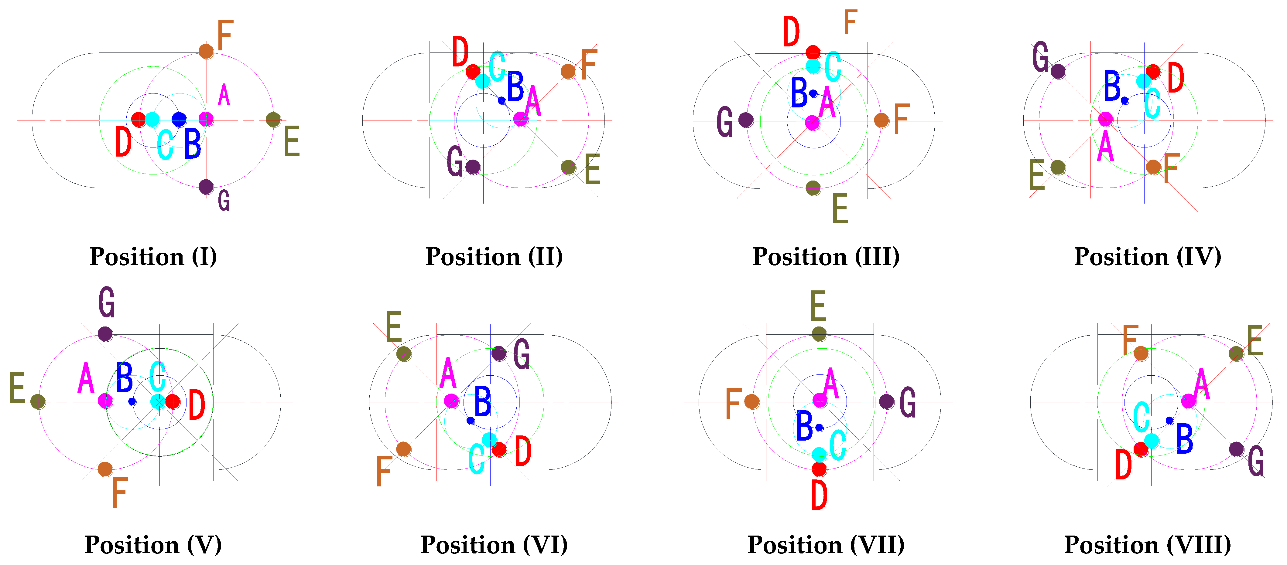
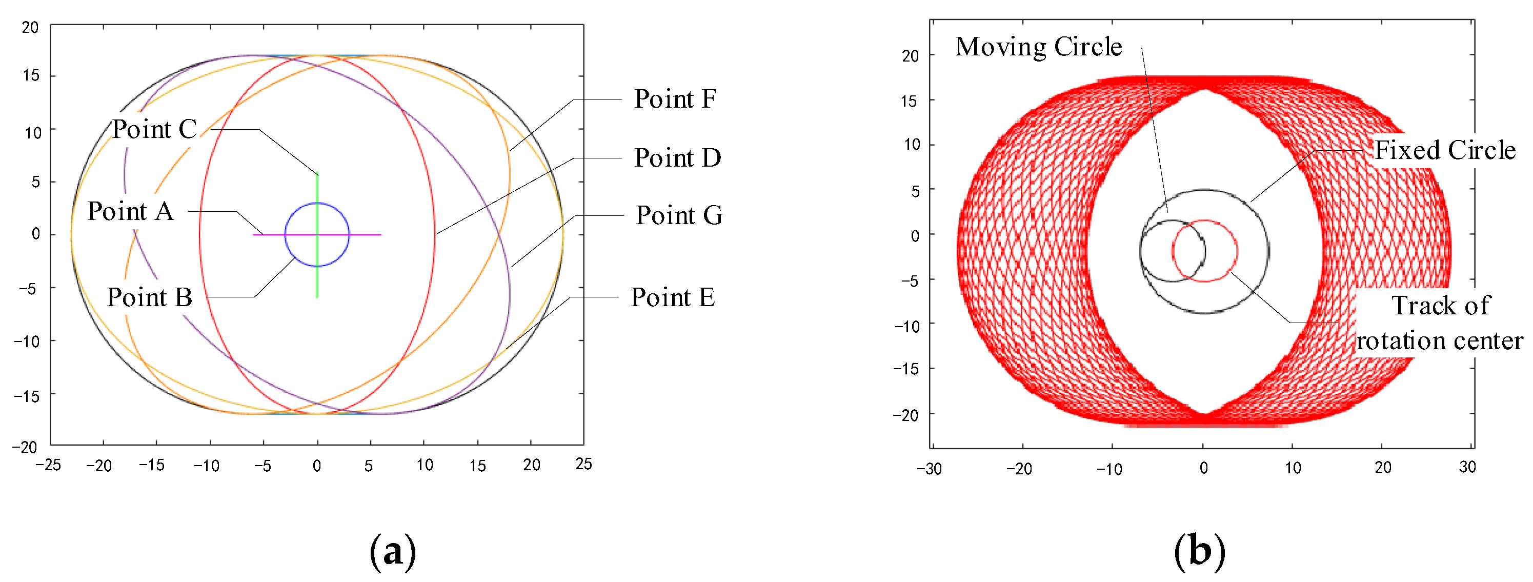
2.2. Kinematic Simulation

To achieve the desired motion based on the epitrochoid principle, a coaxial input-output self-rotation and revolution transmission system was designed. The specific principles are detailed in the referenced literature [38,39]. Figure 5 is the relative position of the stator and rotor and the transmission device. In Figure 5b, the positions corresponding to Figure 2 are marked, where in the cross-section of Figure 2, it is a point, but in the 3D diagram, it becomes an axis. In order to better represent the relationship between the points on the cross-section and the transmission device, analysis is conducted using the straight section as an example. Point A corresponds to the geometric axis of the rotor’s straight section, point B corresponds to the output shaft of the transmission device, and point C corresponds to the center point of the stator and the input shaft of the transmission device. The output shaft (point B) of the transmission device is located between the input shaft (point C) of the transmission device and the geometric axis of the straight section (point A), with a distance of eccentricity e from both.
Using SOLIDWORKS Motion, the kinematic simulation of the internally meshing single-screw system was conducted. The eccentric shaft was designated as the motor, rotating uniformly at a given speed. The trajectories of the output shaft and the single screw were tracked, and the relative positions of the single screw and the helical cavity stator were analyzed. To visualize the motion trajectory of the single screw more intuitively, a reference plane was established on the single screw at every pitch interval starting from the helical surface: I, II, III, IV, V, as shown in Figure 5a.The motion trajectories of the output shaft center and the single-screw center at various cross-sections of the transmission system are depicted in Figure 6. The output shaft trajectory forms a circle with the eccentricity distance as its radius. The internal meshing screw is eccentrically connected to the output shaft (with an eccentricity distance of e ). In this configuration, the center of the single screw lies on the trajectory of the output shaft, as represented by point O 2 in Figure 2. The output shaft undergoes simultaneous revolution and self-rotation in opposite directions at equal speeds, fulfilling the condition for the epitrochoid O 1 to undergo pure rolling within the stator. Consequently, the trajectory of the single-screw center is a straight line, with a distance of 4 e from the center of rotation.
The track length of one revolution of the center of the transmission system output shaft is:
L 1 = 2 e π
At the same time, the single screw in the stator extended distance of 4 e straight reciprocating movement once:
L 2 = 8 e
It can be obtained that the average speed of the center of the output shaft is 2 e π / 8 e = π / 4 of the average speed of the center of the single screw.
The relative position change diagram of the screw and stator during the rotation of the shaft is shown in Table 1. It can be seen that the relative position changes between the screw and the stator with a spiral cavity in each cross-section, the material is transported forward in the cavity formed by the screw and the stator, and the volume changes alternately, forming an extension-dominated flow field.

2.3. Kinematic Mathematical Analysis

The positions of key points on the selected rotor are shown in Figure 2. The X-axis is horizontal and the positive direction is to the right; The Y-axis is vertical, and the positive direction is up. A, B, C, D, E, F, and G are points on the rotor. Point A is the geometrical center of the rotor; Point B is the rotation center of the rotor, point B rotates counterclockwise around the geometric center of the stator, and the rotation radius is: e Point C is the point where the initial position of the rotor coincides with the geometrical center of the stator. Point D is the left intersection of the rotor and the X-axis direction, and point E is the right intersection of the rotor and the X-axis direction. F is the highest point in the vertical direction of the rotor, and G is the lowest point in the vertical direction of the rotor.
The motion equation of point B is:
{ x B = e cos ( π 2 + ω t ) = e sin ω t y B = e sin ( π 2 + ω t ) = e cos ω t
The remaining points rotate clockwise around point B, and their equations of motion are
{ x = x B + L sin ( φ ω t ) y = y B + L cos ( φ ω t )
The distance from this point to point B is denoted as L . φ represents the angle between the line connecting this point and point B and the horizontal coordinate. ω signifies the angular speed of rotation and revolution of the rotor, with counterclockwise rotation being assigned positive values and clockwise rotation assigned negative values. Thus, the rotational angular speed of the rotor is represented by ω for counterclockwise rotation and by − ω for clockwise rotation.
Thus, the equation of motion of each point can be obtained ( e is the radius of revolution, R is the radius of the rotor), shown in Table 2.
Figure 7 illustrates the velocity distribution of different points on the rotor, corresponding to different time instants as depicted in Figure 3. Each point on the rotor rotates clockwise around its center, point B, with a rotational speed equal in magnitude but opposite in direction to the rotation speed of point B around the geometric center of the stator. It is observed that all points exhibit identical velocity cycles, each having a value of π / ω . The rotational center, point B, maintains a constant speed of magnitude e ω . Points A and C, positioned internally on the rotor, trace linear trajectories on the epitrochoid motion circle. Point A moves vertically with the rotor’s geometric center, resulting in zero horizontal velocity, while point C exhibits only horizontal velocity, opposite in trend to point A. At the rotor’s highest point (position I), point A accelerates from zero velocity until reaching its maximum velocity at the midpoint (position III), after which it decelerates until reaching zero velocity at the lowest point (position V). Subsequently, point A reverses direction and accelerates until reaching its maximum velocity at position VII before decreasing back to zero velocity at position I, completing one cycle. The velocity trend of point C is opposite to that of point A, starting from deceleration at position I, reaching zero velocity at position III, then reversing direction and accelerating until reaching maximum velocity at position V. Similar to point A, point C then decelerates and reverses direction until returning to its initial position. At the rotor’s highest point (position I), the rotor starts, and at the midpoint (position III), it reaches maximum velocity before decelerating to zero velocity at the lowest point (position V). Subsequently, point A’s velocity reverses direction, gradually increasing until reaching its maximum at position VII, before decreasing back to zero velocity at position I, completing one cycle. Point C, being internal and situated on the moving circle, also traces a linear trajectory (horizontal line) with a stroke of 4e, zero vertical velocity, and periodic horizontal velocity variations. Point A exhibits only numerical velocity, while point C solely has horizontal velocity, with their velocity trends being inversely related. Points A and C have relatively lower velocities, differing by π / 2 ω in phase. Point A, as the rotor’s geometric center, exhibits the smallest velocity, while points D, E, F, and G, located on the rotor’s surface, exhibit varying velocities. Point D, closest to point B, has the smallest velocity, while point E, farthest from point B, has the highest velocity. Points F and G, equidistant from point B, exhibit equal velocities, differing by π / 2 ω in phase. At the beginning of each cycle, all points have equal absolute velocities.

3. Design of Internal Meshing Screw Mixer

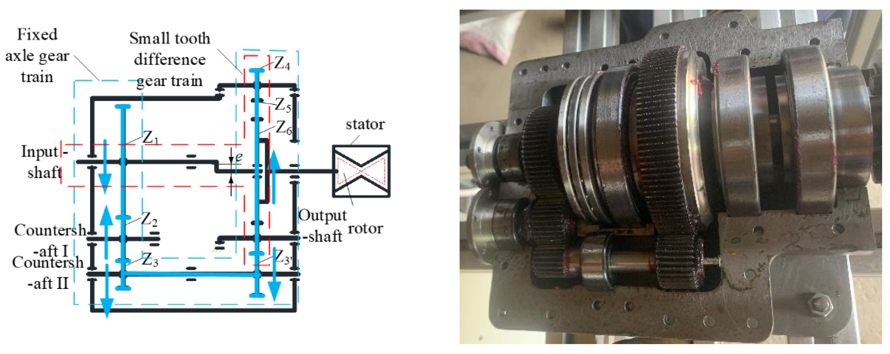
3.1. Transmission Setup

A transmission outputs both a rotation and a revolution while the rotation and the revolution speed are the same. The specific principles are detailed in the referenced literature [38,39]. This enables the provision of the rotational and translational dynamics of the rotor mentioned in Figure 2, thus achieving the desired trajectory. The internal meshing screw mixer transmission system is composed of a K-H-V planetary gear train with a small tooth difference and a fixed shaft gear train (as shown in Figure 8). In order to make the eccentric screw in the stator cavity along a straight line to perform pure rolling, the transmission system needs to output the opposite direction of rotation and rotational speed of the same size planetary motion, due to the eccentricity (that is, the center distance between the planet wheel and the sun wheel) being small, that is, the center distance between the gear Z 5 and the gear Z 6 is small, so the tooth number difference between the gear Z 5 and the gear Z 6 is small. The planetary gear with a small tooth difference is selected as the base gear train. Generally, the sun wheel of the gear train with a small tooth difference is a fixed wheel, and the planetary frame and the planetary wheel constitute the input and output, but the input and output transmission ratio is relatively large in this case, and the fixed axis gear train needs to be designed to adjust the rotation direction and transmission ratio to obtain the rotation and revolution motion in the same speed. Set the input axis as the eccentric axis to drive the gear to perform revolution and the axis on the gear as the output axis. The rotation movement of the output axis is the rotation movement of the gear. The rotation speed of the fixed axis is the same and the direction is opposite.

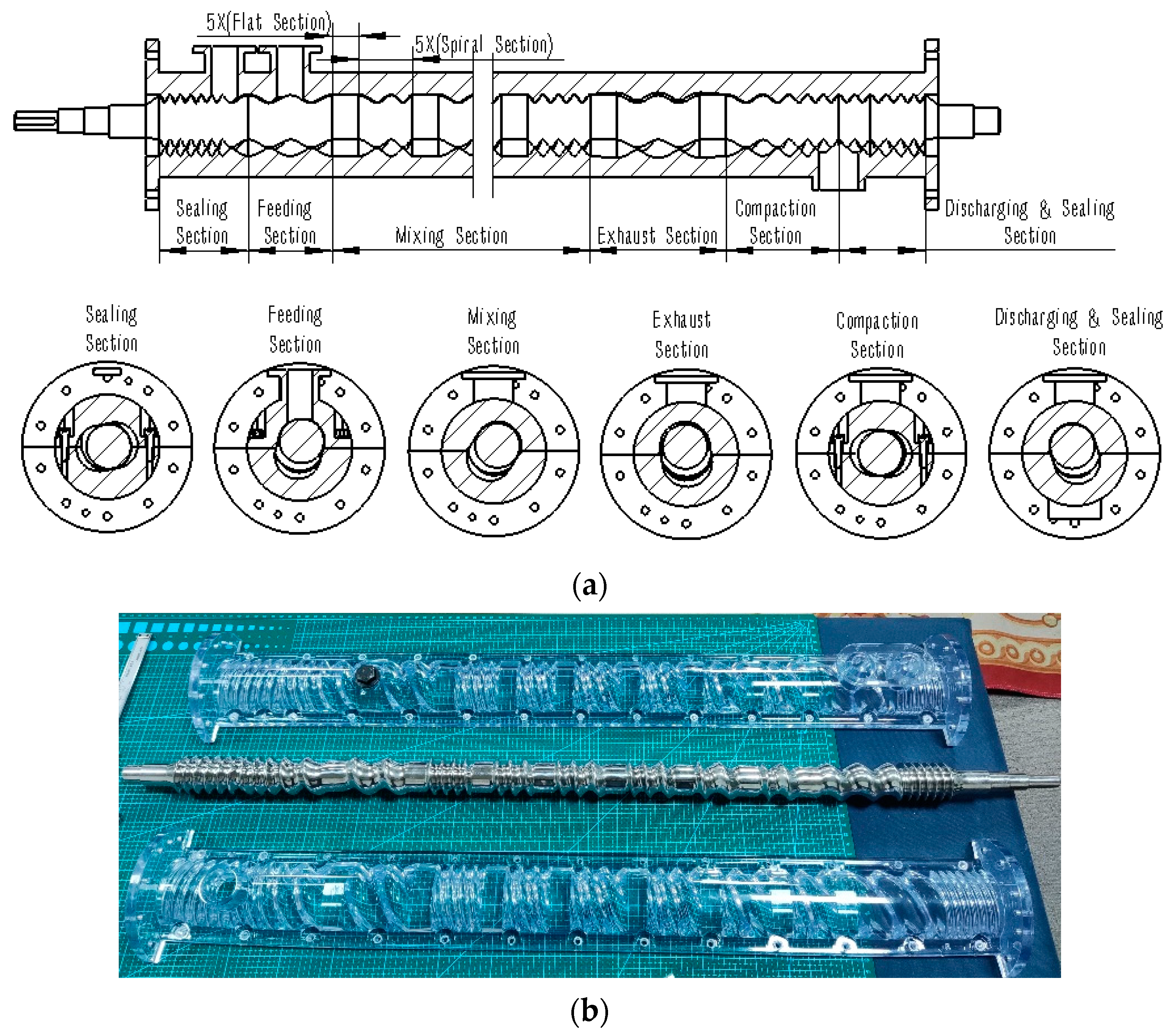
3.2. Internal Meshing Screw Mixer

3.2.1. Stator and Rotor Device of the Internal Meshing Screw Mixer

Most studies focus on extruders in the plastics and rubber industries, where the screw consists of the feed zone, compression zone, melting zone, mixing zone, and extrusion zone. Solid particles are typically fed, so heating devices are generally arranged externally to the stator to provide sufficient temperature to melt the raw material. It is important to emphasize that this study focuses not on an extruder but on a mixing experimental device; therefore, compression, melting, and extrusion zones are not included. Due to the characteristics of the research object (added in gel state, corn syrup), there is no need for a heating device to heat it.
The stator and rotor device of the internal meshing screw mixer is composed of a sealing section, feeding section, mixing section (including five flat sections and five spiral sections), exhaust section, compaction section, and discharging and sealing section [40], shown in Figure 9a. The sealing section comprises forward threads with gradually increasing pitch. The initial small pitch is designed to facilitate sealing, while the progressively increasing pitch is coordinated with the feed section to facilitate material feeding. The feed section consists of threads with larger pitch, enabling rapid forward propulsion of the material into the mixing section. The mixing section includes multiple straight sections and helical sections. The primary purpose of the straight sections is to stretch and mix the material, while the helical sections provide both mixing forces and forward propulsion. The helical and straight sections are alternately arranged, with the pitch of the helical sections gradually decreasing to enhance mixing forces. Subsequently, the exhaust section follows, characterized by a larger gap between the rotor and stator. Prior to the exhaust section, the material is divided into two portions within the channel to achieve stretching and mixing separately. Increasing the gap in the exhaust section allows the two separated material portions to merge, and by adding a vacuum device, air mixed inside can be removed. Following the exhaust section is the compaction section, where the pitch gradually decreases to compact and convey the mixed material to the discharge outlet for discharge. At the discharge outlet, there are reverse threads at both ends, with the first section having a slightly larger pitch to facilitate discharge, while the other section comprises reverse threads with a smaller pitch for sealing purposes. In order to facilitate the visualization test, the stator is made of transparent material SLA3D printing, and the rotor is made of stainless steel 3D printing, shown in Figure 9b.
Figure 10 shows the matching of the rotor and stator at three special positions. Due to the complexity of the rotor profile, the position is marked by the location of the keyway. Position A refers to 0 number of turns in Table 1, position B refers to a 1/4 number of turns, and position C refers to a 1/2 number of turns. It can be seen that the rotor and the stator have a good match, which provides a good basis for mixing.

3.2.2. Sustaining Device for the Rotor of the Internal Meshing Screw Mixer

Since the experimental apparatus in this study is designed for mixing rather than extrusion, there is no need to set up an extrusion zone as in an extruder. Furthermore, due to its high viscosity, without positioning constraints at the end, the entire screw would deviate from its designed position due to excessive torque, as indicated in the previous section. It is evident that the normal operation of this device depends greatly on the accuracy of both position and speed. Therefore, two end support devices are installed. Unlike the setup of one end as the power end and the other end as the extrusion end in an extruder, this experimental setup adopts support at both ends and discharges from the bottom. The purpose of the support devices is to ensure stable operation at the set rotation and revolution speeds.
A sustaining device has been designed for the rotation shaft of the eccentric rotor. The eccentricity of the planetary frame will cause the rotor axis to rotate with an eccentricity of e along the axis of the support device, while the rotor will also rotate along its own axis. It adopts a fixed double-end support mode. This setup utilizes the internal planetary frame of the sustaining device along with bearings to endure the radial and axial forces generated by a portion of the output device axis during rotation. By employing the characteristics of double-end support, the sustaining device aims to minimize deformation of the output device shaft, enhance transmission stability during rotation or revolution, and prevent parts failure or deformation due to reduced bending resistance of the output device shaft. Furthermore, the sealing capability of the sustaining device is also significant. In comparison with traditional sustaining and swing devices, the patented sustaining device can withstand greater axial and radial pressures, offering notable advantages in extending the life of the output device shaft. Figure 11 illustrates the rotation-revolution-sustaining device for the eccentric rotor.

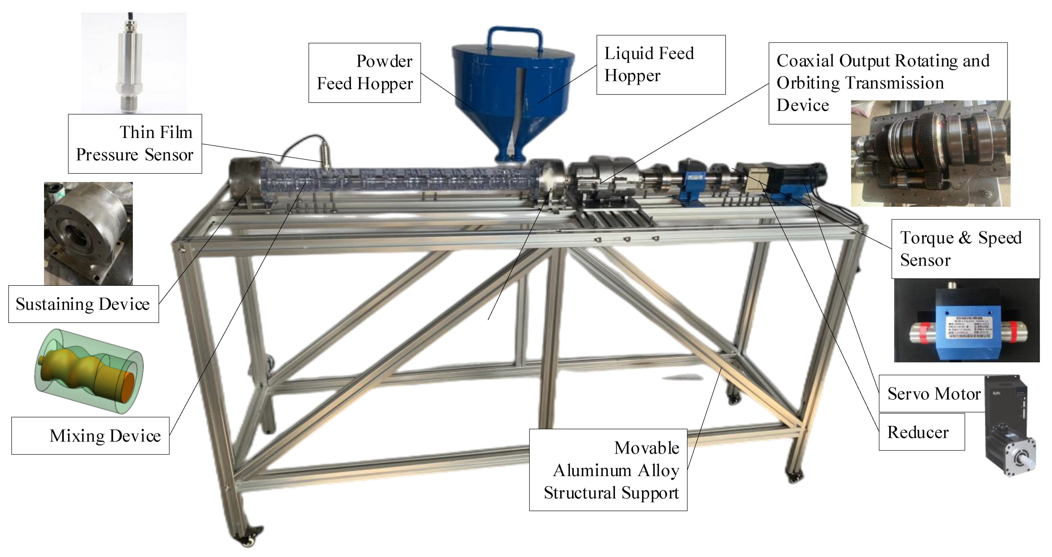
3.3. Overall Structure of the Internal Meshing Screw Mixer

The internal meshing screw mixer (shown in Figure 12), independently researched and developed, comprises a transmission system, a mixed conveying system, a feeding system, a test system, and an integrated control system. To enhance system stability, the screw utilizes a dual fulcrum support and bottom discharge method. Two feed hoppers are installed for accommodating two types of materials—powder and liquid. The experimental system is powered by a servo motor, with speed and rotation angle regulated by a control system. The servo motor is linked to a speed torque sensor via a reducer, with the signal from the sensor feeding into the control system. A coaxial output rotating and orbiting transmission system propels the rotor movement within the stator cavity, as previously described. Thin-film sensors are affixed to the stator for measuring internal cavity pressure. The entire assembly is upheld by an aluminum alloy profile bracket. The testing apparatus enables visualization of the mixing process and facilitates measurement of yield characteristics, torque characteristics, and pressure characteristics during mixing. This paper focuses solely on the mixing characteristics of the internal meshing screw mixing device, with other attributes slated for discussion in subsequent publications.

4. Experimental Verification

4.1. Materials and Methods
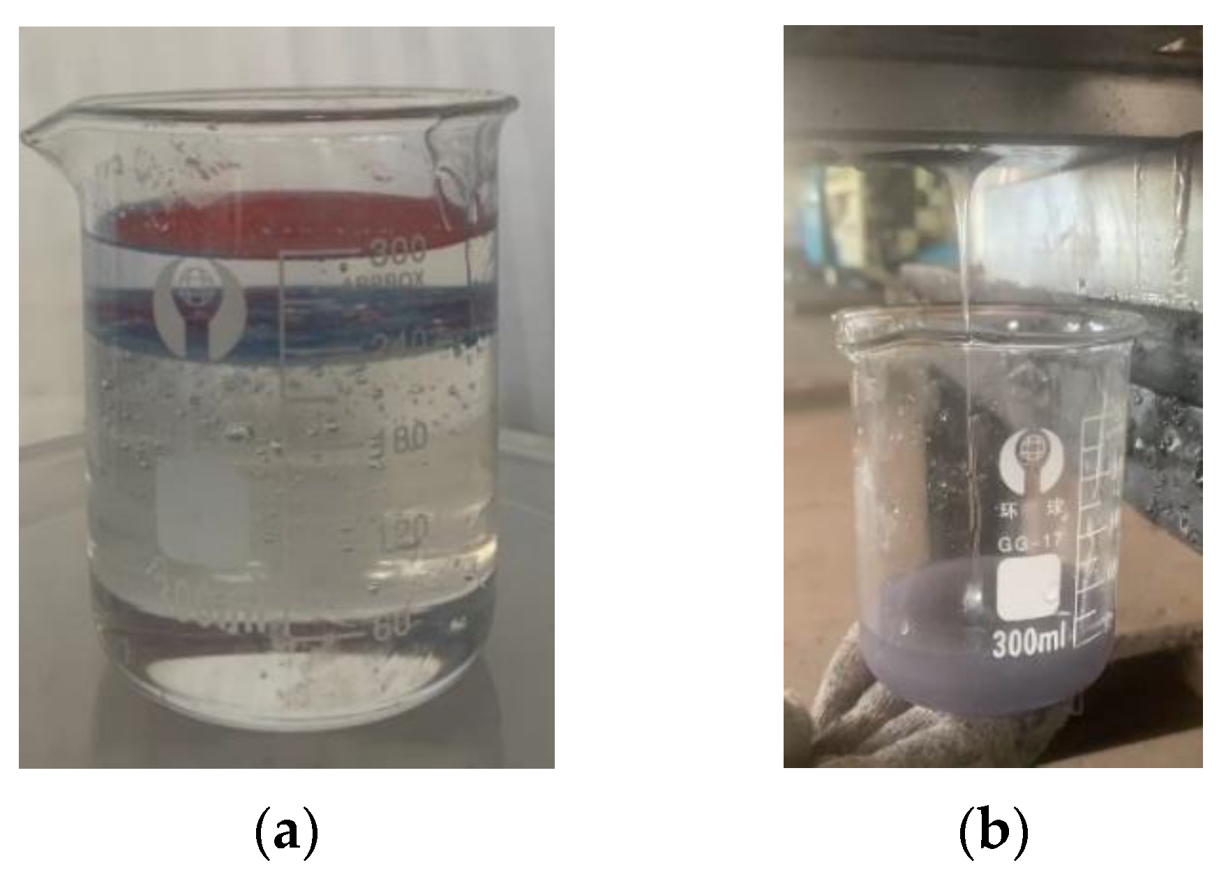
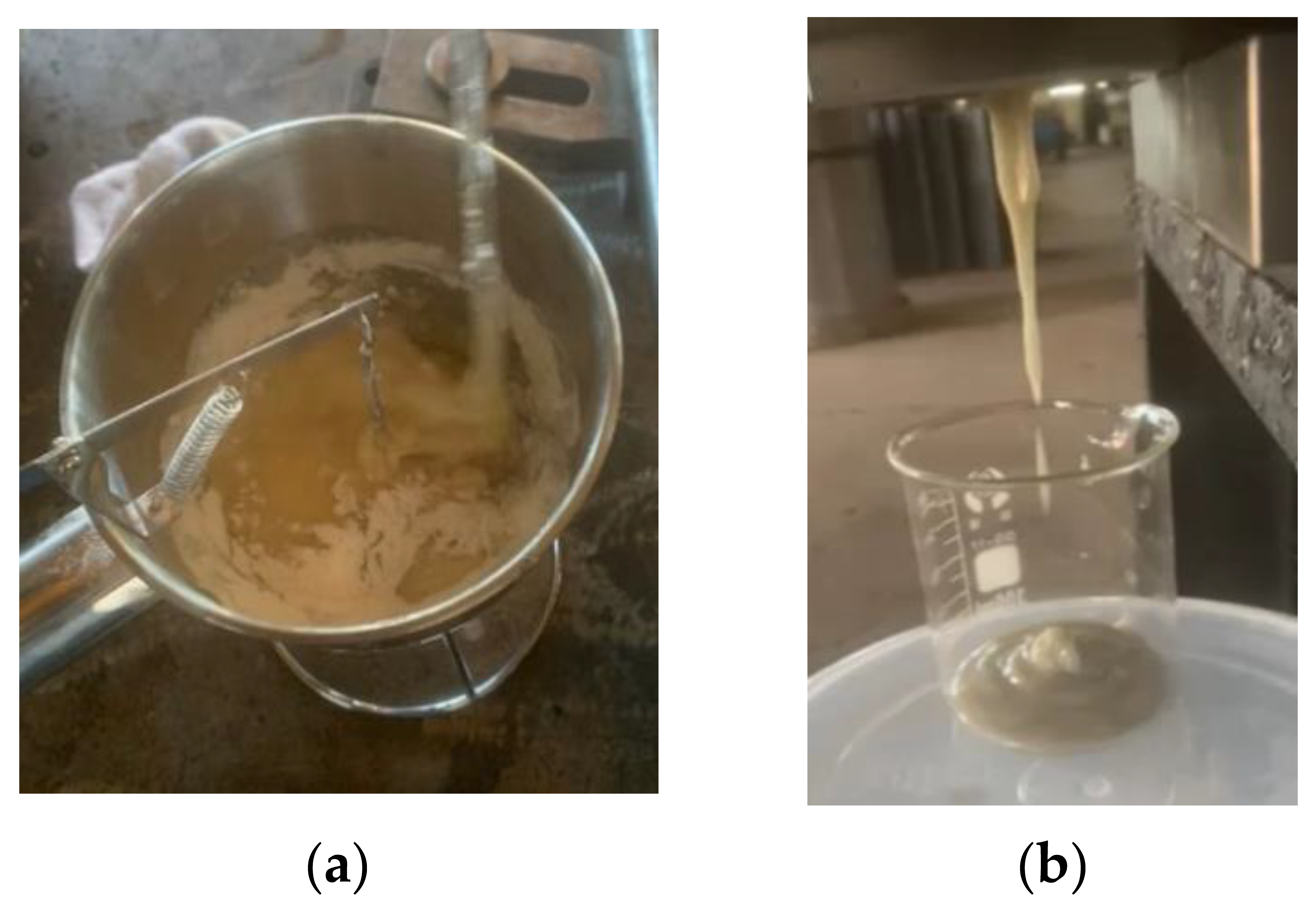
Corn syrup (shown in Figure 13), known for its favorable Newtonian properties and high viscosity, is extensively employed in the food industry. Flour is chosen to mimic the solid constituents in the manufacturing process, while the color of quartz sand facilitates easy observation of the mixing effect. Distilled water serves the purpose of adjusting the viscosity of additional corn syrup and cleaning the tester.
The hydrodynamic traits of the test material stand as crucial factors in ascertaining the mixing efficiency of the extension-dominated mixer. The rheological curve, viscosity, density, and other mechanical parameters serve as a theoretical foundation for designing the extension-dominated mixer. Employ the following instruments to measure the physical properties of the test material. Figure 13b shows an electronic densitometer: MH-300, weighing range: 0.01–300 g, applicable to both liquid and solid samples, accuracy of 0.001 g/cm3, adjustable solution temperature range of 0–100 °C, branded as LICHEN. Utilized for determining material density. Figure 13c shows a rheometer: Anton Paar MCR 102; minimum torque in rotational mode: 0.05 N·m, minimum torque in oscillatory mode: 0.01 N·m, maximum torque: 200 N·m, strain angle range: 0.5 nN·m, angle displacement resolution: 0.01 rad, minimum rotational speed CSS: 10−8 rad/s, minimum rotational speed CSR: 10−8 rad/s, maximum rotational speed CSS/CSR: 314 rad/s, minimum angular frequency: 10−7 rad/s, maximum angular frequency: 628 rad/s, normal force range: 0.01–50 N, branded as Anton, employed for rheological characterization of non-Newtonian fluids. The results are shown in Table 3.
During the experiments, the temperature was maintained at 20 ± 2 °C using air conditioning control. The mixing uniformity of the slurry prepared by the internal meshing screw mixing equipment was tested at various speeds to verify its effectiveness in mixing different liquid and liquid and fine powder combinations. A mixture of corn syrup and distilled water at a ratio of 6:1 was tested to show the mixing effectiveness, adding blue and red quartz sand to make the result more clearly visible (shown in Figure 14). Corn syrup and flour are mixed at a mass ratio of 2:1 to evaluate the mixing effectiveness of the internal meshing screw (shown in Figure 15). Due to feeding system limitations, a higher solid–liquid ratio will cause feeding difficulties).
As a result of the gradual decrease in pitch of the stator and rotor of the internal meshing screw device, the theoretical discharge volume of each is calculated based on the pitch of the rotor at the discharge port (which is the minimum pitch except for the sealing section). Then, the feed is provided proportionally. The formula for calculating the theoretical discharge volume is as follows:
Q m = 8 e R h min ρ ¯ n
Q m represents the theoretical discharge volume. Material feed rates are set proportionally equal to the theoretical discharge volume. e denotes the eccentricity of the internal meshing mixing device. R stands for the radius of the rotor, h min for the minimum pitch of the discharge port, and ρ ¯ for the average density of the slurry mixture. The feed rates of different tests are shown in Table 4.

4.2. Mixing Quality

A mixture of corn syrup and distilled water at a ratio of 6:1 was prepared, and red and blue quartz sand were added to demonstrate the mixing effect. The mixing test was conducted with the equipment set to a rotational speed of 15~55 r/min. Once the equipment stabilized, the aforementioned materials were simultaneously added, and the mixing materials were directly discharged at the discharge port. The color distribution and status of the mixed materials were observed. It was observed that the discharged materials at the discharge port exhibited uniform properties and color distribution, appearing as uniformly purple liquid (as shown in Figure 14).
Use a 5:1 ratio of corn syrup to flour mass (due to feeding system limitations, a higher solid–liquid ratio will cause feeding difficulties). Open the Internal meshing screw mixer to be stabilized, add the material, and test the mixing uniformity at different speeds. At different rotational speeds, the apparent difference of materials after mixing is not large, the mixing uniformity is very good, and there is no powder agglomeration or non-uniformity. The mixing effect is characterized by density uniformity below (as shown in Figure 15). For details, see Section 4.3 Effect of rotational speed on density uniformity in the following.

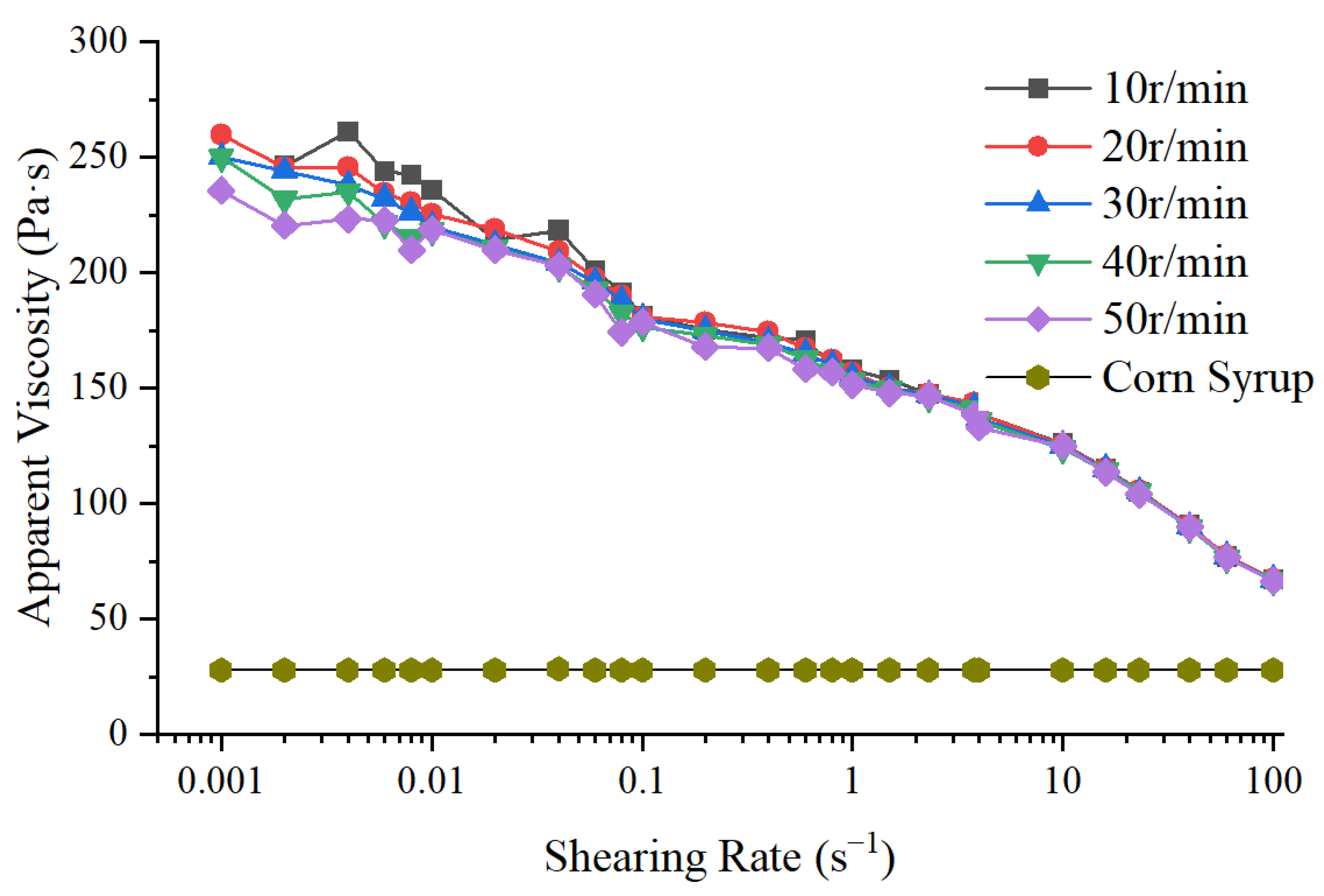
4.3. Rheological Properties of the Slurry

The slurry mixed with the eccentric rotor at various speeds underwent rheometer testing (as depicted in Figure 13c), yielding the apparent viscosity curve of the slurry concerning the shear rate at different speeds, as shown in Figure 16 It is evident that corn syrup displays relatively good Newtonian properties, but it transitions into a non-Newtonian fluid when mixed with flour. The viscosity of the slurry decreases with increasing shear rate, with a more pronounced decrease in viscosity at higher shear rates. The apparent viscosity of the slurry exhibits a consistent trend across different rotational speeds. At low shear rates, corresponding to high-viscosity values, there are noticeable differences in the apparent viscosity of the slurry at different rotational speeds. The maximum apparent viscosity occurs at a rotational speed of 15 r/min, while the minimum apparent viscosity occurs at 55 r/min. However, under the same shear rate conditions, the average apparent viscosity decreases consistently as the rotational speed increases, albeit the differences are generally minimal.
Figure 16 shows the rheological characteristics of slurry at different rotational speeds. The slurries are pseudoplastic fluids in non-Newtonian fluids, and the apparent viscosity η of the slurry is represented by a power law model as follows:
η = k γ ˙ n 1
where n refers to the non-Newtonian fluid index, k refers to the consistency coefficient, and refers to the shear strain rate, which is defined as follows:
γ ˙ = 2 ( D : D )
As can be seen from the above formula, when n < 1 , the apparent viscosity decreases with the increase of shear strain rate, and the power law fluid becomes shear thinner. When n > 1 , the apparent viscosity increases with the increase of shear strain rate, and the power law fluid appears to be shear thickened.
The non-Newtonian fluid index varies little at different speeds and fluctuates in the range of 1%, while the consistency coefficient fluctuates greatly at about 5% (shown in Table 5). In general, the power law characteristics of the slurry at different speeds are similar, and the difference is not large. The fitted R-square value is greater than 0.9 except that 55 r·/min is slightly smaller.

4.4. Mixing Uniformity of the Slurry

During the experiment, the machine is first started and allowed to run smoothly. Material is then added according to the proportions. After the readings of the torque, pressure sensors, etc., stabilize, samples of 30 mL are taken every 1 min for measurement (the beaker provided with the electronic density meter has a capacity of 50 mL). The prepared mixture was sampled at various rotational speeds to obtain a significant number of density samples of the slurry mixture. The test results included the simulated slurry mixture density for each group, along with the mean value and standard deviation of the density for each group (as depicted in Table 6). Additionally, the relationship between the average density of the simulated slurry mixture and the change in rotor speed was illustrated (as shown in Table 6).
Through comparative analysis of the density values of slurry mixtures in each group, as presented in Table 6, it is observed that the mixture density of propellant simulants fluctuates to a certain extent at different rotational speeds, albeit the fluctuation is not significant. Specifically, at rotational speeds of 15 r/min, 25 r/min, 35 r/min, 45 r/min, and 55 r/min, the average densities were recorded as 1.197 g/cm3, 1.199 g/cm3, 1.206 g/cm3, 1.207 g/cm3, and 1.202 g/cm3, respectively. The minimum standard deviation is 0.0082, and the maximum standard deviation is 0.0130. It can be deduced that the distribution density uniformity exceeds 90% (standard deviation is less than 0.1), indicating that the internal meshing screw mixer exhibited excellent efficiency in the mixing process between high-viscosity fluid and fine powder, to demonstrate the feasibility of applying the intermeshing screw mixing device in the food industry and the correctness of this design method.
Using the mixing uniformity index to quantify the mixing effect of the slurry is defined as the ratio of the bulk density of the powdered material in the mixed slurry to the standard deviation of the mixture prepared by the intermeshing screw. The higher the mixing uniformity index, according to its definition, the greater the mixing uniformity. The calculation formula for the mixing uniformity index is as follows [41]:
I = ρ 0 10 s
where I represents the mixing uniformity index; ρ 0 is the bulk density of the powdered material, which, in this case, is the bulk density of flour since the powdered material in the slurry is flour; and s is the standard deviation of the density of the slurry after mixing, and the unit of bulk density of the powdered material is consistent with the unit of standard deviation of slurry density.
The average speed, distribution, and mixing uniformity index for different speeds are presented in Figure 17. It can be observed that the density of the slurry varies little at different speeds. The mixing uniformity index gradually decreases with increasing speed, reaching its maximum at 15 r/min. The overall trend of the mixing uniformity index decreases with increasing speed, indicating a deterioration in density uniformity. A peak appears at 45 r/min, which may be due to the maximum values of elongation rate and shear rate at this speed (see simulation analysis in reference [37]). As the speed increases, the residence time of the material in the mixer decreases, which may be the main reason for the decrease in mixing uniformity. Of course, the variation in speed also brings about changes in pressure inside the mixing chamber, rotational torque, power, tensile stress, shear stress, and leakage. In the later stages, a combination of theoretical analysis and application of the experimental device is needed to analyze the effects of mixing under different parameter conditions by studying the mixing mechanism of high-viscosity fluid inside the intermeshing screw.

5. Conclusions

This study introduces a design method for an internal meshing screw mixer based on kinematic principles. The mixer features a helical cavity formed by alternating volumes of the stator and rotor, creating an environment primarily dominated by extension for mixing high-viscosity fluids. A kinematic model based on the trochoidal principle is established to track the trajectory and equations of key points on the rotor, simulating its rotation and revolution processes and capturing the velocity variations at various points. Utilizing the results of kinematic analysis, a design for the stator and rotor is developed based on relevant functional divisions. To achieve the desired motion effects, transmission and support devices are designed, and the relationship between the transmission device and the trochoidal profile of the fixed rotor is established.
The designed internal meshing screw mixer is manufactured and tested, demonstrating the smooth operation of the rotor within the stator according to the predetermined motion laws. The mixer’s application in the food industry is validated through experiments with corn syrup and flour, showing its effectiveness in mixing both high-viscosity fluids and fine powders. Samples are taken from slurries prepared by the eccentric rotor mixer at different speeds. Slurry viscosity was tested with a rheometer at different speeds with an eccentric rotor mixer. Results showed that viscosity decreased with increasing shear rate, with a more pronounced decrease at higher shear rates. The apparent viscosity trend remained consistent at different speeds, although variations were observed at lower shear rates, especially concerning speed. The non-Newtonian fluid index exhibited minimal variations at different speeds, while the consistency coefficient showed significant fluctuations. Additionally, the mixing uniformity index of slurry is utilized to evaluate the uniformity and dispersion of this expanded mixer. At different speeds, the density of the slurry remains relatively stable. The mixing uniformity index gradually decreases with increasing speed, reaching its maximum at 15 r/min. There is an overall decreasing trend in the mixing uniformity index with increasing speed, indicating a decline in density uniformity. A peak is observed at 45 r/min, possibly due to the occurrence of maximum values of elongation rate and shear rate at this speed. As the speed increases, the residence time of the material in the mixer decreases, which may be the primary reason for the decrease in mixing uniformity.
In this study, we propose a trochoidal-based design method for internal meshing screw mixers and demonstrate its preliminary application in the food industry. Our experimental results suggest promising prospects for this design method in high-viscosity mixing processes in the food industry. Future research will focus on further optimizing feeding devices, expanding the range of test materials, and investigating the influence of internal meshing screws on the mixing mechanism of high-viscosity fluid mixers, the variation in speed affects parameters such as pressure inside the mixing chamber, rotational torque, power, tensile stress, shear stress, and leakage. Therefore, in the later stages, a combination of theoretical analysis and application of the experimental device is required to analyze the impact of different parameter conditions on mixing effectiveness by studying the mixing mechanism of high-viscosity fluid inside the intermeshing screw. These efforts will contribute to advancing the application of internal meshing screw mixers in the food industry and providing new insights and methods for related fields.

Author Contributions

Validation, Y.M.; Investigation, G.L. and Z.H.; Resources, N.L.; Data curation, Y.H.; Writing—original draft, F.G.; Writing—review & editing, G.W.; Supervision, X.L. All authors have read and agreed to the published version of the manuscript.

Funding

This research was funded by National Natural Science Foundation of China, grant number 32060414; Inner Mongolia Natural Science Foundation, grant number 2023QN05034; 2022MS06023; Inner Mongolia Natural Science Foundation of the Autonomous Region military-civilian integration key research, grant number JMZD202201; Key research and development and achievement transformation plan of Inner Mongolia Autonomous Region, grant number 2023YFDZ0006; Hohhot Science and Technology Plan Project, grant number 2023-Gao-6.

Institutional Review Board Statement

Not applicable.

Informed Consent Statement

Not applicable.

Data Availability Statement

The data presented in this study are available in the article.

Conflicts of Interest

The authors declare no conflict of interest.

References

  1. Zhan, X.; Yu, L.; Jiang, Y.; Jiang, Q.; Shi, T. Mixing Characteristics and Parameter Effects On the Mixing Efficiency of High-Viscosity Solid–Liquid Mixtures Under High-Intensity Acoustic Vibration. Processes 2023, 11, 2367. [Google Scholar] [CrossRef]
  2. Peddireddy, K.R.; Clairmont, R.; Robertson-Anderson, R.M. Polymer Threadings and Rigidity Dictate the Viscoelasticity of Entangled Ring-Linear Blends and their Composites with Rigid Rod Microtubules. J. Rheol. 2023, 67, 125–138. [Google Scholar] [CrossRef]
  3. Wang, F.; Wu, Z.; Shangguan, X.; Sun, Y.; Feng, J.; Li, Z.; Chen, L.; Zuo, S.; Zhuo, R.; Yan, P. Preparation of Mono-Dispersed, High Energy Release, Core/Shell Structure Al Nanopowders and their Application in Htpb Propellant as Combustion Enhancers. Sci. Rep. 2017, 7, 5228. [Google Scholar] [CrossRef]
  4. Li, J.; Lu, B.; Wang, C.-Q.; Bai, X.-X.; Sun, M.-J. Experimental study on mixing properties in ultrasonic wave. Food Mach. 2012, 28, 134–138. [Google Scholar]
  5. Kim, N.; Lee, J. Optimum Shape and Process Design of Single Equipment for its Mixing Performance Using Finite Volume Method. Korea-Austrilia Rheol. J. 2009, 4, 289–297. [Google Scholar]
  6. Anderson, P.D.; Galaktionov, O.S.; Peters, G.W.M.; Meijer, H.E.H.; Iii, C.L.T. Material Stretching in Laminar Mixing Flows: Extended Mapping Technique Applied to the Journal Bearing Flow. Int. J. Numer. Methods Fluids 2002, 40, 189–196. [Google Scholar] [CrossRef]
  7. Yuan, Z.; Chen, X.; Yu, D. Recent Advances in Elongational Flow Dominated Polymer Processing Technologies. Polymers 2021, 13, 1792. [Google Scholar] [CrossRef]
  8. Li, F.Q.; He, L.L. Effects of chain stiffness and shear flow on nanorod distribution and orientation in polymer melts. J. Zhejiang Univ. (Sci. Ed.) 2021, 48, 694–699. [Google Scholar]
  9. Huang, L.; Ou, X.L.; Wu, S.J. Effect of Elongation Flow Field on Dispersion Mixing of Filled Polymer. China Plast. 2006, 20, 53–58. [Google Scholar]
  10. Bauer, H.; Khinast, J. Detecting Mixing Barriers in Twin-Screw Extruder Elements Via Lagrangian Coherent Structures. Chem. Eng. Sci. 2022, 263, 118069. [Google Scholar] [CrossRef]
  11. Pandey, V.; Maia, J.M. Comparative Computational Analysis of Dispersive Mixing in Extension-Dominated Mixers for Single-Screw Extruders. Polym. Eng. Sci. 2020, 60, 2390–2402. [Google Scholar] [CrossRef]
  12. Netzsch Pump Industry Lanzhou Co., Ltd. Centennial NETZSCH Pioneer in Pump Industry. Gen. Mach. 2008, 10, 44–45. [Google Scholar]
  13. Ju, J.P.; Zhang, G.Z.; Yin, X.C. An Eccentric Rotor Volume Pulsation Deformation Plasticizing Transportation Method and Device. CN104002447A, 15 May 2014. [Google Scholar]
  14. Qin, S.; He, H.; Zhang, T.; Huang, Z.; Qu, J. Study on volume-pulsation injection-molding technology for plastics. China Plast. 2023, 37, 96–101. [Google Scholar]
  15. Qu, J.; Wu, T. Advanced processing technology of polymer materials helps material innovation and development. Sci. Technol. Rev. 2020, 38, 54–62. [Google Scholar]
  16. Zhu, C.; Hao, Y.; Wu, H.; Chen, M.; Quan, B.; Liu, S.; Hu, X.; Liu, S.; Ji, Q.; Lu, X.; et al. Self-Assembly of Binderless Mxene Aerogel for Multiple-Scenario and Responsive Phase Change Composites with Ultrahigh Thermal Energy Storage Density and Exceptional Electromagnetic Interference Shielding. Nano-Micro Lett. 2024, 16, 57. [Google Scholar] [CrossRef]
  17. Li, X.; Liu, Z.; Liu, Z.; Li, Y.; Tang, L.; Zhang, W.; Lu, X.; Li, Y.; Niu, R.; Qu, J. High Transparency, Degradable and Uv-Protective Poly(Lactic Acid) Composites Based On Elongational Rheology and Chain Extender Assisted Melt Blending. Int. J. Biol. Macromol. 2024, 256, 128469. [Google Scholar] [CrossRef] [PubMed]
  18. Chen, L.; Feng, K.; Zhang, X.; Gong, J.; Qu, J.; Niu, R. Ion-Exchange Enabled Dual-Functional Swarms with Reconfigurability and Magnetic Controllability. Small 2024, 4, 2308318. [Google Scholar] [CrossRef]
  19. Liu, Z.; Gong, Z.; Li, X.; Ren, J.; Gong, J.; Qu, J.; Niu, R. Mass Production of Biodegradable Porous Foam for Simultaneous Solar Evaporation and Thermoelectricity Generation. J. Mater. Chem. A 2023, 11, 26784–26793. [Google Scholar] [CrossRef]
  20. Liu, S.; Sheng, M.; Quan, B.; Yang, Y.; Ji, Q.; Hu, X.; Lu, X.; Qu, J. In Situ Mil-101 Growth On Cotton Cloth to Fabricate Multifunctional Phase Change Composites Driven by Solar and Magneto-Thermal for All-Day Desalination. J. Colloid Interface Sci. 2024, 659, 905–913. [Google Scholar] [CrossRef]
  21. Ji, Q.; Sheng, X.; Li, X.; Liu, S.; Chen, Q.; Guo, P.; Yang, Y.; Huang, Y.; Zhang, G.; Lu, X.; et al. Camel Skin-Fat Structure Inspired Mxene@Pva/Pcc Aerogel Composite for Efficient Medium and Low Temperature Infrared Stealth. Chem. Eng. J. 2023, 476, 146671. [Google Scholar] [CrossRef]
  22. Yang, Y.; Liu, S.; Jin, L.; Li, G.; Quan, B.; Chen, Q.; Tang, X.; Ji, X.; Wu, H.; Lu, X.; et al. A Novel Multisource Energy Harvester with Enhanced Thermal Conductivity for Efficient Energy Harvesting and Superior Emi Shielding. Compos. Part A—Appl. Sci. Manuf. 2023, 175, 107803. [Google Scholar] [CrossRef]
  23. Du, Y.; Wu, T.; Zhou, W.; Li, C.; Ding, C.; Chen, P.; Xie, H.; Qu, J. Cicada Wing-Inspired Transparent Polystyrene Film Integrating Self-Cleaning, Antifogging, and Antibacterial Properties. ACS Appl. Mater. Interfaces 2023, 15, 46538–46549. [Google Scholar] [CrossRef] [PubMed]
  24. Feng, K.; Shen, W.; Chen, L.; Gong, J.; Palberg, T.; Qu, J.; Niu, R. Weak Ion-Exchange Based Magnetic Swarm for Targeted Drug Delivery and Chemotherapy. Small 2023, 20, e2306798. [Google Scholar] [CrossRef] [PubMed]
  25. Hu, X.; Huang, X.; Quan, B.; Zhu, C.; Yang, Y.; Sheng, M.; Ding, C.; Wen, H.; Li, X.; Wei, J.; et al. Tree-Inspired and Scalable High Thermal Conductivity Ethylene-Vinyl Acetate Copolymer/Expanded Graphite/Paraffin Wax Phase Change Composites for Efficient Thermal Management. Chem. Eng. J. 2023, 471, 144720. [Google Scholar] [CrossRef]
  26. Hu, X.; Quan, B.; Ai, B.; Sheng, M.; Liu, S.; Huang, X.; Wu, H.; Lu, X.; Qu, J. Engineering Asymmetric Multifunctional Phase Change Composites for Improved Electromagnetic Interference Shielding and Wireless Personal Thermal Therapy. J. Mater. Chem. A 2023, 11, 16138–16152. [Google Scholar] [CrossRef]
  27. Tang, W. The Virtual Prototype Construction and the Dynamics Study Visualization of Screw Pump. Sci. Technol. Vis. 2012, 13, 185–186. [Google Scholar]
  28. Ni, Y.; Wu, J.; Guo, H. Parameter Modeling and Kinematical Simulation for Rotor and Stator of Screw Pump. J. Donghua Univ. (Eng. Ed.) 2013, 30, 38–43. [Google Scholar]
  29. Wang, Z. The Virtual Assembly Simulation and Optimization Design On Single Screw Pump of Offshore Petroleum Well Cementing Lads Device. Adv. Mater. Res. 2014, 945–949, 203–208. [Google Scholar] [CrossRef]
  30. Hu, J. Extrusion Process and Characteristics Study of Polyethylene on Eccentric Rotor Extruder. Master’s Thesis, South China University of Technology, Guangzhou, China, 2016. [Google Scholar]
  31. Chen, R.Y. Study on Mixing Mechanism and Structural Properties of Nano-Filling Composites via Volume Elongation Deformation. Ph.D. Thesis, South China University of Technology, Guangzhou, China, 2016. [Google Scholar]
  32. Yuan, D. Stuty on Elongational Deformation Effects of the Melt Conveying in an Eccentric Rotor Extruder. Ph.D. Thesis, South China University of Technology, Guangzhou, China, 2018. [Google Scholar]
  33. Wen, J.S.; Yin, C.H.; Fu, Y.; Hu, Z.G. Numerical investigations of energy consumption in the melt conveying section of an eccentric rotor extruder at different rotation rates. China Plast. Ind. 2017, 45, 51–54. [Google Scholar]
  34. Wu, T.; Yuan, D.; Qiu, F.; Chen, R.; Zhang, G.; Qu, J. Polypropylene/Polystyrene/Clay Blends Prepared by an Innovative Eccentric Rotor Extruder Based on Continuous Elongational Flow: Analysis of Morphology, Rheology Property, and Crystallization Behavior. Polym. Test. 2017, 63, 73–83. [Google Scholar] [CrossRef]
  35. Luo, S.; Mo, J. Manufacturing and Contact Characteristics Analysis of a Novel 2K-H Internal Meshing Planetary Reducer with Involute-Cycloid Combined Tooth Profiles. Proc. Inst. Mech. Eng. Part C-J. Eng. Mech. Eng. Sci. 2024, 5, 09544062241228380. [Google Scholar] [CrossRef]
  36. Hao, Y.; Guo, F.; Wu, G.; Hou, Z.; Li, N.; Liu, G.; Cui, X.; Meng, D.; Li, Y.; Li, X. Numerical Simulation and Experimental Research On Heat Transfer Characteristics Based On Internal Meshing Screw. Appl. Sci. 2024, 14, 220. [Google Scholar] [CrossRef]
  37. Fan, D.; Yang, M.; Huang, Z.; Wen, J. Numerical Simulation of Mixing Characteristics in the Eccentric Rotor Extruder with Different Process Conditons and Structure Parameters. Adv. Polym. Technol. 2019, 56, 395–408. [Google Scholar]
  38. Ju, J.P.; Zhang, G.Z. A Transmission Method and Device for Coaxial Output Rotation and Revolution. CN 105065582 A, 13 July 2015. [Google Scholar]
  39. Li, H.C.; Guo, F. Optimal Design of Parameters of Coaxial Output Rotation and Revolution Transmission System. Chem. Eng. Equip. 2023, 1, 158–160. [Google Scholar]
  40. Guo, F.; Ma, Y.; Meng, Y.H.; Hao, Y.H.; Liu, X.L.; Wang, Z.; Wu, G.F.; Li, X.W. The Utility Model Relates to a Single-Screw Continuous Mixing Device for High Viscosity Materials. CN 219128925U, 8 December 2022. [Google Scholar]
  41. Wu, H. Study on Continuous Mixing Technology and Its Mechanism of Solid Propellant Simulation Slurry Dominated by Elongational Deformation. Ph.D. Thesis, South China University of Technology, Guangzhou, China, 2020. [Google Scholar]
Figure 1. Internal meshing screw (eccentric rotor) structure: (a) The structure of the NETZSCH pump screw; (b) The structure of internal meshing screw mixer; (c) The stator and the rotors with different cross-sections.
Applsci 14 04119 g001
Figure 2. (a) Formation principle of internal cycloid; (b) Formation principle of Internal meshing screw mixer and stator profile.
Applsci 14 04119 g002
Figure 3. The position diagram of each point at different times when the rotor is moving.
Applsci 14 04119 g003
Figure 4. The trajectory of each point of the rotor in motion: (a) Motion trajectory of special points of rotor (b) Motion trace assembly at each point on the rotor.
Applsci 14 04119 g004
Figure 5. Relative position of stator and rotor and transmission device: (a) Axonometric drawing; (b) Cut way drawing. I, II, III, IV, V: the helical surface; A, B, C, D, E correspond to the points in Figure 2b. e is the eccentric distance.
Applsci 14 04119 g005
Figure 6. The trajectory of the transmission system output shaft and the center of the single screw in each section: (a) Output axis center trajectory; (b) I-I Central trajectory; (c) II-II Central trajectory; (d) III-III Central trajectory; (e) IV-IV Central trajectory; (f) V-V Central trajectory.
Applsci 14 04119 g006
Figure 7. The speed of each point of the rotor in motion: (a) Horizontal velocity; (b) Vertical velocity; (c) Velocity.
Applsci 14 04119 g007
Figure 8. Internal meshing screw mixer drive system. The blue arrow represents the direction of rotation of the gear.
Applsci 14 04119 g008
Figure 9. Stators and rotors for mixing: (a) Rotor diagram and sectorization; (b) Rotor and stators of mixer made by 3D printing.
Applsci 14 04119 g009
Figure 10. Matching of rotor and stator at three special positions: (a) Position A; (b) Position B; (c) Position C.
Applsci 14 04119 g010
Figure 11. Sustaining device for rotation shaft of eccentric rotor.
Applsci 14 04119 g011
Figure 12. Design and Implementation of the Experimental Apparatus.
Applsci 14 04119 g012
Figure 13. Test Material: (a) Test Material; (b) Electron densitometer; (c) Anton Paar MCR 102 rheometer.
Applsci 14 04119 g013
Figure 14. Display of mixing effect of liquid–liquid system: (a) Material status before mixing; (b) State of the material after mixing.
Applsci 14 04119 g014
Figure 15. Display of mixing effect of solid–liquid system: (a) Material status before mixing; (b) State of the material after mixing.
Applsci 14 04119 g015
Figure 16. Slurry viscosity curve with shear rate at different rotation speeds.
Applsci 14 04119 g016
Figure 17. Relation between speed variation and mean density and mixing uniformity index of slurry.
Applsci 14 04119 g017
Table 1. Change of relative positions of screw and stator after output shaft revolution.
Number of TurnsLongitudinal SectionCross-Section Diagram
IIIIIIIV
0Applsci 14 04119 i001Applsci 14 04119 i002Applsci 14 04119 i003Applsci 14 04119 i004Applsci 14 04119 i005Applsci 14 04119 i006
1/4Applsci 14 04119 i007Applsci 14 04119 i008Applsci 14 04119 i009Applsci 14 04119 i010Applsci 14 04119 i011Applsci 14 04119 i012
1/2Applsci 14 04119 i013Applsci 14 04119 i014Applsci 14 04119 i015Applsci 14 04119 i016Applsci 14 04119 i017Applsci 14 04119 i018
3/4Applsci 14 04119 i019Applsci 14 04119 i020Applsci 14 04119 i021Applsci 14 04119 i022Applsci 14 04119 i023Applsci 14 04119 i024
1Applsci 14 04119 i025Applsci 14 04119 i026Applsci 14 04119 i027Applsci 14 04119 i028Applsci 14 04119 i029Applsci 14 04119 i030
Table 2. Trajectory equation and velocity equation of each point on rotor.
PointParameter ValueTrajectory EquationVelocity Equation
B-- x B = e sin ω t
y B = e cos ω t
V x B = e ω cos ω t
V y B = e ω sin ω t
A L A B = e
φ B A = π 2
x A = 0
y A = 2 e cos ω t
V x A = 0
V y A = 2 e ω sin ω t
C L B C = e
φ B C = π 2
x C = 2 e sin ω t
y C = 0
V x C = 2 e ω cos ω t
V y C = 0
D L B D = R e
φ B D = π 2
x D = R sin ω t
y D = ( 2 e R ) cos ω t
V x D = R ω cos ω t
V y D = ( R 2 e ) ω sin ω t
E L B E = R + e
φ B E = π 2
x E = R sin ω t
y E = ( R + 2 e ) cos ω t
V x E = R ω cos ω t
V y E = ( R + 2 e ) ω sin ω t
F L B F = e 2 + R 2
φ B F = π 2 + arctan R e
x F = e sin ω t L B F sin ( φ B F ω t )
y F = e cos w t + L B F cos ( φ B F ω t )
V x F = e ω cos ω t + ω L B F cos ( φ B F ω t )
V y F = e ω sin ω t + ω L B F sin ( φ B F ω t )
G L B G = e 2 + R 2
φ B G = arctan e R
x G = e sin ω t + L B G cos ( φ B G ω t )
y G = e cos ω t + L B G sin ( φ B G ω t )
V x G = e ω cos ω t + ω L B G cos ( φ B G ω t )
V y G = e ω sin ω t ω L B G cos ( φ B G ω t )
Table 3. Physical properties of the test material.
Material NamePhysical Properties and Parameters
Corn syrupCorn syrup, thick transparent liquid, Deen Food Ingredients Co., LTD., density of 1340 kg·m−3, viscosity (28 ± 0.19) Pa·s (20 °C), transmittal rate of 98.2%.
Flour powderWhite powder, density 520 kg·m−3, particle size 140 mesh (106 μm).
Table 4. Feed rate of different tests.
Rotate Speed/(r·min−1)1525354555
Corn syrup and water
Feed rate of corn syrup/(g min−1)73125170220270
Feed rate of water/(g min−1)1525344454
Corn syrup and flour powder
Feed rate of corn syrup/(g min−1)3048607896
Feed rate of flour powder/(g min−1)58101316
Table 5. Rheological parameters of slurry at different rotational speeds.
Rotational Speed/r·min−1Slurry (2:1 Ratio of Corn Syrup to Flour Mixture)
1525354555Mean Value
Non-newtonian fluid index n0.97990.98030.98070.98120.98170.98068
Undulate/%−0.09%−0.05%−0.01%0.04%0.10%
Consistency coefficient k/Pa·sn303.88297.17289.67281.84273.09289.1275
Undulate (%)5.10%2.78%0.19%−2.52%−5.55%
Degree of fitting R20.91960.91840.91490.90860.8980.9119
Table 6. Mixture density test results.
Rotate Speed/
r·min−1
Density/ρ (g·cm−3)Standard DeviationAverage Value/g·cm−3
15Group No.123450.00821.197
Density1.1961.1931.2011.2051.186
Fluctuation compared to average0.0020.0050.0030.0070.012
Group No.678910
Density1.2031.2111.1961.1911.183
Fluctuation compared to average0.0050.0130.0020.0070.015
25Group No.123450.01041.199
Density1.1951.1991.1981.2151.191
Fluctuation compared to average0.0110.0070.0080.0090.015
Group No.678910
Density1.2011.2191.2171.2201.212
Fluctuation compared to average0.0050.0130.0110.0130.006
35Group No.123450.01161.206
Density1.1921.1931.1951.2211.218
Fluctuation compared to average0.0130.0120.0100.0170.013
Group No.678910
Density1.1951.2051.2081.2161.187
Fluctuation compared to average0.0100.0000.0030.0110.018
45Group No.123450.00931.207
Density1.2101.1791.1811.1831.187
Fluctuation compared to average0.0220.0090.0070.0050.001
Group No.678910
Density1.1861.1971.1921.1781.184
Fluctuation compared to average0.0020.0090.0030.0100.004
55Group No.123450.01301.202
Density1.2001.2091.2291.1771.222
Fluctuation compared to average0.0100.0010.0200.0330.012
Group No.678910
Density1.2331.1811.2181.2171.196
Fluctuation compared to average0.0230.0280.0080.0080.013
Disclaimer/Publisher’s Note: The statements, opinions and data contained in all publications are solely those of the individual author(s) and contributor(s) and not of MDPI and/or the editor(s). MDPI and/or the editor(s) disclaim responsibility for any injury to people or property resulting from any ideas, methods, instructions or products referred to in the content.

