Article

Wind-Induced Response Analysis and Fatigue Life Prediction of a Hybrid Wind Turbine Tower Combining an Upper Steel Tube with a Lower Steel Truss

School of Civil Engineering, Zhengzhou University, Zhengzhou 450001, China
*
Author to whom correspondence should be addressed.
Buildings 2024, 14(5), 1441; https://doi.org/10.3390/buildings14051441
Submission received: 8 April 2024 / Revised: 7 May 2024 / Accepted: 14 May 2024 / Published: 16 May 2024
(This article belongs to the Special Issue Wind Load Effects on High-Rise and Long-Span Structures)

Abstract

:
Based on the WindPACT-3MW wind turbine tower commonly used in wind power engineering, a finite element model (FEM) of a hybrid wind turbine tower combining an upper steel tube with a lower steel truss is designed and established. On this basis, a static optimization analysis, wind-induced vibration analysis, and fatigue life analysis of the hybrid tower structure are performed. The results show that under the same design parameters, the overall stiffness and static bearing capacity of the tower structure can be significantly improved by using subdivided truss webs, increasing the truss height as much as possible and increasing the width of the truss base appropriately. Under normal operation conditions, the response of the tower structure in the along-wind direction is significantly greater than the response in the crosswind direction, indicating that the aerodynamic thrust generated by the rotation of the blades is the main factor causing the wind-induced vibration of the tower structure. For the tower structure analyzed in this study, when considering the entire range of wind speeds from the cut-in wind speed to the cut-out wind speed, the fatigue life of the structure is 38.5 years.

1. Introduction

As a renewable, clean energy source with large reserves and wide distribution, wind energy is highly important for addressing global energy shortages. According to the “Global Wind Energy Report 2023” [1] released by the Global Wind Energy Council (GWEC), the newly installed capacity of wind power worldwide has reached 93.3 GW in 2022, a year-on-year increase of 53%, hitting a record high. As necessary supporting structures for rotors, nacelles, and blades, the main forms of wind turbine towers are steel tubes, concrete tubes, combined steel tubes and trusses, and guy cables. In particular, freestanding steel conical towers are widely used in practice because of their simple on-site manufacturing and installation. With the development of the wind power industry and the improvement in wind energy utilization technology, in areas with greater wind shear, the height of wind turbine towers can be increased to enable the wind rotor to be lifted to higher altitudes, thereby capturing more wind energy and generating more electricity. However, according to the traditional design process, if the height of the conical steel tower increases, the diameter and wall thickness of the tower greatly increase [2], and the amount of steel used and the weight of the tower also increase exponentially. Another major limitation of the use of steel tubes for higher towers is that the base diameter must fit within the maximum dimension that can be transported by road. This reduces the economy [3] and brings greater difficulty to the transportation and installation of the tower. Therefore, it is crucial to develop and utilize new forms of composite wind turbine towers. A hybrid wind turbine tower is a tower structure with an upper part and a lower part that is suitable for wind turbine towers with a hub height of more than 120 m. Its upper part can be made of steel pipes or concrete-filled steel tubes (CFSTs). In practice, a CFST is a composite material made of a steel tube filled with concrete. The confinement effect of concrete puts the steel tube in a three-dimensional compression state. This kind of composite material has the advantages of high strength and good fatigue resistance and is a potential component of the upper part of composite towers. Related scholars have conducted some research on the mechanical properties of this kind of composite material. For example, Wu et al. [4] analyzed the influence of the diameter of the steel pipe, wall thickness, and section height on the ultimate span of the shape of the arch axis. Wei et al. [5] studied the seismic performance of CFST composite columns reinforced with UHPC plates considering the influences of seismic characteristics, axial compression ratio, plate material, and main shock aftershock sequence. Huang et al. [6] experimentally studied the seismic performance of a new type of steel tube concrete frame beam using a cyclic loading test method, and the results showed that the new type of beam had excellent seismic resistance performance. Wang et al. [7] proposed a progressive prediction method for the cross-sectional profile sequence based on Bayesian optimization long short-term memory (BO-LSTM) network, which achieved an accurate prediction of the cross-sectional profile of the entire bending segment during the subsequent bending process of metal pipes. Xiang et al. [8] proposed a tangential variable boosting (TVB) scheme to reduce the severity of multiple defects generated during the rotational ductile bending (RDB) process. However, due to construction difficulties and high installation costs, hybrid wind turbine towers that combine an upper steel–concrete tube with a lower steel truss have not been widely used in practice at present. In contrast, hybrid wind turbine towers that combine an upper steel tube with a lower steel truss have gradually attracted the attention of researchers due to their low weight and convenient transportation and construction. For example, Gkantou et al. [9] conducted an aeroelastic analysis on a 5 MW combined wind turbine tower and analyzed the load-bearing performance of the tower under different wind speeds. Slobodanka et al. [10] analyzed the influence of the number of root outriggers, support configuration, and inclination angle on the construction cost of a 220 m high composite wind turbine tower. Shah H.J. et al. [11] experimentally studied a 1:40 scale model of a single-steel-tube tower and combined tower using a shaking table test. The results show that the dynamic response of the combined tower under earthquake action is much lower than that of the single-steel-tube tower. Rebelo C. et al. [12] conducted a prediction study on the service life of a 185 m high steel tube truss composite tower and compared it with that of a traditional steel tube tower. The results show that the new type of tower is suitable for construction at greater heights. Farhan M. et al. [13] studied the transition piece of an onshore composite wind turbine tower considering multiaxial fatigue conditions and proposed a conceptual design for the transition piece. Chen et al. [14] studied the fatigue crack propagation behavior of welded steel bridge joints considering welding residual stress (WRS), highlighting its importance in fatigue cracking. Luo et al. [15] investigated crack interactions in welded joints between ribs and decks in steel bridges by analyzing the effects of key parameters on fatigue crack growth. Based on the advantages and disadvantages of conical towers and lattice towers, Jia et al. [16] proposed a combined tower with a lower-angle steel truss and an upper tube and proved that the combined tower has better mechanical properties and economical application performance than the traditional tubular tower. Tenorio et al. [17] performed an optimization analysis of a steel composite wind turbine tower and found that the weight of the optimized tower was greatly reduced, and the assembly and maintenance costs of the tower were also decreased.
In summary, in the field of wind power generation, the use of technologies such as combined trusses and steel tube towers is an effective means to increase the generation capacity in low-wind-speed areas. However, current research on combined steel truss and steel tube towers has focused mainly on the mechanical properties and economic advantages of specific combined towers compared with traditional single-steel-tube towers. Research on the rational application of structural forms (such as the appropriate height ratio of the upper tube to the lower truss and the form of truss web members) and overall wind-induced dynamic response and fatigue life analysis of combined towers is still lacking. To address the above problems, this paper lays out a static optimization analysis, wind-induced dynamic response analysis, and fatigue life analysis of a hybrid wind turbine tower combining an upper steel tube with a lower steel truss and proposes appropriate design suggestions based on the analysis results to provide guidance for the safe operation and daily maintenance of similar combined wind power structures. However, due to the lack of reliable engineering design drawings of hybrid wind turbine towers combining upper steel tubes with lower steel trusses, in the present study, the WindPACT-3MW wind turbine, as referenced (Rinker J.M. et al.) [18], which was developed by the U.S. Department of Energy’s National Renewable Energy Laboratory (NREL), was used to construct a single-tube tower finite element model and was verified according to the measurement results. On this basis, the lower part of the steel tube tower was replaced by a steel truss, and the finite element model of the hybrid wind turbine tower combining an upper steel tube with a lower steel truss was established and analyzed.

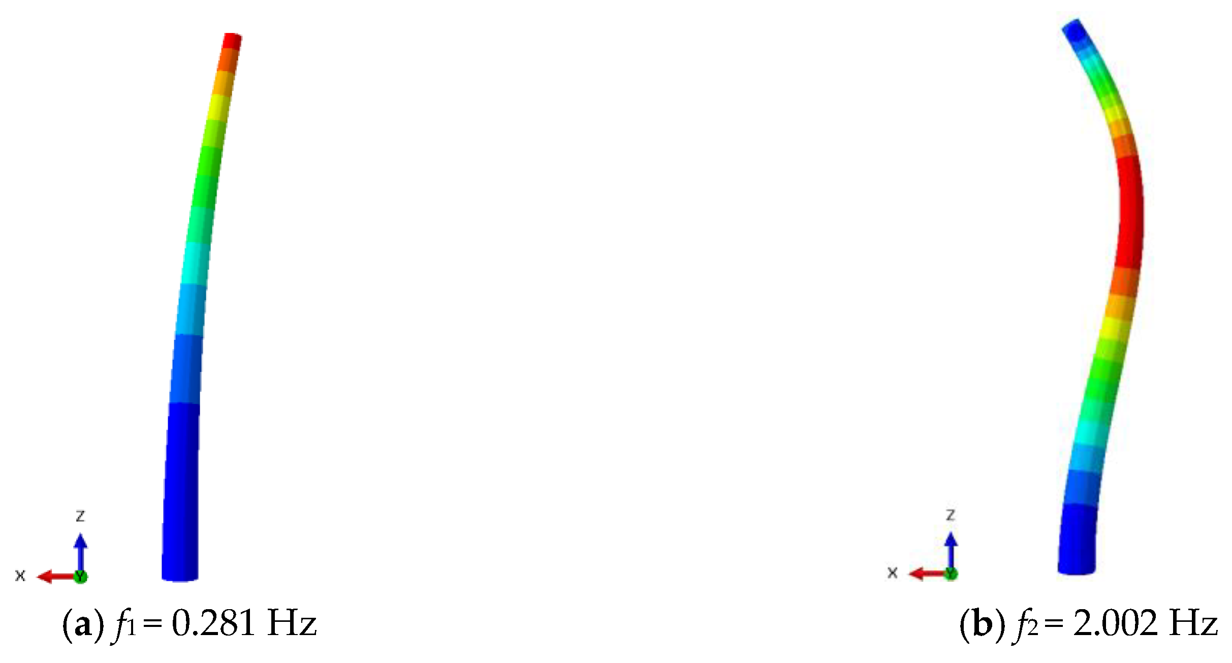
2. Finite Element Modeling and Modal Analysis of the WindPACT-3MW Wind Turbine Tower

The WindPACT-3MW wind turbine tower system has three blades and is controlled by variable speed and pitch. The radius of each blade is 49.5 m, and the weight of each blade is 13.228 tons. The height of the tower is 116.7 m, and the diameters of the bottom and top of the tube tower are 8 m and 3.7 m, respectively. The mass density of the steel used for the tower is 7850 kg/m3, and the elastic modulus is 200 GPa. The rated power of the WindPACT-3MW is 3 MW, and the rated speed is 14.469 rpm. The designed service life of the tower is 20 years. The wind field where the wind power tower is located is the Class I site: the annual average wind speed is 10 m/s, and the maximum wind speed in one year is 52.5 m/s. The main design parameters of the tower system are shown in Table 1.
Based on the above parameters, ABAQUS 2022 software was used to build an FEM for the WindPACT-3MW wind turbine tower. To simplify modeling, the nacelle, hub, and blades on the tower top are simplified as lumped masses that are coupled with the upper edge of the steel tube. During modeling, the C3D8R solid element was used to simulate the steel tube tower, and the mesh size of the model was 0.3 m. The tower bottom was assumed to be fixed without considering the interaction between the soil and structure; that is, the displacement and rotation angle of the tower bottom in the X, Y, and Z directions were constrained. Figure 1 shows the overall FEM and meshing of the conical tower.
The natural frequencies and vibration modes of the first two modes of the structure were calculated using the Block Lanczos method, and the results are shown in Figure 2. As demonstrated in Figure 2, the first two vibration modes of the tower present typical bending shapes, and the corresponding natural frequencies are 0.281 Hz and 2.002 Hz, respectively. Table 2 presents a comparison of the results for the simulated natural frequencies given by the finite element analysis in this study and the actual measurement results of the vibration modes of the tower, as referenced (Rinker J. M. et al.) [18]. As indicated in Table 2, the finite element simulation results in this study are highly in agreement with the values in the reference (Rinker J. M. et al.) [18], and the maximum deviation is less than 1%, which indicates that the established FEM in this study is reliable and can be used to simulate more engineering cases.
The modal analysis results also show that the fundamental frequency of the steel tube tower analyzed in this study is very low, indicating that the overall stiffness of the tower is low, and it is a typical flexible tower. This may entail risks for the operation of the tower under relatively high wind speeds. To increase the stiffness of the tube tower, thereby extending its applicable height for areas with greater wind shear, it is necessary to take some measures to improve the tower. In this study, a part of the tube tower is replaced by a truss to form a hybrid wind turbine tower combining an upper steel tube with a lower steel truss, and its mechanical properties are analyzed in subsequent sections.

3. Analysis of the Static Mechanical Characteristics of a Hybrid Wind Turbine Tower Combining an Upper Steel Tube with a Lower Steel Truss

3.1. Design Parameters and Finite Element Model for the Hybrid Wind Turbine Tower

The hybrid wind turbine tower was designed based on the above parameters of the WindPACT-3MW. The combined tower is composed of an upper conical tube, a connecting piece, and a lower truss. The lengths of the upper tube and the lower truss are both 60 m, and the length of the connecting piece is 3 m. Therefore, the overall height of the combined tower can be preliminarily determined to be 123 m, and the height of the hub is approximately 125 m. The diameters of the top and bottom of the upper tube are 3.9 m and 4.5 m, respectively. The horizontal cross-section of the lower truss is quadrilateral, and the webs are cross-shaped. According to the standard for the design of high-rise structures (GB50135-2019) [19] and a reference (Zhang T.) [20], the width of the truss base was preliminarily selected to be 1/8 of the total height of the tower. The steel used for the upper tube and the lower truss both had a mass density of 7850 kg/m3, an elastic modulus of 200 GPa, and an allowable yield stress of 295 MPa. The wind farm where the tower is located is Class I: the annual average wind speed is 10 m/s, and the maximum wind speed in one year is 52.5 m/s. The detailed design parameters of the combined tower are shown in Table 3.
Similarly, ABAQUS software was adopted to establish the FEM of the combined tower based on the above parameters. To simplify the modeling, the wind turbine rotor, nacelle, and blades at the top of the tower were simplified as lumped masses, which were coupled with the upper edge of the steel tube. The C3D8R solid element was used to simulate the upper tube, with a mesh size of 0.3 m. The main member and web member of the lower truss were simulated using the B31 element with a mesh size of 0.4 m. The upper tube and the lower truss are connected by a transition part. The top of the connecting piece was tied to the tube base. The bottom of the connecting piece and the top of the truss are merged together, and the mesh size is 0.3 m. The interaction between the soil and the structure is not considered, and the tower base is fixed. The final FEM for the hybrid tower is shown in Figure 3.

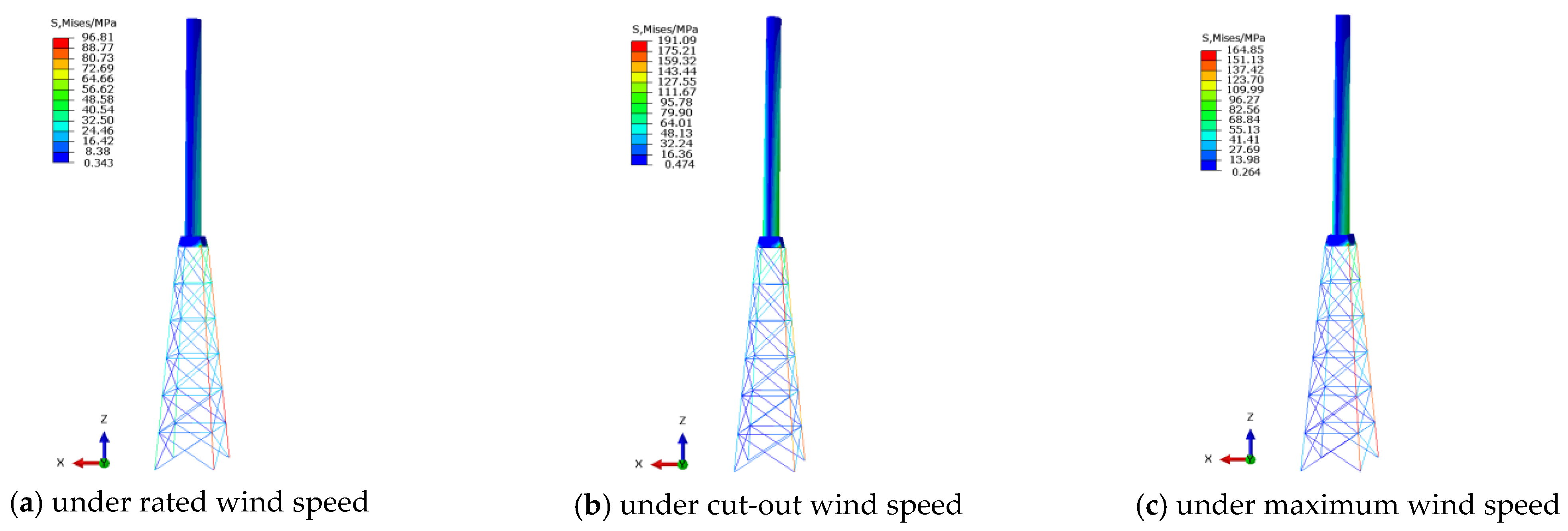
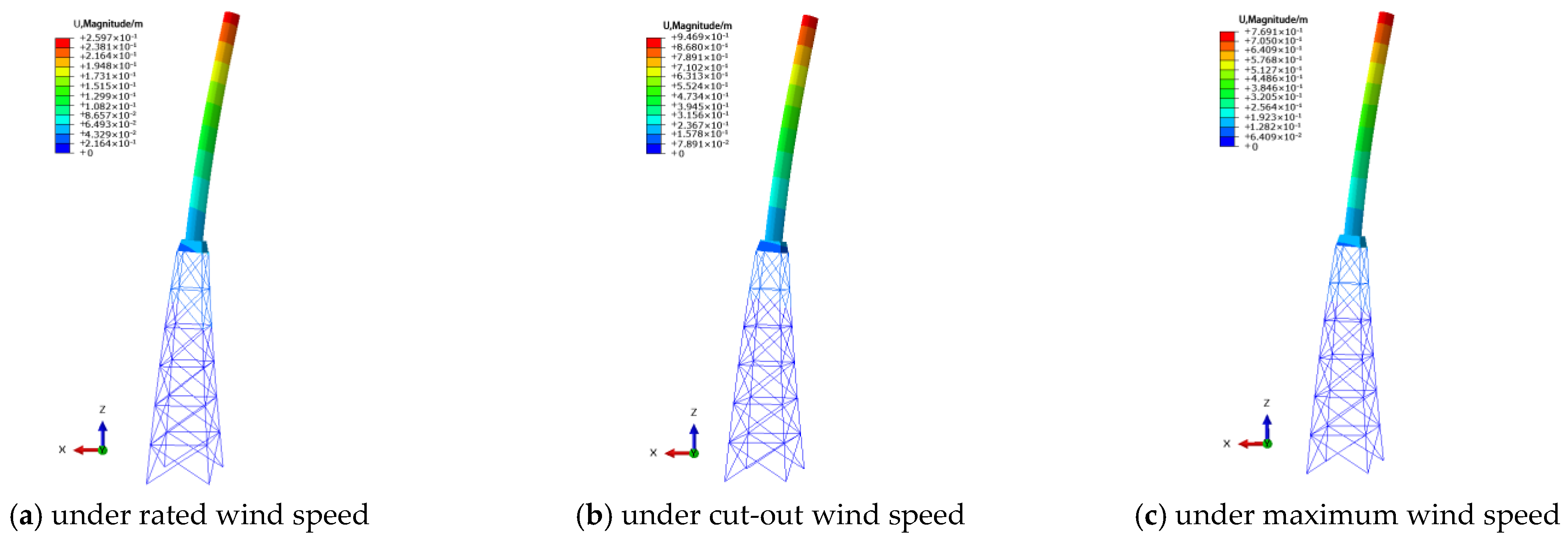
3.2. Analysis of the Static Bearing Capacity of the Hybrid Wind Turbine Tower

The main loads endured by the hybrid tower during operation include the gravity load, eccentric bending moment, hub torque, horizontal thrust of the rotor, and natural wind. A diagram of the structural loads is shown in Figure 4. Since wind loads play the most important role in the operation of a wind turbine tower, three wind speed conditions are considered in the following analysis: the rated wind speed condition (the wind speed is 12.9 m/s), the cut-out wind speed condition (the wind speed is 25 m/s), and the maximum wind speed condition (the wind speed is 52.5 m/s).
The gravity load is mainly generated by the self-weight of the nacelle, hub, blades, and tower, and it can be calculated according to Equation (1):
G = m g
where m is the total mass of the member and g is the gravitational acceleration.
The eccentric bending moment on the tower top can be calculated according to Equation (2):
M = G e
where G is the total weight of the wind turbine acting on the tower top and e is the distance between the center of gravity of the wind turbine and the axis of the tower.
The torque on the hub can be calculated according to Equation (3):
M XH = P n
where P is the output power of the wind turbine and n is the rotation speed of the rotor.
The thrust of the rotor under normal operation can be calculated according to Equation (4):
F = 1 2 C P ρ V 2 A
where CP is the thrust coefficient. For a 3 MW wind turbine, CP = 0.5. ρ is the air density at the location where the wind turbine tower is located. V is the wind speed at the hub height, and A is the swept area of the rotor.
The maximum wind speed occurs when the wind speed reaches 52.5 m/s. At this time, the wind turbine is in the shutdown state [21,22], and the rotor is feathering. For this case, the aerodynamic thrust on the rotor can be calculated according to Equation (5):
F = 1 2 C n ρ V s 2 A b n
where Cn is the thrust coefficient, which is set to 1.6; Vs is the maximum wind speed; Ab is the projected area of the rotor perpendicular to the wind speed; and n is the number of blades.
According to the “Load Code for the Design of Building Structures” (GB50009-2012) [23], the value of the wind load perpendicular to the tower structure can be calculated by Equation (6):
ω k = β z μ s μ z ω 0
where ωk is the characteristic value of the wind load (kN/m2); μs is the shape factor of the wind load; μz is the exposure factor for the wind pressure; βz is the dynamic effect factor of the wind at a height of z; and ω0 is the reference wind pressure (kN/m2).
After calculating the loads based on Equations (1)–(6), a static analysis is performed. The stress and displacement contours of the tower under three wind speed conditions are obtained, as shown in Figure 5 and Figure 6, respectively.
Figure 5 shows that the maximum von Mises stresses of the tower under the three wind speed conditions occur on the main legs of the lower truss, and the stresses on the leeward side are significantly greater than those on the windward side. Under the cut-out wind speed, the maximum von Mises stress in the main leg of the tower reached 191.1 MPa. This value is less than the allowable stress of steel (295 MPa) [24], indicating that the tower can meet the static strength requirement.
Figure 6 shows that under the three wind speed conditions, the maximum displacements occur at the hub height and gradually decrease from the top to the bottom of the tower. Under the cut-out wind speed, the maximum displacement is 0.947 m, which does not exceed one percent of the total height of the tower [19]. In other words, it can meet the allowable lateral deflection requirement of the tower.

4. Static Optimization Analysis of the Hybrid Tower Combining an Upper Steel Tube with a Lower Steel Truss

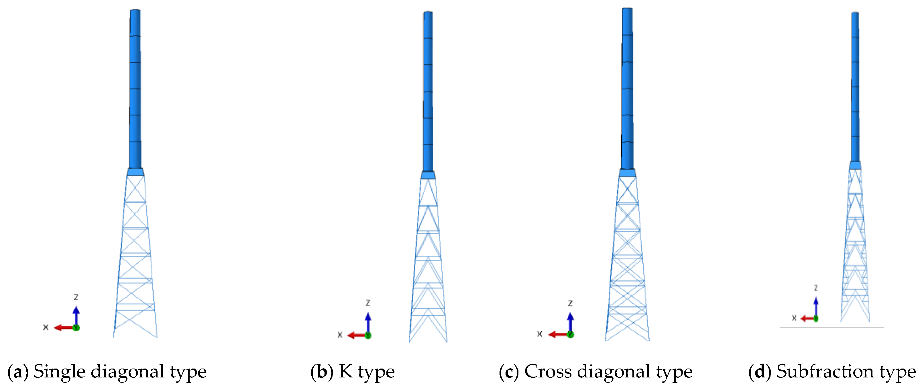
4.1. Influence of the Web Member Type on the Static Bearing Capacity of the Hybrid Tower

The commonly used web member forms for truss towers include the single diagonal type, K type, cross diagonal type, and subfraction type [21]. When keeping the other parameters and analysis conditions the same, the FEMs of the tower with different web member types are shown in Figure 7.
The static bearing capacity of the hybrid tower with different web member forms, as shown in Figure 7, is analyzed under three wind speed conditions. The maximum stress at the truss member and the maximum lateral displacement at the top of the tower are shown in Figure 8.
As shown in Figure 8, the variations in the maximum stress and the maximum displacement of the hybrid tower exhibit similar trends under the rated wind speed, cut-out wind speed, and maximum wind speed conditions. Figure 8 also shows that under the cut-out wind speed condition, the maximum stress and maximum displacement reach the greatest values among the above three wind speed conditions. The maximum stress occurs at the main member of the leeward side of the tower, and the maximum displacement occurs at the top of the tower. In terms of different truss web member types, the maximum stress and displacement of the tower using single diagonal web members, K-type web members, cross diagonal web members, and subfraction web members are 198.4 MPa, 191.1 MPa, 199.3 MPa, 214.4 MPa, 0.959 m, 0.947 m, 0.946 m, and 0.885 m, respectively. According to the current design code, all of the above stresses and displacements meet the strength and deformation requirements. A comparison of the maximum stress and maximum displacement of the tower with different web member types under the cut-out wind speed condition shows that while keeping the other design parameters the same, the stress of the tower using the subfraction-type web member is relatively high, but the deformation is small. This indicates that when designing a hybrid tower combining an upper steel tube with a lower steel truss, it is better to adopt subfraction web members for the lower truss, which can make full use of the steel strength and is economical.

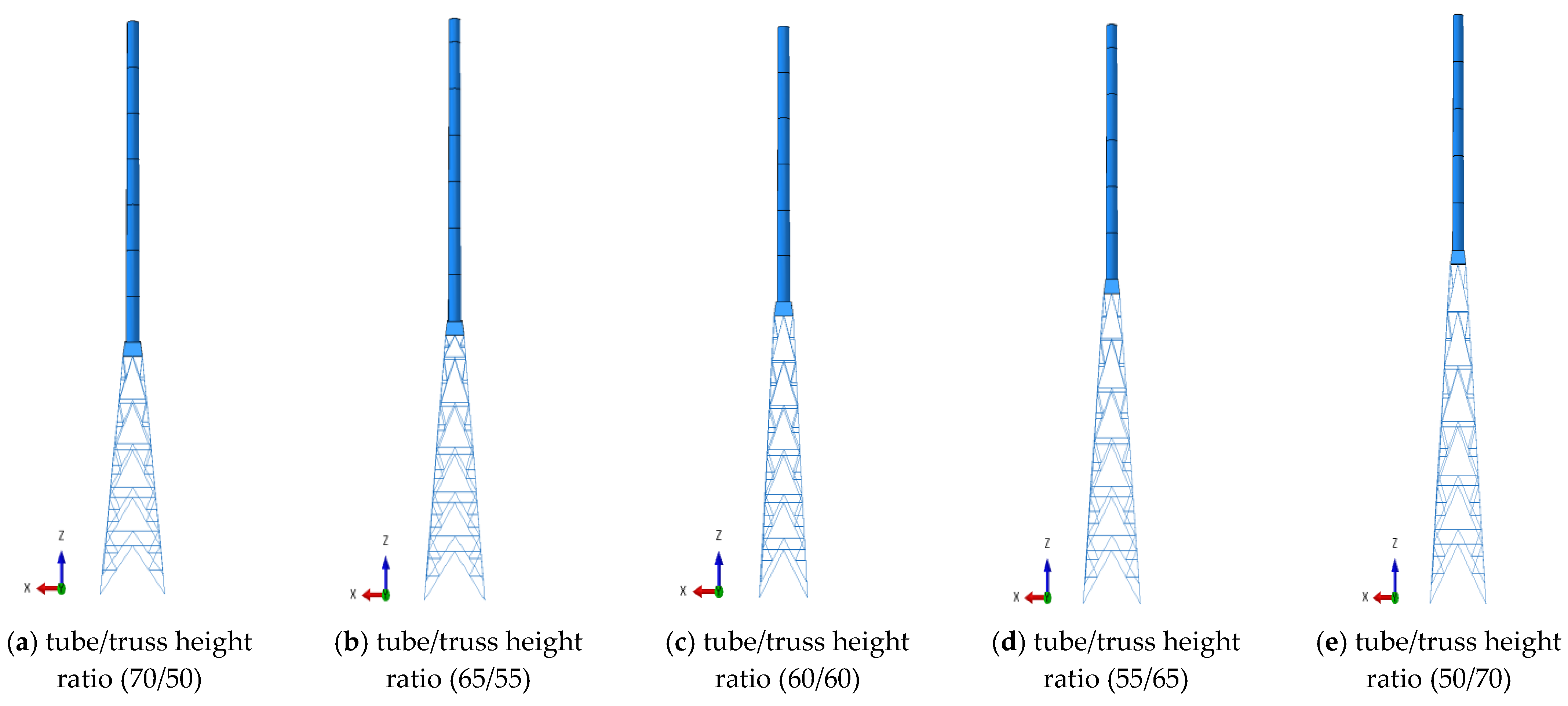
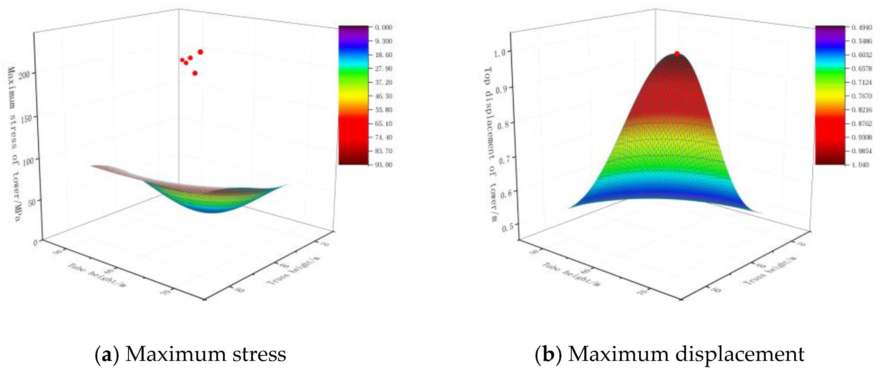
4.2. Influence of the Tube-Height-to-Truss-Height Ratio on the Static Bearing Capacity of the Hybrid Tower

Since the hybrid tower is composed of an upper tube and a lower truss with different stiffnesses, the bending stiffness distribution of the structure is uneven. When the heights of the upper tube and the lower truss are different, the overall bending stiffness of the tower and the lateral displacement will also vary greatly. Therefore, based on the analysis results in the previous section, a hybrid tower using a subfraction web truss is taken as an example to perform the following analysis. The total height of the tower is kept constant (i.e., 120 m), and five towers with different vertical arrangement schemes are selected. The heights of the upper tube and the lower truss are 70 m and 50 m, 65 m and 55 m, 60 m and 60 m, 55 m and 65 m, and 50 m and 70 m, respectively. The FEMs of the hybrid tower with different tube-height-to-truss-height ratios are shown in Figure 9. Taking the cut-out wind speed condition as an example, the maximum stress and maximum displacement of the tower with different tube-height-to-truss-height ratios are shown in Figure 10.
As shown in Figure 10, as the ratio of the tube height to the truss height decreases, the maximum stress and the maximum displacement gradually decrease. This indicates that the lower truss contributes more to the overall bending stiffness of the hybrid tower. In other words, with increasing height of the lower truss, the stiffness of the lower truss increases so that it can embed the upper tube more effectively. At the same time, the overall bending stiffness of the hybrid tower increases with increasing height of the lower truss. Therefore, the structure has a better deformation resistance capacity and can also transfer and disperse loads better, thereby reducing the stress concentration. In practice, it is recommended that the truss height be as large as possible to improve the overall bending stiffness and static load-carrying capacity of the hybrid tower.

4.3. Influence of the Aspect Ratio on the Static Bearing Capacity of the Hybrid Tower

In actual engineering, the span-to-height ratio of a tower may also have a great impact on the global stiffness of the structure. Therefore, the influence of the aspect ratio on the static bearing capacity of the hybrid tower is discussed here. Taking the cut-out wind speed condition as an example, span-to-height ratios of 1/10, 1/9, 1/8, 1/7, 1/6, 1/5, and 1/4 were analyzed, and the results are shown in Figure 11.
Figure 11 shows that as the span-to-height ratio of the tower decreases, the maximum displacement at the tower top gradually decreases. However, the maximum stress of the tower truss member does not change significantly. This indicates that a larger span-to-height ratio can increase the overall stiffness of the tower, resulting in a greater deformation resistance and a smaller maximum displacement at the tower top. However, the maximum stress is mainly affected by the load distribution pattern and structural geometry. Thus, the changing span-to-height ratio of the tower does not directly affect the maximum stress of the tower. In practice, when designing a hybrid tower with the same overall height, appropriately increasing the width of the truss base can effectively increase the bending stiffness of the tower while having little impact on the internal force of the tower.
In summary, when designing a hybrid tower that combines an upper steel tube with a lower steel truss, the most reasonable tower should adopt subfraction web members for the lower truss and use a higher truss and wider truss base if possible. In the subsequent sections, a tower model with the above optimized parameters was used to perform the analysis.

5. Wind-Induced Dynamic Response of the Hybrid Tower Combining an Upper Steel Tube with a Lower Steel Truss

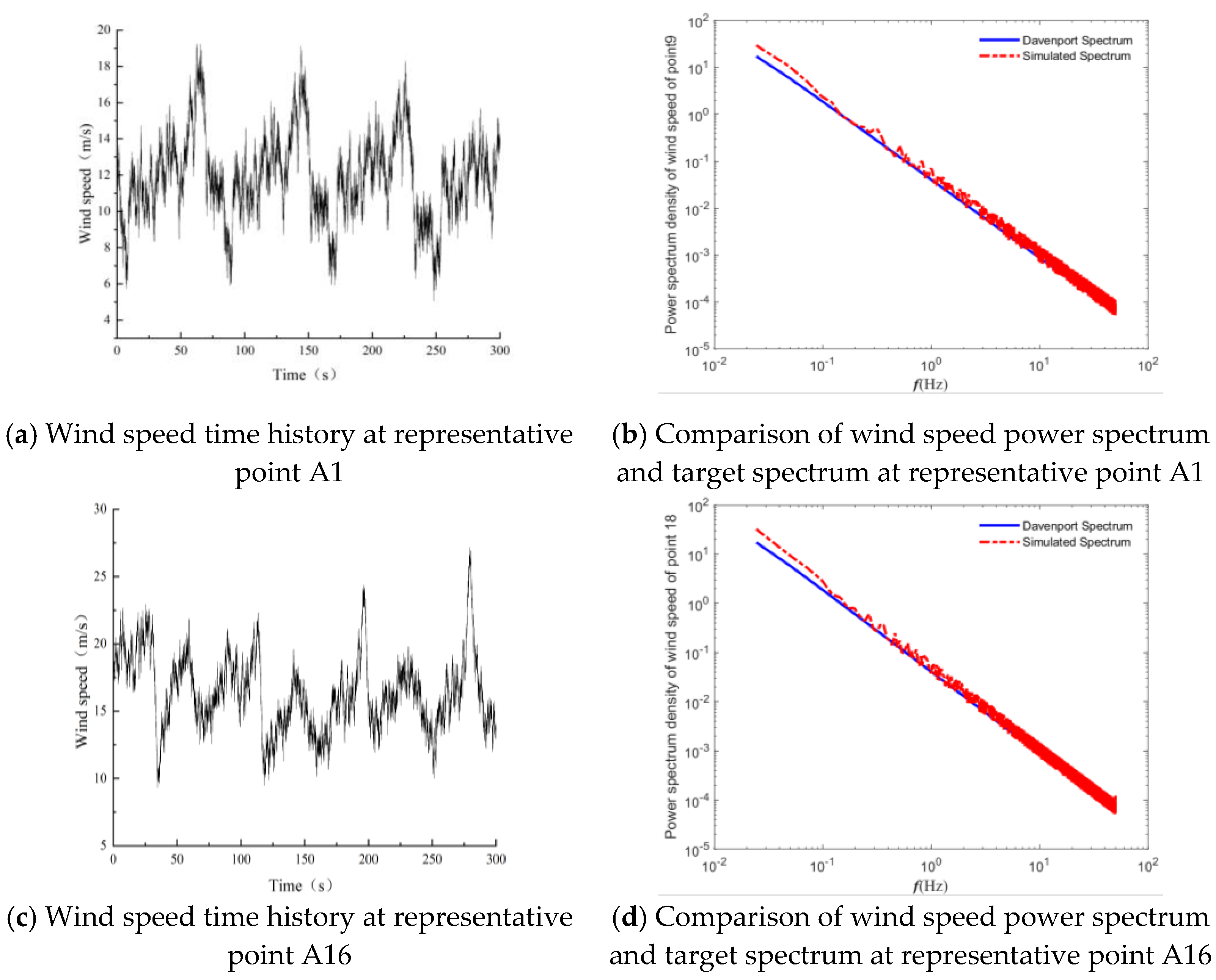
5.1. Wind Load Simulation

In practical engineering applications, a wind turbine tower operates for an extended period of time in an outdoor high-altitude environment, and the structure is often in a complex stress state as a result of the action of various factors. Usually, the dominating load of such high-rise steel structures is the wind load. For a typical wind turbine structure, the wind loads can be decomposed into the natural wind load and the aerodynamic load of the blades.
Many wind measurement data [25] show that natural wind can be divided into a mean wind component and a fluctuating wind component. The variation pattern of the mean wind speed with height can be described by an exponential function, that is,
U ( z ) = U r ( z z r ) α
where U(z) is the average wind speed at a height of z, Ur is the average wind speed at the reference height, zr is the reference height, and α is the ground roughness index.
The fluctuating wind speed can be described using the Davenport spectrum [17], and the expression is as follows:
S v n = 4 k v ¯ 10 2 x 2 n 1 + x 2 4 / 3
where x = 1200 n / v ¯ 10 ; Sv(n) is the power spectral density; k is the coefficient of ground friction; n is the frequency of fluctuating wind; and v ¯ 10 is the mean wind speed after the standard height conversation.
When considering the spatial correlation of wind speed, a coherence function is usually adopted, which can be expressed as
C o h ω = exp 2 n c x 2 x i x j 2 + c y 2 y i y j 2 + c z 2 z i z j 2 v ¯ z i + v ¯ z j
where Cx, Cy, and Cz are the space attenuation coefficients in the x, y, and z directions, respectively, and the values are usually taken as 16, 8, and 10, respectively; v ¯ z i and v ¯ z j are the average wind speeds at the heights of point i and point j, respectively.
The MATLAB program was used to simulate the fluctuating wind speeds of the hybrid tower, considering the spatial coherence of turbulent wind. The time step is set as dt = 0.02, and the total calculation time is set as t = 300 s. According to the characteristics of the hybrid tower, representative points are selected, as shown in Figure 12. Figure 13 presents the simulated wind speed time-history curves and a comparison of the corresponding pulsating wind speed power spectra and the target wind speed spectrum. Due to the large number of wind speed simulation points in this study, only parts of the wind speed time-history curves of the representative nodes of the tower are shown in Figure 13.
As shown in Figure 13, the simulated pulsating wind speed power spectra agree relatively well with the target wind speed spectrum, indicating that the fluctuating wind speed results simulated in this study are highly accurate and can be used for a subsequent wind-induced response analysis of the tower structure.
The aerodynamic load on a wind turbine blade is related to the geometric parameters of the blade, and the blade is usually divided into N microelements along the pitch axis for calculation. Assuming that the microelements do not affect each other, the aerodynamic load on the rotating blade can be calculated based on the blade element momentum theory [26]. For any i-th microelement of a blade, as shown in Figure 14, according to this theory, the relative incoming wind speed Urel can be expressed as the vector sum of the axial wind speed U(1 − a) and the tangential wind speed Ωr(1 + a′), that is,
U rel = U 1 a 2 + Ω r 1 + a 2
where a and a′ represent the axial and tangential velocity induction factors, respectively; Ω is the rotation angular velocity of the blade; and r represents the distance between the microelement segment and the blade root.
The lift force and drag force on the blade element can be expressed as
d F L = 1 2 C l ρ U rel 2 c d r
d F D = 1 2 C d ρ U rel 2 c d r
where dFL is the lift force, dFD is the drag force, Cl is the lift coefficient, Cd is the drag coefficient, and c is the chord length.
According to the geometric relationship, the axial force and tangential force on each blade element can be derived as
d F N = d F L cos φ + d F D sin φ
d F T = d F L sin φ d F D cos φ
where φ is the relative inflow angle, which is related to the wind angle of attack α.
From momentum theory, the axial force and torque acting on the blade element are
d T = 4 π r ρ v 0 2 a ( 1 a ) d r
d M = 4 π r 3 ρ v 0 Ω ( 1 a ) a d r
The axial force and torque acting on the blade element are
d T = 1 2 B ρ c ( r ) v 0 2 C n d r
d M = 1 2 B ρ c ( r ) v 0 2 C t r d r
where ρ is the air density. Cn and Ct represent the lift and drag coefficients, respectively. c(r) is the chord length. B is the number of blades, and dr is the cross-sectional thickness of the blade element.
Three types of fan blade airfoils were selected for this study, among which the lift and drag coefficients of airfoil s825 vary with respect to the angle of attack, as shown in Figure 15.
Integrating the above blade element and momentum theory, the expression of the axial and tangential induction factors can be expressed as
a = 1 4 sin 2 ϕ σ C n + 1
a = 1 4 sin ϕ cos ϕ σ C l 1
Figure 16 and Figure 17 present the time histories of the axial wind load and aerodynamic torque acting on the blades under a wind speed of 12.9 m/s at the hub height.

5.2. Modal Analysis of the Hybrid Tower

Based on the aforementioned optimized hybrid tower model, a modal analysis is performed, and the first three modes of the structure are shown in Figure 18.
As shown in Figure 17, the first two vibration modes of the tower are typical bending modes, the third vibration mode is mainly the local vibration of the upper tube, and the natural vibration frequencies corresponding to the first three modes are 0.467 Hz, 1.27 Hz, and 3.58 Hz. Compared with the results in Table 2, the fundamental frequency of the hybrid tower is greatly improved.
In actual engineering, to avoid resonance between the tower and the rotor, it is necessary to keep the fundamental natural frequency of the tower far from the excitation frequencies caused by the rotor speed (1P) or nP (where n is the number of blades) harmonics from the rotor [12]. Given that the rated speed of the rotor studied in this study is 14.469 rpm, the 1P and 3P frequencies can be calculated to be 0.241 Hz and 0.723 Hz, respectively, which are both far from the fundamental frequency of the tower, indicating that there will be no resonance when blades are running at the rated speed.

5.3. Wind-Induced Vibration of the Tower

The calculated natural wind loads and the aerodynamic loads of the blades are applied to the hybrid tower finite element model, as shown in Figure 4b, and the implicit dynamics module in ABAQUS is adopted to perform a dynamic response analysis of the tower. For a wind turbine tower, complex aerodynamic damping is generated during turbine operation, which mainly affects the dynamic performance of the blades and has little impact on the tower. Therefore, in this study, a constant damping ratio of 0.01 was employed to approximately consider the effects of structural damping and aerodynamic damping on the tower structure during the computation analysis. Figure 19 shows the displacement and acceleration dynamic responses at the hub height of the tower under the rated wind speed.
As shown in Figure 18, under the rated wind speed, the maximum absolute values of the tower displacement and acceleration in the along-wind direction were 0.411 m and 1.38 m/s2, respectively, and the maximum displacement and acceleration in the crosswind direction were 0.027 m and 0.1 m/s2, respectively. The results also show that the along-wind responses of the tower are significantly greater than the crosswind responses, indicating that the aerodynamic thrust generated by the blades is the main factor causing the wind-induced vibration of the tower during normal operation.
Figure 20 shows the stress time history of the most unfavorable locations on the upper tube, the transfer piece, and the lower truss of the tower under the rated wind speed. It is easy to see that the stress level of each part of the tower under the rated wind speed is very low, indicating that the tower can meet the strength requirements during normal operation [24].

6. Fatigue Life Prediction of the Hybrid Wind Turbine Tower Combining an Upper Steel Tube with a Lower Steel Truss

The previous analysis revealed that the displacement and strength requirements of a hybrid wind turbine tower can be met by the current design code under the dynamic action of an instantaneous wind load. However, actual wind turbine towers are often required to have a certain service life. For example, the “Standard for design of steel structures” (GB50017-2017) [24] requires that the design service life of wind turbine towers be no less than 20 years. Under the action of long-term alternating wind loads, members with heavier loads will undergo multiple stress cycles, and the most unfavorable members may be fatigued due to damage accumulation. Therefore, in this section, the wind-induced fatigue life of the hybrid tower is analyzed.
The commonly used Palmgren–Miner theory [27] was adopted to perform the following analysis. This theory considers that the fatigue damage of a material or member has a linear relationship with the number of load cycles. At the same time, fatigue damage can be superimposed linearly. When the cumulative damage reaches a certain value, the material or member will be damaged due to fatigue. In the following analysis, the stress cycle process at the most unfavorable location of the tower was determined. On this basis, the appropriate fatigue–strength curve (S–N curve) was selected to convert the stress performance of the structure to fatigue performance.

6.1. Fatigue Life of the Hybrid Tower at the Rated Wind Speed

The rated wind speed is the wind speed at which the wind turbine tower has the best power generation efficiency during normal operation, and it is also a stable wind speed for the long-term operation of the tower. Therefore, in this section, the fatigue life of the hybrid tower under the rated wind speed is analyzed first. Given that the control system at the top of the tower can ensure that the wind turbine blades always face the wind flow and that the tower mainly bears the aerodynamic load caused by the rotation of the blades, the influence of the wind direction can be ignored when analyzing the fatigue life of the tower. According to Figure 19c, the statistical results of the stress amplitude and number of cycles obtained by the rainflow counting method [28] are shown in Figure 21.
For the hybrid tower, the S–N curve is shown in Figure 22, which is recommended by the “Guidelines and Explanation of the Tower Structure of Wind Power Generation Equipment” [29].
The curve equations can be expressed as follows:
N i = N D ( Δ σ D / Δ σ t . i ) 3 , Δ σ t . i > Δ σ D , if   N i   < 5 × 10 6
N i = N D ( Δ σ D / Δ σ t . i ) 5 , Δ σ t . i Δ σ D , if   5 × 10 6 <   N i   < 1 × 10 9
where ND = 5 × 10⁶ and ΔσD is the fatigue strength when the number of cycles is 5 × 10⁶, which can be obtained from the following formula:
Δ σ D = Δ σ A N A N D 1 3
where NA = 2 × 10⁶ and ΔσA is the fatigue strength when the number of cycles is 2 × 10⁶.
Based on the above stress statistical results and the S–N curve, the annual fatigue cumulative damage coefficient at the most unfavorable locations of the tower under the rated wind speed can be obtained, and the results are shown in Table 4.
As presented in Table 4, under the action of the rated wind speed, the annual fatigue cumulative damage factor of the hybrid tower under different stress amplitudes is 0.021, and the fatigue life of the tower is calculated as 1/0.021 = 47.6 (years), which is much longer than the required design service life.

6.2. Fatigue Life of the Hybrid Tower under Various Wind Speeds Ranging from the Cut-In Wind Speed to the Cut-Out Wind Speed

According to IEC 61400-1 [30], a wind turbine tower will inevitably encounter changes in ambient wind speed during operation, and the fatigue damage of the tower mainly occurs when the wind turbine works properly. Therefore, in this section, the influence of wind loads on the fatigue life of a tower under a wind speed range from the cut-in wind speed to the cut-out wind speed is analyzed. The probability of the annual mean wind speed at the hub height can be estimated by the simplified Weibull distribution [31], which is expressed in Equation (24).
f ( v hub ) = exp π v hub 2 v ave 2
where vhub represents the instant wind speed at the hub height; vave is the annual average wind speed at the hub height, vave = 0.2v; and v is the reference wind speed within 10 min at the site where the wind turbine tower is located.
Given that the wind turbine tower is located at the Class I site, the reference wind speed is 50 m/s, and the annual mean wind speed at the hub height is 10 m/s, the probability distribution of the annual mean wind speed can be calculated according to Equation (24), as shown in Figure 23. The probability of the annual mean wind speed in the range of 3~25 m/s is higher, and the probability in other wind speed ranges is lower.
In the following analysis, the entire range from the cut-in wind speed to the cut-out wind speed is divided into a number of intervals, with a wind speed interval of 2 m/s; then, the annual cumulative hours of each wind speed can be calculated by Equation (25).
T i = 8760 v i Δ v i + Δ f ( v ) d v
Based on Equation (25), the cumulative action times of different wind speeds on the tower can be obtained. Similarly, the annual fatigue cumulative damage coefficient at the most unfavorable locations of the tower under the entire wind speed range from the cut-in wind speed to the cut-out wind speed can be calculated, and the results are shown in Table 5.
Table 5 shows that when the wind load in the entire range from the cut-in wind speed to the cut-out wind speed is considered, the fatigue cumulative damage coefficient of the tower is 0.026, and the corresponding fatigue life is 1/0.026 = 38.5 (years). This value is also much longer than the required service life. Compared to the case of the tower considering only the action of the rated wind speed, the fatigue damage of the tower under the wind load in the entire range from the cut-in wind speed to the cut-out wind speed is more severe, and the fatigue life is reduced by 19.1%. Therefore, the wind loads of a tower should be fully considered when predicting its fatigue life.

7. Conclusions

In this study, a theoretical analysis and numerical simulation methods are used to perform a static optimization analysis, wind-induced vibration analysis, and fatigue life prediction on a hybrid wind turbine tower combining an upper steel tube with a lower steel truss. The main conclusions are as follows:
  • With the same design total height and same material, using a higher truss with subdivided truss webs and larger base dimensions can significantly increase the overall bending stiffness and static bearing capacity of the hybrid wind turbine tower.
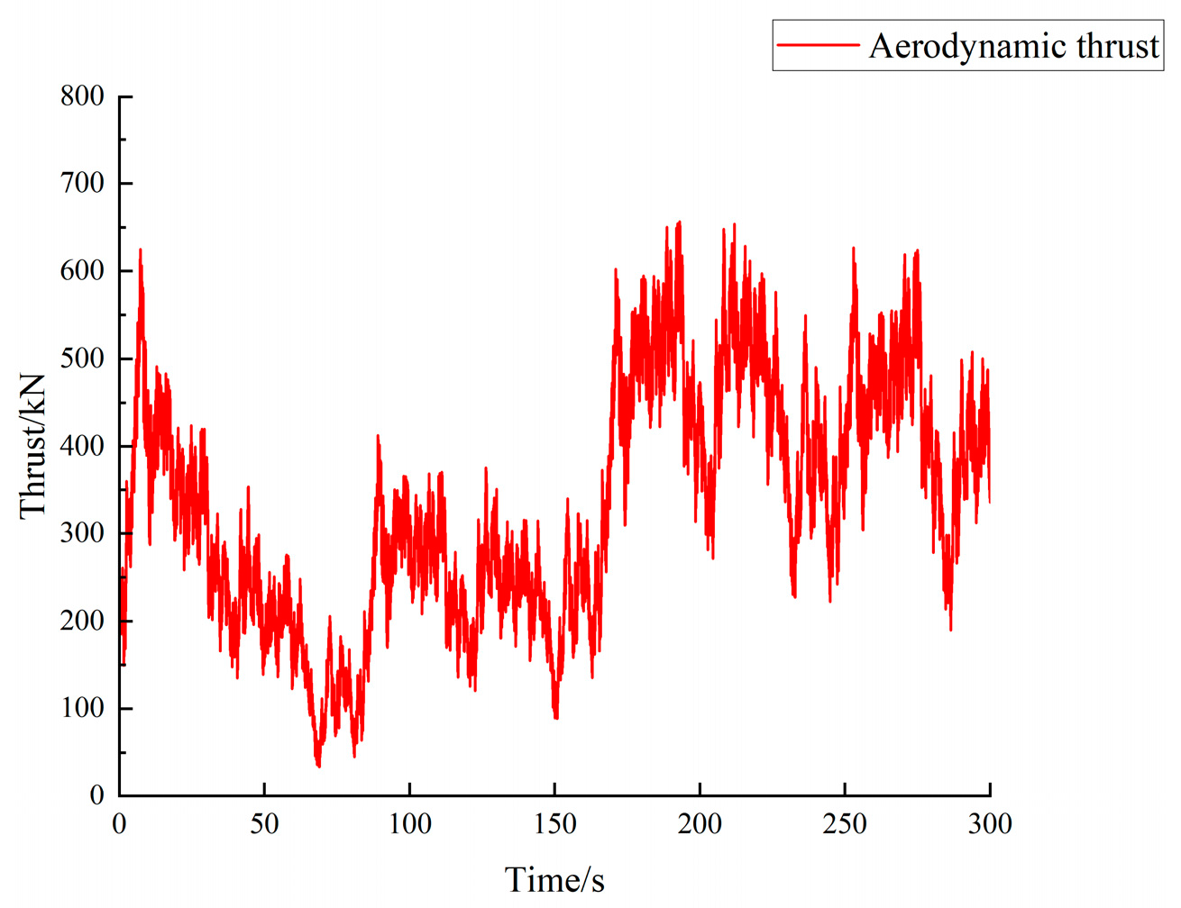
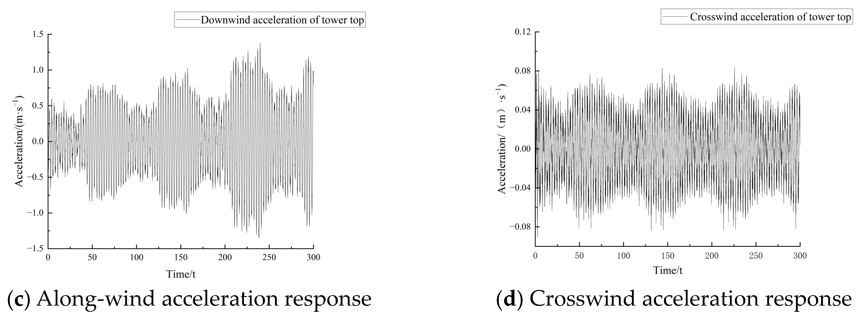
  • The fundamental natural frequency of the hybrid tower is far from the excitation frequencies caused by the rotor speed (1P) or 3P harmonics from the rotor, indicating that there will be no resonance when blades are running at the rated speed. During normal operation, the along-wind responses of the hybrid tower are significantly greater than the crosswind responses, indicating that the aerodynamic thrust generated by the blades is the main factor causing the wind-induced vibration of the tower.
  • For the hybrid tower analyzed in this study, when only the action of the rated wind speed is considered, the annual fatigue cumulative damage factor is 0.021, and the fatigue life is 47.6 (years). When considering the wind load in the entire range from the cut-in wind speed to the cut-out wind speed, the annual fatigue cumulative damage factor is 0.026, and the fatigue life is 38.5 (years). Therefore, when predicting the fatigue life of a hybrid wind turbine tower, the wind loads of the tower should be fully considered.

Author Contributions

Conceptualization, M.Z. and G.Z.; methodology, M.Z., C.X. and T.L.; software, G.Z.; validation, C.X., T.L. and G.Z.; formal analysis, C.X., T.L. and M.N.H.; investigation, T.L. and M.N.H.; resources, M.Z. and G.Z.; data curation, C.X. and T.L.; writing—original draft preparation, M.Z., C.X. and T.L.; writing—review and editing, M.N.H. and G.Z. All authors have read and agreed to the published version of the manuscript.

Funding

This research was funded by the National Natural Science Foundation of China (Grant no. 51578512) and the Natural Science Foundation of Henan (Grant no. 222300420549).

Institutional Review Board Statement

Not applicable.

Informed Consent Statement

Not applicable.

Data Availability Statement

Data are contained within this article.

Conflicts of Interest

The authors declare no conflicts of interest.

References

  1. Global Wind Energy Council. Global Wind Report 2023; GWEC: Brussels, Belgium, 2024. [Google Scholar]
  2. Berny-Brandt, E.A.; Ruiz, S.E. Reliability over time of wind turbines steel towers subjected to fatigue. Wind. Struct. 2016, 23, 75–90. [Google Scholar] [CrossRef]
  3. Jovasevic, S.; Correia, J.; Pavlovic, M.; Dantas, R.; Rebelo, C.; Veljkovic, M.; de Jesus, A.M. Alternative steel lattice structures for wind energy converters Wind energy converters. Int. J. Struct. Integr. 2019, 12, 48–69. [Google Scholar] [CrossRef]
  4. Wu, Y.; Wang, X.; Fan, Y.; Shi, J.; Luo, C.; Wang, X. A Study on the Ultimate Span of a Concrete-Filled Steel Tube Arch Bridge. Buildings 2024, 14, 896. [Google Scholar] [CrossRef]
  5. Wei, J.; Ying, H.; Yang, Y.; Zhang, W.; Yuan, H.; Zhou, J. Seismic performance of concrete-filled steel tubular composite columns with ultra high performance concrete plates. Eng. Struct. 2023, 278, 115500. [Google Scholar] [CrossRef]
  6. Huang, H.; Yao, Y.; Liang, C.; Ye, Y. Experimental study on cyclic performance of steel-hollow core partially encased composite spliced frame beam. Soil Dyn. Earthq. Eng. 2022, 163, 107499. [Google Scholar] [CrossRef]
  7. Wang, Z.; Zhou, T.; Zhang, S.; Sun, C.; Li, J.; Tan, J. Bo-LSTM based cross-sectional profile sequence progressive prediction method for metal tube rotate draw bending. Adv. Eng. Inform. 2023, 58, 102152. [Google Scholar] [CrossRef]
  8. Xiang, Y.; Wang, Z.; Zhang, S.; Jiang, L.; Lin, Y.; Tan, J. Cross-sectional performance prediction of metal tubes bending with tangential variable boosting based on parameters-weight-adaptive CNN. Expert Syst. Appl. 2024, 237, 121465. [Google Scholar] [CrossRef]
  9. Jovašević, S.; Mohammadi, M.R.S.; Rebelo, C.; Pavlović, M.; Veljković, M. New Lattice-Tubular Tower for Onshore WEC—Part 1: Structural Optimization. Procedia Eng. 2017, 199, 3236–3241. [Google Scholar] [CrossRef]
  10. Gkantou, M.; Martinez-Vazquez, P.; Baniotopoulos, C. On the structural response of a tall hybrid onshore wind turbine tower. Procedia Eng. 2017, 199, 3200–3205. [Google Scholar] [CrossRef]
  11. Shah, H.J.; Desai, A.K. Comparison of Monopole and Hybrid Wind Turbine Tower Response for Seismic Loading Under Operational Conditions. J. Vib. Eng. Technol. 2022, 10, 2557–2575. [Google Scholar] [CrossRef]
  12. Gkantou, M.; Rebelo, C.; Baniotopoulos, C. Life Cycle Assessment of Tall Onshore Hybrid Steel Wind Turbine Towers. Energies 2020, 13, 3950. [Google Scholar] [CrossRef]
  13. Farhan, M.; Mohammadi, M.R.S.; Correia, J.A.; Rebelo, C. Transition piece design for an onshore hybrid wind turbine with multiaxial fatigue life estimation. Wind. Eng. 2018, 42, 286–303. [Google Scholar] [CrossRef]
  14. Chen, F.; Zhang, H.; Li, Z.; Luo, Y.; Xiao, X.; Liu, Y. Residual stresses effects on fatigue crack growth behavior of rib-to-deck double-sided welded joints in orthotropic steel decks. Adv. Struct. Eng. 2024, 27, 35–50. [Google Scholar] [CrossRef]
  15. Luo, Y.; Liu, X.; Chen, F.; Zhang, H.; Xiao, X. Numerical Simulation on Crack–Inclusion Interaction for Rib-to-Deck Welded Joints in Orthotropic Steel Deck. Metals 2023, 13, 1402. [Google Scholar] [CrossRef]
  16. Jia, Y.Z.; Yang, W. Statics finite element analysis of combined wind power tower. Hydroelectr. Energy Sci. 2017, 35, 207–211. [Google Scholar]
  17. Tenorio, M.; Cavalcante, M. Optimized Structural Design of Lattice Towers for Wind Turbines. In Proceedings of the XLI Ibero-Latin-American Congress on Computational Methods in Engineering, CILAMCE 2020, Foz do Iguaçu, Brazil, 16–19 November 2020. [Google Scholar]
  18. Rinker, J.M.; Dykes, K. Wind PACT Reference Wind Turbines; National Renewable Energy Laboratory: Golden, CO, USA, 2018.
  19. GB 50135-2019; Standard for Design of High-Rising Structures. China Planning Press: Beijing, China, 2019.
  20. Zhang, T. Research on Structural Dynamic Performance of In-Service Megawatt Wind Turbines; Shenyang University of Technology: Shenyang, China, 2022. [Google Scholar]
  21. Qiu, K.Y.; Ma, R.L.; He, M.J. Research on fatigue resistance of flange joints of 160 m truss-type prestressed steel pipe wind power tower column. Spec. Struct. 2020, 37, 7–12. [Google Scholar]
  22. Luo, Y.X.; Ma, R.L.; Qiu, K.Y. Anti-fatigue design method of frame-type prestressed anti-fatigue steel pipe wind power tower. Dev. Build. Steel Struct. 2021, 23, 73–81. [Google Scholar]
  23. GB 50009-2012; Load Code for Building Structures. China Architecture & Building Press: Beijing, China, 2012.
  24. GB 50017-2017; Standard for Design of Steel Structures. China Building Industry Press: Beijing, China, 2018.
  25. Davenport, A.G. The spectrum of horizontal gustiness near the ground under high winds. Q. J. R. Meteorol. Soc. 1961, 87, 194–211. [Google Scholar] [CrossRef]
  26. Hansen, M.O.L. Aerodynamics of Wind Turbines, 3rd ed.; Routledge: London, UK, 2015. [Google Scholar]
  27. Dowling, N.E. Fatigue at Notches and the Local Strain and Fracture Mechanics Approaches. In Fracture Mechanics: Proceedings of the ASTMSTP, Blacksburg, VA, USA, 12–14 June 1978; ASTM International: West Conshohocken, PA, USA, 1979; pp. 247–273. [Google Scholar]
  28. ASTM. Standard Practices for Cycle Counting in Fatigue Analysis; ASTM: New York, NY, USA, 2017. [Google Scholar]
  29. Zhu, L.; Xu, N.; Gao, Y. Guidelines and Explanation of the Tower Structure of Wind Power Generation Equipment; China Building Industry Press: Beijing, China, 2014. [Google Scholar]
  30. IEC 61400-1:2019; Wind Energy Generation Systems-Part 1: Design Requirements. IEC: Geneva, Switzerland, 2019.
  31. Seguro, J.V.; Lambert, T.W. Modern estimation of the parameters of the Weibull wind speed distribution for wind energy analysis. J. Wind. Eng. Ind. Aerodyn. 2000, 85, 75–84. [Google Scholar] [CrossRef]
Figure 1. FEM and meshing of wind tube tower.
Buildings 14 01441 g001
Figure 2. The first two vibration modes of the steel tube tower.
Buildings 14 01441 g002
Figure 3. The FEM and meshing of the hybrid tower combining an upper steel tube with a lower steel truss.
Buildings 14 01441 g003
Figure 4. A schematic diagram of the loads on the hybrid wind turbine tower.
Buildings 14 01441 g004
Figure 5. Stress contours of the hybrid tower under different wind speeds.
Buildings 14 01441 g005
Figure 6. Displacement contours of the hybrid tower under different wind speeds.
Buildings 14 01441 g006
Figure 7. FEMs of the hybrid tower with different web forms.
Buildings 14 01441 g007
Figure 8. Maximum stress and displacement of the hybrid tower using different truss web types.
Buildings 14 01441 g008
Figure 9. A schematic of the FEMs of the hybrid tower with different tube-height-to-truss-height ratios.
Buildings 14 01441 g009
Figure 10. Maximum stress and displacement of the hybrid tower with different tube-height-to-truss-height ratios.
Buildings 14 01441 g010
Figure 11. Maximum stress and displacement of the hybrid tower with different span-to-height ratios.
Buildings 14 01441 g011
Figure 12. A schematic diagram of the representative points for wind load simulation on the tower.
Buildings 14 01441 g012
Figure 13. Pulsating wind speed time histories at representative points on the tower and the corresponding power spectra.
Buildings 14 01441 g013
Figure 14. A schematic diagram of the forces on a blade element.
Buildings 14 01441 g014
Figure 15. Lift and drag coefficients of airfoil s825.
Buildings 14 01441 g015
Figure 16. Aerodynamic load on the blade.
Buildings 14 01441 g016
Figure 17. Aerodynamic torque on the blade.
Buildings 14 01441 g017
Figure 18. The first three vibration modes of the hybrid tower.
Buildings 14 01441 g018
Figure 19. Time history of the displacement and acceleration responses at the hub height of the tower under the rated wind speed.
Buildings 14 01441 g019aBuildings 14 01441 g019b
Figure 20. Stress–time-history curves at the most unfavorable locations of the tower under the rated wind speed.
Buildings 14 01441 g020
Figure 21. A statistical histogram of the stress amplitude and number of cycles at the most unfavorable locations of the tower under the rated wind speed.
Buildings 14 01441 g021
Figure 22. S–N curve for wind turbine tower.
Buildings 14 01441 g022
Figure 23. The probability of the annual average wind speed at the Class I wind site.
Buildings 14 01441 g023
Table 1. Design parameters of the WindPACT-3MW wind turbine tower.
ItemsValueItemsValue
Rated power3 MWMass of tower351,798 kg
Rotor diameter99 mNacelle mass132,598 kg
Number of blades3Rotor mass101,384 kg
Hub height119 mHub diameter4.95 m
Swept area7693.8 m2Steel mass density7850 kg/m3
Cut-in wind speed3 m/sSteel elastic modulus200 GPa
Rated speed14.469 rpmSteel shear modulus76.0 GPa
Rated wind speed12.9 m/sCut-out wind speed25 m/s
Table 2. Comparison of the simulated natural frequencies and the results given in the literature (Rinker J. M. et al.) [18].
Mode OrderSimulated Frequency in the Present Study (Hz) f0Frequency Results Given by Reference (Rinker J. M. et al.) [18] (Hz) fRelative Deviation (%)
|(f0f)/f0|
10.2810.2830.7
22.0021.9960.3
Table 3. Design parameters of the hybrid wind turbine tower.
ItemsValueItemsValue
Rated power3 MWLength of the upper tube60 m
Diameter of the tube top3.9 mDiameter of the tube bottom4.5 m
Wall thickness at the top of the tube48 mmWall thickness at the bottom of the tube64 mm
Truss height60 mWidth of the truss top6.5 m
Width of the truss base15 mMain material specification of the truss680 × 14 mm
Diagonal member specifications of the truss272 × 6 mmWeb member specification of the truss272 × 6 mm
Steel mass density7850 kg/m3Steel elastic modulus200 GPa
Table 4. Annual fatigue damage coefficients corresponding to each stress range under the rated wind speed.
Stress Range (MPa)Actual Annual Number of Stress CyclesTheoretical Annual Number of Stress CyclesAnnual Fatigue Damage Coefficient
4.91331.07 × 10123.24 × 10−8
13.66326.4 × 1095.42 × 10−4
24.88333.19 × 1091.09 × 10−3
34.37386.35 × 1086.29 × 10−3
42.12212.3 × 1089.6 × 10−3
50.72129.07 × 1081.39 × 10−3
67.7484.75 × 1071.78 × 10−3
Annual fatigue cumulative damage coefficient: 0.021
Table 5. Annual fatigue damage coefficients corresponding to each stress range under the entire wind speed range from the cut-in wind speed to the cut-out wind speed.
Wind Speed (m/s)Annual Lasting Hours (h)Equivalent Stress Range (MPa)Actual Annual Number of Stress CyclesTheoretical Annual Number of Stress CyclesAnnual Fatigue Damage Coefficient
3529.31.0231.3 × 1062.72 × 10154.78 × 10−10
5963.95.0412.0 × 1069.36 × 10122.14 × 10−7
71236.67.5113.44 × 1061.27 × 10122.71 × 10−6
91324.931.472.99 × 1066.68 × 1094.48 × 10−4
111250.155.252.63 × 1062.97 × 1098.86 × 10−4
131063.760.52.68 × 1069.57 × 1082.8 × 10−3
15826.671.172.25 × 1062.57 × 1088.75 × 10−3
17591.296.411.54 × 1061.41 × 1091.09 × 10−3
19390.9139.211.07 × 1064.48 × 1082.39 × 10−3
21239.9153.396.62 × 1051.61 × 1084.11 × 10−3
23136.9187.473.78 × 1051.39 × 1082.72 × 10−3
2572.8208.882 × 1047.23 × 1062.77 × 10−3
Annual fatigue cumulative damage coefficient: 0.026
Disclaimer/Publisher’s Note: The statements, opinions and data contained in all publications are solely those of the individual author(s) and contributor(s) and not of MDPI and/or the editor(s). MDPI and/or the editor(s) disclaim responsibility for any injury to people or property resulting from any ideas, methods, instructions or products referred to in the content.

