Review

Progress in Theoretical Modelling of Macroscopic and Microscopic Dynamics of Bolted Joints in Complex Equipment

1
College of Nuclear Science and Technology, Naval University of Engineering, Wuhan 430030, China
2
College of Power Engineering, Naval University of Engineering, Wuhan 430030, China
*
Authors to whom correspondence should be addressed.
Lubricants 2024, 12(5), 182; https://doi.org/10.3390/lubricants12050182
Submission received: 15 April 2024 / Revised: 9 May 2024 / Accepted: 14 May 2024 / Published: 17 May 2024

Abstract

:
Bolt connection structure is a common form of connecting large and complex equipment. Its object contact surfaces under normal and tangential loads will appear in the form of slip and adhesion, which affects the service life of mechanical equipment. Bolted connection structures cause changes in stiffness and damping, which have great impacts on the dynamic characteristics. Experimental studies and numerical simulations have difficulty predicting the overall performance of bolts in a timely manner, hence cannot ensure the reliability and safety of complex equipment. In order to improve the overall performance of complex equipment, it is necessary to study the contact theory model of bolt connection structures. Based on the relationship between friction force and velocity in the classical friction model, the mathematical expressions of restoring force and tangential displacement in the kinetic theory model are deduced to predict the stiffness degradation of the bolted structure and to characterise the kinetic properties and laws of the bolted structure. From the perspective of theoretical calculation, it makes up for the situation in which it is difficult to measure the performance of bolts due to the existence of spanning scale and provides theoretical support for the reliability of connecting complex equipment. This paper summarises and analyses the contact theory model of bolt connection structures, ranging from macroscopic to microscopic; describes the static friction model, kinetic friction model, statistical summation contact model, fractal contact model; and analyses the influencing factors of the microscopic contact mechanism. The advantages and disadvantages of the kinetic theoretical models are described, the manifestation of friction and the relationship between tangential force–displacement are discussed, and the key research directions of the kinetic theoretical models of bolted structures in the future are elucidated.

1. Introduction

High-strength bolted structures have an important role in the operation of important mechanical equipment such as aerospace and complex equipment [1]. While most of the parts of mechanical products, such as bolted joint structures, are scrapped due to excessive wear and tear, mechanical products will be greatly enhanced if mechanical friction and wear can be controlled and reduced [2,3]. Bolted joint structures are the weak link in the safety and reliability of complex equipment. Under external loads, the connection interface in the normal and tangential directions will produce nonlinear behaviours such as contact, separation, slip, adhesion, etc., leading to preload relaxation and the nonlinear degradation of connection stiffness. This poses a great challenge to the assessment of equipment dynamic performance degradation, reliability assessment prediction, and structural design. The bolt connection structure is located in the inner side of the bonding surface. There is a nonlinear cross-scale phenomenon, which makes it difficult to predict the overall performance of the bolts in a timely manner through experimental research and numerical simulation, and it is not possible to ensure the reliability and safety of complex equipment.
How to accurately represent the contact slip mechanism of rough surfaces, how to establish the corresponding nonlinear models under different mechanical behaviours at the connection interface, and how to calculate the complex nonlinear mechanical problems at the interface of the connection structure are the key problems in the study of bolted structures. Therefore, it is necessary to establish a set of nonlinear stiffness degradation models from basic scientific support to practical engineering applications to solve the above problems. Based on the kinetic model for studying the relationship between tangential force, plate displacement, and friction force, the theoretical equation can solve the structural stiffness degradation, along with energy dissipation equations, and the bolt can be judged to be in sticking, micro-slip, macro-slip, and separate states, as shown in Figure 1. The kinetic model can make up for the shortcomings of experimental research that cannot be monitored in real time, which helps to predict the working state and performance of the bolt, and can improve the safety and reliability monitoring of large and complex equipment. In response to the above problems, researchers and scholars have established many contact models to describe the friction at the interface of complex structures. Based on the relationship between friction and velocity, the relationship between external load recovery force and displacement is gradually deduced, and the theoretical model that can predict the performance of the bolt is finally constructed. The study of kinetic theory model starts from the Coulomb model to introduce the definition of friction, and then research scholars sought to establish the kinetic theory model to calculate the friction research.
Friction theory is the premise for the study of theoretical models of friction dynamics, and scholars have long studied the phenomenon of friction. However, the progress of tribological research has been slow for a long time. It was not until the 16th century that Da Vinci, an Italian scholar, began a systematic study of tribology [4]. He put forward two laws of friction: friction force and normal force is proportional to the relationship; and friction force is independent of the contact area of the object and the opposite direction of motion [5]. The term “tribology” was introduced in the “Jost Report” [6]. In 1699, Amontons [7] proposed two classical laws of friction: the friction force is proportional to the normal load applied to an object; and the friction force is independent of the contact area between objects. In 1781, Coulomb summarized the previous research and proposed two other laws of friction based on experimental findings: the coefficient of friction is independent of the sliding speed of the object; and the coefficient of static friction is greater than the coefficient of sliding friction. Subsequently, Coulomb proposed the theory of mechanical friction [4], which is the “surface concavity hypothesis”. When two contact surfaces are embedded in each other, a static friction force is generated, and this force prevents the relative movement of the contact surfaces. The two contact surfaces can move relative to each other only after the bumps on the contact surfaces are flattened, deformed, or crushed. According to the theory, the smoother and flatter the contact surfaces are, the lower the friction is. However, this theory cannot explain the phenomenon that friction increases significantly when the contact surface is very smooth and has major drawbacks. Desaguliers proposed the molecular adhesion theory, which discarded the surface bump hypothesis. He stated that friction is generated by molecular interaction between the jointing surfaces of the contacting objects [8] and proposed the hypothesis that the smoother the friction surface, the greater the friction force. In 1929, Tomlinson [9] hypothesized that when two molecules come into contact, i.e., enter each other’s repulsive field, and separate, energy loss occurs, which manifests itself as friction. This theory did not make any assumptions about the causes of gravitational and repulsive forces and viewed molecules as simple centres of force fields. The final distribution of the lost energy among the various possible degrees of freedom is also not considered in the theory, which deals only with the molecular mechanism of the conversion of work into heat. And later, Kraguelsky [10] in 1939 found that friction has to overcome not only the intermolecular forces but also the effect of the microscopic contact surface roughness. In 1945, Bowden and Tabor found [11] that under the action of a normal force, the real surface area of the two objects in contact is actually smaller than the nominal contact surface area. Microscopically, the surface of the object is not smooth; there are bumps and undercuts, and when the normal force increases, the object is pressed down and contacts with more bumps, and its true contact area increases. It is also proposed that its bump contact area is squeezed to produce adhesion and cold weld junctions, and its friction is the sum of the force that shears the cold weld junctions and the force required to contact the surface furrows of the object. In 1971, Israelachvili developed an instrument that can directly measure the molecular forces on solid surfaces, the surface force meter [12]. The Tribology Laboratory of Tsinghua University [13] conducted an in-depth study of the surface force instrument in 1999, comparing the theoretical models of adhesion and non-adhesion, and experimentally found that the Hertz theory matches the experimental results of non-adhesive contact, while the JKR theory can better describe the phenomenon of adhesion. After the continuous improvement of the apparatus, it can be applied to subject areas such as fine-scale fluid dynamics and nanotribology [14,15,16,17,18].
Since Bowden and Tabor proposed the theory of adhesive friction, research scholars have failed to make significant breakthroughs in macroscopic friction [19]. Research scholars have studied more on the kinetic theoretical models of connection structures, especially the Iwan model in dynamic friction model and the GW model and MB model in the microscopic friction model for rough surfaces, as well as the kinetic theoretical models through the finite element method. By recovering the force–object displacement curve, the bolt connection is characterised to be in viscous, micro-slip, and macro-slip states, and the degradation of structural stiffness and energy dissipation phenomena of the bolt connection of complex equipment are predicted. The construction of the kinetic theory model helps to improve the service performance monitoring of the mechanical system, the system life cycle, and the overall performance of the bolted joint structure. In order to have a more comprehensive understanding of the current state of research on theoretical models of connection structure dynamics, this paper focuses on the research progress of macroscopic friction models of connection interfaces [20,21,22] and microscopic friction models of rough surfaces [23,24] in a review and analysis. The advantages and disadvantages of the various models are compared, and the directions for future research are described.

2. Macroscopic Friction Models for Connected Interfaces

Based on the contact surface of the bolt connection with the flat plate, the expressions of bolt tangential restoring force and displacement are constructed to describe the bolt fastening state stage, as shown in Figure 2. The macroscopic friction model is divided into the static friction model and dynamic friction model. The existing static friction model is mainly used in the calculation of simulation software, which can accurately judge the state of the connection structure and solve the friction force. The dynamic friction model can be used in the theoretical analysis of engineering practice, which can characterise the energy dissipation, stiffness degradation, and contact mechanism between objects, especially for the Valanis model and Iwan model. By constructing the hysteresis return line using the theoretical friction model, the energy dissipation between objects and the change in bolt contact state can be accurately described. From the aspect of theoretical calculation, it makes up for the situation that it is difficult to measure the bolt performance due to the existence of cross-scale and provides theoretical support for the connection reliability of complex equipment.

2.1. Static Friction Model

Early researchers and scholars have conducted a lot of studies on static friction, and their models are mainly divided into the Coulomb model, Coulomb viscous model, static friction Coulomb viscous friction model, and Stribeck model.

2.1.1. Coulomb Model

The Coulomb model was the first model to introduce a definition of friction, where friction is independent of velocity and only related to the normal force. However, the Coulomb model is only an idealised model and does not describe the magnitude of friction in an object with a non-zero velocity, and the Coulomb model is often used as a friction compensation.
f y = f c sgn ( υ )
where f y is the friction force of the object, f c = μ | N | is the Coulomb friction force, μ is the coefficient of friction, N is the normal force, and υ is the sliding velocity.

2.1.2. Coulomb Viscosity Model

In the 19th century, fluid mechanics continued to develop, and research scholars found that viscosity exists in some fluids, which led to the proposal of the Coulomb + viscosity model, which is known as the Coulomb viscosity model. The viscous friction force arises from the viscous behaviour of the fluid lubrication layer between the contact surfaces, which is proportional to the velocity and also has a value of 0 when the velocity is [25].
The linear viscous friction model is
f y = f υ υ
where f υ is the viscous friction coefficient. In order to better fit the model to the experimental data, researchers have established a model that has a nonlinear linear relationship with the absolute value of velocity [26], which is as follows:
f y = f υ | υ | δ υ sgn ( υ )
where the value of δ υ lies in the shape of the surface of the contacting object.
Therefore, the Coulomb viscous model can be expressed as the Coulomb + linear viscous model:
f y = f υ υ + f c sgn ( υ )

2.1.3. Static Friction Coulomb Viscous Friction Model

The static friction model describes the magnitude of the friction force in the absence of relative motion between objects, albeit in the presence of a relative tendency [25]. This friction force is related to the magnitude of the external force and is independent of the relative velocity. In general, when the external force on an object is less than the maximum static friction, the static friction force is in the opposite direction to the external force and is equal in size. When the external force is greater than or equal to the static friction, the magnitude of the static friction is equal to the maximum static friction for
f y = { f e if   v = 0   and   | f e | < f s f s sgn ( v ) if   v = 0   and   | f e | f s
where f e is the external force and f s is the maximum static friction.
Morin [27,28] introduced a static friction model into the Coulomb viscous friction model as follows:
f y = { f e if   v = 0   and   | f e | < f s f s sgn ( v ) if   v = 0   and   | f e | f s f v v + f c sgn ( v ) o t h e r w i s e

2.1.4. Stribeck Model

In 1902, Stribeck found through experimental studies that the change in friction force is different from the linear trend of Coulomb’s viscous friction model. The friction force exceeds the maximum static friction when the relative velocity of the object is low, and the friction force decreases as the velocity increases. In 1982, Bo and Pavelescu [29] proposed an exponential model to describe Stribeck’s research findings as follows:
f y = f c + ( f s f c ) e [ ( υ υ s ) δ ]
where υ is the Stribeck velocity and υ s and δ are empirical constants.
Armstrong [25] refined this model by adding viscous friction as follows:
f y = f c + ( f s f c ) e [ ( υ υ s ) δ ] + f υ υ
Stribeck model for Equations (7) and (8) are combined as follows:
f y = { f e if   v = 0   and   | f e | < f s f s sgn ( v ) if   v = 0   and   | f e | f s f c + ( f s f c ) e [ ( v v s ) δ ] + f v v o t h e r w i s e
where f e is the external force, f s is the maximum static friction, f c is the Coulomb friction, υ is the sliding velocity, and υ s is a set empirical constant.

2.1.5. Other Models

The Karnopp model [30] was developed to compensate for the above friction models that require equation transformations to determine the relative sliding velocities. This model defines an interval D V υ D V ; when the velocity is in this interval, the default velocity is 0 and the magnitude of the friction force is determined by the external force; when outside of this interval, the friction is a function of the velocity. The value of DV is determined by the different operating conditions. Although this method avoids the problem of how to determine that the velocity is 0 [31]; however, the method for determining the value of DV is not clear. The authors of [32] identified the parameters of this model and calculated the value of DV using a graphical method. However, this method is affected by noise and has serious limitations.
Armstrong proposed a seven-parameter ( f c ,   f y ,   F s , ,   k t ,   υ s ,   τ L ,   γ ) friction model [33], which can better determine and calculate the sticking phase, sliding phase, and variable static friction phase. The model can accurately determine the friction state, however, due to the seven positional parameters, parameter identification is difficult, and a complete parameter identification system has not been developed, and there are huge limitations in the practical application of this method.
In recent years, researchers and scholars have gradually established the contact model through finite element software and applied the static friction model formula to the finite element algorithm, and better results were achieved by constructing the model through ANSYS 2022, ABAQUS 2022, and MATLAB 2023 software.
In 2009, Buczkowski [34] constructed an elastic-plastic micro-contact model by using the finite element method based on the various isotropy as well as orthogonal anisotropy of the contact interface, considering the rough surface modelling as a stochastic process. In 2012, Yang [35] digitally simulated microscopic rough surfaces, constructed a 3D point cloud model of mutually contacting rough surfaces in ANSYS, and analysed the contact characteristics such as normal force and true contact area. In 2018, Wu [36] constructed three-bit microscopic rough surfaces by ANSYS and MATLAB software, performed parametric finite element modelling using APDL, and carried out further analysis of contact and stress conditions. In 2020, Wei [37] constructed a two-dimensional rough surface profile in MATLAB based on the WM function and completed finite element modelling using the secondary development of ABAQUS. By calculating the relationship between the friction coefficient and the load, the error between the experimental results and the theoretical results is not more than 10%, which proves the correctness of the present method. In 2021, Weimin Wu [38] constructed a turning micro-roughness 3D morphology model based on ABAQUS and compared it with the KE model to verify the correctness of the method.
The high-precision finite element model of bolts and plates can be established to identify parameters of the macro friction model of the interface. The slip force and specific parameters of the bolted interface were identified by the finite element results, and the errors between them and the theoretical model were analysed. The hysteresis loop, energy dissipation per unit period, and backbone curve were obtained. Finite element can capture the nonlinear characteristics of the connected structure, make up for the defects of experimental research, and verify the accuracy of the prediction of the theoretical model. The finite element model is shown in Figure 3.
The above studies show that the friction model constructed by the finite element method is mature, and the experimental results are not much different from the theoretical results. However, the finite element model still has the problems of precise meshing and model convergence, and there is no good solution at present. The static friction model has fewer parameters and a simple form, which cannot accurately describe the dynamic friction behaviour or characterize the friction hysteresis. Therefore, researchers are committed to studying dynamic friction models that can accurately describe the motion behaviour of objects.

2.2. Dynamic Friction Models

Dynamic friction model includes Dahl model, sideburns model, LuGre model, Valanis model, Iwan model, etc., of which the research scholars have studied the Iwan model more. The dynamic friction model can make up for the shortcomings of the static friction model, but there are some problems of its own.

2.2.1. Dahl Model

Dahl [39] proposed a method to deal with Coulomb friction damping oscillators, applied to the ordinary friction model and carried out with rolling bearing servo system dynamic friction experiments [40]. The results of this study show that before the objects about to move relative to each other did not reach the maximum static friction, there was no relative displacement but a small micro-slip. The Dahl model is a continuous model, which solves the problem of discontinuity in the static friction model as well as friction hysteresis. Its differential equation is
d f y d x = σ 0 ( 1 f y f c sgn ( υ ) ) α
where A is the stiffness factor, B is the displacement, and C is the fitting factor, which is used to fit the shape of the curve in Figure 4.
This model is described from the time domain perspective as follows:
d f y d t = d f y d x d x d t = d f y d x υ = σ 0 ( 1 f y f c sgn ( υ ) ) α υ

2.2.2. Sideburns Model

In order to study the motion state of the convex peaks on the contact surface of microscopic angle objects. Haessing and Friedland established a microscopic sideburns model [41,42], as shown in Figure 5. The microscopic object motion process is assumed to be elastic sideburns and rigid sideburns; above the moving elastic sideburns, below the stationary rigid sideburns, and when the two move against each other, the contact interface will produce friction. The expression is
f y = b = 1 b k 0 ( X E , b X R , b )
where k 0 is the number of elastic sideburns above, X E , b , X R , b are the positions of elastic and rigid sideburns, respectively, and N is the total number of sideburns.
The higher the number of sideburns, the more complex the model is and also affects the computational efficiency. The literature shows that when the number of sideburns is 20–25, it is more effective in calculating friction [43]. Because it is difficult to construct a large number of sideburns with small space in the simulation calculation, this model is less often used in simulation calculation.

2.2.3. LuGre Model

The Dahl model cannot describe the static friction and Stribeck effect, and the sideburns model cannot calculate the friction in the case of random sideburns. Therefore, based on the above problems, Canudas proposed the LuGre model [44,45], which treats the kinematic state of the sideburns of the microscopic rough contact surface as an average deformation, and its modelling function is
d z d t = υ z | υ | g ( υ ) σ 0
where z is the average sideburn deformation, σ 0 is the sideburn stiffness, and g ( υ ) is the Stribeck effect.
The expression for friction is given by:
f y = σ 0 z + σ 1 d z d t + σ 2 υ
where σ 1 is the microscopic damping coefficient (generally a constant [46]), and σ 2 is the viscous friction coefficient.

2.2.4. Leuven Model

The LuGre model is a more perfect model. However, it still has the disadvantages of not considering local memory and not being able to adapt to arbitrary force–displacement curves. Therefore, Swevers constructed the Leuven model [47,48] based on the above problems, which can accurately model the two states of sliding and pre-sliding without a transition function. And it was applied to the friction behaviour of the robot to achieve accurate tracking.
f y = F h ( z ) + σ 1 d z d t + σ 2 υ
F h ( z ) = F d ( z ) + F b
d z d t = υ [ 1 sgn ( F d ( z ) S ( υ ) F b ) | F d ( z ) S ( υ ) F b | n ]
where F h ( z ) is the static nonlinear force containing nonlocal memory, F d ( z ) is the excess curve, F b is the starting position, S ( υ ) is the friction behaviour, and n is the friction coefficient.
Leuven model is considered as the complete model to confirm the behaviour of the system through various parameters to get accurate tracking. However, this model has six parameters with three mechanisms, which makes parameter identification more difficult and the model more complex.

2.2.5. Valanis Model

The Valanis model is often used as a nonlinear theoretical model in the modelling of bolted structures [49] and plastic structures [50]. The model can generalize the microscopic and macro-slip motion between the contact interfaces of the connected structure and the response of the structure under dynamic loading with the functional expression [51]:
T ( x ) = E 0 x [ 1 + sgn ( x ) λ E 0 ( E t x F ) ] 1 + κ sgn ( x ) λ E 0 ( E t x F )
λ = E 0 α 0 ( 1 κ E t E 0 )
where T ( x ) and x are the restoring force and displacement, E 0 ,   E t are the parameters of the material, κ is the dimensionless parameter, and α 0 is the yield point parameter. Setting different parameters according to the requirements, the nonlinear behaviour of the structure subjected to external forces can be observed, and in the parameter processing and optimization through MATLAB, the accurate identification value under the excitation state can be obtained [52], and the working principle of its Valanis model is shown in Figure 6.

2.2.6. Iwan Model

Based on the bilinear hysteresis model (the system is defined as a series–parallel combination of two linear springs and a damper) and assuming that the hysteresis system consists of elastic–plastic units with different yield limits [53], Iwan [54,55,56] constructed the structurally simple Iwan hysteresis model and obtained the steady-state response equations, of which their theoretical modelling data and experimental data are shown in Figure 7. The Iwan model consists of n ideal-case elastic–plastic Jenkins cells, while a single sliding damper and a linear spring of stiffness k t n form an elastic–plastic Jenkins cell with a maximum yield force f i * n .
ϕ i is the yield displacement, and the relationship between yield displacement and yield force in the whole system is
f i * = k t × ϕ i
During the initial loading stage, the sliding damper is subjected to a tangential tension T, which produces a displacement x. When the tangential displacement x is less than the yield displacement ϕ i , the yield force of a single Jenkins cell is
f i ( x ) = k t n × x
When the tangential displacement x is greater than the yield displacement ϕ i , the yield force of a single Jenkins cell is
f i ( x ) = f i * n
When the loading direction of the force–displacement curve changes, the yield force can be expressed as
f i ( x ) = [ k t x ( k t A f i * ) ] N , A 2 ϕ i x A
f i ( x ) = f i * n , x A 2 ϕ i
where the maximum displacement in the A backbone curve, as shown in Figure 8.
During the initial loading stage, the total tangential force of the system consists of two components, the force generated by the yielded member and the force generated by the un-yielded member:
T ( x ) = i = 1 b f i * n + k t x n b n
where b Jenkins cells yielded and n-b cells have not yielded; T is the tangential force.
When the number of Jenkins cells is approximately infinite, the relationship between the tangential force and displacement at the initial loading stage (backbone curve) is
T ( x ) = 0 k t x f * φ ( f * ) d f * + k t x k t x φ ( f * ) d f *
where φ ( f * ) represents the density function of the yield force. The density function of the yield force in the classical Iwan model is uniformly distributed, as shown in Figure 9. When x , the tangential force is expressed as follows:
T ( x ) = 0 f * φ ( f * ) d f *
Similarly, the relationship between tangential force and displacement in the unloading stage is
T ( x ) = 0 k t ( A x ) 2 f * φ f * ( f * ) d f * + k t ( A x ) 2 k t A [ k t x ( k t A f i * ) ] φ ( f * ) d f * + k t x k t A φ ( f * ) d f *
Based on the Msaing’s criterion, the expressions for the restoring forces and displacements for the cycles of the loading and unloading phases can be deduced as follows:
T ( x ) = T ( A ) + 2 T ( A + x 2 )
T ( x ) = T ( A ) 2 T ( A x 2 )
When macroscopic slip occurs, the tangential force versus displacement is given by Equation (27) with a stiffness of 0. While there is still residual stiffness present in the system, Song [57] added a separate linear spring with a stiffness of that shown in Figure 10 to the Iwan model. Its tangential force versus displacement is given by
T ( x ) = 0 x ϕ ρ ( ϕ ) d ϕ + x x ρ ( ϕ ) d ϕ + k x
where k is the residual stiffness of the independent linear spring, and ρ ( ϕ ) = k t 2 φ ( f * ) is the density function of the yield displacement:
ρ ( ϕ ) = R [ H ( ϕ ϕ 1 ) H ( ϕ ϕ 2 ) ] + k δ ( ϕ ϕ )
where H ( ϕ ) and δ ( ϕ ) are the Heaviside function and Dirac function, respectively; R is a parameter; ϕ 1 is the yield displacement at the onset of micro-slip; ϕ 2 is the yield displacement at the onset of macro-slip; and ϕ is much higher than the yield displacement at ϕ 1 and ϕ 2 .
The application of the Iwan model is limited to the case where the normal load is constant, and Rajaei proposed a generalized Iwan model with variable normal load in order to study the effect of the normal load on the contact [58] and validated it for beams with frictional contact support. Segalman studied the relationship between energy dissipation and loading and proposed a four-parameter Iwan model containing the force F s , stiffness K T , and dimensionless parameter χ ,   β required for macroscopic slip [59]. This model can predict the force–displacement curve at any moment, but it is difficult for this model to output the residual stiffness. Li proposed a six-parameter model based on the double impulse function and the truncated power–law distribution function [60], with the parameters of the onset positions of micro-slip and macro-slip ϕ 1 ,   ϕ 2 , the change in contact stiffness when macro-slip occurs, as well as the residual contact stiffness K 2 ,   K and the power–law distribution R ,   α . Improved methods of the parameter identification and discretization of the model are used to derive force–displacement expressions. The six-parameter model provides better characterization than the four-parameter model.
The contact area of a bolted joint structure varies under tangential load application, but all existing Iwan models assume a constant contact area [61]. In view of this, Wang classified the Iwan models into two categories: dynamic Iwan models for which the contact area and pressure remain variable [62,63], and static Iwan models for which the contact area and pressure are assumed to remain constant [64]. In the study of the dynamic Iwan model based on the case of applied mixed loads, the expressions for the contact boundary function and the dynamic pressure function were proposed, and by using the constraint method of modification, a density function solution method was obtained that can characterize both of them. In the static-Iwan model based on Fernlund’s compression function, hysteresis return lines and backbone curves are derived, and the correctness of the model is proved by experiments and finite element methods.
In recent years, researchers have studied the Iwan model further, and Liu Bing proposed the parametric modelling of Iwan model using classical Ansys [65]. Zhu modelled and identified the parameters of bolted structures based on the six-parameter Iwan [66]. Iwan has good applicability and can better characterize the dynamics of bolted structures, but some of the parameters do not have a clear meaning, and some of the assumptions are oversimplified, ignoring the physical properties.
Six commonly used dynamic friction models were introduced above, and there are many other models, such as the generalized friction model [67,68], the time-lag model [69,70], the Maxwell model [71], the Bilman–Sorine model [72], the Bouc–Wen model [73,74], and the shear layer model [75,76,77], etc. The static friction model is simple, and it cannot characterize the dynamics of bolted structures. The static friction model is simple and cannot reflect the real characteristics of the object according to the actual situation, the dynamic friction model solves this problem and can better characterize the physical properties; however, there are more model parameters, and the construction of a simple and effective parameter identification method has become an urgent problem to be solved at present.

3. Microscopic Friction Model for Rough Surfaces

The kinetic friction model presented above is mainly from the macroscopic point of view of the object. However, the object indicates that it is not smooth, there are a large number of bumps and a certain degree of roughness, the surface of the object is in contact through the bumps, and the contact area is not a measured surface area but a real contact area [11], as shown in Figure 11 and Figure 12. Researchers and scholars have then proceeded to conduct research from the microscopic point of view, trying to establish a link between the contact model of the bolted joint structure and the microscopic mechanism.
Bolted structures interact with flat metal plates, and the microscopic contact surfaces are coupled when the object is subjected to normal compressive loading [78]. It tends to cause changes in the actual contact area and local stress concentrations. This leads to an increase in the tangential tension required to move the object, which causes material failure and reduced friction. This effect can strongly affect the friction characteristics by more than 10 per cent. The contact surface coupling effect also alters the displacement, which, in turn, leads to the separation of the contact surfaces and the appearance of gaps. This may even cause the leakage of confined fluids, seriously affecting the safety performance of the structure. Meng [79,80] investigated the effects of the thickness of flat plate structures and the contact surface coupling effects on the properties of flat plates. The shear force at the interface in the substrate with thinner material thickness strongly affects the friction and contact area. Mixed load coupling produces asymmetric contact for the elastic and viscoelastic dimensions, which affects the change in contact area [81,82], which in turn generates additional friction. Therefore, in order to study the real contact area and surface morphology of microscopic rough surfaces, a large number of researchers and scholars have constructed a variety of microscopic friction models. The friction models can be divided into statistical summation contact model and fractal contact model.

3.1. Statistical Summation Contact Model

The statistical summation contact model with other statistical methods, assuming that there are a variety of micro-convex body on the surface of the object, including the measurement, calculation, and other methods, can determine the height of the micro-convex body on the surface of the object, height difference, equivalent radius R, and other parameters, in conjunction with the material parameters of the object, such as Young’s modulus, density, and so on. The density function of the micro-convex body on the surface of the roughness can be determined. By solving the density function under certain constraints, the height profile of the micro-convex body can be calculated Z ( x ) . Based on the statistical summation method, the deformation and force analysis of all the micro-convex bodies are carried out to obtain the friction force.

3.1.1. GW Model

In 1966, Greenwood proposed a new model, the Greenwood–Williamson (GW) model [83]. The following basic assumptions were made: the rough surface is isotropic; the bumps are spherical near their vertices and have a radius of curvature; only the bumps deform when the objects are in contact; the surfaces of the contacting objects are assumed to be in contact between a rough surface and an ideally smooth surface, whereas the number and shapes of the microbumps on the rough surface are random, and there are no interactions between the bumps. Through the Hertzian theory of a single micro-convex body, the real contact area is calculated by using the method of statistical summation, which is
A = π N β d ( z d ) ϕ ( z ) d z
where N is the number of bumps, z is the height of the bumps on the rough surface, β is the radius of the hypothetical bump, ϕ ( z ) is the probability that the height of a particular rough body on the reference plane is between z and z + dz, and d is the distance between the ideal plane of the rough contact surface and the smooth plane.
The GW model is suitable for smaller normal loads, and when the load is larger, the micro-convex body deforms more, without focusing on the principle of volume conservation, so the calculation error is larger.

3.1.2. CEB Model

The GW model is to describe the pure elastic model, which cannot describe the elastic–plastic roughness model. Therefore, Chang proposed the Chang–Etsion–Bogy (CEB) model [84]. An approximate model is used to predict the contact area of the rough body without considering the exact shape, and the model controls the volume conservation of the micro-convex body during plastic deformation. The contact area equation for a single micro-convex body is expressed as
A ¯ = π R ω ( 2 ω c ω )
where A ¯ is the real contact area of a slightly convex body, ω c A is the deformation height of a single micro-convex body at the beginning of plastic deformation, ω is the deformation height of a single micro-convex body during the stress process, and R is the radius of curvature.
The CEB model agrees with the GW model in predicting the true contact area in general. However, the GW model cannot be applied to critical cases such as contact surface separation, and the CEB model is limited in its narrow range of applicability and does not explore the stage between purely plastic and fully elastic deformation [85].

3.1.3. KE Model

In 2002, Kougut and Etsion optimised the CEB model based on the establishment of an elastic–plastic finite element model of a deformable sphere in frictionless contact with a smooth plane [85,86]. By applying normal contact loads, the variation rules of the three stages of fully elastic, elasto-plastic transition, and fully plastic contact interface were investigated. The whole elastic–plastic phase was also divided into two stages based on the factorless parameter ω / ω c . By identifying the normal load P c and contact area A c ¯ when plastic deformation is generated by finite elements, the normal load P and contact area A ¯ of the two stages are expressed. The classical Hertzian contact is extended to the fully plastic contact, and the Kougut–Etsion (KE) model applicable to any elastic or plastic deformation is established.
( P P c ) 1 = 1.03 ( ω ω c ) 1.425 a n d   ( A ¯ A c ¯ ) 1 = 0.93 ( ω ω c ) 1.136   for   1 ω ω c 6
( P P c ) 2 = 1.40 ( ω ω c ) 1.263 a n d   ( A ¯ A c ¯ ) 2 = 0.94 ( ω ω c ) 1.146   for   6 ω ω c 110
where ω c A is the deformation height of a single micro-convex body at the beginning of plastic deformation, and ω is the deformation height of a single micro-convex body during the stress process.
Based on the above normal contact model study, Kougut found that the static friction coefficient is significantly affected by the normal contact load and the adhesive force. In order to derive the expression of the static friction coefficient, it is based on the assumption that the individual variable spheres are independent of each other. The dimensionless normal contact load P in the normal KE model is calculated by statistical summation. The dimensionless static friction force Q max and dimensionless adhesion force F s are calculated by using the Gaussian distribution probability density function, and the relationship between the three is shown in Figure 13. This method proves that the classical friction law is only applicable to certain cases, the static friction force applicable to the elastic–plastic contact, adhesion, and sliding stages is constructed, and the results are more accurate.
Therefore, the coefficient of friction, the factorless static friction, can be expressed as follows [87]:
μ = Q max F = Q max P F s
Q max = 2 3 π β K a ω c * [ 0.52 d * d * + ω c * I b 1 + d * + ω c * d * + 6 ω c * ( 0.01 I b 2 + 0.09 I b 3 0.4 I b 4 + 0.85 I b 5 ) ]
where β is the roughness parameter, K a is the hardness coefficient, and ω c * is the critical point of fully elastic deformation, I b * = ( z d ω c ) b * ϕ ( z ) d z .

3.1.4. BKE Model

The above model has been investigated mainly for the normal load and actual contact area. Only the expression for the tangential static friction was calculated, and the effect of the tangential load on the model was not considered. Therefore, Brizmer [88,89] investigated the contact behaviour of a variable sphere with an ideal rigid plane under mixed loads in 2007. The coefficient of static friction was found to decrease with increasing normal load, and eventually stabilised at around 0.3 for small normal loads. The resulting Brizmer–Kligerman–Etsion (BKE) model better describes the contact behaviour of a variable sphere with an ideal rigid plane under mixed normal and tangential loads. The theoretical results do not differ much from the finite element results, which proves the correctness of the model, shown in Figure 14.
In addition to the above commonly used models, statistical summation contact models include Cohen et al.’s combination of the BKE model with the GW model and the proposed Cohen–Kligerman–Etsion (CKE) model [90,91]. Greenwood and Tripp proposed the Greenwood–Tripp (GT) model based on the elastic deformation theory and the GW model [92,93]. Whitehouse proposed the microscopic rough contact surface with Archard proposed the Whitehouse–Archard (WA) model with three assumptions and two statistical parameters [94]. Jackson proposed the Jackson–Green (JG) model based on the material parameters, hardness, and dimensions of the micro-convex body [95]. Nayak proposed the Nayak model based on the geometric theory of statistics [96,97]. Zhao proposed the Zhao–Maietta–Chang (ZMC) model based on the 4th order polynomials and the three stages of deformation of the micro-convex body [98], etc. The microscopic friction model of rough surfaces using statistical summation can better describe the external appearance of rough surfaces and better explain the physical mechanism, but the rough surfaces of objects are random, and their models cannot accurately describe the real contact characteristics, only assuming that the contact surfaces are in first contact. The accuracy of the model is also limited by the precision of the measuring instrument.

3.2. Fractal Contact Modeling

In 1967, Mandelbrot proposed fractal geometry based on the principle of coastline length variation [99]. Majumdar constructed the Majumdar–Bhushan (MB) model in 1991 based on the Weierstrass–Mandelbrot (W-M) model [100] by applying the ideas of fractal theory to the microscopic friction model of rough surfaces [101]. The conception that the rough surface of an object consists of a continuum of micro-convex bodies that can be infinitely enlarged, that the rough surface is not smooth, and that the micro-convex bodies can be infinitely subdivided is proposed. The W-M model function can represent the rough surface contour in two-dimensional coordinates, and its expression is
z ( x ) = G D 1 n = n 1 cos 2 π γ n x γ ( 2 D ) n ; 1 < D < 2 ; γ > 1
where z ( x ) is the contour height, D is the fractal dimension, and G is the characteristic coefficient.
Based on the W-M model in the fractal geometry of shoreline change, the true contact area between objects is derived as follows:
A = D 2 D A 1 ¯ = 0 A 1 ¯ n ( A ¯ ) A ¯ d A ¯
where A ¯ is the contact area of a single microbump, n ( A ¯ ) is the distribution function, and A 1 ¯ is the maximum contact area of a single microbump.
In 1994, Wang [102] investigated the frictional warming phenomenon on microscopic rough surfaces, and based on the statistical temperature rise distribution of a single microbump and the maximum temperature rise of a fractal, he determined the density distribution function of the temperature rise in the real contact area and proposed a modified MB model with a total real contact area as follows:
A ¯ = D 2 ( 2 D ) ψ ( 2 D ) 2 a L
where ψ is the domain expansion factor of the micro-contact size distribution, and a L is the maximum truncated area.
In 2022, Cao [103] derived the distribution function of the truncated area of the micro-convex body based on the fractal theory and MB model and proposed a friction coefficient model based on the normal force, fractal dimension, and characteristic coefficients, and verified the correctness of the model through experiments. When the maximum truncation area is smaller than the critical truncation area, pure plastic deformation occurs, and its actual contact area is as follows:
S = ( D 1 3 D ) s m
When the maximum truncation area is larger than the critical truncation area, the mixing deformation occurs, and its actual contact area is as follows:
S = D 1 6 2 D [ 1 + ( s c s m ) ( 3 D ) / 2 ] s m
where s is the truncated area of the micro-convex body, and s m is the maximum truncated area of the micro-convex body.
The core idea of MB model is to construct the probability density function and then calculate the real contact area by integration. In recent years, the MB model has been used in the fields of friction coefficient measurement, material wear, sealing, etc. [104,105,106]. The MB model can well characterize the real contact area and the relationship between the contact area and the load based on the fractal dimension D and the characteristic coefficient G, and the model is not affected by the sampling length and the accuracy of the instrument. However, it does not consider the elastic-plastic deformation state and the microscopic rough contact surface of the object may not be suitable for the fractal theory, so there are some limitations.

3.3. Study of Microscopic Contact Mechanism

All of the above microscopic contact mechanics models use spherical and circular shapes to approximate the roughness of the microscopic surfaces, with the micro-convex bodies acting independently on the contact surfaces and no interaction between multiple micro-convex bodies. The measured true contact area is smaller than the calibrated contact area. In the elastic range, when a single micro-convex body is deformed by extrusion, its elastic deformation will extend for a certain distance in the tangential direction, affecting the deformation of other micro-convex bodies. Only when the normal force is small, the above model can achieve more accurate results. Persson improved the above problem [107,108] and proposed a new contact theory from the perspective of arbitrary size of normal force. The stress probability distribution function P ( σ , ζ ) of the contact surface is constructed through the amplification of an arbitrary reference length ζ . The Persson contact theory employs numerical simulation to investigate the effects of different parameters on the contact surface. A calculation equation is derived to satisfy the surface with arbitrary roughness. The Persson contact theory can calculate the actual contact area of the rough surface of microscopic contact in elastic and elastoplastic phases, and its theoretical prediction results are more accurate. This study is the most effective contact theory among the current microscopic contact theories.
P ( σ , ζ ) = δ [ σ σ 1 ( x ) ]
where σ 1 ( x ) is the stress generated in the contact zone after the surface roughness is smoothed, σ is the stress throughout the contact area, and δ is a set coefficient.
Since statistical summation contact models and fractal contact models are mostly studied for two-dimensional planes, they do not satisfy the three-dimensional contact of bolted joints. Therefore, Persson proposed a method to calculate the coefficient of kinetic friction of microscopic three-dimensional contact surfaces [109] and investigated the effect of adhesive force on the coefficient of friction. A contact theory in which the degree of surface contact varies with magnification was proposed.
Rough surfaces of metallic materials undergo plastic deformation at first contact, causing changes in surface roughness and microscopic local stress concentrations. Tiwari [110] carried out numerical simulations on the rough surfaces based on the boundary element method. It was found that the metal undergoes elastic deformation when the surface stress is less than the indentation hardness. When the local stress reaches the indentation hardness, the metal deforms plastically. In this case, the indentation hardness depends on the length scale of the selected micro-interface.

4. Conclusions and Future Directions

By establishing a kinetic theory model to describe the phenomenon from “appearance” to “mechanism”, constructing force–displacement expressions, microscopic surface contact morphology, and other forms. The bolt connection in viscous, micro-slip and macro-slip states were characterised, and the stiffness degradation and energy dissipation of the bolt connection in large and complex equipment were predicted. This model can circumvent the problems of inability to monitor in real time and nonlinear cross-scale in engineering and improve the overall safety performance of complex equipment. This paper provides an overview of the research progress of the macroscopic friction model of connection interfaces and the microscopic friction model of rough surfaces. The static friction model has fewer parameters and a simple form, which cannot accurately describe the dynamic friction behaviour or characterize the ability of friction hysteresis. However, it can be applied to finite element analysis, and the finite element contact model has been widely used in a variety of research fields. Its mesh division is more difficult, the problem of model non-convergence is difficult to be solved, and the generality is poor. The dynamic friction model solves this problem. It can better characterise the physical properties. However, it has more model parameters, and the construction of a simple and effective parameter identification method has become an urgent problem. The statistical summation contact model can better describe the appearance of rough surface and better explain the physical mechanism. However, the rough surface of an object has randomness, and its model cannot accurately describe the real contact characteristics, only assuming that the contact surface is the first contact. The accuracy of the model is also limited by the precision of the measuring instruments. The fractal contact model is not affected by the accuracy of the instrument and can characterise the stiffness and damping variations, but its universality is low and fractal parameters need to be obtained. The Persson contact theory analyses the mechanism of microscopic contact surfaces and investigates a variety of parameters affecting the real contact area with a high degree of accuracy.
In recent years, certain progress has been made in the dynamic modelling, but there are still some problems, and future research should be carried out in the following aspects:
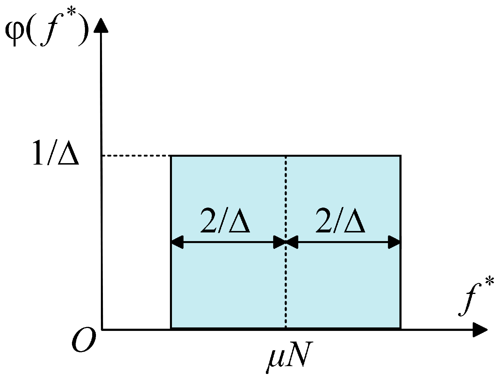
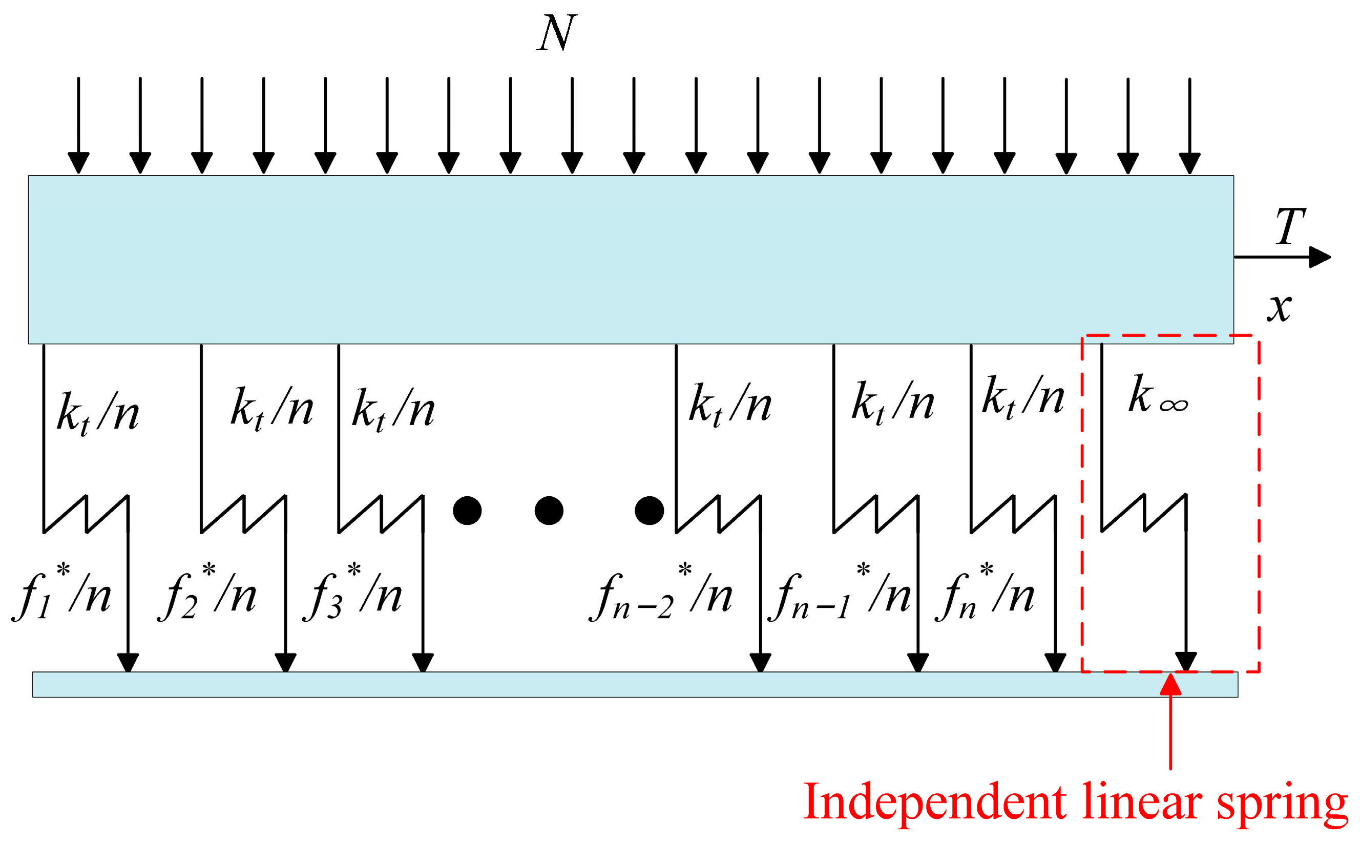
  • The Iwan model is still the focus of research, especially regarding the yield force density function from the bolt contact mechanism, the addition of a normal load, based on the change in contact area and dynamic pressure for the dynamic Iwan model. Their models can better characterise the evolution of the contact state, reflecting the dynamic degradation characteristics, residual stiffness. However, the contact area function and dynamic pressure change function still need to be corrected at special points.
  • A complete set of parameter identification methods should be established. Even if the dynamic model of bolted structures can accurately characterise the dynamic properties, the difficulty in parameter identification will lead to difficulties in model application.
  • The problems of the cross-scale and non-linearity of bolted structures should be solved. Simple dynamic models of bolted structures can no longer meet the current needs, and the problems of cross-scale and non-linearity seriously affect the life of bolts. At present, it is necessary to carry out research on this aspect.
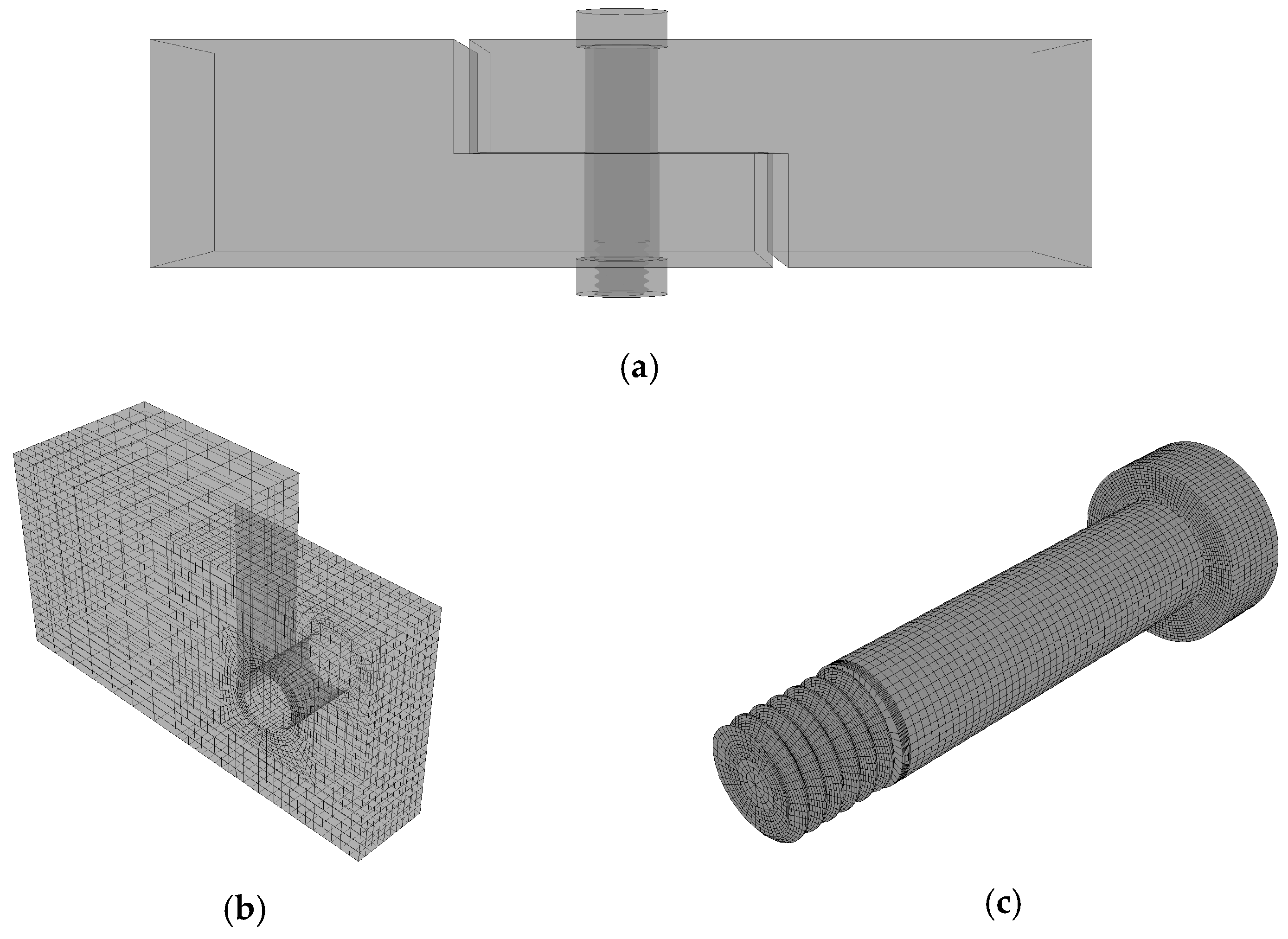
  • After the dynamic model of the bolted structure is established, it is usually transformed into an equivalent model through finite element for stress–strain calculation. In recent years, the mechanical model has been further developed. However, various assumptions in the kinetic model lead to a large deviation between the theory and reality, and there are non-uniform micro-convex bodies on the microscopic surface of the connection structure, which greatly affects the accuracy of the mechanical prediction. Wang Biao of Sun Yat-sen University addressed the above problems [111], and from the thermodynamic point of view, through the introduction of elastic and dissipative energies, the material structure was equated to a thermodynamic system, and a mechanical computational prediction that can be made under complex loading conditions. Additionally, the deformation of complex structures was established [112,113], which achieves an accurate prediction of the strength of the material failure and deformation of the material localisation. This method has proved the correctness of the method through a variety of experiments. However, how to apply this method in engineering practice still needs to be studied.

Author Contributions

X.L. and M.Z. conceived and designed this project. S.W. conducted a literature review. S.L., X.L. and M.Z. wrote and edited the manuscript. Z.X. and Y.L. reviewed and edited the manuscript. All authors have read and agreed to the published version of the manuscript.

Funding

This research received no external funding.

Data Availability Statement

Not applicable.

Conflicts of Interest

The authors declare no conflict of interest.

References

  1. Lu, X.; Zhu, M.; Liu, Y.; Wang, S.; Xu, Z.; Li, S. Triangular Position Multi-Bolt Layout Structure Optimization. Appl. Sci. 2023, 13, 8786. [Google Scholar] [CrossRef]
  2. Liu, L. Research on Remaining Life Prediction and Remanufacturability Assessment of Retired Machine Tool Spindles. Ph.D. Thesis, Northwestern Polytechnical University, Xi’an, China, 2019. [Google Scholar]
  3. Guo, F.; Bi, Y.; Zhou, G. Numerical simulation of the reduction of plate friction resistance using microbubbles. Numerical simulation of flat plate frictional resistance reduction using microbubbles. J. Nav. Eng. Univ. 2008, 20, 5. [Google Scholar]
  4. Persson, B.N.T. History of Tribology. In Encyclopedia of Lubricants and Lubrication; Mang, T., Ed.; Springer: Berlin/Heidelberg, Germany, 2014; pp. 791–797. [Google Scholar]
  5. Popov, V.L. Contact Mechanics and Friction Physical Principles and Applications; Tsinghua University Press: Beijing, China, 2016. [Google Scholar]
  6. Jost, H. Lubrication (Tribology) Education and Research; A Report on the Present Position and Industry’s Needs; Department of Education and Science, Her Majesty’s Stationary Office: London, UK, 1966. [Google Scholar]
  7. Huang, P. Tutorial on Tribology; Higher Education Press: Beijing, China, 2008. [Google Scholar]
  8. Epiphaniou, N. Modelling of Dynamic Friction across Solid Material Interfaces Using Molecular Dynamics Techniques. Ph.D. Thesis, Cranfield University, Bedford, UK, 2010. [Google Scholar]
  9. Tomlinson, G.A.C.V.I. A molecular theory of friction. Lond. Edinb. Dublin Philos. Mag. J. Sci. 1929, 7, 905–939. [Google Scholar] [CrossRef]
  10. Kragelsky, I.V.; Dobychin, M.N.; Kombalov, V.S. Friction and Wear: Calculation Methods; Elsevier: Amsterdam, The Netherlands, 2013. [Google Scholar]
  11. Bowden, F.P. The Friction and Lubrication of Solids. Am. J. Phys. 1951, 19, 428. [Google Scholar] [CrossRef]
  12. Bhushan, B.; Israelachvili, J.N.; Landman, U. Nanotribology: Friction, wear and lubrication at the atomic scale. Nature 1995, 374, 607–616. [Google Scholar] [CrossRef]
  13. Zou, K.; Li, Z.; Leng, Y.; Chen, J.; Hu, Y.; Wang, H.; Wen, S. Surface force meter and its application in surface contact study. Sci. Bull. 1999, 44, 992–995. [Google Scholar] [CrossRef]
  14. Wen, S. Advances in Nano Tribology Research. J. Mech. Eng. 2007, 43, 8. [Google Scholar]
  15. Granick, S.; Demirel, A.L.; Cai, L.L.; Peanasky, J. Soft Matter in a Tight Spot: Nanorheology of Confined Liquids and Block Copolymers. Isr. J. Chem. 2013, 35, 75–84. [Google Scholar] [CrossRef]
  16. Zou, K.; Hu, Y.; Wen, S. Surface Force Apparatus (SFA) and its application to molecular tribology. In Advances in Nano Tribology; Tsinghua University: Beijing, China, 1995; pp. 55–61. [Google Scholar]
  17. Homola, A.M.; Israelachvili, J.N.; McGuiggan, P.M.; Gee, M.L. Fundamental experimental studies in tribology: The transition from “interfacial” friction of undamaged molecularly smooth surfaces to “normal” friction with wear. Wear 1990, 136, 65–83. [Google Scholar] [CrossRef]
  18. Homola, A.; Israelachvili, J.; Gee, M.; McGuiggan, P. Measurements of and Relation between the Adhesion and Friction of Two Surfaces Separated by Molecularly Thin Liquid Films. J. Tribol. 1989, 111, 675–682. [Google Scholar] [CrossRef]
  19. Tabor, D. Tribology—The last 25 years A personal view. Tribol. Int. 1995, 28, 7–10. [Google Scholar] [CrossRef]
  20. Ding, Q.; Zhai, H. Advances in friction dynamics of mechanical systems. Prog. Mech. 2013, 43, 112–131. [Google Scholar]
  21. Gaul, L.; Nitsche, R. The Role of Friction in Mechanical Joints. Appl. Mech. Rev. 2001, 54, 93–106. [Google Scholar] [CrossRef]
  22. Oden, J.; Martins, J. Models and computational methods for dynamic friction phenomena. Comput. Methods Appl. Mech. Eng. 1985, 52, 527–634. [Google Scholar] [CrossRef]
  23. Zhang, X. Structural Nonlinear Dynamics of Friction Connections. Ph.D. Thesis, Harbin Institute of Technology, Harbin, China, 2013. [Google Scholar]
  24. Segalman, D.J. An Initial Overview of Iwan Modeling for Mechanical Joints; Sandia National Lab. (SNL-NM): Albuquerque, NM, USA, 2001. [Google Scholar]
  25. Armstrong-Hélouvry, B. Control of Machines with Friction. J. Tribol. 1992. [Google Scholar] [CrossRef]
  26. Janiec, M. Friction Compensation by the Use of Friction Observer. Master’s Thesis, Lund Institute of Technology, Lund, Sweden, 2004. [Google Scholar]
  27. Zhu, J. Research progress of friction modeling in mechanical systems. Jifu Times 2016, 262–266. [Google Scholar]
  28. Morin, A.J. New friction experiments carried out at Metz in 1831–1833. Proc. Fr. R. Acad. Sci. 1833, 4, 128. [Google Scholar]
  29. Bo, L.C.; Pavelescu, D. The friction-speed relation and its influence on the critical velocity of stick-slip motion. Wear 1982, 82, 277–289. [Google Scholar]
  30. Karnopp, D. Computer Simulation of Stick-Slip Friction in Mechanical Dynamic Systems. Trans. ASME J. Dyn. Syst. Meas. Control 1985, 107, 100–103. [Google Scholar] [CrossRef]
  31. Iurian, C.; Ikhouane, F.; Rodellar Benedé, J.; Griñó Cubero, R. Identification of a System with Dry Friction; Universitat Politecnicade Catalunya: Barcelona, Spain, 2005. [Google Scholar]
  32. Ravanbod-Shirazi, L.; Besançon-Voda, A. Friction identification using the Karnopp model, applied to an electropneumatic actuator. Proc. Inst. Mech. Eng. Part I J. Syst. Control Eng. 2003, 217, 123–138. [Google Scholar] [CrossRef]
  33. Armstrong-Hélouvry, B.; Dupont, P.; De Wit, C.C. A survey of models, analysis tools and compensation methods for the control of machines with friction. Automatica 1994, 30, 1083–1138. [Google Scholar] [CrossRef]
  34. Buczkowski, R.; Kleiber, M. Statistical models of rough surfaces for finite element 3D-contact analysis. Arch. Comput. Methods Eng. 2009, 16, 399–424. [Google Scholar] [CrossRef]
  35. Yang, G.; Xiong, M.; Hong, J.; Liu, H.; Wang, F. Digital representation and contact characteristics analysis of 3D rough surfaces. J. Xi’an Jiaotong Univ. 2012, 46, 6. [Google Scholar]
  36. Wu, S.; Feng, Y.; Wu, K.; Shi, X.; Wang, C.; Wang, W. Construction and simulation analysis of a three-dimensional rough surface electrical contact model based on finite element analysis. J. Hefei Univ. Technol. Nat. Sci. Ed. 2018, 41, 1441–1445. [Google Scholar]
  37. Wei, B.; Sun, K.; Wang, Y.; Fang, L.; Chen, C. Research on finite element simulation calculation of high-speed dry sliding friction coefficient. J. Xi’an Jiaotong Univ. 2020, 54, 82–89. [Google Scholar]
  38. Wu, W.; Lu, Y. Simulation research on normal contact stiffness of rough surface in turning. China Test 2021, 47, 163–168. [Google Scholar]
  39. Dahl, P. Solid friction damping of spacecraft oscillations. In Proceedings of the Guidance and Control Conference, Boston, MA, USA, 20–22 August 1975. [Google Scholar]
  40. Dahl, P.R. Solid friction damping of mechanical vibrations. AIAA J. 1976, 14, 1675–1682. [Google Scholar] [CrossRef]
  41. Haessig, D.A., Jr.; Friedland, B. On the Modeling and Simulation of Friction. J. Dyn. Syst. Meas. Control 1991, 113, 354–362. [Google Scholar] [CrossRef]
  42. de Wit, C.C.; Olsson, H.; Astrom, K.J.; Lischinsky, P. A new model for control of systems with friction. IEEE Trans. Autom. Control 1995, 40, 419–425. [Google Scholar] [CrossRef]
  43. Cohn, S. Dynamic Friction Measurement, Modeling, and Compensation for Precise Motion Control. Master’s Thesis, New Jersey Institute of Technology, Department of Mechanical Engineering, Newark, NJ, USA, 1998. [Google Scholar]
  44. Barahanov, N.; Ortega, R. Necessary and sufficient conditions for passivity of the LuGre friction model. IEEE Trans. Autom. Control 2000, 45, 830–832. [Google Scholar] [CrossRef]
  45. Hanss, M.; Oexl, S.; Gaul, L. Identification of a bolted-joint model with fuzzy parameters loaded normal to the contact interface. Mech. Res. Commun. 2002, 29, 177–187. [Google Scholar] [CrossRef]
  46. Lenz, J.; Gaul, L. The influence of microslip on the dynamic behavior of bolted joints. In Proceedings-SPIE the International Society for Optical Engineering; SPIE International Society for Optical: Bellingham, WA, USA, 1995; p. 248. [Google Scholar]
  47. Swevers, J.; Al-Bender, F.; Ganseman, C.G.; Projogo, T. An integrated friction model structure with improved presliding behavior for accurate friction compensation. IEEE Trans. Autom. Control 2000, 45, 675–686. [Google Scholar] [CrossRef]
  48. Lampaert, V.; Swevers, J.; Al-Bender, F. Modification of the Leuven integrated friction model structure. IEEE Trans. Autom. Control 2002, 47, 683–687. [Google Scholar] [CrossRef]
  49. Abad, J.; Medel, F.; Franco, J.M. Determination of Valanis model parameters in a bolted lap joint: Experimental and numerical analyses of frictional dissipation. Int. J. Mech. Sci. 2014, 89, 289–298. [Google Scholar] [CrossRef]
  50. Jalali, H.; Ahmadian, H.; Pourahmadian, F. Identification of micro-vibro-impacts at boundary condition of a nonlinear beam. Mech. Syst. Signal Process. 2011, 25, 1073–1085. [Google Scholar] [CrossRef]
  51. Valanis, K.C. Fundamental Consequences of a New Intrinsic Time Measure: Plasticity as a Limit of the Endochronic Theory. Arch. Mech. 1980, 32–68. [Google Scholar]
  52. Chu, Y. Modeling and Identification of Nonlinear Bolted Joint Structures. Master’s Thesis, Nanjing University of Aeronautics and Astronautics, Nanjing, China, 2017. [Google Scholar]
  53. Iwan, W.D. A Distributed-Element Model for Hysteresis and Its Steady-State Dynamic Response. J. Appl. Mech. 1966, 33, 893–900. [Google Scholar] [CrossRef]
  54. Ramberg, W.; Osgood, W.R. Description of Stress-Strain Curves by Three Parameters; Technical Note; National Advisory Committee for Aeronautics: Boston, MA, USA, 1943. [Google Scholar]
  55. Wentzel, H. Modelling of Frictional Joints in Dynamically Loaded Structrues: A Review; KTH Solid Mechanics, Royal Institute of Technology: Stockholm, Sweden, 2006. [Google Scholar]
  56. Segalman, D.J.; Starr, M.J. Relationships among Certain Joint Constitutive Models; Sandia National Laboratories: Albuquerque, NM, USA, 2004. [Google Scholar]
  57. Song, Y.; Hartwigsen, C.; McFarland, D.; Vakakis, A.F.; Bergman, L. Simulation of dynamics of beam structures with bolted joints using adjusted Iwan beam elements. J. Sound. Vib. 2004, 273, 249–276. [Google Scholar] [CrossRef]
  58. Rajaei, M.; Ahmadian, H. Development of generalized Iwan model to simulate frictional contacts with variable normal loads. Appl. Math. Model. 2014, 38, 4006–4018. [Google Scholar] [CrossRef]
  59. Segalman, D.J. A Four-Parameter Iwan Model for Lap-Type Joints. J. Appl. Mech. 2005, 72, 752–760. [Google Scholar] [CrossRef]
  60. Li, Y.; Hao, Z. A six-parameter Iwan model and its application. Mech. Syst. Signal Process. 2016, 68, 354–365. [Google Scholar] [CrossRef]
  61. Li, D.; Botto, D.; Xu, C.; Gola, M. A new approach for the determination of the Iwan density function in modeling friction contact. Int. J. Mech. Sci. 2020, 180, 105671. [Google Scholar] [CrossRef]
  62. Wang, S.; Zhu, M.; Cao, H.; Xie, X.; Li, B.; Guo, M.; Li, H.; Xu, Z.; Tian, J.; Ma, D. Contact Pressure Distribution and Pressure Correction Methods of Bolted Joints under Mixed-Mode Loading. Coatings 2022, 12, 1516. [Google Scholar] [CrossRef]
  63. Wang, S.-A.; Zhu, M.; Xie, X.; Li, B.; Liang, T.-X.; Shao, Z.-Q.; Liu, Y.-L. Finite Element Analysis of Elastoplastic Elements in the Iwan Model of Bolted Joints. Materials 2022, 15, 5817. [Google Scholar] [CrossRef] [PubMed]
  64. Wang, S.; Zhu, M.; Xu, Z.; Wu, F.; Li, B.; Shao, Z.; Cao, H. A stiffness degradation model of bolted joint based on fourth polynomial pressure distribution. AIP Adv. 2021, 11. [Google Scholar] [CrossRef]
  65. Liu, B.; Dong, X.; Peng, Z. Nonlinear equivalent modeling of bolted joints based on the Iwan model. Noise Vib. Control 2020, 40, 7–12. [Google Scholar]
  66. Zhu, M.; Miao, H.; Li, B. Nonlinear contact modeling and parameter identification of bolts based on Iwan model. Sci. Technol. Eng. 2022, 22, 14729–14735. [Google Scholar]
  67. Al-Bender, F.; Lampaert, V.; Swevers, J. Modeling of dry sliding friction dynamics: From heuristic models to physically motivated models and back. Chaos Interdiscip. J. Nonlinear Sci. 2004, 14, 446–460. [Google Scholar] [CrossRef] [PubMed]
  68. Al-Bender, F.; Lampaert, V.; Swevers, J. A novel generic model at asperity level for dry friction force dynamics. Tribol. Lett. 2004, 16, 81–93. [Google Scholar] [CrossRef]
  69. Hess, D.; Soom, A. Friction at a Lubricated Line Contact Operating at Oscillating Sliding Velocities. J. Tribol. 1990, 112, 147–152. [Google Scholar] [CrossRef]
  70. Armstrong-Helouvry, B. Stick slip and control in low-speed motion. IEEE Trans. Autom. Control 1993, 38, 1483–1496. [Google Scholar] [CrossRef]
  71. Iwan, W.D. On a Class of Models for the Yielding Behavior of Continuous and Composite Systems. J. Appl. Mech. 1967, 34, 612–617. [Google Scholar] [CrossRef]
  72. Bliman, P.-A.; Sorine, M. Easy-to-use realistic dry friction models for automatic control. In Proceedings of the 3rd European Control Conference, Rome, Italy, 5–8 September 1995. [Google Scholar]
  73. Bouc, R. Forced vibrations of mechanical systems with hysteresis. In Proceedings of the Fourth Conference on Nonlinear Oscillations, Prague, Czech Republic, 5–9 September 1967. [Google Scholar]
  74. Wen, Y. Methods of Random Vibration for Inelastic Structures. Appl. Mech. Rev. 1989, 42, 39–52. [Google Scholar] [CrossRef]
  75. Menq, C.H.; Griffin, J.H. A Comparison of Transient and Steady State Finite Element Analyses of the Forced Response of a Frictionally Damped Beam. J. Vib. Acoust. 1985, 107, 19–25. [Google Scholar] [CrossRef]
  76. Menq, C.-H.; Griffin, J.; Bielak, J. The influence of microslip on vibratory response, part II: A comparison with experimental results. J. Sound. Vib. 1986, 107, 295–307. [Google Scholar] [CrossRef]
  77. Menq, C.H.; Bielak, J.; Griffin, J.H. The influence of microslip on vibratory response, part I: A new microslip model. J. Sound. Vib. 1986, 107, 279–293. [Google Scholar] [CrossRef]
  78. Müller, C.; Müser, M.H.; Carbone, G.; Menga, N. Significance of Elastic Coupling for Stresses and Leakage in Frictional Contacts. Phys. Rev. Lett. 2023, 131, 156201. [Google Scholar] [CrossRef] [PubMed]
  79. Menga, N.; Carbone, G.; Dini, D. Exploring the effect of geometric coupling on friction and energy dissipation in rough contacts of elastic and viscoelastic coatings. J. Mech. Phys. Solids 2021, 148, 104273. [Google Scholar] [CrossRef]
  80. Menga, N.; Afferrante, L.; Demelio, G.; Carbone, G. Rough contact of sliding viscoelastic layers: Numerical calculations and theoretical predictions. Tribol. Int. 2018, 122, 67–75. [Google Scholar] [CrossRef]
  81. Menga, N.; Carbone, G.; Dini, D. Do uniform tangential interfacial stresses enhance adhesion? J. Mech. Phys. Solids 2018, 112, 145–156. [Google Scholar] [CrossRef]
  82. Menga, N. Rough frictional contact of elastic thin layers: The effect of geometrical coupling. Int. J. Solids Struct. 2019, 164, 212–220. [Google Scholar] [CrossRef]
  83. Greenwood, J.A.; Williamson, J.B.P. Contact of nominally flat surfaces. Proc. R. Soc. Lond. A 1966, 295, 300–319. [Google Scholar]
  84. Chang, W.-R.; Etsion, I.; Bogy, D. An Elastic-Plastic Model for the Contact of Rough Surfaces. J. Tribol. Trans. ASME 1987, 257–263. [Google Scholar] [CrossRef]
  85. Kogut, L.; Etsion, I. Elastic-plastic contact analysis of a sphere and a rigid flat. J. Appl. Mech. 2002, 69, 657–662. [Google Scholar] [CrossRef]
  86. Kogut, L.; Etsion, I. A semi-analytical solution for the sliding inception of a spherical contact. J. Trib. 2003, 125, 499–506. [Google Scholar] [CrossRef]
  87. Kogut, L.; Etsion, I. A static friction model for elastic-plastic contacting rough surfaces. J. Trib. 2004, 126, 34–40. [Google Scholar] [CrossRef]
  88. Brizmer, V.; Kligerman, Y.; Etsion, I. A model for junction growth of a spherical contact under full stick condition. J. Tribol. 2007, 129, 783–790. [Google Scholar] [CrossRef]
  89. Brizmer, V.; Kligerman, Y.; Etsion, I. Elastic–plastic spherical contact under combined normal and tangential loading in full stick. Tribol. Lett. 2007, 25, 61–70. [Google Scholar] [CrossRef]
  90. Cohen, D.; Kligerman, Y.; Etsion, I. A model for contact and static friction of nominally flat rough surfaces under full stick contact condition. J. Tribol. 2008, 130, 031401. [Google Scholar] [CrossRef]
  91. Cohen, D.; Kligerman, Y.; Etsion, I. The effect of surface roughness on static friction and junction growth of an elastic-plastic spherical contact. J. Tribol. 2009, 131, 021404. [Google Scholar] [CrossRef]
  92. Greenwood, J.A.; Tripp, J.H. The Elastic Contact of Rough Spheres. J. Appl. Mech. 1967, 34, 153–159. [Google Scholar] [CrossRef]
  93. Greenwood, J.A.; Tripp, J. The contact of two nominally flat rough surfaces. Proc. Inst. Mech. Eng. 1970, 185, 625–633. [Google Scholar] [CrossRef]
  94. Whitehouse, D.J.; Archard, J. The properties of random surfaces of significance in their contact. Proc. R. Soc. Lond. A Math. Phys. Sci. 1970, 316, 97–121. [Google Scholar]
  95. Jackson, R.L.; Green, I. A Finite Element Study of Elasto-Plastic Hemispherical Contact Against a Rigid Flat. J. Tribol. 2005, 127, 343–354. [Google Scholar] [CrossRef]
  96. Nayak, P.R. Random Process Model of Rough Surfaces. J. Tribol. 1971, 93, 398–407. [Google Scholar] [CrossRef]
  97. Nayak, P.R. Random process model of rough surfaces in plastic contact. Wear 1973, 26, 305–333. [Google Scholar] [CrossRef]
  98. Zhao, Y.; Maietta, D.M.; Chang, L. An asperity microcontact model incorporating the transition from elastic deformation to fully plastic flow. J. Tribol. 2000, 122, 86–93. [Google Scholar] [CrossRef]
  99. Mandelbrot, B. How long is the coast of Britain? Statistical self-similarity and fractional dimension. Science 1967, 156, 636–638. [Google Scholar] [CrossRef]
  100. Mandelbrot, B.B. The Fractal Geometry of Nature; WH Freeman: New York, NY, USA, 1982. [Google Scholar]
  101. Majumdar, A.; Bhushan, B. Fractal model of elastic-plastic contact between rough surfaces. J. Tribol. 1991, 113, 1–11. [Google Scholar] [CrossRef]
  102. Wang, S.; Komvopoulos, K. A fractal theory of the interfacial temperature distribution in the slow sliding regime: Part I—Elastic contact and heat transfer analysis. J. Tribol. 1994, 116, 812–822. [Google Scholar] [CrossRef]
  103. Cao, H.; Zhu, M.; Li, B.; Lu, X.; Li, H.; Guo, M.; Wu, F.; Xu, Z. Theoretical Study of the Friction Coefficient in the MB Model. Coatings 2022, 12, 1386. [Google Scholar] [CrossRef]
  104. Sheng, X.; Luo, J.; Wen, S. Prediction of static friction coefficient based on fractal contact. China Mech. Eng. 1998, 9, 3. [Google Scholar]
  105. Zhang, X.; Wen, S.; Xu, G.; Ni, R. Study on fractal model of tangential contact stiffness of joint. Chin. J. Appl. Mech. 2003, 20, 70–72. [Google Scholar]
  106. Zhu, M.; Lu, X.; Li, H.; Cao, H.; Wu, F. Applicability Analysis of Nickel Steel Plate Friction Coefficient Model Based on Fractal Theory. Coatings 2023, 13, 1096. [Google Scholar] [CrossRef]
  107. Persson, B.N.J. Contact mechanics for randomly rough surfaces. Surf. Sci. Rep. 2006, 61, 201–227. [Google Scholar] [CrossRef]
  108. Persson, B.N.J. Elastoplastic contact between randomly rough surfaces. Phys. Rev. Lett. 2001, 87, 116101. [Google Scholar] [CrossRef] [PubMed]
  109. Persson, B.N.J. Theory of rubber friction and contact mechanics. J. Chem. Phys. 2001, 115, 3840–3861. [Google Scholar] [CrossRef]
  110. Tiwari, A.; Almqvist, A.; Persson, B.N.J. Plastic Deformation of Rough Metallic Surfaces. Tribol. Lett. 2020, 68, 1–12. [Google Scholar] [CrossRef]
  111. Wang, B. Thermodynamic strength theory. Adv. Mech. 2023, 53, 693–712. [Google Scholar]
  112. Hu, Y.; Chen, J.; Wang, B. Global nonequilibrium energy criterion for predicting strength of 316L stainless steel under complex loadings: Theoretical modeling and experimental validation. Sci. China Phys. Mech. Astron. 2022, 65, 244611. [Google Scholar] [CrossRef]
  113. Wang, B. A general thermodynamic theory for predicting the failure property of material structures with complex loadings. Eng. Fract. Mech. 2021, 254, 107936. [Google Scholar] [CrossRef]
Figure 1. Bolted connection. (a) Four stages. (b) Bolt. (c) Slab.
Lubricants 12 00182 g001
Figure 2. Relationship between bolt and flat plate.
Lubricants 12 00182 g002
Figure 3. Finite element model. (a) Assembly drawing. (b) Flat grid. (c) Bolt mesh.
Lubricants 12 00182 g003
Figure 4. Dahl model.
Lubricants 12 00182 g004
Figure 5. Model of muttonchops.
Lubricants 12 00182 g005
Figure 6. Valanis model working principle.
Lubricants 12 00182 g006
Figure 7. Iwan model.
Lubricants 12 00182 g007
Figure 8. Hysteresis loop of Iwan model.
Lubricants 12 00182 g008
Figure 9. Iwan model density function.
Lubricants 12 00182 g009
Figure 10. Improving the Iwan model.
Lubricants 12 00182 g010
Figure 11. GW model.
Lubricants 12 00182 g011
Figure 12. Finite element modelling of GW model.
Lubricants 12 00182 g012
Figure 13. Microscopic rough surface contact force.
Lubricants 12 00182 g013
Figure 14. Contact modelling under mixed loads [88].
Lubricants 12 00182 g014
Disclaimer/Publisher’s Note: The statements, opinions and data contained in all publications are solely those of the individual author(s) and contributor(s) and not of MDPI and/or the editor(s). MDPI and/or the editor(s) disclaim responsibility for any injury to people or property resulting from any ideas, methods, instructions or products referred to in the content.

