Mechanical and Tribological Behavior of Nitrided AISI/SAE 4340 Steel Coated with NiP and AlCrN

 ,
,  , , , ,
Abstract
:1. Introduction
2. Experimental Procedures
- Preparation of specimens: Several 5 mm disc specimens were obtained by cutting a 25 mm diameter AISI/SAE 4340 bar. These specimens served as the base material for the coating system investigation.
- Heat treatment: The steel specimens underwent heat treatment processes, including quenching and tempering (Q/T). This treatment optimized the mechanical properties of the specimens to ensure consistent and reliable results.
- Plasma nitriding: After the Q/T process, the quenched and tempered samples were subjected to plasma nitriding.
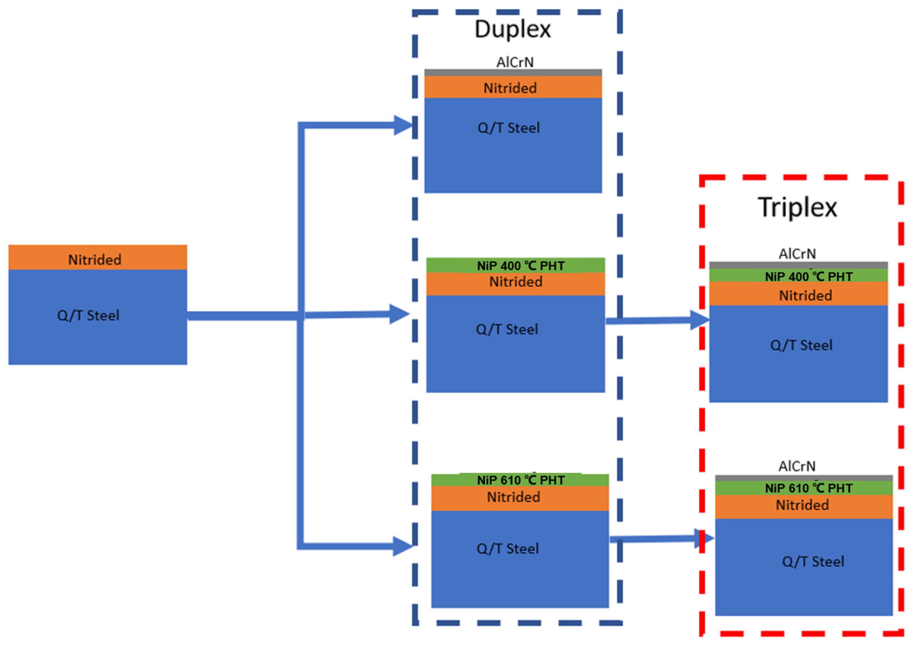
- Duplex architecture 1 (AlCrN on nitrided steel): In this architecture, an approximately 3-micrometer-thick AlCrN coating was directly deposited onto the nitrided steel specimens. This architecture aimed to evaluate the tribological performance of the AlCrN coating on a nitrided substrate.
- Duplex architecture 2 and 3 (NiP on nitrided steel): In the second and third architectures, a 30-micrometer-thick NiP coating was deposited onto the nitrided substrates. Subsequently, interdiffusion post-heat treatment (IPHT) was performed at 400 °C or 610 °C. These architectures aimed to assess the effect of the IPHT temperature on the mechanical and tribological properties of the NiP coating.
- Triplex architecture 4 and 5 (AlCrN on NiP on nitrided steel): In the fourth and fifth architectures, an AlCrN coating was deposited using the cathodic arc evaporation (CAE) technique onto the NiP-coated substrates, which had undergone IPHT at 400 °C or 610 °C. These architectures aimed to investigate the influence of the IPHT on the ability of the NiP deposit to provide mechanical support for the AlCrN coating and enhance its wear resistance.
2.1. Steel Heat Treatment and Nitriding
2.2. Electroless Nickel Deposition Process and AlCrN Coating
2.3. Characterization Techniques
2.3.1. Microstructural Characterization
2.3.2. Hardness and Elastic Modulus Determination
2.3.3. Adhesion Tests
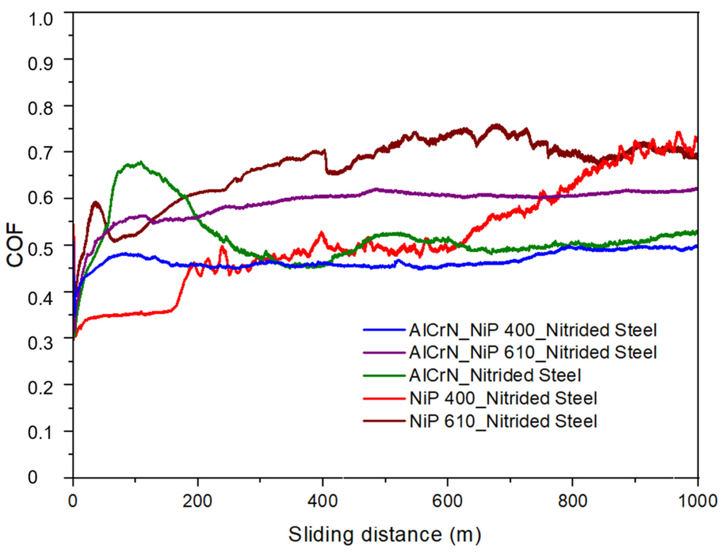
2.3.4. Tribological Tests
3. Results and Discussion
4. Conclusions
Author Contributions
Funding
Data Availability Statement
Conflicts of Interest
References
- Henriques, C.C.D.; Joia, C.-J.B.; Guedes, F.; Baptista, I.P. Material Selection for Brazilian Presalt Fields. In Proceedings of the Offshore Technology Conference, Houston, Texas, USA, 30 April–3 May 2012; p. OTC-23320-MS. [Google Scholar] [CrossRef]
- Iannuzzi, M.; Barnoush, A.; Johnsen, R. Materials and corrosion trends in offshore and subsea oil and gas production. Npj Mater. Degrad. 2017, 1, 2. [Google Scholar] [CrossRef]
- Sudagar, J.; Lian, J.; Sha, W. Electroless nickel, alloy, composite and nano coatings—A critical review. J. Alloys Compd. 2013, 571, 183–204. [Google Scholar] [CrossRef]
- Mallory, G. The Fundamental Aspects of Electroless Nickel Plating. Electroless Plat. Fundam. Appl. 1991, 1–56. [Google Scholar]
- Fayyad, E.M.; Abdullah, A.M.; Hassan, M.K.; Mohamed, A.M.; Jarjoura, G.; Farhat, Z. Recent advances in electroless-plated Ni-P and its composites for erosion and corrosion applications: A review. Emergent Mater. 2018, 1, 3–24. [Google Scholar] [CrossRef]
- Rabizadeh, T.; Allahkaram, S.R.; Zarebidaki, A. An investigation on effects of heat treatment on corrosion properties of Ni-P electroless nano-coatings. Mater. Des. 2010, 31, 3174–3179. [Google Scholar] [CrossRef]
- Taheri, R.; Oguocha, I.N.A.; Yannacopoulos, S. The tribological characteristics of electroless NiP coatings. Wear 2001, 249, 389–396. [Google Scholar] [CrossRef]
- Keong, K.G.; Sha, W.; Malinov, S. Hardness evolution of electroless nickel-phosphorus deposits with thermal processing. Surf. Coatings Technol. 2003, 168, 263–274. [Google Scholar] [CrossRef]
- Keong, K.G.; Sha, W. Crystallisation and Phase Transformation Behaviour of Electroless Nickel-Phosphorus Deposits and Their Engineering Properties. Surf. Eng. 2002, 18, 329–343. [Google Scholar] [CrossRef]
- Ramalho, A.; Miranda, J.C. Friction and wear of electroless NiP and NiP + PTFE coatings. Wear 2005, 259, 828–834. [Google Scholar] [CrossRef]
- Zangeneh-Madar, K.; Vaghefi, S.M.M. The effect of thermochemical treatment on the structure and hardness of electroless Ni-P coated low alloy steel. Surf. Coatings Technol. 2004, 182, 65–74. [Google Scholar] [CrossRef]
- Soares, M.E.; Soares, P.; Souza, P.R.; Souza, R.M.; Torres, R.D. The effect of nitriding on adhesion and mechanical properties of electroless Ni–P coating on AISI 4140 steel. Surf. Eng. 2016, 33, 1–6. [Google Scholar] [CrossRef]
- Correia, K.S.; Greca, L.G.; Sopchenski, L.; Soares, P.; Amorim, F.L.; Torres, R.D. Strength and Deformation Properties of Low-Alloy Steel Bolts with Electroless Ni-P Coating: An Investigation of Two Thermal Routes. J. Mater. Eng. Perform. 2020, 29, 6025–6032. [Google Scholar] [CrossRef]
- Hsu, C.; Chiu, S.; Shih, Y. Effects of thickness of electroless Ni-P deposit on corrosion fatigue damage of 7075-T6 under salt spray atmosphere. Mater. Trans. 2004, 45, 3201–3208. [Google Scholar] [CrossRef]
- Hsu, C.H.; Lee, C.Y.; Chen, K.L.; Lu, J.H. Effects of CrN/EN and Cr2O3/EN duplex coatings on corrosion resistance of ADI. Thin Solid Films 2009, 517, 5248–5252. [Google Scholar] [CrossRef]
- Hudak, O.E.; Kutrowatz, P.; Wojcik, T.; Ntemou, E.; Primetzhofer, D.; Shang, L.; Ramm, J.; Hunold, O.; Kolozsv, S.; Polcik, P.; et al. Improved corrosion resistance of cathodic arc evaporated Al0.7Cr0.3−xVxN coatings in NaCl-rich media. Corros. Sci. 2023, 221, 11376. [Google Scholar] [CrossRef]
- Li, Y.Y.; Wu, F.B. Microstructure and corrosion characteristics of CrN/NiP sputtering thin films. Thin Solid Films 2010, 518, 7527–7531. [Google Scholar] [CrossRef]
- Biswas, B.; Purandare, Y.; Khan, I.; Hovsepian, P.E. Effect of substrate bias voltage on defect generation and their influence on corrosion and tribological properties of HIPIMS deposited CrN/NbN coatings. Surf. Coatings Technol. 2018, 344, 383–393. [Google Scholar] [CrossRef]
- Sanchéz, J.E.; Sanchéz, O.M.; Ipaz, L.; Aperador, W.; Caicedo, J.C.; Amaya, C.; Landaverde, M.A.H.; Beltran, F.E.; Muñoz-Saldaña, J.; Zambrano, G. Mechanical, tribological, and electrochemical behavior of Cr1−xAlxN coatings deposited by r.f. reactive magnetron co-sputtering method. Appl. Surf. Sci. 2010, 256, 2380–2387. [Google Scholar] [CrossRef]
- Petrogalli, C.; Montesano, L.; Gelfi, M.; La Vecchia, G.M.; Solazzi, L. Tribological and corrosion behavior of CrN coatings: Roles of substrate and deposition defects. Surf. Coatings Technol. 2014, 258, 878–885. [Google Scholar] [CrossRef]
- Panjan, P.; Čekada, M.; Panjan, M.; Kek-Merl, D.; Zupanič, F.; Čurković, L.; Paskvale, S. The Surface density of growth defects in different PVD hard coatings prepared by sputtering. Vacuum 2012, 86, 794–798. [Google Scholar] [CrossRef]
- Mo, J.L.; Zhu, M.H.; Leyland, A.; Matthews, A. Impact wear and abrasion resistance of CrN, AlCrN and AlTiN PVD coatings. Surf. Coatings Technol. 2013, 215, 170–177. [Google Scholar] [CrossRef]
- Liew, W.Y.H.; Jie, J.L.L.; Yan, L.Y.; Dayou, J.; Sipaut, C.S.; Madlan, M.F.B. Frictional and wear behaviour of AlCrN, TiN, TiAlN single-layer coatings, and TiAlN/AlCrN, AlN/TiN nano-multilayer coatings in dry sliding. Procedia Eng. 2013, 68, 512–517. [Google Scholar] [CrossRef]
- Ballesteros-Arguello, A.; Ramírez-Reyna, F.O.; Rodríguez-Castro, G.A.; Meneses-Amador, A.; Fernández-Valdés, D.; Reyes-Carcaño, O. Experimental and numerical evaluation of the contact fatigue resistance of AlCrN, FexN and AlCrN/FexN coatings on AISI 4140 steel. Surf. Coatings Technol. 2021, 423, 127620. [Google Scholar] [CrossRef]
- Mo, J.L.; Zhu, M.H.; Lei, B.; Leng, Y.X.; Huang, N. Comparison of tribological behaviours of AlCrN and TiAlN coatings-Deposited by physical vapor deposition. Wear 2007, 263, 1423–1429. [Google Scholar] [CrossRef]
- ASTM C 1624-22; Standard Test Method for Adhesion Strength and Mechanical Failure Modes of Ceramic Coatings by Quantitative Single Point Scratch Testing. ASTM International: West Conshohocken, PA, USA, 2022. [CrossRef]
- ASTM G99-17; Standard Test Method for Wear Testing with a Pin-on-Disk Apparatus. ASTM International: West Conshohocken, PA, USA, 2020. [CrossRef]
- Islam, M.; Azhar, M.R.; Fredj, N.; Burleigh, T.D. Electrochemical impedance spectroscopy and indentation studies of pure and composite electroless Ni-P coatings. Surf. Coatings Technol. 2013, 236, 262–268. [Google Scholar] [CrossRef]
- Sahoo, P.; Das, S.K. Tribology of electroless nickel coatings—A review. Mater. Des. 2011, 32, 1760–1775. [Google Scholar] [CrossRef]
- Rajendran, R.; Sha, W.; Elansezhian, R. Abrasive wear resistance of electroless Ni-P coated aluminium after post treatment. Surf. Coatings Technol. 2010, 205, 766–772. [Google Scholar] [CrossRef]
- Chen, J.-S.; Yu, C.; Lu, H. Phase stability, magnetism, elastic properties and hardness of binary iron nitrides from first principles. J. Alloys Compd. 2015, 625, 224–230. [Google Scholar] [CrossRef]
- Apachitei, I.; Tichelaar, F.D.; Duszczyk, J.; Katgerman, L. The effect of heat treatment on the structure and abrasive wear resistance of autocatalytic NiP and NiP–SiC coatings. Surf. Coatings Technol. 2002, 149, 263–278. [Google Scholar] [CrossRef]
- Malfatti, C.F.; Veit, H.M.; Santos, C.B.; Metzner, M.; Hololeczek, H.; Bonino, J.P. Heat treated NiP-SiC composite coatings: Elaboration and tribocorrosion behaviour in NaCl solution. Tribol. Lett. 2009, 36, 165–173. [Google Scholar] [CrossRef]
- Reiter, A.E.; Derflinger, V.H.; Hanselmann, B.; Bachmann, T.; Sartory, B. Investigation of the properties of Al1−xCrxN coatings prepared by cathodic arc evaporation. Surf. Coatings Technol. 2005, 200, 2114–2122. [Google Scholar] [CrossRef]
- Ramírez-Reyna, F.O.; Rodríguez-Castro, G.A.; Figueroa-López, U.; Morón, R.C.; Arzate-Vázquez, I.; Meneses-Amador, A. Effect of nitriding pretreatment on adhesion and tribological properties of AlCrN coating. Mater. Lett. 2021, 284, 128931. [Google Scholar] [CrossRef]
- Kumar, A.; Li, D.Y. Can the H/E ratio be generalized as an index for the wear resistance of materials? Mater. Chem. Phys. 2022, 275, 125245. [Google Scholar] [CrossRef]


| Architecture of Coatings | Roughness, Ra (µm) |
|---|---|
| AlCrN-NiP400-Nitrided Steel | 0.19 ± 0.01 |
| AlCrN-NiP610-Nitrided Steel | 0.21 ± 0.04 |
| NiP400-Nitrided Steel | 0.23 ± 0.07 |
| NiP610-Nitrided Steel | 0.31 ± 0.03 |
| AlCrN-Nitrided Steel | 0.15 ± 0.02 |
| Layer Architecture | H (GPa) | E (GPa) | H/E |
|---|---|---|---|
| Nitrided Steel | 6.62 ± 0.31 | 262 ± 5 | 0.025 ± 0.0012 |
| NiP 400/Nitrided Steel | 14.67 ± 1.26 | 227 ± 9 | 0.064 ± 0.003 |
| NiP 610/Nitrided Steel | 11.00 ± 3.74 | 206 ± 27 | 0.053 ± 0.016 |
| AlCrN/Nitrided Steel | 35.50 ± 4.80 | 353 ± 38 | 0.100 ± 0.013 |
| AlCrN/NiP 400/Nitrided Steel | 34.88 ± 4.13 | 348 ± 29 | 0.099 ± 0.0038 |
| AlCrN/NiP 610/Nitrided Steel | 30.79 ± 3.79 | 338 ± 41 | 0.091 ± 0.0074 |
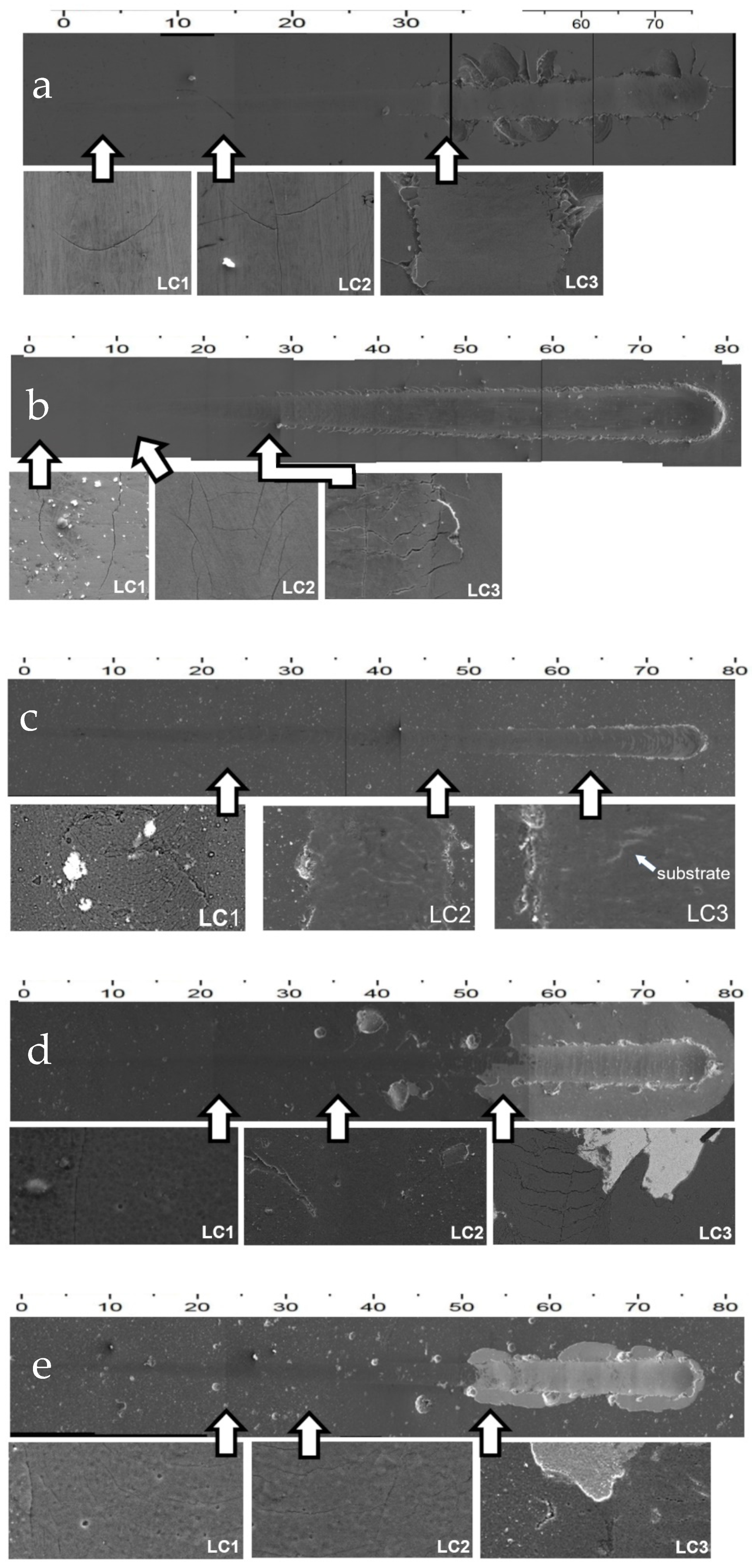
| Architecture | Lc1 (N) | Failure Mode | Lc2 (N) | Failure Mode | Lc3 (N) | Failure Mode |
|---|---|---|---|---|---|---|
| NiP IPHT 400 °C | 3.0 | arc tensile cracks | 14.0 | chevron tensile cracks | 33.5 | wedging spallation |
| NiP IPHT 610 °C | 1.0 | lateral cracks | 10.0 | chevron tensile cracks | 28.0 | wedging spallation |
| AlCrN/Nitrided Steel | 22.5 | conformal cracks | 46.0 | recovery spallation | 63.0 | buckling spallation |
| AlCrN/NiP 400 °C Nitrided Steel | 22.0 | lateral cracks | 32.5 | chevron tensile cracks | 51.0 | gross spallation |
| AlCrN/NiP 610 °C Nitrided Steel | 25.0 | lateral cracks | 35.0 | chevron tensile cracks | 51.0 | gross spallation |
Disclaimer/Publisher’s Note: The statements, opinions and data contained in all publications are solely those of the individual author(s) and contributor(s) and not of MDPI and/or the editor(s). MDPI and/or the editor(s) disclaim responsibility for any injury to people or property resulting from any ideas, methods, instructions or products referred to in the content. |
© 2024 by the authors. Licensee MDPI, Basel, Switzerland. This article is an open access article distributed under the terms and conditions of the Creative Commons Attribution (CC BY) license (https://creativecommons.org/licenses/by/4.0/).
Share and Cite
Soares, M.E.; He, Q.; DePaiva, J.M.; de Freitas, B.M.; Soares, P.; Veldhuis, S.C.; Amorim, F.L.; Torres, R.D. Mechanical and Tribological Behavior of Nitrided AISI/SAE 4340 Steel Coated with NiP and AlCrN. Lubricants 2024, 12, 181. https://doi.org/10.3390/lubricants12050181
Soares ME, He Q, DePaiva JM, de Freitas BM, Soares P, Veldhuis SC, Amorim FL, Torres RD. Mechanical and Tribological Behavior of Nitrided AISI/SAE 4340 Steel Coated with NiP and AlCrN. Lubricants. 2024; 12(5):181. https://doi.org/10.3390/lubricants12050181
Chicago/Turabian StyleSoares, Marcos E., Qianxi He, Jose M. DePaiva, Bruna M. de Freitas, Paulo Soares, Stephen C. Veldhuis, Fred L. Amorim, and Ricardo D. Torres. 2024. "Mechanical and Tribological Behavior of Nitrided AISI/SAE 4340 Steel Coated with NiP and AlCrN" Lubricants 12, no. 5: 181. https://doi.org/10.3390/lubricants12050181