Article

Improving the Flexibility of Ship Propellers Additively Manufactured from High-Density Polyethylene/Long Carbon Fiber Composites by Prepreg Coating

1
Institute of Marine Sciences and Technology, Dokuz Eylul University, Baku Bulv. 32, Balcova, Izmir 35340, Türkiye
2
Aviation Higher Vocational School, Ege University, 1099 S. 114 Sarnic, Gaziemir, Izmir 35100, Türkiye
3
Marine, Offshore & Subsea Technology Group, School of Engineering, Newcastle University, Armstrong Building, Queen Victoria Road, Newcastle upon Tyne NE1 7RU, UK
4
Fatsa Faculty of Marine Sciences, Ordu University, Evkaf, Arslan Aydınlık Cd. 1a, Fatsa, Ordu 52400, Türkiye
*
Author to whom correspondence should be addressed.
Polymers 2024, 16(9), 1257; https://doi.org/10.3390/polym16091257
Submission received: 9 April 2024 / Revised: 26 April 2024 / Accepted: 29 April 2024 / Published: 30 April 2024
(This article belongs to the Special Issue Polymeric Materials in 3D Printing)

Abstract

:
In efforts to achieve the goal of reducing ship emissions in the fight against climate change, reducing fuel consumption by making ships lighter is stated as one of the solutions. In this study, the possibilities of making composite equivalents of propellers, which are the most complex ship elements and traditionally produced from metal materials, are investigated with the advantages of additive manufacturing, which offers a rapid production opportunity for such forms. In this way, a lighter composite propeller and, therefore, a lighter ship will be achieved, and negative environmental impacts, especially harmful emissions, will be reduced. In the study, a 1/14-scale ship propeller was produced through the material extrusion method of additive manufacturing using an HDPE composite containing long carbon fiber with a 15% weight fraction. An attempt to reduce flexibility with an epoxy-carbon fabric prepreg coating was made, as the flexibility has negative effects on the performance of the produced propeller. The propeller tunnel test showed that the applied carbon fabric epoxy prepreg helped to improve the propeller’s performance by decreasing the flexibility of the propeller and reducing the deformation at the tips. At the same time, the propeller weight was decreased by 60% compared to its metal counterparts.

Graphical Abstract

1. Introduction

The International Maritime Organization (IMO) set a strategy to force the marine industry to reduce ship-induced greenhouse gas (GHG) emissions by at least 50% by 2050 [1]. This strategy leads to a continuous demand to improve ship performance and reduce the environmental impact during the lifecycle, which can be achieved holistically. Distinctly, this comprehensive approach addresses research areas, especially hull form optimization, novel propulsion systems applications such as energy-saving devices, new regulations, energy management systems, structural optimization, including life cycle improvements, sustainable materials, and social perceptions [2,3,4]. In these areas, it has always been desired to produce ship components with sustainable lightweight materials with high specific strength, remarkable specific stiffness, and high corrosion resistance and to make life cycle improvements.
Lightweighting, which is the only way to achieve maximum efficiency with minimum consumption, has turned into a discipline under the pressure of increasing sustainability concerns. This discipline has three basic components: lightweight materials, lightweight manufacturing, and lightweight structures.
When it comes to lightweighting materials, polymer-based composites, with their applications developing day by day since the 1950s, come to mind before their metal counterparts, such as aluminum. Carbon fiber’s performance and price, which are constantly improved by material science and engineering, attract attention. Applications that historically started with the hand lay-up method turned towards faster-capability modding processes such as injection molding, compression molding, liquid molding, and thermoforming, especially in the automotive field, in the 1980s.
Efforts to reduce the cycle time by improving the process have required the development of vacuum-assisted methods, which have also achieved improvements such as better surface quality and the elimination of in-mold coatings.
Today, resin transfer molding and structural reaction injection molding methods are used for composites in which high-performance components are used, and these processes have advantages such as reducing fiber scrap, easily coping with the form complexity of the part, even better control of the part thickness, and a relatively high processing rate.
Again, today, there is an increasing trend towards production in which hybrid multiscale composites are used (for example, using carbon nanotubes in carbon fiber composites) in terms of lightweighting [5].
However, all improvements, such as new cutting technologies, new welding technologies, additive manufacturing, and memories in general, are within the scope of lightweight manufacturing.
Additive manufacturing is also very suitable for creating lightweight structures. For example, by this method, lattice structures with varying internal density are an example of newly developed lightweight structures whose many properties are superior to those of solid materials. Additionally, with this method, topological optimization that will provide the best path for force transmission can also be easily performed [6].
Manufacturing ship components made from sustainable and lightweight polymer materials such as thermoset plastics will enable the above-mentioned improvements to be achieved. In addition to the use of lightweight materials such as aluminum and polymer-based composites, the production of complex geometries without waste is also important in this context. The prominent technology today for the manufacturing of complex geometries with the help of polymers and/or polymer composites is additive manufacturing, which has become widespread with the use of 3D printers (3DAM). Producing ship components (e.g., rudders, propellers) with sustainable and lightweight materials and 3DAM is one of the research areas that has attracted attention in recent years.
One of the main problems in the marine industry today is the unsustainability of polymer-based composites consisting of thermoset plastics, which are the most widely used materials in this industry. Because of their complex internal structure, a cost-effective end-of-life alternative has not yet been developed for them, especially in terms of recycling [7,8,9,10]. The marine industry, where thermoset composites are widely used, faces two important challenges: (1) creating end-of-life alternatives for vehicles that will not have a negative impact on the environment and (2) rapidly finding new sustainable materials and production methods due to legislation requiring the appropriate reuse or recycling of all engineering materials and products [11]. Relatively recent environmental legislation, such as EU directives for end-of-life vehicles [12] and waste electric and electronic equipment [13], requires sustainable end-of-life alternatives to thermoset plastics. By 2050, in the European Commission’s Plastics in a Circular Economy Strategy, it is stated that all plastics and composite wastes should be reused or recycled [14].
As is known, due to technological and economic difficulties, the recycling of thermoset plastics almost entirely consists of incrimination to obtain energy, resulting in no or little fiber recovery. However, although mechanical, chemical, and thermal energy conversion methods have been extensively researched for these materials, there is no widespread commercialization in this field yet.
For this reason, on a global scale, the increasing amount of unhandled end-of-life composites is directing the marine industry towards thermoplastic composites that are easily recycled by thermal methods. In the literature, there are studies on the environmental effects of composites containing new thermoplastic resins, especially on the ease of recycling and the behavior of recycled composites. For example, in a study conducted by Allagui et al. [15], it was observed that after recycling a composite produced from Elium, an innovative resin, and flax, a natural fiber, the elasticity modulus of the new composite improved while the failure properties and lifespan decreased. Additionally, in a study conducted by Sam-Daliri et al. [16], the optimization of filament and product production from glass fiber-reinforced polypropylene composite waste for material extrusion using the 3D printing method was studied.
Among the thermoplastic counterparts, high-density polyethylene (HDPE) stands out for its compatibility with marine environmental conditions, such as the following:
-
Resistance to moisture and the corrosive effect of the seawater;
-
Not allowing marine microorganism growth on surfaces in contact with the sea;
-
High UV stability;
-
Endurance under cycling loads (high fatigue strength);
-
High toughness [17].
Due to the mentioned advantages, the use of HDPE in the manufacturing of many products in the marine industry, such as underwater pipes and cables, piers, small work boats, geomembranes, and cages in aquaculture farms, is becoming widespread. The most popular manufacturing methods for these products are injection molding, hot-press and material extrusion printing, and, as of recently, vacuum-assisted resin transfer molding for Elium thermoplastic resin. Since it is possible to use HDPE in 3DAM in the forms of filament, powder, and pellets, these types of production encountered are limited to some experimental studies rather than large-scale industrial applications [18,19].
One of the main reasons for the inadequacies in the use of HDPE in 3DAM is its poor printability using the material extrusion (MEX) method. In previous studies on the improvement of the printability of HDPE, it has been stated that HDPE filaments have poor adhesion to the printing surface due to their low surface energy, leading to weak interlayer bonding, warping complications during printing, and stiffness limitations compared to other engineering plastics such as PA and ABS [20]. In a study by Schirmeister et al. [19], it is noted that the printing temperature of HDPE should be kept appropriate with the help of a closed chamber, and the correct adhesive should be used in the print bed. Similarly, in a study by Jagannathan et al. [21], the printer setting, the quality of HDPE’s material properties, and the regulation of material flow were given as the key elements of HDPE’s printability and achieving a smooth product surface.
In studies carried out to improve the printability of polymer filaments, the addition of macro- and microfibers and nanoparticles comes to the forefront. In this context, glass fiber, which is affordable in cost and provides relatively moderate strength, and carbon fiber, which is relatively high in cost but provides high strength and stiffness, are preferred in new filament products, especially in industries such as the aerospace and automotive industries, where the goal is to achieve lightweight and durable structures such as car chassis, aircraft wings, frames, stringers, etc. [22,23,24,25].
Furthermore, lighter structures for the same product can be achieved thanks to the material extrusion method, which allows for thicker and more flexible blades, improving hydrodynamic performance by raising cavitation inception speeds [26]. Most sustainable material research focuses on the structural design of a plate, beam, or aircraft wing [27,28] with a mechanical performance analysis [29], failure analysis [30], optimization [31], and impact damage assessment [32]. Research on 3DAM for wing structures is focused on aircraft wings [33,34,35,36] rather than ship propellers, whose geometry is more complicated. Only Herath et al. [37] have used hydrofoil geometry in their study, but some modifications were made to the wing geometry since the geometry was not suitable for production with composite material.
In this study, a ship propeller geometry is selected as a case study that focuses specifically on sustainable materials and manufacturing systems since it is one of the fundamental components of a ship and is operated in challenging conditions such as under heavy loads and in corrosive and erosive environments. Carbon-reinforced HDPE and its coated version as sustainable polymer composites and the Fused Filament Fabrication (FFF), also known as Fused Deposition Modeling (FDM), of 3DAM as a sustainable option in the production of products with complex geometry were chosen. Experiments and numerical analyses were also performed to investigate the load-dependent deformation behavior of the blades, whose geometry was chosen to be more suitable for 3DAM [38,39].
The experimental work presented here was conducted at the Emerson Cavitation Tunnel (ECT) at Newcastle University. The results show the promising hydromechanical performance of the composite ship propeller model studied.

2. Materials and Methods

2.1. HDPE/Short Carbon Fiber Composite and Its Filament

HDPE containing 15% carbon fiber reinforcement by weight was used as the composite from which the propeller was to be produced. In fact, in studies by Hu et al. [40] and Olesik et al. [41], it is shown that both the mechanical and thermal qualities of HDPE-based composites can be improved by adding 15% reinforcement material by weight.
Extrusion and printing parameters were selected after a careful review of the relevant literature [19,20,21]. Dowaksa company’s AC4102-coded carbon fibers products (Yalova, Türkiye) whose 7 μm diameter, 6 mm fiber length; density of 1.73 g·cm−3 with tensile strength and modulus are 4200 MPa and 240 GPa, respectively were used as a reinforcement material. For composite production in pellet form, a 20 mm twin-screw extruder from Labtech Engineering (Samutprakarn, Thailand) was used. Arya Company’s (Izmir, Turkey) single-screw extruder, lab type, was used for filament production.

2.2. Prepreg Composite

A commercially available product, Kordsa’s TW245 TR30S 3K prepreg carbon epoxy fibers with an areal weight of 245 gr·m−2, was used to coat the surfaces of the propellers. The catalog values of the prepreg composite are given in Table 1. Prepregs were supplied in a cold chain.

2.3. Propeller and Its Manufacturing

The propeller, which is considered a propulsion element that is extremely suitable for AM applications with its complex form, is a 1/14-scale model of the real ship propeller, with 5 blades and a diameter of 25 cm (Figure 1). Its properties were given in Table 2.
The propeller was printed with Flashforged Creator 4 (Zhejiang, China) by using a 0.6 mm hardened steel nozzle. The print speed was 20 mm × sn−1, the print temperature was 230 °C, and the chamber temperature was 65 °C. The blades of the propeller were produced separately and then joined to the hub using a heat source. The propeller produced is approximately 60% lighter than its metal equivalents. In addition, the selected propeller was coated with prepreg carbon epoxy fiber with an areal weight of 300 gr × m−2.

2.4. Prepreg Coating of the Propeller

Prepreg fabrics were coated on a short carbon fiber-reinforced HDPE propeller manually to reduce deflections, especially in the propeller blades’ tips, and also to make the entire propeller structure less flexible in order to improve the propeller’s performance. Prepreg pieces were cut according to the propeller geometry with fiber scissors, and then the blades were coated with the cut prepregs. Thermocouples were placed on each of the blades covered with prepreg to monitor the temperature change. All blades are wrapped with shrink tape to create a vacuum effect. When the heat was applied to the shrink tape, the tape shrank in volume and put pressure on the surface. Prepreg-coated blades were heated to 70 °C, which is the waiting temperature, at a heating rate of 1 °C × min−1 in an NKD240 oven of the Nükleon brand (Ankara, Türkiye). Afterwards, these blades were kept at 70 °C for 30 min, and then the temperature increased to 120 °C at a rate of 1 °C × min−1, and the blades were kept for 45 min. Then, after curing was completed, the part was cooled at a rate of 1 °C × min−1. The coating laminate was then left to cure at 80 °C. After the propeller blades were coated, the blades and the hub were heated and welded. Then, the junction corners were filled with plastic welding and sanded, as seen in Figure 2.
Temperature changes during the curing process of the prepreg coating are presented in Figure 3.

2.5. Mechanical Tests

Samples for mechanical tests were produced and prepreg-coated according to relevant standards (Figure 4). Tensile, compressive, and shear tests were performed using the Shimadzu Autograph AG-X (Tokyo, Japan), which has a 10 kN load cell and data acquisition system, at a uniform crosshead speed of 1 mm·min−1 in accordance with the related ASTM standards [43,44,45]. To determine the Poisson ratio and shear modulus, strain gauges from the Tokyo Measuring Instruments Lab. (Tokyo, Japan), including both one-axis and two-axis variants, were used. Data were collected using a TDS-540 data logger device (Tokyo, Japan).

2.6. Image Analysis

2.6.1. Micro-CT Analysis

Micro-CT analysis was performed on SCANCO’s µCT model device (Brüttisellen, Switzerland). A 3 × 3 × 3 mm volume section of all specimens was scanned at 90 kVP energy, 155 µA intensity, 300 msec integration time, and 5 µm voxel size.

2.6.2. Surface Electron Microscopy (SEM) Analysis

Surface electron microscopy (SEM) with a Zeiss Sigma500 FESEM (Oberkochen, Germany) and SE2 detector (Oberkochen, Germany) to inspect the surface was performed. Three-dimensionally printed specimens were cut into 20 × 20 × 30 mm rectangular prisms. Before examining the samples, they were put onto aluminum stubs with double-sided carbon tape and sputter-coated with a thin layer of 10 nm gold. The specimens were placed into the device and then exposed to a vacuum environment for four hours. They were examined at various magnifications, as indicated on the line scale, under 1.5–3.0 kV EHT, focusing on the mechanical tests’ cracks’ surface.

2.7. Tunnel Tests

Open-water experiments were conducted at the Emerson Cavitation Tunnel (ECT) at Newcastle University (Figure 5). A main advantage of using the cavitation tunnel is that blade deflections can be observed under various loading conditions. The propeller model mounted to the tunnel’s Kempf & Remmers H45 dynamometer. Table 3 presents the main particulars of the ECT [46]. The standard ITTC procedure was followed for data acquisition [47]. During the tests, photos were taken with a Canon M50 digital DSLR camera. Images were analyzed with Rhinoceros 7 software to determine the deflection at the propeller’s tips.
Changes in the0020open-water hydrodynamic performance of the propellers were compared using the propeller advance coefficient, J.
J = V n · D
where V is the tunnel water velocity (m·s−1), n is the shaft rate of the propeller (rps), and D is the propeller’s diameter. The shaft rate was kept at 16 rps, and thrust and torque data were measured at a range of advance coefficients (J) from 0.3 to 0.9. The required J values were achieved by varying the tunnel water, calculated using Equation (1).
During the tests, the tunnel parameters were arranged as in Table 4.

3. Results and Discussions

3.1. Mechanical Test Results

The results of the mechanical tests performed are given in Table 5. As can be seen from the results, the mechanical properties of the composites produced with 3DAM from HDPE material containing 15% short carbon fiber by weight could be used for a propeller. The coated composite, which achieves at least twice the improvement of the uncoated composite in terms of tensile and compressive strength and at least similar values in shear strength, represents a post-processing process that will popularize the use of 3DAM in the construction of elements with complex geometry, such as propellers.
A stiff polymer-based material will be produced in this study for the propellers, which must be traditionally produced from metallic materials whose a shape stability for reasonable performance under various loads.

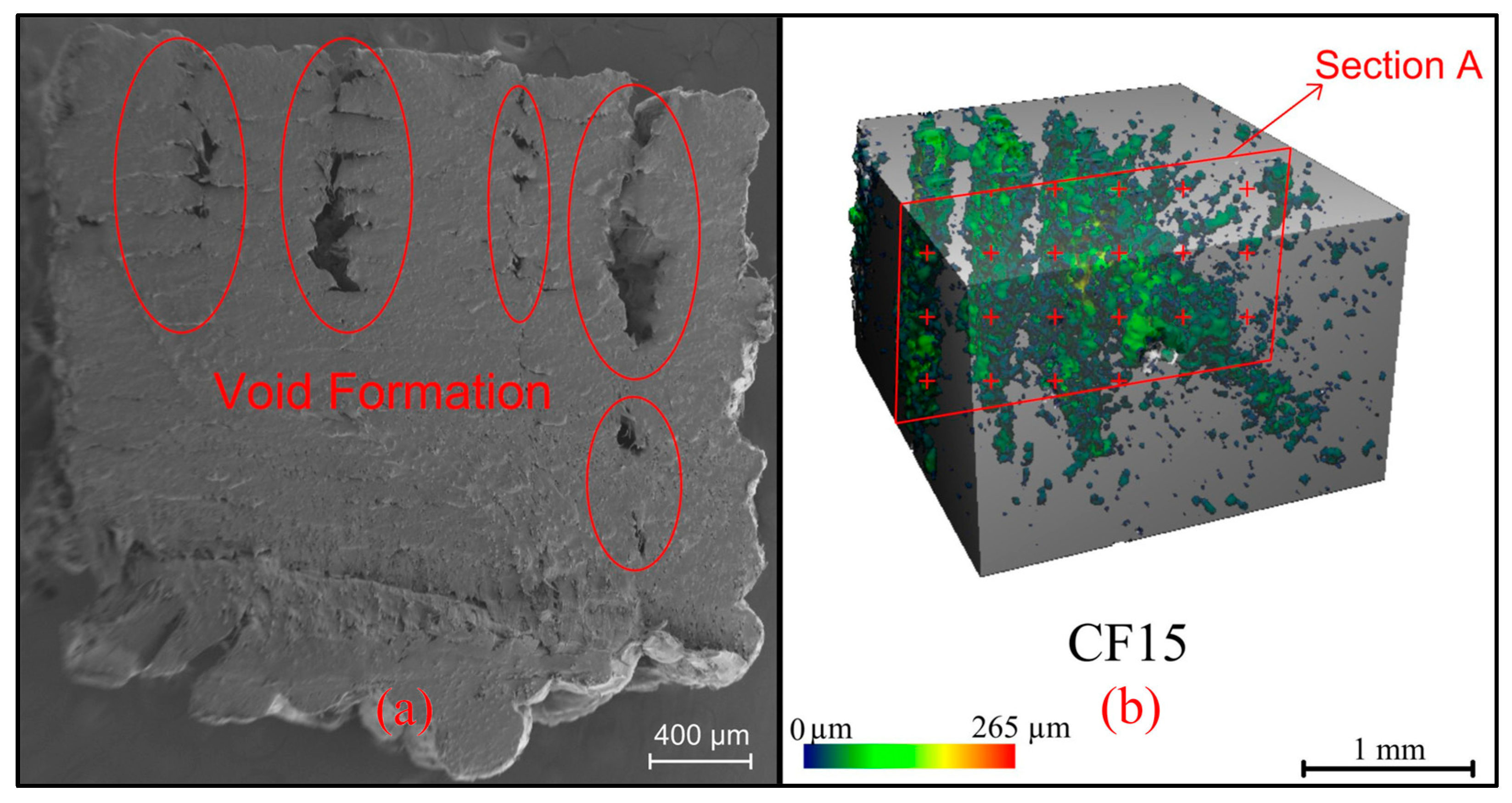
3.2. Results Obtained from Image Analysis

As shown in Figure 6, the void ratio in the sample volume is 7%, which negatively affects its mechanical properties. This result shows that the printing parameters need to be optimized. Ironing is a new pioneering method that eliminates void formation [48]. On the other hand, the SEM images show that the composite has a rough surface, which causes friction and limits the propeller’s thrust performance.
From the SEM image in Figure 7, the fibers are evenly distributed in the same direction, and the bonding of HDPE with carbon fibers is not fully realized. To eliminate this weak bonding to improve mechanical performance, it may be recommended to modify or coat with the surface of carbon fibers with some nano-additives

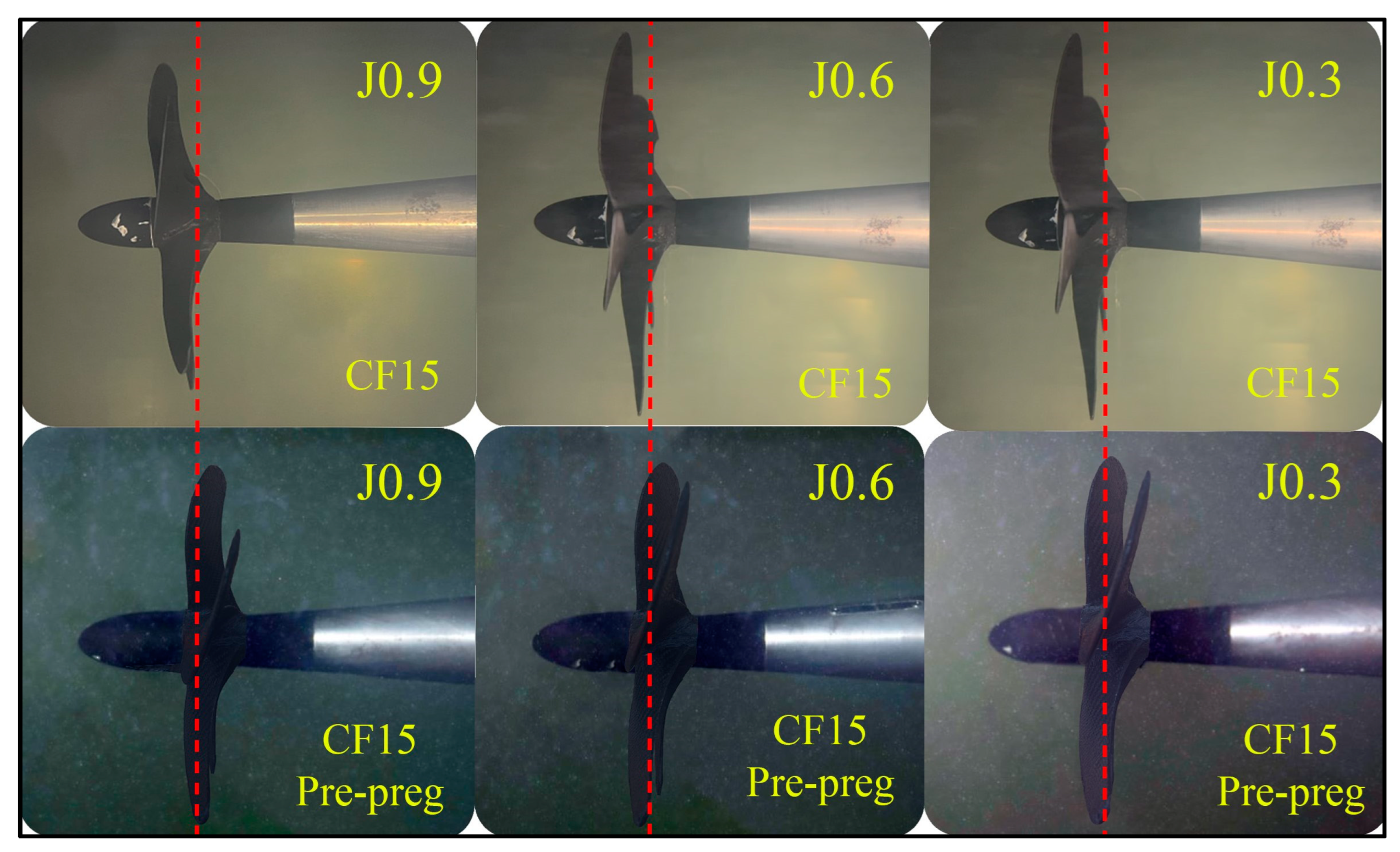
3.3. Tunnel Test Results

Figure 8 and Table 6 indicate the structural responses of the propellers during the open-water tests at a range of advance coefficients (J) from 0.3 to 0.9. The vertical red line passing through the tips of the propeller blades indicates the initial position of the blades. No significant deflection occurs in the propeller at high advance ratios (J > 0.7). The deflection becomes larger under heavy load conditions (J = 0.3).

4. Conclusions

While HDPE-based composites are becoming more widespread day by day, improving their mechanical properties and using them in a way that brings sustainability to the forefront in every branch of industry is the subject of current research. In this study, the effect of coating one of the HDPE-based composites reinforced with short fibers with a 15% carbon content (CF15), which has shown good mechanical performance in previous studies, was studied. It is thought that coating will reduce the flexibility of final products made with HDPE-based composites, depending on the place of use. The major achievements in the study can be summarized as follows:
  • The prepreg coating enabled the flexibility of the HDPE-based composite to be reduced dramatically, and thus the performance of propellers produced from this polymer composite improved by reducing the deformation at the wing tips.
  • This study, which shows that it is possible to produce and improve production with the above-mentioned composite materials to lighten the propeller, which has the most complex geometry among ship elements, has the potential to produce benefits for the relevant industry.
  • It has been seen that propellers, the most complex ship elements in terms of geometry, can be produced faster and more cost-effectively without the need for molding. Thus, it has been shown that the use of additive manufacturing in the marine industry can become widespread with pioneering applications such as the one in this study.
  • The resulting product is also 60% lighter than its metal counterparts. This lightness will not only reduce material and labor costs and time in the production phase but will also enable the ship, which will carry a lighter propeller, to be economical throughout its operating life. The prepreg coating, a practical solution proposed in this research to improve the high level of flexibility that is a problem with composite propellers, reduced the flexibility but highlighted issues that need to be worked on, such as the propeller surface roughness. In addition, the surface improvement of carbon fibers added to HDPE material as a reinforcer stands out as an important field of study.
Future studies on the subject are suggested below:
  • Interface development to improve the bonding of prepreg coatings with the surface they are coating;
  • Using vacuum-assisted methods for better coating quality;
  • Material and method development for surface improvement of reinforcement fibers for better bonding of components of composites to be used in additive manufacturing.

Author Contributions

Conceptualization, G.N., A.S., P.L. and E.A.; methodology, G.N. and S.T.; investigation, all; resources, E.A. and S.T.; data curation, A.S., A.D. and A.N.H.; writing—original draft preparation, G.N. and A.S.; writing—review and editing, P.L.; visualization, A.S.; project administration, E.A. and S.T.; funding acquisition, E.A. All authors have read and agreed to the published version of the manuscript.

Funding

The study was funded by the Dokuz Eylül University under the Research Universities Support Program (Grant no. FBA-2023-3025). This article was also delivered by the UK National Clean Maritime Research Hub, established on the 1 September 2023, and supported by the UK Department for Transport (DfT) and Engineering and Physical Sciences Research Council (EPSRC) (Grant no. EP/Y024605/1).

Data Availability Statement

Data are contained within the article.

Acknowledgments

The authors kindly acknowledge the support received from colleagues of the Newcastle University Marine Hydrodynamic Laboratory and the Emerson Cavitation Tunnel and also thank IBGEM (Izmir Biomedicine and Genome Center Electron Microscopy Core facility) for providing the related infrastructure and Defne Öztürk for her expertise during the SEM microscopy analysis.

Conflicts of Interest

The authors declare no conflicts of interest.

References

  1. International Maritime Organization. Initial IMO Strategy on Reduction of GHG Emissions from Ships; International Maritime Organization: London, UK, 2018. [Google Scholar]
  2. Lim, S.; Turkmen, S.; Rostami, A.B.; Prini, F.; Kurniawati, V.R.; Carchen, A.; Gibson, M.; Benson, S.; Birmingham, R.; Dow, R.S.; et al. Ship Performance-Using the Real World as a Laboratory. In Proceedings of the Full Scale Ship Performance, London, UK, 24–25 October 2018. [Google Scholar]
  3. Neşer, G. Polymer Based Composites in Marine Use: History and Future Trends. Procedia Eng. 2017, 194, 19–24. [Google Scholar] [CrossRef]
  4. Turkmen, S.; Wang, L.; Raftopoulos, S.; Li, C.; Norman, R. Analysis of the Hydrodynamic Performance of a Gate Rudder System. IOP Conf. Ser. Mater. Sci. Eng. 2023, 1288, 012059. [Google Scholar]
  5. Taub, A.I.; Luo, A.A. Advanced Lightweight Materials and Manufacturing Processes for Automotive Applications. Mater. Res. Soc. Bull. 2015, 40, 1045–1053. [Google Scholar] [CrossRef]
  6. Wang, J.; Li, Y.; Hu, G.; Yang, M. Lightweight Research in Engineering: A Review. Appl. Sci. 2019, 9, 5322. [Google Scholar] [CrossRef]
  7. Daniele, R.; Armoni, D.; Dul, S.; Alessandro, P. From Nautical Waste to Additive Manufacturing: Sustainable Recycling of High-Density Polyethylene for 3D Printing Applications. J. Compos. Sci. 2023, 7, 320. [Google Scholar] [CrossRef]
  8. Kreiger, M.A.; Mulder, M.L.; Glover, A.G.; Pearce, J.M. Life Cycle Analysis of Distributed Recycling of Post-Consumer High Density Polyethylene for 3-D Printing Filament. J. Clean. Prod. 2014, 70, 90–96. [Google Scholar] [CrossRef]
  9. Sözen, A.; Neşer, G.; Bengisu, M. Effect of the Geometry on the Structural Performance of High-Density Polyethylene Small Craft Joints. Ships Offshore Struct. 2022, 17, 1939–1946. [Google Scholar] [CrossRef]
  10. Singh, N.; Hui, D.; Singh, R.; Ahuja, I.P.S.; Feo, L.; Fraternali, F. Recycling of Plastic Solid Waste: A State of Art Review and Future Applications. Compos. B Eng. 2017, 115, 409–422. [Google Scholar] [CrossRef]
  11. Önal, M.; Neşer, G. End-of-Life Alternatives of Glass Reinforced Polyester Hulls Compared by LCA. Adv. Compos. Lett. 2018, 27, 134–141. [Google Scholar] [CrossRef]
  12. Directive 2000/53/EC on End-of-Life vehicles. Official Journal of the European Union, L 269/34. 2000. Available online: https://eur-lex.europa.eu/legal-content/EN/ALL/?uri=celex%3A32000L0053 (accessed on 8 April 2024).
  13. Directive 2002/96/EC on Waste Electric and Electronic Equipment. Official Journal of European Union, L 37/24. 2003. Available online: https://eur-lex.europa.eu/resource.html?uri=cellar:ac89e64f-a4a5-4c13-8d96-1fd1d6bcaa49.0004.02/DOC_1&format=PDF (accessed on 8 April 2024).
  14. Matthew, C.; Moran, F.; Jaiswal, A.K. A Review on European Union’s Strategy for Plastics in a Circular Economy and Its Impact on Food Safety. J. Clean. Prod. 2021, 283, 125263. [Google Scholar] [CrossRef]
  15. Allagui, S.; El Mahi, A.; Rebiere, J.L.; Beyaoui, M.; Bouguecha, A.; Haddar, M. Experimental Studies of Mechanical Behavior and Damage Mechanisms of Recycled Flax/Elium Thermoplastic Composite. Polym. Polym. Compos. 2022, 30, 09673911221090048. [Google Scholar] [CrossRef]
  16. Sam-Daliri, O.; Ghabezi, P.; Steinbach, J.; Flanagan, T.; Finnegan, W.; Mitchell, S.; Harrison, N. Experimental Study on Mechanical Properties of Material Extrusion Additive Manufactured Parts from Recycled Glass Fibre-Reinforced Polypropylene Composite. Compos. Sci. Technol. 2023, 241, 110125. [Google Scholar] [CrossRef]
  17. Fredriksson, D.W.; DeCew, J.C.; Tsukrov, I. Development of Structural Modeling Techniques for Evaluating HDPE Plastic Net Pens Used in Marine Aquaculture. Ocean Eng. 2007, 34, 2124–2137. [Google Scholar] [CrossRef]
  18. Chatkunakasem, P.; Luangjuntawong, P.; Pongwisuthiruchte, A.; Aumnate, C.; Potiyaraj, P. Tuning of HDPE Properties for 3D Printing. Key Eng. Mater. 2018, 773, 67–71. [Google Scholar] [CrossRef]
  19. Schirmeister, C.G.; Hees, T.; Licht, E.H.; Mülhaupt, R. 3D Printing of High Density Polyethylene by Fused Filament Fabrication. Addit. Manuf. 2019, 28, 152–159. [Google Scholar] [CrossRef]
  20. Rajeshwari, P.; Dey, T.K. Structural and Thermal Properties of HDPE/n-AlN Polymer Nanocomposites. J. Therm. Anal. Calorim. 2014, 118, 1513–1530. [Google Scholar] [CrossRef]
  21. Jagannathan, D.; Adarsha, H.; Ramaiah, K.; Prabhu, R.N. A Systematic Study on Mechanical Properties of CNT Reinforced HDPE Composites Developed Using 3D Printing. Iran. J. Mater. Sci. Eng. 2023, 20, 1–16. [Google Scholar] [CrossRef]
  22. Gogoi, R.; Maurya, A.K.; Manik, G. A Review on Recent Development in Carbon Fiber Reinforced Polyolefin Composites. Compos. Part C Open Access 2022, 8, 100279. [Google Scholar] [CrossRef]
  23. Kabir, S.M.F.; Mathur, K.; Seyam, A.F.M. A Critical Review on 3D Printed Continuous Fiber-Reinforced Composites: History, Mechanism, Materials and Properties. Compos. Struct. 2020, 232, 111476. [Google Scholar] [CrossRef]
  24. Mohammadizadeh, M.; Imeri, A.; Fidan, I.; Elkelany, M. 3D Printed Fiber Reinforced Polymer Composites—Structural Analysis. Compos. B Eng. 2019, 175, 107112. [Google Scholar] [CrossRef]
  25. Sanei, S.H.R.; Popescu, D. 3d-Printed Carbon Fiber Reinforced Polymer Composites: A Systematic Review. J. Compos. Sci. 2020, 4, 98. [Google Scholar] [CrossRef]
  26. Young, Y.L. Fluid-Structure Interaction Analysis of Flexible Composite Marine Propellers. J. Fluids Struct. 2008, 24, 799–818. [Google Scholar] [CrossRef]
  27. Rajappan, R.; Pugazhenthi, V. Finite Element Analysis of Aircraft Wing Using Composite Structure. Int. J. Eng. 2013, 2, 74–80. [Google Scholar]
  28. Warsi Sullivan, R.; Hwang, Y.; Rais-Rohani, M.; Lacy, T. Structural Analysis and Testing of an Ultralight Unmanned-Aerial-Vehicle Carbon-Composite Wing. J. Aircr. 2009, 46, 814–820. [Google Scholar] [CrossRef]
  29. Aung, P.W.; Tatarnikov, O.; Aung, N.L. Structural Optimization of a Light Aircraft Composite Wing. IOP Conf. Ser. Mater. Sci. Eng. 2020, 709, 044094. [Google Scholar] [CrossRef]
  30. İçten, B.M.; Sayman, O. Failure Analysis of Pin-Loaded Aluminum-Glass-Epoxy Sandwich Composite Plates. Compos. Sci. Technol. 2003, 63, 727–737. [Google Scholar] [CrossRef]
  31. Seresta, O.; Gürdal, Z.; Adams, D.B.; Watson, L.T. Optimal Design of Composite Wing Structures with Blended Laminates. Compos. B Eng. 2007, 38, 469–480. [Google Scholar] [CrossRef]
  32. Aktay, L.; Johnson, A.F.; Holzapfel, M. Prediction of Impact Damage on Sandwich Composite Panels. Comput. Mater. Sci. 2005, 32, 252–260. [Google Scholar] [CrossRef]
  33. Date, S.; Abe, Y.; Okabe, T. Effects of Fiber Properties on Aerodynamic Performance and Structural Sizing of Composite Aircraft Wings. Aerosp. Sci. Technol. 2022, 124, 107565. [Google Scholar] [CrossRef]
  34. George, J.; Sreekala, M.S.; Thomas, S.; George, J.; Sreekala, M.S.; Thomas, S. A Review on Interface Modification and Characterization of Natural Fiber Reinforced Plastic Composites. Polym. Eng. Sci. 2001, 41, 1471–1485. [Google Scholar] [CrossRef]
  35. Kim, J.H.; Ahn, B.K.; Ruy, W.S.; Do Kim, G.; Lee, C.S. Fluid-Structure Interaction Analysis of Flexible Composite Propellers. In Lecture Notes in Civil Engineering; Springer Science and Business Media Deutschland GmbH: Singapore, 2021; Volume 63, pp. 519–538. [Google Scholar]
  36. Rajadurai, M.; Vinayagam, P.; Priya, G.M.; Balakrishnan, K. Optimization of Ply Orientation of Different Composite Materials for Aircraft Wing. Int. J. Adv. Eng. Res. Sci. 2017, 4, 111–117. [Google Scholar] [CrossRef]
  37. Herath, M.T.; Phillips, A.W.; St John, N.; Brandner, P.; Pearce, B.; Prusty, G. Hydrodynamic Response of a Passive Shape-Adaptive Composite Hydrofoil. Mar. Struct. 2021, 80, 103084. [Google Scholar] [CrossRef]
  38. Huang, S.H.; Liu, P.; Mokasdar, A.; Hou, L. Additive Manufacturing and Its Societal Impact: A Literature Review. Int. J. Adv. Manuf. Technol. 2013, 67, 1191–1203. [Google Scholar] [CrossRef]
  39. Shen, W.U.; Mingtai, S. Analysis of the Particularity of Model Test for Composite Marine Propellers. Chin. J. Ship Res. 2021, 16, 9–14. [Google Scholar] [CrossRef]
  40. Hu, C.; Liao, X.; Qin, Q.H.; Wang, G. The Fabrication and Characterization of High Density Polyethylene Composites Reinforced by Carbon Nanotube Coated Carbon Fibers. Compos. Part. A Appl. Sci. Manuf. 2019, 121, 149–156. [Google Scholar] [CrossRef]
  41. Olesik, P.; Godzierz, M.; Kozioł, M.; Jała, J.; Szeluga, U.; Myalski, J. Structure and Mechanical Properties of High-Density Polyethylene Composites Reinforced with Glassy Carbon. Materials 2021, 14, 4024. [Google Scholar] [CrossRef]
  42. Kordsa AX-201XL, Composite Technologies Technical Data Sheet. 2022. Available online: https://composite.kordsa.com/en/images/pdf/AX201XL_Slittape_Global_TDS.pdf (accessed on 8 April 2024).
  43. ASTM D638; Standard Test Method for Tensile Properties of Plastics. ASTM International: West Conshohocken, PA, USA, 2022.
  44. ASTM D732; Standard Test Method for Shear Strength of Plastics by Punch Tool. ASTM International: West Conshohocken, PA, USA, 2017.
  45. ASTM D3410; Standard Test Method for Compressive Properties of Polymer Matrix Composite Materials with Unsupported Gage Section by Shear Loading. ASTM International: West Conshohocken, PA, USA, 2016.
  46. Atlar, M.; Sasaki, N.; Sampson, R. Propeller Ice Interaction-Effect of Blockage Proximity. In Proceedings of the First International Symposium on Marine Propulsors, Trondheim, Norway, 22–24 June 2009. [Google Scholar]
  47. Resistance Committee. ITTC-Recommended Procedures and Guidelines Testing and Data Analysis Resistance Test. In 25th ITTC, ITTC Recommended Procedures and Guidelines; ITTC: Zürich, Switzerland, 2008. [Google Scholar]
  48. Stano, G.; Sayah, N.; Smith, D.E.; Fleck, T.J. Effect of Process Parameters in Additively Manufactured Sensors Prepared via Material Extrusion Processes: Correlation among Electrical, Mechanical and Microstructure Properties. Addit. Manuf. Lett. 2024, 9, 100194. [Google Scholar] [CrossRef]
Figure 1. (a) Prepreg-coated and (b) uncoated propeller manufactured in the study.
Polymers 16 01257 g001
Figure 2. The stages of prepreg coatings of propeller blades.
Polymers 16 01257 g002
Figure 3. Curing process of the prepreg coating.
Polymers 16 01257 g003
Figure 4. Mechanical test samples of the prepreg-composite-coated samples and the axes used.
Polymers 16 01257 g004
Figure 5. Schematic of the Emerson Cavitation Tunnel [46].
Polymers 16 01257 g005
Figure 6. (a) SEM and (b) micro-CT images of CF15.
Polymers 16 01257 g006
Figure 7. (a) The CF15 composite’s SEM image showing the weak bonding of HDPE and short carbon fibers as seen in red box. (b) Homogeneous fiber distribution on CF15 composite.
Polymers 16 01257 g007
Figure 8. Deflections of propeller blades under various loads. Red dashed reference lines indicates first position of propeller tip.
Polymers 16 01257 g008
Table 1. Mechanical properties of coating prepreg composite [42].
Test PerformedPropertyTW245
Tensile 0° Tensile Stress, Mpa863
Poisson’s Ratio0.03
Modulus, Gpa58.5
Compression 0° Compressive Stress, MPa521.8
Chord Modulus, Gpa53.8
3-Point BendingFlexural Strength, Mpa854
Chord Modulus, Gpa50.9
DMAE′ (°C)113.2
Tan (δ)127.6
E″ (°C)124.5
Table 2. Main particulars of the propeller.
Propeller TypeFixed-Pitch Propeller
Propeller diameter (D), m0.2571
Pitch-to-diameter ratio (P/D) at 0.7R0.83
EAR0.466
Number of blades5
Rake angle
Skew angle (back)14.62°
Direction of rotationRight-handed turning
Hub-dia.-to-propeller dia. ratio0.18
Blade thickness at 0.75R, m0.003
Blade loading distribution (radially)Wake-adapted
Thickness distributionModified after 0.8R to tip
Table 3. Main particulars of the Emerson Cavitation Tunnel.
Description of FacilityVertical Plane, Closed Circulation
Test section size (L′B′H) (m)3.10′1.26′0.80
Test section area (m2)1.008
Contraction ratio4.271
Main pump power (kW)300
Main pump rotation speed (RPM)294
Impeller diameter (m)1.295
Maximum velocity (m/s)8
Absolute pressure range (kN/m2)7.6 (min)–106 (max)
Cavitation number range0.5 (min)–23 (max)
Model propeller size (mm)150–400
Table 4. Test conditions.
V (m/s)RPMrpsJ
3.70 957.60 159.600.9
3.29 957.79 159.630.8
2.88 957.67 159.610.7
2.47 957.72 159.620.6
1.65 957.87 159.640.4
1.23 957.69 159.610.3
Table 5. Mechanical properties of the propellers.
PropertyCF15CF15-Prepreg
Longitudinal Young’s modulus (E11) (MPa)312514,258
Transversal Young’s modulus (E22) (MPa)312514,258
Longitudinal Shear modulus (G12) (MPa)200280
Transverse Shear modulus (G13) (MPa)200280
Longitudinal Poisson ratio (ν12)0.440.26
Transverse Poisson ratio (v23)0.440.26
Ultimate longitudinal tensile strength (Mpa)24.4244.47
Ultimate longitudinal compressive strength (Mpa)18.5630.35
Ultimate transverse tensile strength (Mpa)24.4244.47
Ultimate transverse compressive strength (Mpa)18.5630.35
Ultimate in-plane shear strength (S12) (Mpa)11.5613.67
Shear strength (S13) (MPa)11.5613.67
Table 6. Total deflection (mm) on propeller tips.
CF15CF15-Prepreg
J = 0.388.9720.09
J = 0.3582.5618.,62
J = 0.476.2817.18
J = 0.653.0511.81
J = 0.741.350.91
J = 0.830.570.66
J = 0.917.550.36
Disclaimer/Publisher’s Note: The statements, opinions and data contained in all publications are solely those of the individual author(s) and contributor(s) and not of MDPI and/or the editor(s). MDPI and/or the editor(s) disclaim responsibility for any injury to people or property resulting from any ideas, methods, instructions or products referred to in the content.

