
Influence of Austenite Grain Size on the Variant Configurations of Martensite in a Fe-30.5Ni-0.155C Alloy
4MAT, Ecole Polytechnique de Bruxelles, Université Libre de Bruxelles, 1050 Brussels, Belgium
*
Author to whom correspondence should be addressed.
Crystals 2024, 14(5), 461; https://doi.org/10.3390/cryst14050461
Submission received: 12 April 2024
/
Revised: 3 May 2024
/
Accepted: 6 May 2024
/
Published: 14 May 2024
(This article belongs to the Section Crystalline Metals and Alloys)
Abstract
:A Fe-30.5wt%Ni-0.155wt%C alloy was annealed at two different temperatures to produce two different austenite grain sizes. In the coarse-grained specimen, hierarchical configurations of variants are formed and carefully analyzed using EBSD. These typical patterns result from the alternate formation of two perpendicular plate groups of variants over several length scales, and two distinct types of mechanical couplings are shown to occur sequentially in the process of the transformation of an austenitic grain. In the fine-grained specimen, the martensite start temperature is depressed below liquid nitrogen temperature, and the martensitic transformation can only occur under stress assistance. Grain size reduction brings about a dramatic change in the morphology of martensite and its configurations. Martensite is fully twinned, and martensite variants arrange themselves into self-accommodating configurations involving all four variants of the same plate group. Those specific configurations share striking similarities with those usually encountered in conventional shape memory alloys. The reversion of such microstructures upon heating is believed to be at the origin of the observed shape memory effect.
1. Introduction
1.1. Variant Pairings in Steel Martensite
The martensitic transformation in steels is a displacive phase transformation that involves a deformation of the parent phase. There are 24 a priori equivalent orientations for the product phase, but it has long been recognized that specific pairings between martensitic variants are systematically observed. In steels, martensite can adopt two different morphologies, lath or plate. Specific variant pairings are associated with each morphology. Lath martensite adopts hierarchical configurations of variants consisting of packets, blocks, and sub-blocks [1,2,3]. This arrangement leads to the preferential selection of particular variant pairings among the 16 possible operators that act between variants of the Kurdjumov–Sachs (KS) orientation relationship (OR) [4]. In lath martensite, the dominant pairings are between variants that belong to the same packet [2,5,6]. A packet contains six variants that share the same plane in the austenite. There are five distinct pairings that can occur between variants of the same packet. Among them, those involving the smallest misorientation angle, which corresponds to the pair in the classification of Morito et al. [2], dominate over the others at low carbon content, i.e., at relatively high transformation temperature. The two variants involved in this pairing share the same compression axis of the Bain strain. Kinney et al. claimed that this low-angle pairing is a crucial feature of lath martensite formation [1]. The authors state that the bivariant block structure, which is linked to this pairing, enables blocks to be stacked in an essentially stress-free pattern [7]. It has been reported that as the carbon content increases and as the transformation temperature decreases, there is a shift in the dominance of variant pairing from the low angle to the twin-related variant pair [5,6]. A well-known morphological transition occurs in carbon steels at approximately 0.8wt%C and in Fe-high Ni alloys at around 30wt%Ni [6,8]. Below this threshold value, lath martensite is obtained, while at higher carbon (or Nickel) content, the morphology becomes essentially plate-like. Two plate-like morphologies can be further distinguished depending on the transformation temperature (Ms). When Ms is below room temperature but above 150 K, martensite takes on a lenticular morphology with curved interfaces with the austenite. If Ms is below approximately 150 K, the martensite transforms into thin plates and shares straight interfaces with the austenite. Concomitant with the morphological transition from lath to lenticular/thin plate, a change in the variant configurations as well as in the associated pairing tendency is observed. The dominant pairings observed in lenticular and thin plate martensite are between variants belonging to the same plate group [6,9,10,11]. Each plate group consists of four variants whose habit planes gather around a common plane in the austenite. The couplings are referred to as the Spear, Wedge, and Kink couplings, corresponding to , , and pairs in Morito et al.’s classification. Shionoara et al. demonstrated that these couplings are favored because they have the smallest degree of incompatibility at their junction plane (JP) [10,12].
1.2. Effect of Grain Size on Ms, Martensite Morphology, and Its Kinetics
The Ms temperature is determined by the grain size of the austenite, assuming no change in the chemical composition [13]. A decrease in austenite grain size results in a decrease in Ms. This is believed to be due to the constrained propagation of the seminal plate, which increases the driving force required to initiate the transformation [14,15]. Umemoto et al. have thoroughly studied the effect of grain size on Ms in Fe-High Ni alloys [16]. The authors have shown that Ms is globally independent of grain size for grain sizes above approximately 150 µm in Fe-31wt%Ni-0.28wt%C. However, it decreases steeply with a decrease in grain size below 150 µm. The authors also claimed that a morphological transition of martensite from lenticular to thin plate is associated with a refinement of the austenite grain size below about 50 µm in Fe-31Ni-0.28C (wt%). Interestingly, the morphological transition has been shown to be associated with a change in the transformation kinetics. In the coarse-grained samples, the martensitic transformation begins at a specific temperature (called Mb), and a high-volume fraction is transformed suddenly in a single burst once this critical temperature is reached. Up to 70% of martensite can form at once, leading to a sudden release of latent heat of transformation that can cause a temperature rise of up to approximately 30 °C [17]. Skrotzki [18] monitored the latent heat release as a function of undercooling in Fe-30.25Ni using differential scanning calorimetry. These measurements have revealed three successive peaks of heat flow at different temperatures, indicating that the transformation occurs in three sequential steps. The author has related the stepwise kinetics to the microstructure of the transformed specimen, which consists of a hierarchical microstructure made up of interpenetrating zig-zag patterns. Figure 1 shows an optical micrograph of this kind of microstructure obtained by the present authors in a Fe-30.5Ni-0.155C alloy [19]. Three interpenetrating zig-zag patterns of different characteristic length scales can be distinguished, numbered from 1 (largest length scale) to 3 (smallest length scale). Variants that share a common length scale and, therefore, belong to the same zig-zag pattern are said to pertain to the same generation of variants.
When a zig-zag pattern forms, the austenite is partitioned into triangular islands that decrease in size at each generation. Some of these austenite pockets are filled by a smaller zig-zag pattern with habit planes perpendicular to those of the variants of the previous generation. This microstructure was analyzed in relation to the DSC measurements conducted by Strotzki [18]. According to the author, each generation would form at a distinct temperature, indicating that the material would have several Mb’s. The link between kinetics and microstructure can be further explored by considering the crystallography and the variant pairings associated with this type of transformation. It is widely accepted that the zig-zag arrangement occurs due to self-accommodating mechanical couplings between variants with approximately parallel habit planes. The shape deformation of the first variant is partially compensated for by the formation of a second variant whose shape deformation goes in an essentially opposite direction [9,11]. As the accommodation is not perfect, the second variant is further compensated for by the formation of a third variant (crystallographically equivalent to the first), and so on. This phenomenon is believed to be driven by the need to reduce the net transformation strains in the sample. This mechanism satisfactorily explains the formation of a zig-zag pattern within one generation, but it fails to explain the transfer of the transformation from one generation to the next. The habit planes of the variants pertaining to successive generations are perpendicular, suggesting that their mechanical coupling is essentially different from that at play in the formation of a zig-zag pattern. The kinetics of the thin plate transformation are markedly different from that of lenticular martensite. The burst reaction is suppressed, or at least significantly reduced, in the case of the transformation to thin plate martensite [16,20]. The crystallography of the transformation product does not reflect the difference in kinetics between lenticular and thin plate martensite, as both exhibit similar variant pairing tendencies [10,11,12]. Therefore, a comparative analysis of the respective variant configurations adopted by lenticular and thin plate martensite is necessary to better understand the origins of the difference in their transformation kinetics.
1.3. Aims of the Present Study
The aim of this contribution is to compare the crystallography of the variant configurations of lenticular and thin plate martensite formed in a Fe-30.5wt%Ni-0.155wt%C alloy. To achieve this, a thermo-mechanical process was designed to obtain two different austenite grain sizes. The first grain size, referred to as the coarse grain size, is around 500 µm. Under such conditions, the Ms of this alloy (around 220 K) is approximately independent of grain size, and the resulting transformation product takes on a lenticular shape. This specimen was used to study the crystallography of the hierarchical microstructures of martensite resulting from the burst transformation. The mechanical couplings observed between the variants in this prototypical pattern were studied to gain new insights into the sequential nature of the transformation. The second grain size, referred to as the fine grain size, was selected to correspond to the size of the remaining pockets of austenite in the coarse-grained specimen that undergoes a burst-type transformation. By design, this grain size is stable at liquid nitrogen temperature but can be transformed with the assistance of an external stress. This study employs a fine grain size to evaluate the morphological transition from lenticular to thin plate, as claimed by Umemoto et al. [16], and its impact on variant configurations.
2. Materials and Methods
A Fe-30.5wt%Ni-0.155wt%C alloy was used in the present study. The average grain size of the as-received material is around 50 µm, and its Ms is around 220 K. To create hierarchical configurations of variants, the as-received material was annealed at 1373 K for 15 min, resulting in an average grain size of approximately 500 µm. This sample is referred to as the coarse-grained (CG) sample throughout the study. The Ms of this specimen remains close to 220 K. The fine-grained sample was produced by cold rolling (ε = 1) and annealing at 823 K for 15 min. The resulting average grain size is approximately 7 µm, and the Ms temperature is below the temperature of liquid nitrogen. This sample will be referred to as the fine-grained (FG) sample in this study. The FG sample underwent transformation under uniaxial tensile stress at a fixed stress of 300 MPa, equivalent to the sample’s yield strength at room temperature. The tensile specimen was placed in a waterproof container before being fitted into the tensile machine (Lloyd LR-30 K). Liquid nitrogen was then poured into the plastic container after the load was applied to induce the transformation. At the end of the load drop characteristic of the transformation, the load was removed. Specimens were conventionally prepared for optical microscopy. Their microstructures were revealed by etching in 4% NITAL followed by color etching for a few minutes in a solution of 20% Sodium Meta-Bisulfite + water. Samples for EBSD analysis were electropolished after mechanical polishing in a mixture of 90% acetic acid + 10% perchloric acid at 20 V. EBSD measurements were conducted on a Hitachi SU70 FEG-SEM operated at 15 kV equipped with an EDAX Hikari EBSD camera. The crystallographic analysis was performed using TSL OIM software v7.4. The crystallographic predictions of the Bowles and Mackenzie theory for the crystallography of martensite were calculated using PTClab software v1.v18.9 [21] with the following lattice parameters determined by X-ray diffraction: and . The predicted habit plane, which is calculated to be , will be approximated as in the following in order to allow direct comparison with the results obtained in other studies. The present study employs Morito et al.’s variant classification, occasionally supplemented by Okamoto’s [3,11]. This classification can be found in Supplementary Material Table S1.
3. Results
3.1. The Crystallography of Plate Groups
The 24 transformation variants can be classified into six plate groups (PG) based on their habit planes, which are almost parallel to each other and gather around a common plane of the austenite. Okamoto’s classification [11] attributes a number, from 1 to 6, to each group. Each variant in the same PG is assigned a capital letter, from A to D. The variants belonging to the same PG come from two different Bain correspondences. The variants that belong to the same PG and share the same Bain correspondence (e.g., / and / pairs in PG1) are related through a low angle misorientation of 15.23° about an axis that can be approximated as . According to Okamoto, this variant pairing adopts a Kink morphology. The pairings between variants belonging to the same PG but originating from two distinct Bain correspondences can be of two types. / and / pairs are related through a rotation of 56.65° about a axis and adopt a Wedge morphology. On the other hand, the / and / pairs are related through a rotation of 51.38° about a axis and adopt a Spear morphology. Figure 2 summarizes the possible pairings between the variants of the same plate group.
3.2. The Hierarchical Configurations of Variants in CG Sample
3.2.1. Crystallographic Analysis
Figure 3a shows an EBSD Image Quality (IQ) map of two successive generations of variants formed in the CG sample. This area captures the essential crystallographic features of the hierarchical configurations of variants that are typical of the burst transformation of lenticular martensite. All of these martensite variants originate from the same austenitic grain, whose average orientation can be determined using the EBSD data of residual austenite (highlighted in orange in Figure 3a). Figure 3c shows the (green stars) and the (black dots) pole figures of residual austenite. By using the average orientation of austenite and the orientation relationship calculated from the PTMC, each martensite grain can be linked to a unique transformation variant listed from 1 to 24. Figure 3b shows the corresponding reconstructed variant map. The first generation consists of variants and , which have habit planes clustering around the plane of austenite and belong to PG5. These variants form a Wedge pairing and enclose the variants of the second-generation , , , and . The habit planes of these four variants, which belong to PG6, cluster around the plane of austenite. These two plate groups, PG5 and PG6, are considered perpendicular because their respective planes are orthogonal. Figure 3a shows that the Wedge coupling dominates (46.7% of the total boundary length) over the Spear coupling (16.2%). The Kink coupling has the shortest length fraction (only 4%). Shinohara et al. reported that the Spear and the Wedge couplings are found in a similar proportion between variants of lenticular martensite [10]. However, the study did not specifically examine the hierarchical configurations of variants, such as those shown in Figure 1 and Figure 3. This suggests that the predominance of the Wedge pairing among the variants of the same generation is a characteristic feature of the hierarchical microstructures typical of burst transformation of lenticular martensite. The origins of the preferential pairings are discussed in the next section within the framework of the mechanical couplings between variants.
3.2.2. Mechanical Couplings between Variants
The shape strain associated with the formation of each variant can be calculated using the phenomenological theory. For each couple of variants A and B, the difference between their shape strains and can be calculated by the normalized scalar product [22]:
This coupling factor varies from +1 when the two shape strains are exactly the same to −1 when the two shape strains are exactly opposite. When the coupling factor is positive, the formation of the first variant triggers the formation of the second variant, and their shape strains cumulate. Therefore, the reaction is autocatalytic in essence. Conversely, when the coupling factor is negative, the shape deformation of the second variant screens the shape deformation of the first, tending to cancel it out. Thus, the reaction is a self-accommodation. All possible couples of the variants of Figure 3a have been considered. The coupling factor for each of the considered couples has been calculated and is reported in Table 1. The solution type for the rank-1 connection between the two variants is given, with reference to the work of Shinoara et al. [10]. Additionally, the angle between their respective habit planes and the misorientation angle/axis are also reported. Two types of couplings can be distinguished. The couplings between variants of the same generation and between successive generations are referred to as inter-generational and intra-generational couplings, respectively.
The variants of the same generation belong to the same plate group, and three distinct couplings can occur between them. The dominant coupling between the variants of the first generation and between the variants of the second generation is the Wedge coupling. This coupling occurs between variants whose habit planes are almost parallel (15°), and its coupling factor is highly negative (−0.85), making this variant pairing self-accommodating. The estimated incompatibility at the junction plane for this Type II solution, as determined by the angular deviation from the invariant plane condition, is very low at 0.6° for this variant pairing. This suggests that this interface can form without introducing significant distortion [10]. The Spear coupling is the second most common coupling and occurs between variants whose habit planes are relatively close to each other, at 26°. This variant pairing is self-accommodating, with a coupling factor of −0.88. Additionally, its incompatibility at the junction plane is even lower than that of the wedge coupling, at almost 0°. The Kink coupling, which is less frequently observed, has a high positive coupling factor of +0.88. It is the only possible autocatalytic coupling between variants of the same plate group. The dominance of self-accommodation between variants of the same generation, forming a zig-zag configuration, is evidenced by the reduced presence of the Kink coupling. The less frequent observation of this coupling may be explained by its higher incompatibility at the junction plane (around 5°) compared to the two other highly compatible, self-accommodating couplings. An important consequence of the formation of zig-zag configurations of variants is that the size of the austenite pockets left untransformed decreases at each generation. The residual austenite island’s characteristic length scale is approximately divided by a factor of four at each generation, as seen in Figure 1. Therefore, it is crucial to understand the mechanism responsible for transferring the transformation process from one generation to the next. Three distinct couplings between variants belonging to two successive generations should be considered, as presented in Table 1. Two of them are auto-catalytic, corresponding to relatively low misorientation angles of 12.6° and 19.3°. The third coupling is self-accommodating and corresponds to a high misorientation angle of 53.1°. It is important to note that the inter-variant boundary length fractions for these three possible couplings are essentially similar and small due to the reduced contact area between perpendicular variants. Therefore, it is not possible to assess the preferred perpendicular coupling based solely on the measurement of this length fraction. Similarly, the degree of incompatibility at the junction plane cannot be used to explain the preferential formation of a particular type of pairing. The initial hypothesis of our analysis is that not all variant pairings observed between two successive generations of variants are the results of the impingement between the plates. It is believed that a specific pairing exists between variants belonging to successive generations that enables the transfer of the transformation. This is supported by the following detailed crystallographic analysis. Figure 4 shows a composite EBSD map. Variant of the first generation is colored based on the deviation angle from the grain reference orientation. The average orientation of grain is calculated, and each pixel of is shaded according to its misorientation angle relative to this average. Figure 4 also shows the IPF map of variants of the second generation. Large orientation gradients, as indicated by the red arrows in Figure 4, are observed inside , near to its interfaces with the variants of the second generation. The inset of Figure 4 shows a misorientation profile along the black dotted line that starts from the midrib of and ends inside variant . The orientation change from to is gradual, with a maximum point-to-point misorientation angle of about 4°. This is distinct from all the other pairings, where the orientation change at the interface between the two variants is abrupt, and the point-to-point misorientation profile exhibits a peak of misorientation equal to the misorientation angle of the variant pairing when crossing the interface. Such a misorientation profile is given for the interface between variants and of the second generation in the Supplementary Material Figure S1. The data presented in Figure 4 indicates a gradual orientation change, suggesting that variant originated from variant . This hypothesis is supported by the coupling factor between these two variants, which is almost equal to one, indicating that their shape strains are roughly identical (see Table 1). It is therefore suggested that forms through the branching of variant .
It is hypothesized that the growth of the side plate initiates the transformation at a smaller length scale. The auto-catalytic coupling / associated with the low misorientation of 12.6° around is believed to be responsible for this initiation. Once the first variant is formed, the transformation spreads through self-accommodation, resulting in the formation of a new zig-zag pattern. This sequence, consisting of zig-zag growth followed by branching, is thought to occur multiple times until the size of the austenite pockets becomes too small for the transformation to take place. The following section of the study concentrates on the configurations of variants that can be achieved in small grains of austenite when the transformation is induced by an external stress.
3.3. Self-Accommodating Configurations of Variants in FG Sample
The average grain size of the FG sample is around 7 µm. An EBSD IPF map of the initial microstructure of the FG sample and its grain size distribution are given in the Supplementary Material Figure S2. A SEM micrograph of the FG sample transformed under stress is shown in Figure 5. The martensite plates are fully twinned and arranged into a lamellar structure, which is different from the zig-zag patterns observed in the coarse-grained sample (see Figure 1 and Figure 2). The transformation is not complete, and some islands of residual austenite are visible in Figure 5. Only a single generation of variants per austenite grain is observed. The length fraction of the martensite/martensite interfaces is much larger than that of the austenite/martensite interfaces. The configuration is dominated by the influence of these junctions. Therefore, it is necessary to investigate their crystallographic nature further.
The crystallography of martensite in the fine-grained specimen was investigated using EBSD. A SEM micrograph in Figure 6a shows a typical configuration of variants formed in the FG sample, consisting of interconnected twinned domains, similar to Figure 5. Variant identification was performed using the orientation of the residual austenite (γ in Figure 6). Figure 6b shows the variant map of Figure 6a. The four possible variants pertaining to PG2 are formed in the example of Figure 6b. Figure 6c is the pole figure of the theoretical habit planes (HP) of the variants of PG2. These HPs gather around the common plane in the austenite. It has been verified that many other grains in this sample also transform into the four possible variants of only one plate group. As is commonly understood, the average shape strain of the four variants in the same plate group is nearly zero, resulting in a self-accommodating plate group configuration [11,23].
All three possible junctions between variants of the same plate group are formed in the example of Figure 6. The junction planes can be calculated theoretically using the algorithm described in [24,25]. Table 2 presents the predicted JPs for the three interfaces depicted in Figure 6a, along with their respective deviation in degree from the invariant plane condition.
The JPs of the Spear and Kink couplings have rational indices, while that of the Wedge is irrational. Figure 6a shows the theoretical traces of the JPs plotted against the corresponding experimental boundaries, which closely match. The configuration observed in Figure 6 is an assemblage of two basic clusters of variants. The first cluster is a composite-spear (CS) cluster. Shinohara et al. studied this cluster in lens martensite and found that the cumulative rotation around the JPs of such a cluster is equal to 0° [10]. The formation of this cluster is favored as it minimizes the cumulative degree of incompatibility at the JPs. A quite unusual cluster is commonly found in the FG sample. This cluster is a triple junction that involves all three possible junction planes between variants of the same PG. Figure 7a shows a SEM micrograph of such a cluster.
Figure 7b shows the EBSD variant map of a similar cluster formed in the austenite grain of Figure 6. To the authors’ knowledge, this cluster has not been previously reported in the literature. The cumulative degree of incompatibility at the JPs for this cluster can be evaluated by calculating the cumulative rotation, , at the JPs:
is a rotation of 4.94° around an axis close to . The formation of this cluster is a priori unfavorable in terms of the cumulative degree of incompatibility at the JPs and would not be expected to form experimentally. The theoretical deviation from the invariant plane condition at the Kink junction is much higher than for the other two types of junctions (refer to Table 2). is therefore expected to be dominated by the large degree of incompatibility of the Kink junction. To estimate the experimental incompatibility at the Kink junction, it is necessary to convert the martensite orientations obtained by EBSD back into the parent austenite reference frame. This can be achieved using the method described in [12]. Next, the misorientation between each reverted martensite pixel and the reference austenite orientation is calculated. Figure 8a,b show the maps for the angle and the axis of this misorientation for the case of the Kink junction / in Figure 7b, respectively.
Figure 8a illustrates that the deviation angle from the invariant plane condition is one-sided and confined to the side of the junction. The maximum angle of the deviation is approximately 3.5° (see white arrow in Figure 8). This value is smaller than the theoretical value of approximately 5° (see Table 2). Figure 8b shows the corresponding deviation axis map. This axis is close to in the region of maximum deviation angle. This deviation from the expected direction is significant. Therefore, the degree of incompatibility at the kink junction is lower, and its axis is substantially different from that predicted by theory. It is also lower than in the thin plate martensite formed in a coarse-grained sample, for which Shinoara et al. found a deviation very close to the experimental predictions [12]. The fundamental reasons for this discrepancy remain unclear at present. However, it is believed that the lower degree of incompatibility at the Kink junction is a key factor in the formation of self-accommodating configurations in the FG sample.
4. Discussion
The size of the austenite grain has a significant influence on both the morphology and the configurations of martensite in the Fe-Ni-C alloy. In the CG specimen, variants form a hierarchical configuration across multiple length scales, while in the FG specimen, a single plate group of variants with the same characteristic length scale is observed. Notably, only a few variant pairings are required to explain the formation of both configurations. For the hierarchical configuration, this pattern consists of only two perpendicular plate groups formed alternately, resulting in a total of eight variants. Variants of the same generation belong to the same plate group. The crystallographic analysis presented in Figure 2 shows that only self-accommodating couplings are observed between the variants of the same generation. These two couplings are recognized as being associated with high angle misorientations (56.6° about an axis close to and 51.4° about an axis close to ) and are characteristic of the transformation that occurs in Fe-High Ni alloys. They involve variants that have almost parallel habit planes and whose shape strain directions go essentially in opposite ways. They are referred to as the Spear ( ) and the Wedge () couplings. The auto-catalytic Kink coupling is the third possible coupling between variants of the same plate group. However, it is much less frequently observed experimentally compared to the two other couplings. This coupling is associated with a low misorientation angle ( ) and involves variants whose shape strain is essentially the same. The lower fraction of Kink coupling is attributed to its high degree of incompatibility at the JP [10,12]. Therefore, variants of the same generation form a zig-zag pattern in an essentially self-accommodating manner. This configuration can result from a chain reaction triggered by a single nucleation (burst transformation) event at a fixed temperature [9]. In this scenario, the stress configuration associated with the formation of one variant assists the growth of the next variant. The zig-zag pattern of variants divides the transformable volume. That is, the austenite grain size decreases from one generation to the next by a factor that is directly related to the acute angle of the zig-zag pattern. This angle, in turn, is related to the self-accommodating variant pairing at play between variants of the same generation. As it is widely acknowledged that the Ms temperature decreases with austenite grain size [26,27], it is expected that additional undercooling is required to initiate the transformation in the austenite pockets that were not transformed by a generation of variants. This hypothesis is supported by the DSC measurements conducted by Skrotzki [18], which revealed three distinct peaks of heat flow during the slow cooling of a Fe-30.25%Ni alloy, each of which was attributed to the formation of a generation of variants. The number of variant generations is directly related to the initial austenite grain size and the critical grain size below which austenite is mechanically stabilized. This size is estimated to be around 10 µm in the present alloy, based on the triangular island of retained austenite in Figure 3. This estimation aligns with Guimarães’ model [28], which predicts that the stabilization of austenite should occur in the range of 5 to 15 µm in a Fe-31.9Ni-0.02C alloy. Although it is clear that undercooling is necessary to transfer the transformation process to a smaller length scale, it is also important to identify the mechanism that is activated by this undercooling. The crystallographic analysis presented in Figure 4 provides new insights, suggesting that the transformation is transferred through the formation of perpendicular side plates that nucleate from the fully-grown plates of the previous generation. Side plates, also known as branches, have been observed in and martensites [29,30,31]. However, their crystallography has not been extensively stdied. The analysis presented here reveals that the side plates are paired with the variant of the previous generation through a low angle misorientation of 12.6° around a axis. To the authors’ knowledge, the key role of this variant pairing in the process of forming the hierarchical configuration of variants has never been reported in the literature. The two variants involved in this pairing have almost perpendicular habit planes and similar shape deformation (positive coupling factor close to +1). This suggests that the side plates nucleate due to undercooling. This occurs when a given variant can no longer laterally thicken due to the stress field accumulated in the surrounding austenite. Based on the argument originally proposed by Bokros and Parker [9], it is hypothesized that the growth of a side plate is favored because perpendicular variants have a minimal portion of their surface area in the disc-shaped stress field induced by the parent, fully-grown plate. Further finite-element analysis could support this qualitative argument. Once initiated on a smaller scale, the transformation should proceed as in any other constrained environment through the self-accommodating process described previously. This will result in the formation of a new zig-zag pattern. The formation of a hierarchical configuration of variants is schematically summarized in Figure 9.
The formation of the first variant starts at Ms (Figure 9a). This variant grows quickly until it is impeded by the austenite grain boundaries. The stress concentration at the plate tips promotes the formation of new self-accommodating variants at the same temperature, which form a zig-zag pattern (Figure 9b). Additional undercooling below Ms promotes the nucleation of perpendicular side plates from the fully-grown plates of the previous generation by a branching mechanism (Figure 9c). For clarity, only one side plate (that has nucleated from the red plate) is shown in Figure 9c. There is, however, a priori no reason for the other fully-grown plate (blue plate) to induce the formation of a side plate. The side plates grow until stopped by the other fully-grown plate. The stress concentration at their tips then triggers a chain reaction, resulting in the formation of a new zig-zag pattern (Figure 9d).
Reducing the austenite grain size promotes the formation of variant configurations that involve all four variants in the same plate group and compels them to share all three possible types of junctions. The twinned-domain structures, as shown in Figure 5 and Figure 6, exhibit remarkable morphological and crystallographic similarities to those found in conventional SMAs [26,27,32]. However, in conventional SMAs, plate group configurations can form in much coarser parent grains up to the millimeter scale. In contrast, in the present case, a reduction in grain size is necessary for their development. Although the formation of self-accommodating plate group configurations is common in many SMAs, it has only been sparsely reported in the literature for Fe-Ni-C alloys. Kaletina et al. [33] reported a similar microstructure in the case of magnetic field-induced martensitic transformation in a fine-grained Fe-31Ni-0.25C alloy. However, the authors did not relate their observations to crystallographic considerations or plate group configurations.
Owing to the striking morphological as well as crystallographic similarities between the present microstructures and those encountered in conventional SMAs, the shape memory capabilities of the present alloy in its fine-grained condition were assessed using the bending test procedure described in [34]. A sample of the FG specimen, 1 mm thick, was bent to 180° in liquid nitrogen around a cylindrical piece of copper, 24 mm in diameter, to induce the transformation. The maximum tensile strain at the outer edge of the specimen was determined to be approximately 4%. The sample was returned to room temperature. It recovered some of its deformation elastically when the load was removed (see Figure 10a). It was then rapidly heated to 873 K to induce the reverse transformation. The residual strain was measured after recovery annealing to calculate the shape recovery rate (see Figure 10b).
This estimated shape recovery rate for the present alloy is around 60% (equivalent to approximately 2.4% strain recovered), which is very close to the best rate obtained by Kajiwara et al. in an ausformed Fe-31Ni-0.4C alloy [35]. Therefore, it is believed that the stress-induced martensitic transformation occurring in the fine-grained sample is partially reversible. For a large shape memory effect during the FCC to BCT transformation in ferrous alloys, three important conditions must be met [36,37,38]. Firstly, the austenite must be hard enough to prevent plastic deformation during the transformation. Secondly, the ordering of the parent phase is desired. Finally, the martensite tetragonality should be high to decrease the twin boundary energy. It appears that the first two conditions are not met in the present alloy. The reduction of austenite grain size from 250 µm to 10 µm has only a limited influence on austenite strength, as already observed by Hayzelden et al. [13]. Additionally, the hardness of austenite in the fine-grained sample (240 HV) is lower than that found in precipitation-strengthened Fe-Ni-Co-Ti alloys, which can reach values as high as 450 HV [37]. Moreover, despite the low austenitization temperature of 873 K, no ordering of the parent austenitic phase was detected in the fine-grained austenite during the TEM examinations. However, the question of the tetragonality of martensite is more complex. X-ray diffraction measurements performed at room temperature did not reveal any significant tetragonality of martensite in the fine-grained sample. This is not surprising considering the low carbon content of the present alloy (0.155wt%). However, it is still possible for martensite to have a high tetragonality at the formation temperature (i.e., 77 K). It is well known that martensite formed at low temperatures in Fe-Ni-C alloys exhibits abnormally high tetragonality that decreases upon heating to room temperature [39]. The exact origin of this abnormal tetragonality at low temperatures and its decrease upon heating to ambient is still unclear. However, it seems to be a unique feature of thin plate (internally twinned) martensite since the tetragonality of lenticular martensite is known not to evolve upon heating [39]. Therefore, it is assumed that the martensite formed in the present fine-grained austenite had a high tetragonality during its formation at low temperatures. This would be coherent with the analysis of Bhattacharya et al., who proved that a martensitic transformation can only be reversible if the symmetry groups of the parent and product phases are included in a common finite symmetry group. This condition is satisfied for an FCC to BCT transformation but not for an FCC to BCC transformation [24]. The shape memory effect observed in the present alloy indirectly proves the tetragonality of martensite at its formation temperature. Additionally, if the tetragonality of martensite decreases upon heating from the transformation temperature, the reversibility of the transformation is believed to decrease accordingly. This could explain why the shape recovery is not complete under the experimental conditions described above. However, in line with these considerations, the present alloy may exhibit improved shape memory properties around Ms. This improvement may involve the movement of twin boundaries or the re-orientation of martensite plates through the movement of martensite interfaces [40,41]. It is also believed that a better understanding of the crystallography of the unusual triple junction clusters evidenced in Figure 7 could lead to a significant improvement in the shape memory properties of the present alloy. It was shown that this specific configuration of variants is easier to form in the present alloy due to a decrease in incompatibility at the Kink junction. The maximum deviation from the invariant plane condition at this junction is approximately 3.5° (Figure 8). In contrast, Shinoara et al. reported a value of 5° (very close to the theoretical predictions) for thin plate martensite formed in coarse-grained austenite. Additional experimental studies are necessary to comprehend the reason for this difference. As mentioned above, only those Fe-Ni-C alloys that allow the formation of thin plate martensite are considered potential candidates with good shape memory properties. According to Maki et al., this corresponds to alloys with an Ms temperature below about 120 K. Nickel tends to decrease the Ms, while carbon increases the lenticular to thin plate temperature transition. Thus, in a C-free Fe-Ni alloy, this transition occurs below liquid nitrogen temperature, whereas in a Fe-Ni-C alloy containing 0.8wt%C, this transition temperature increases to about 170 K. However, these transition temperatures are always given for a coarse-grained austenite. To the best of the authors’ knowledge, for the case of Fe-Ni-C alloys, thin plate martensite has only been observed in coarse-grained austenite in the literature. The present study extends the range of possible chemical compositions to those that allow the formation of lenticular martensite in their coarse-grained state. That is, the reduction in Ms due to the reduction in austenite grain size is effective in inducing the morphological transition from lenticular to thin plate. This allows thin plate martensite and its associated shape memory properties to be obtained at a lower nickel content.
5. Conclusions
The present study demonstrates that the variant pairing tendencies of plate martensite are largely unaffected by the austenite grain size in the Fe-30.5Ni-0.155C alloy. The microstructural features observed experimentally can almost be explained totally by considering only the three possible pairings between variants of the same plate group. In the coarse-grained specimen, the hierarchical configurations of variants result from the alternate formation of perpendicular plate groups of variants. The self-accommodating pairings (Wedge and Spear couplings) dominate between variants of the same generation and the Kink pairing is almost absent. The transfer of the transformation process from one generation to the next is facilitated by the branching of primary plates. This mechanism involves a low-angle autocatalytic coupling triggered by the increasing driving force provided by undercooling. In the fine-grained specimen, each austenite grain forms a single plate group. Martensite appears fully twinned and develops twinned domain structures that share striking morphological and crystallographic similarities with those encountered in conventional shape memory alloys. The moderate recovery strain of 2.4% is believed to originate from the reversible deformation of these domains.
Supplementary Materials
The following supporting information can be downloaded at: https://www.mdpi.com/article/10.3390/cryst14050461/s1, Figure S1: (a) EBSD variant map showing the variant pair /. (b) misorientation profile along the dotted line in Figure S1a. Both the point-to-point and the point-to-origin profiles show a steep increase when crossing the junction plane; Figure S2: (a) EBSD IPF of the FG sample before transformation and (b) corresponding grain size distribution. Table S1: Variant classification used in the present study following the convention of Morito et al. The lattice invariant shear systems, as well as the habit planes, are given with reference to the austenite. Misorientation axis from are given with reference to the BCC phase. The predicted habit plane, which is calculated to be , is approximated as .
Author Contributions
Conceptualization, L.M. and S.G.; methodology, L.M.; software, L.M. and S.G.; data curation, L.M.; writing—original draft preparation, L.M.; writing—review and editing, L.M. and S.G. All authors have read and agreed to the published version of the manuscript.
Funding
This research received no external funding.
Data Availability Statement
The raw data supporting the conclusions of this article will be made available by the authors on request.
Acknowledgments
Matteo Caruso is acknowledged for fruitful discussions.
Conflicts of Interest
The authors declare no conflicts of interest.
References
- Kinney, C.C.; Pytlewski, K.R.; Khachaturyan, A.G.; Morris, J.W. The Microstructure of Lath Martensite in Quenched 9Ni Steel. Acta Mater. 2014, 69, 372–385. [Google Scholar] [CrossRef]
- Morito, S.; Huang, X.; Furuhara, T.; Maki, T.; Hansen, N. The Morphology and Crystallography of Lath Martensite in Alloy Steels. Acta Mater. 2006, 54, 5323–5331. [Google Scholar] [CrossRef]
- Morito, S.; Tanaka, H.; Konishi, R.; Furuhara, T.; Maki, T. The Morphology and Crystallography of Lath Martensite in Fe-C Alloys. Acta Mater. 2003, 51, 1789–1799. [Google Scholar] [CrossRef]
- Brust, A.F.; Niezgoda, S.R.; Yardley, V.A.; Payton, E.J. Analysis of Misorientation Relationships Between Austenite Parents and Twins. Metall. Mater. Trans. A 2019, 50, 837–855. [Google Scholar] [CrossRef]
- Cayron, C. EBSD Imaging of Orientation Relationships and Variant Groupings in Different Martensitic Alloys and Widmanstätten Iron Meteorites. Mater. Charact. 2014, 94, 93–110. [Google Scholar] [CrossRef]
- Stormvinter, A.; Miyamoto, G.; Furuhara, T.; Hedström, P.; Borgenstam, A. Effect of Carbon Content on Variant Pairing of Martensite in Fe–C Alloys. Acta Mater. 2012, 60, 7265–7274. [Google Scholar] [CrossRef]
- Qi, L.; Khachaturyan, A.G.; Morris, J.W. The Microstructure of Dislocated Martensitic Steel: Theory. Acta Mater. 2014, 76, 23–39. [Google Scholar] [CrossRef]
- Sherby, O.D.; Wadsworth, J.; Lesuer, D.R.; Syn, C.K. Revisiting the Structure of Martensite in Iron-Carbon Steels. Mater. Trans. 2008, 49, 2016–2027. [Google Scholar] [CrossRef]
- Bokros, J.C.; Parker, E.R. The Mechanism of the Martensite Burst Transformation in FeNi Single Crystals. Acta Metall. 1963, 11, 1291–1301. [Google Scholar] [CrossRef]
- Shinohara, Y.; Akabane, S.; Inamura, T. Analysis of Variant-Pairing Tendencies in Lenticular Martensite Microstructures Based on Rank-1 Connection. Sci. Rep. 2021, 11, 14957. [Google Scholar] [CrossRef]
- Okamoto, H.; Oka, M.; Tamura, I. Couplings of Thin-Plate Martensites in an Fe–Ni–C Alloy. Trans. Jpn. Inst. Met. 1978, 19, 674–684. [Google Scholar] [CrossRef]
- Shinohara, Y.; Hishida, M.; Tanaka, Y.; Inamura, T. Analysis of Thin-Plate Martensite Microstructure in Steel Focusing on Incompatibility and Its Visualization. Acta Mater. 2023, 259, 119275. [Google Scholar] [CrossRef]
- Hayzelden, C.; Cantor, B. The Martensite Transformation in Fe−Ni−C Alloys. Acta Metall. 1986, 34, 233–242. [Google Scholar] [CrossRef]
- Guimarães, J.R.C.; Rios, P.R. Martensite Start Temperature and the Austenite Grain-Size. J. Mater. Sci. 2010, 45, 1074–1077. [Google Scholar] [CrossRef]
- Rios, P.R.; Guimarães, J.R.C. Microstructural Path Analysis of Athermal Martensite. Scr. Mater. 2007, 57, 1105–1108. [Google Scholar] [CrossRef]
- Umemoto, M.; Owen, W.S. Effects of Austenitizing Temperature and Austenite Grain Size on the Formation of Athermal Martensite in an Iron-Nickel and an Iron-Nickel-Carbon Alloy. Metall. Trans. 1974, 5, 2041–2046. [Google Scholar] [CrossRef]
- Entwisle, A.R. The Kinetics of Martensite Formation in Steel. Met. Trans. 1971, 2, 2395–2407. [Google Scholar] [CrossRef]
- Skrotzki, B. Fractal Analysis of Martensite in an Fe-Ni Alloy. J. Mater. Sci. 1991, 26, 1073–1077. [Google Scholar] [CrossRef]
- Malet, L. The Formation of Plate Martensite in a Fe-High Ni Alloy: Crystallography and Variant Selection. Ph.D. Thesis, Université Libre de Bruxelles, Bruxelles, Belgium, 2015. [Google Scholar]
- Maki, T.; Shimooka, S.; Fujiwara, S.; Tamura, I. Formation Temperature and Growth Behavior of Thin Plate Martensite in Fe–Ni–C Alloys. Trans. Jpn. Inst. Metall. 1975, 16, 35–41. [Google Scholar] [CrossRef]
- Gu, X.-F.; Furuhara, T.; Zhang, W.-Z. IUCr PTCLab : Free and Open-Source Software for Calculating Phase Transformation Crystallography. J. Appl. Crystallogr. 2016, 49, 1099–1106. [Google Scholar] [CrossRef]
- Bate, P.; Hutchinson, B. The Effect of Elastic Interactions between Displacive Transformations on Textures in Steels. Acta Mater. 2000, 48, 3183–3192. [Google Scholar] [CrossRef]
- Bhattacharya, K. Self-Accommodation in Martensite. Arch. Ration. Mech. Anal. 1992, 120, 201–244. [Google Scholar] [CrossRef]
- Bhattacharya, K. Microstructure of Martensite: Why It Forms and How It Gives Rise to the Shape-Memory Effect; Oxford Series on Materials Modelling; Oxford University Press: Oxford, UK; New York, NY, USA, 2003; ISBN 978-0-19-850934-9. [Google Scholar]
- Balandraud, X.; Delpueyo, D.; Grédiac, M.; Zanzotto, G. Almost Compatible Microstructures in Shape Memory Alloys. Acta Mater. 2010, 58, 4559–4577. [Google Scholar] [CrossRef]
- Saburi, T.; Wayman, C.M. Crystallographic Similarities in Shape Memory Martensites. Acta Metall. 1979, 27, 979–995. [Google Scholar] [CrossRef]
- Nishida, M.; Hara, T.; Matsuda, M.; Ii, S. Crystallography and Morphology of Various Interfaces in Ti–Ni, Ti–Pd and Ni–Mn–Ga Shape Memory Alloys. Mater. Sci. Eng. A 2008, 481–482, 18–27. [Google Scholar] [CrossRef]
- Guimarães, J.R.C. Excess Driving Force to Initiate Martensite Transformation in Fine-Grained Austenite. Scripta Materialia 2007, 57, 237–239. [Google Scholar] [CrossRef]
- Umemoto, M.; Yoshitake, E.; Tamura, I. The Morphology of Martensite in Fe-C, Fe-Ni-C and Fe-Cr-C Alloys. J. Mater. Sci. 1983, 18, 2893–2904. [Google Scholar] [CrossRef]
- Jana, S.; Wayman, C.M. Crystallography of the {225}F Martensite Transformation in an Fe−Mn−Cr−C Alloy. Metall. Trans. 1970, 1, 2815–2823. [Google Scholar] [CrossRef]
- Patterson, R.L.; Wayman, G.M. The Crystallography and Growth of Partially-Twinned Martensite Plates in Fe-Ni Alloys. Acta Metall. 1966, 14, 347–369. [Google Scholar] [CrossRef]
- Bertrand, E.; Castany, P.; Yang, Y.; Menou, E.; Gloriant, T. Deformation Twinning in the Full-A″ Martensitic Ti-25Ta-20Nb Shape Memory Alloy. Acta Mater. 2016, 105, 94–103. [Google Scholar] [CrossRef]
- Kaletina, Y.V.; Schastlivtsev, V.M.; Fokina, E.A. Effect of Magnetic Field on Martensitic Transformation in Iron-Nickel Alloys with Different Size of Austenite Grains. Met. Sci. Heat. Treat. 2008, 50, 164–170. [Google Scholar] [CrossRef]
- Yang, H.; Yan, W.; Deng, X.; Zhang, M.; Wang, Y. Improving the Shape Memory Effect of a Fe-Mn-Si-Cr-Ni Alloy through Shot Peening. Materials 2022, 15, 2585. [Google Scholar] [CrossRef] [PubMed]
- Kajiwara, S.; Kikuchi, T. Shape Memory Effect and Related Transformation Behavior in Fe−Ni−C Alloys. Acta Metall. Et Mater. 1990, 38, 847–855. [Google Scholar] [CrossRef]
- Kajiwara, S. Characteristic Features of Shape Memory Effect and Related Transformation Behavior in Fe-Based Alloys. Mater. Sci. Eng. A 1999, 273–275, 67–88. [Google Scholar] [CrossRef]
- Maki, T.; Kobayashi, K.; Minato, M.; Tamura, I. Thermoelastic Martensite in an Ausaged FeNiTiCo Alloy. Scr. Metall. 1984, 18, 1105–1109. [Google Scholar] [CrossRef]
- Tanaka, Y.; Himuro, Y.; Kainuma, R.; Sutou, Y.; Omori, T.; Ishida, K. Ferrous Polycrystalline Shape-Memory Alloy Showing Huge Superelasticity. Science 2010, 327, 1488–1490. [Google Scholar] [CrossRef] [PubMed]
- Kajiwara, S.; Kikuchi, T. On the Abnormally Large Tetragonality of Martensite in Fe−Ni−C Alloys. Acta Metall. Et Mater. 1991, 39, 1123–1131. [Google Scholar] [CrossRef]
- Dumas, O.; Malet, L.; Hary, B.; Prima, F.; Godet, S. Crystallography and Reorientation Mechanism upon Deformation in the Martensite of an α-α’ Ti-6Al-4V Dual-Phase Microstructure Exhibiting High Work-Hardening Rate. Acta Mater. 2021, 205, 116530. [Google Scholar] [CrossRef]
- Liu, Y.; Xie, Z.L.; Van Humbeeck, J.; Delaey, L. Effect of Texture Orientation on the Martensite Deformation of NiTi Shape Memory Alloy Sheet. Acta Mater. 1999, 47, 645–660. [Google Scholar] [CrossRef]
Figure 1.
Optical micrograph displaying the hierarchical pattern of martensite formed after a burst-type transformation in a Fe-30.5Ni-0.155C alloy. The variants of successive generations are numbered from 1 to 3.
Figure 1.
Optical micrograph displaying the hierarchical pattern of martensite formed after a burst-type transformation in a Fe-30.5Ni-0.155C alloy. The variants of successive generations are numbered from 1 to 3.

Figure 2.
Schematics summarizing the possible pairings between the variants of PG1.
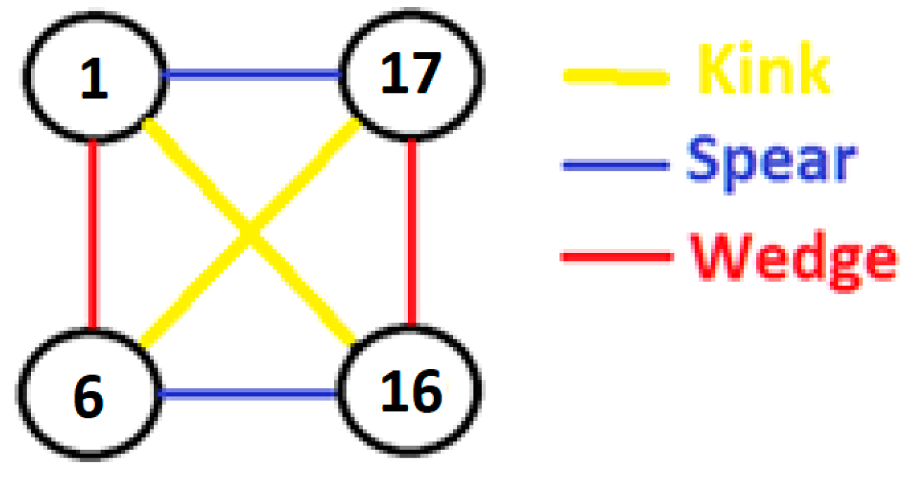
Figure 3.
(a) Image Quality map of two successive generations of variants, with residual austenite highlighted in orange. The Spear, Wedge, and Kink boundaries are highlighted in blue, red, and yellow, respectively. (b) Reconstructed variant map and (c) pole figure (black dots) and pole figure (green stars) of the average orientation of residual austenite (the variant number associated with each habit plane is indicated on the pole figure).
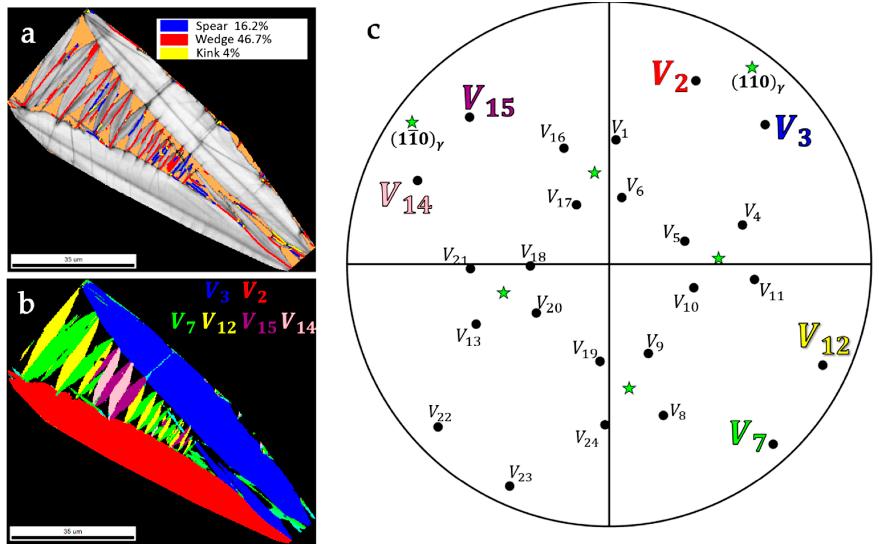
Figure 4.
Composite EBSD map. Variant of Figure 3 is color-coded according to the grain reference orientation deviation angle. Side variants are colour coded according to the IPF of the normal direction. Inset shows the misorientation profile across the black dotted line.
Figure 4.
Composite EBSD map. Variant of Figure 3 is color-coded according to the grain reference orientation deviation angle. Side variants are colour coded according to the IPF of the normal direction. Inset shows the misorientation profile across the black dotted line.
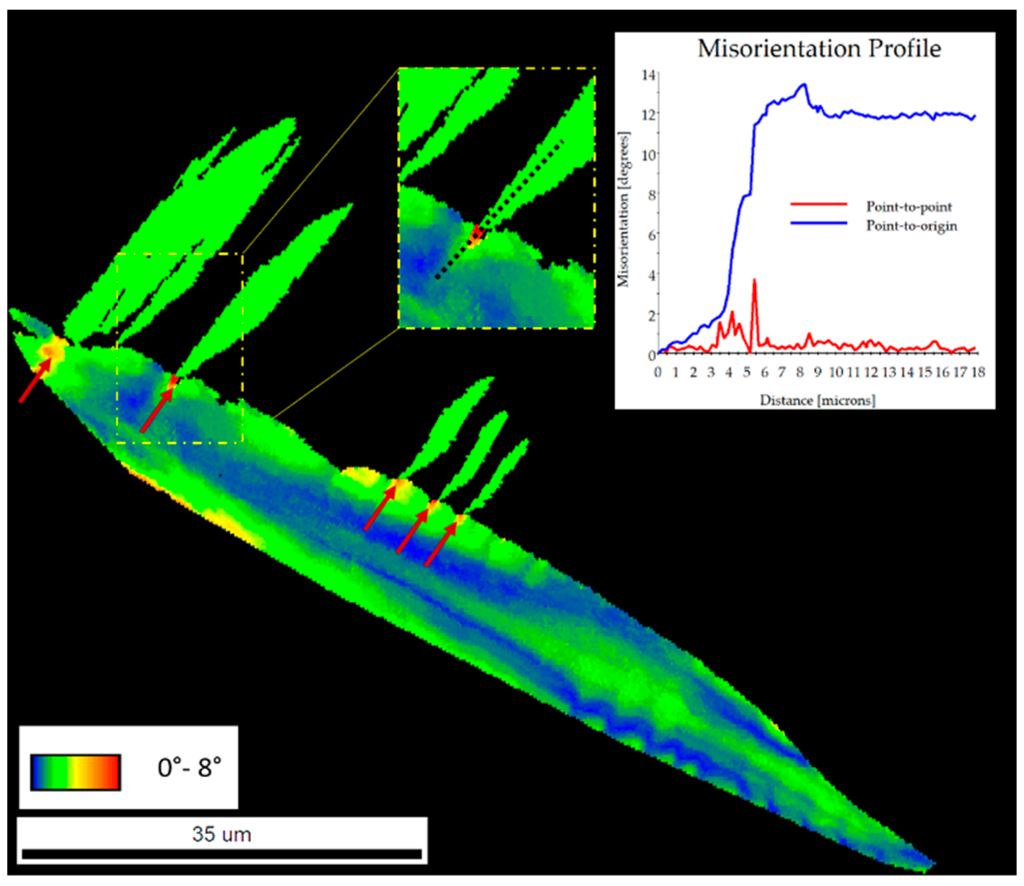
Figure 5.
SEM micrograph of the FG sample transformed under stress. Martensite is fully twinned. Residual austenite appears in light grey.
Figure 5.
SEM micrograph of the FG sample transformed under stress. Martensite is fully twinned. Residual austenite appears in light grey.
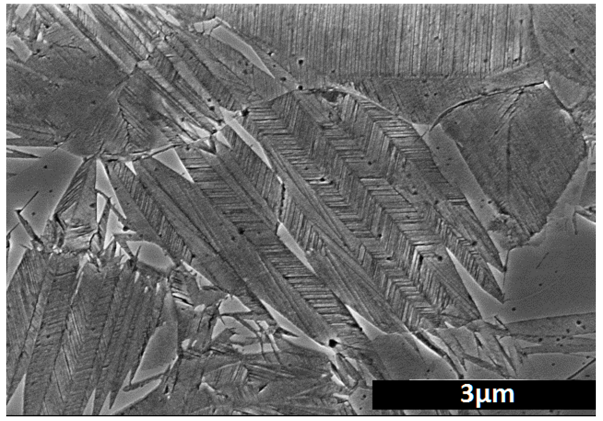
Figure 6.
(a) SEM micrograph of a self-accommodating plate group of variants in the FG sample. Theoretical traces of the Wedge, Spear, and Kink junctions are highlighted in red, blue, and yellow, respectively. (b) EBSD variant map of Figure 6a. (c) pole figure of residual austenite (green stars) together with the poles of the habit planes of the variants (black dots) reconstructed in Figure 6b. The poles of the habit planes of the variants formed in the present austenite grain gather around a common plane, that is, they belong to the same plate group PG2.
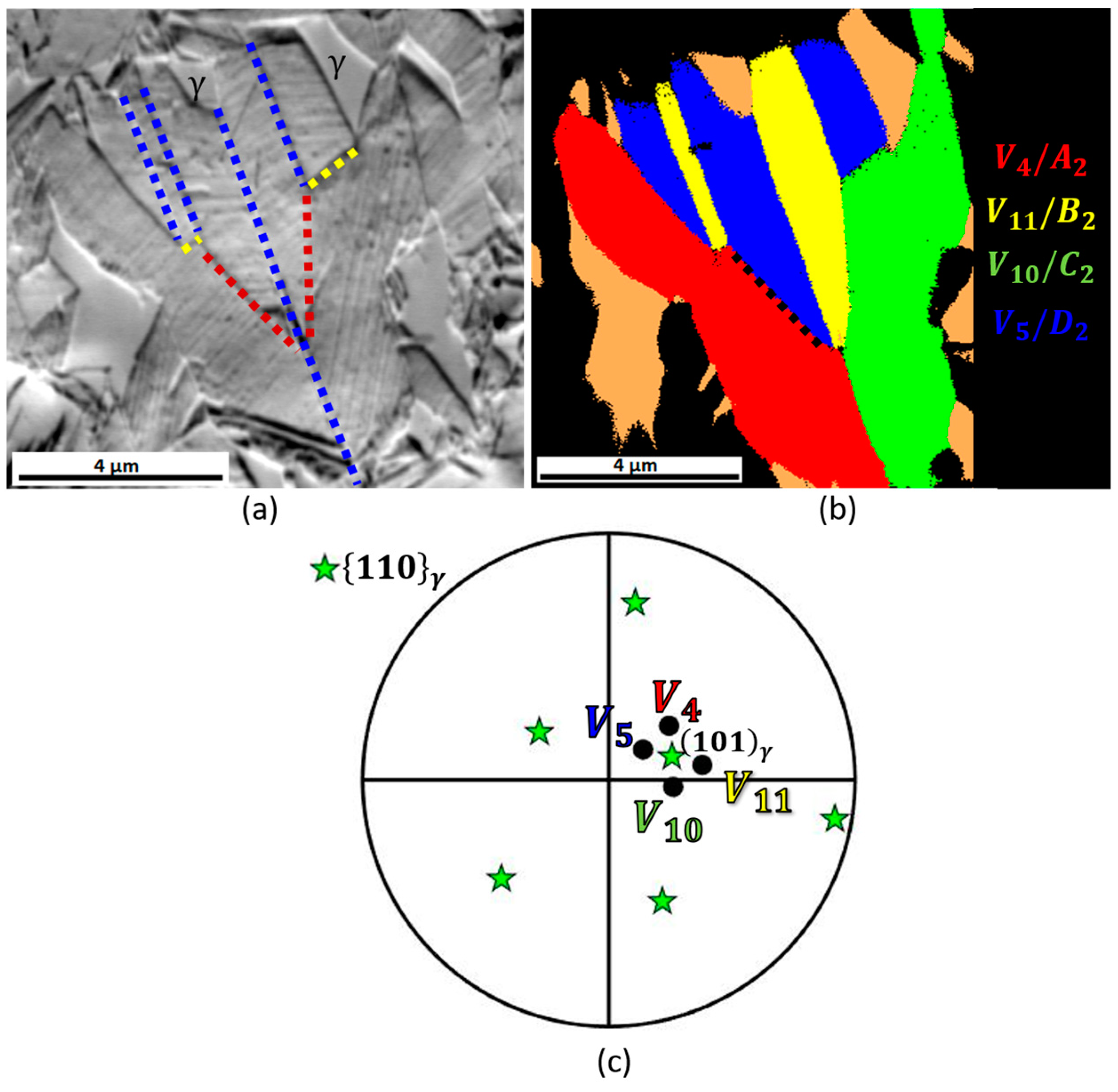
Figure 7.
(a) SEM micrograph of a triple junction involving all three possible JPs between variants of the same plate group. (b) EBSD variant map of a similar cluster formed in the austenite grain studied in Figure 6.
Figure 7.
(a) SEM micrograph of a triple junction involving all three possible JPs between variants of the same plate group. (b) EBSD variant map of a similar cluster formed in the austenite grain studied in Figure 6.

Figure 8.
Deviation (a) angle and axis (b) maps for the Kink junction /.

Figure 9.
Schematic representation of the formation of a hierarchical configuration of variants. (a) The for-mation of the first variant occurs at Ms and crosses the entire austenite grain. (b) The formation of this first variant is followed by the formation of a first zig-zag configuration of variants by self-accommodation. (c) When the undercooling below Ms is sufficient, a new variant perpendicular to a variant of the first generation is formed by a branching mechanism and (d) this variant induces the formation of a new zig-zag configuration of variants by self-accommodation.

Figure 10.
Macrography taken at room temperature (a) of the FG sample bent to 180° in liquid nitrogen after elastic recovery and (b) of the same sample after rapid heating to 873 K.
Figure 10.
Macrography taken at room temperature (a) of the FG sample bent to 180° in liquid nitrogen after elastic recovery and (b) of the same sample after rapid heating to 873 K.


Table 1.
Coupling factors, the angle between habit planes, and misorientation angle/axis for the variant pairs of Figure 3 (Axis are given with reference to martensite).
Table 1.
Coupling factors, the angle between habit planes, and misorientation angle/axis for the variant pairs of Figure 3 (Axis are given with reference to martensite).
| Variant Pair, Solution Type | Coupling Factor | Angle between HP | Misorientation Angle/Axis | |
|---|---|---|---|---|
| Inter-generational couplings | /, (NS) | 0.98 | 77° | 12.6° <−0.17 −0.7 0.7> |
| /, (XI) | −0.88 | 88° | 53.1° <−0.73 0.65 0.22> | |
| /, (X) | 0.86 | 73° | 19.3° <0 −0.11 0.99> | |
| /, (XI) | −0.88 | 88° | 53.1° <0.22 0.73 0.65> | |
| /, (NS) | 0.98 | 77° | 12.6° <0.7 0.17 −0.7> | |
| /, (XI) | −0.88 | 88° | 53.1° <0.22 −0,73 −0.65> | |
| /, (XI) | −0.88 | 88° | 53.1° <0.73 0.65 −0.22> | |
| /, (X) | 0.86 | 73° | 19.3° <0.11 0 −0.99> | |
| Intra-generational couplings | /, (II) | −0.85 | 15° | 56.6° <0.71 0.71 0> |
| /, (III) | 0.88 | 21° | 15.2° <0.25 −0.68 0.68> | |
| /, (III) | 0.88 | 21° | 15.2° <−0.68 0.25 −0.68> | |
| /, (I) | −0.88 | 26° | 51.4° <−0.44 −0.63 0.63> | |
| /, (I) | −0.88 | 26° | 51.4° <0.44 0.63 0.63> | |
| /, (II) | −0.85 | 15° | 56.6° <−0.71 0.71 0> | |
| /, (II) | −0.85 | 15° | 56.6° <0.71 −0.71 0> |
Table 2.
Indices of the junction planes (JP) and deviation from the invariant plane condition for all the pairs of variants of PG2.
Table 2.
Indices of the junction planes (JP) and deviation from the invariant plane condition for all the pairs of variants of PG2.
| Solution Type | Variant Pairs | JP (in Austenite) | Deviation from Invariant Plane Condition (Angle/Axis) |
|---|---|---|---|
| I (Spear) | / / | 0.043° | |
| II (Wedge) | / / | 0.6° 0.6° | |
| III (Kink) | / / | 5.01° 5.01° |
Disclaimer/Publisher’s Note: The statements, opinions and data contained in all publications are solely those of the individual author(s) and contributor(s) and not of MDPI and/or the editor(s). MDPI and/or the editor(s) disclaim responsibility for any injury to people or property resulting from any ideas, methods, instructions or products referred to in the content. |
© 2024 by the authors. Licensee MDPI, Basel, Switzerland. This article is an open access article distributed under the terms and conditions of the Creative Commons Attribution (CC BY) license (https://creativecommons.org/licenses/by/4.0/).
Share and Cite
MDPI and ACS Style
Malet, L.; Godet, S. Influence of Austenite Grain Size on the Variant Configurations of Martensite in a Fe-30.5Ni-0.155C Alloy. Crystals 2024, 14, 461. https://doi.org/10.3390/cryst14050461
AMA Style
Malet L, Godet S. Influence of Austenite Grain Size on the Variant Configurations of Martensite in a Fe-30.5Ni-0.155C Alloy. Crystals. 2024; 14(5):461. https://doi.org/10.3390/cryst14050461
Chicago/Turabian StyleMalet, Loïc, and Stéphane Godet. 2024. "Influence of Austenite Grain Size on the Variant Configurations of Martensite in a Fe-30.5Ni-0.155C Alloy" Crystals 14, no. 5: 461. https://doi.org/10.3390/cryst14050461
Note that from the first issue of 2016, this journal uses article numbers instead of page numbers. See further details here.