
Broadening Bandwidth in a Semi-Active Vibration Absorption System Utilizing Stacked Polyvinyl Chloride Gel Actuators
 and
and
Abstract
:1. Introduction
2. Fabrication and Mechanism of PVC Gel Actuator
2.1. Composition and Fabrication of PVC Gels
2.2. Deformation Mechanism of PVC Gel Actuator
2.3. Structure of a Stacked PVC gel Actuator
3. Mechanical and Actuating Characterization of the Stacked PVC Gel Actuator
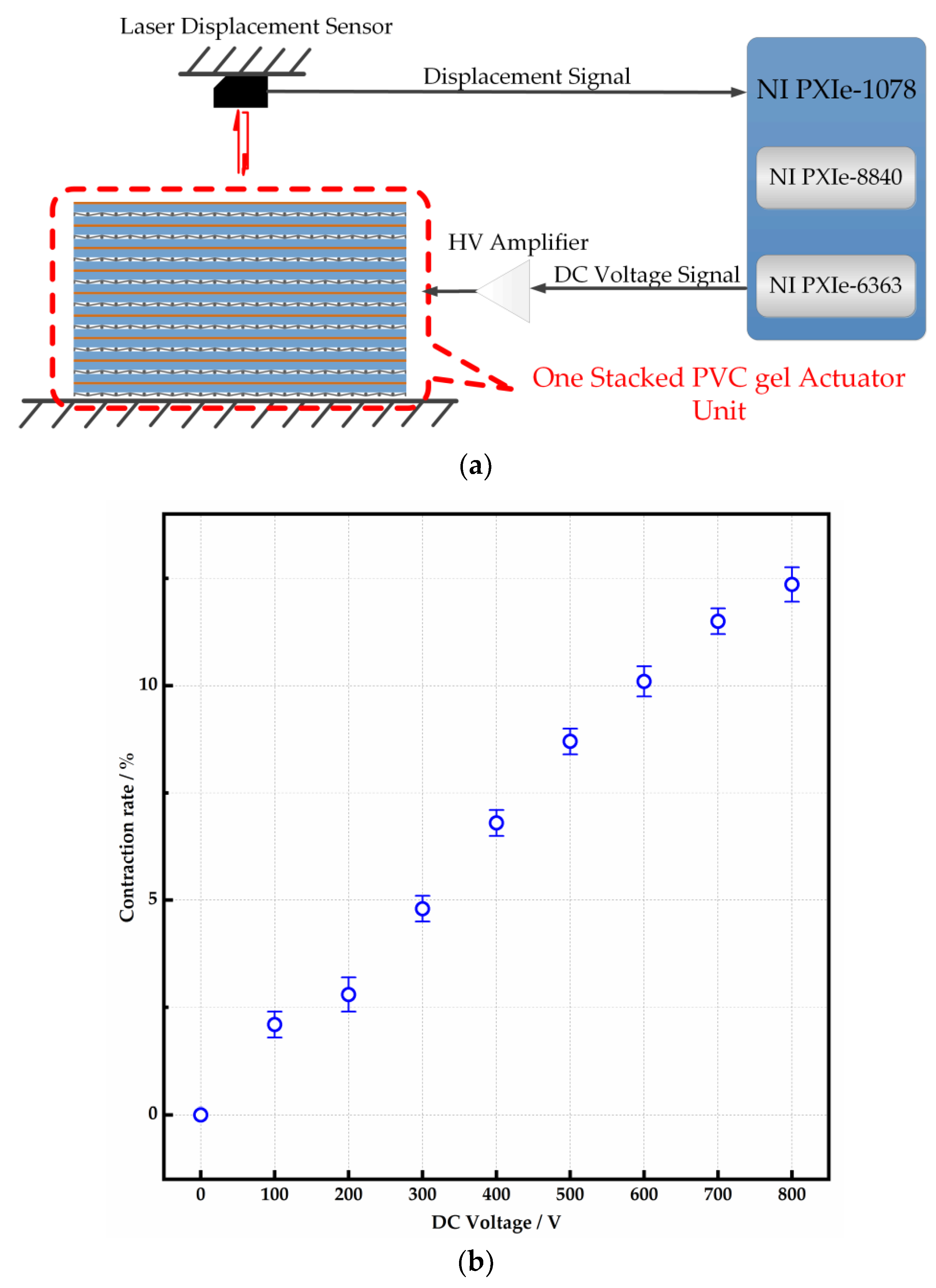
3.1. Deformation Measurement
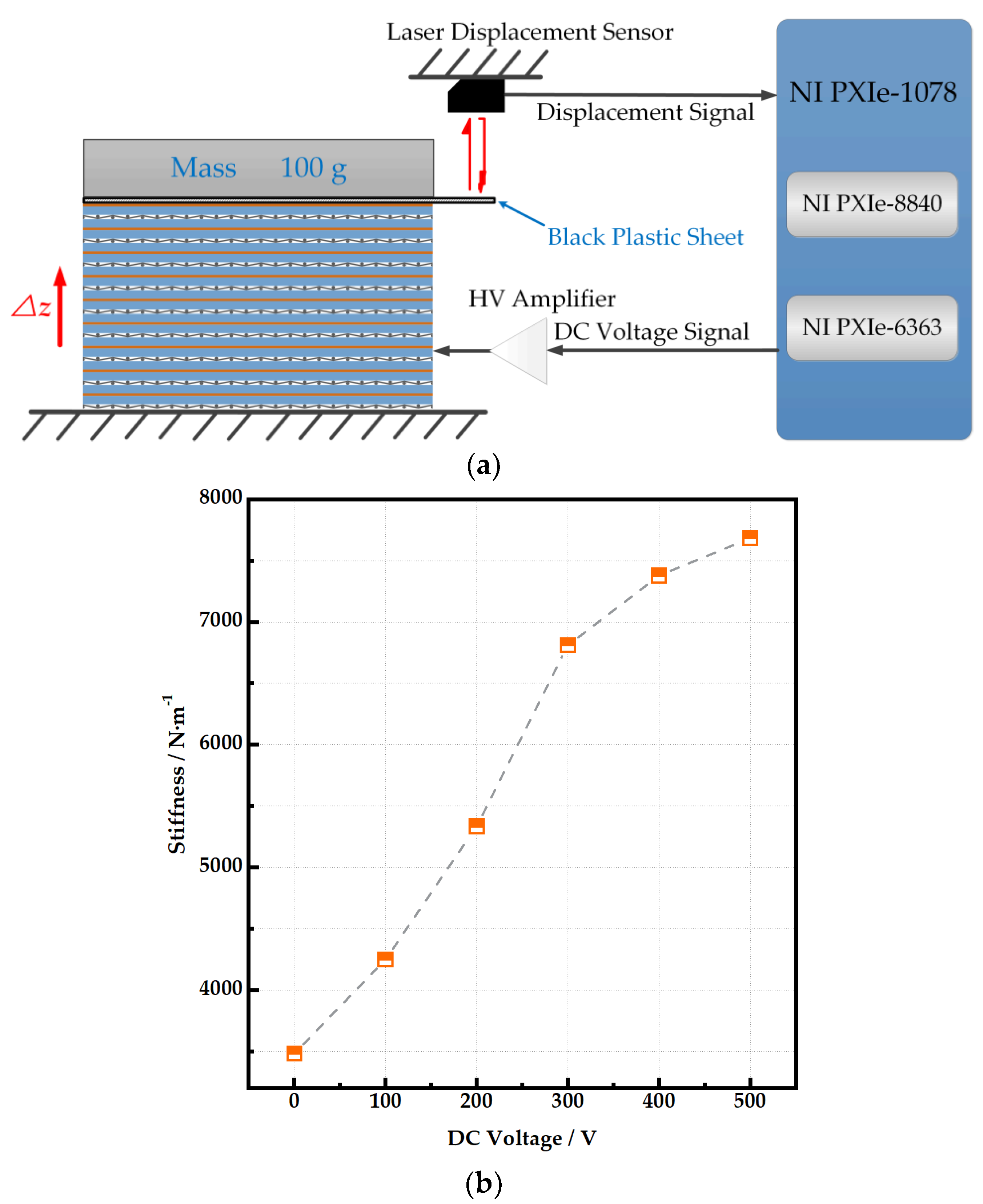
3.2. The Vertical Stiffness of the Stacked PVC Gel Actuator Units
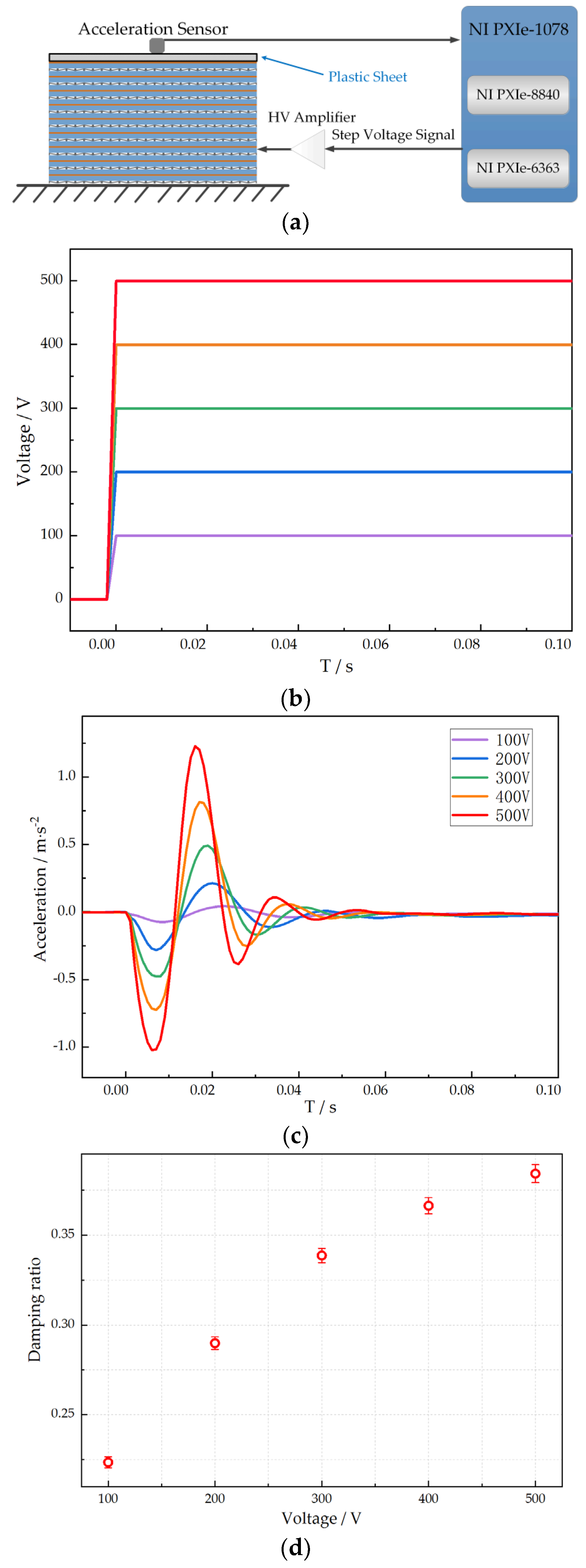
3.3. The Damping Ratio Test of the Stacked PVC Gel Actuator Units
3.4. Dynamic Response of the PVC Gel Absorber
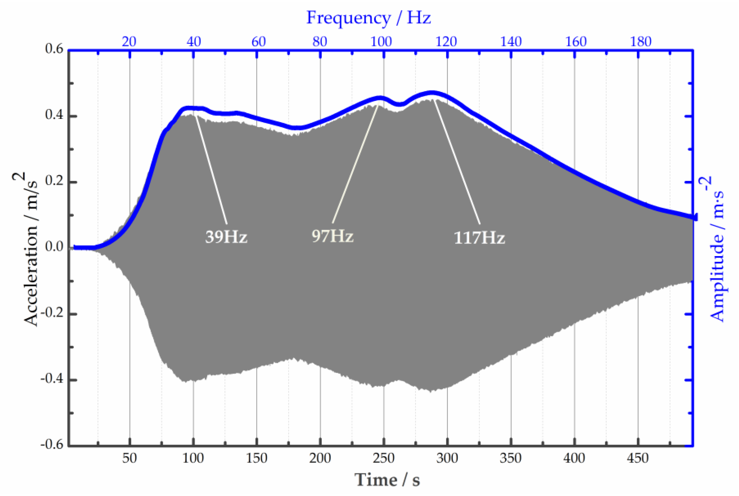
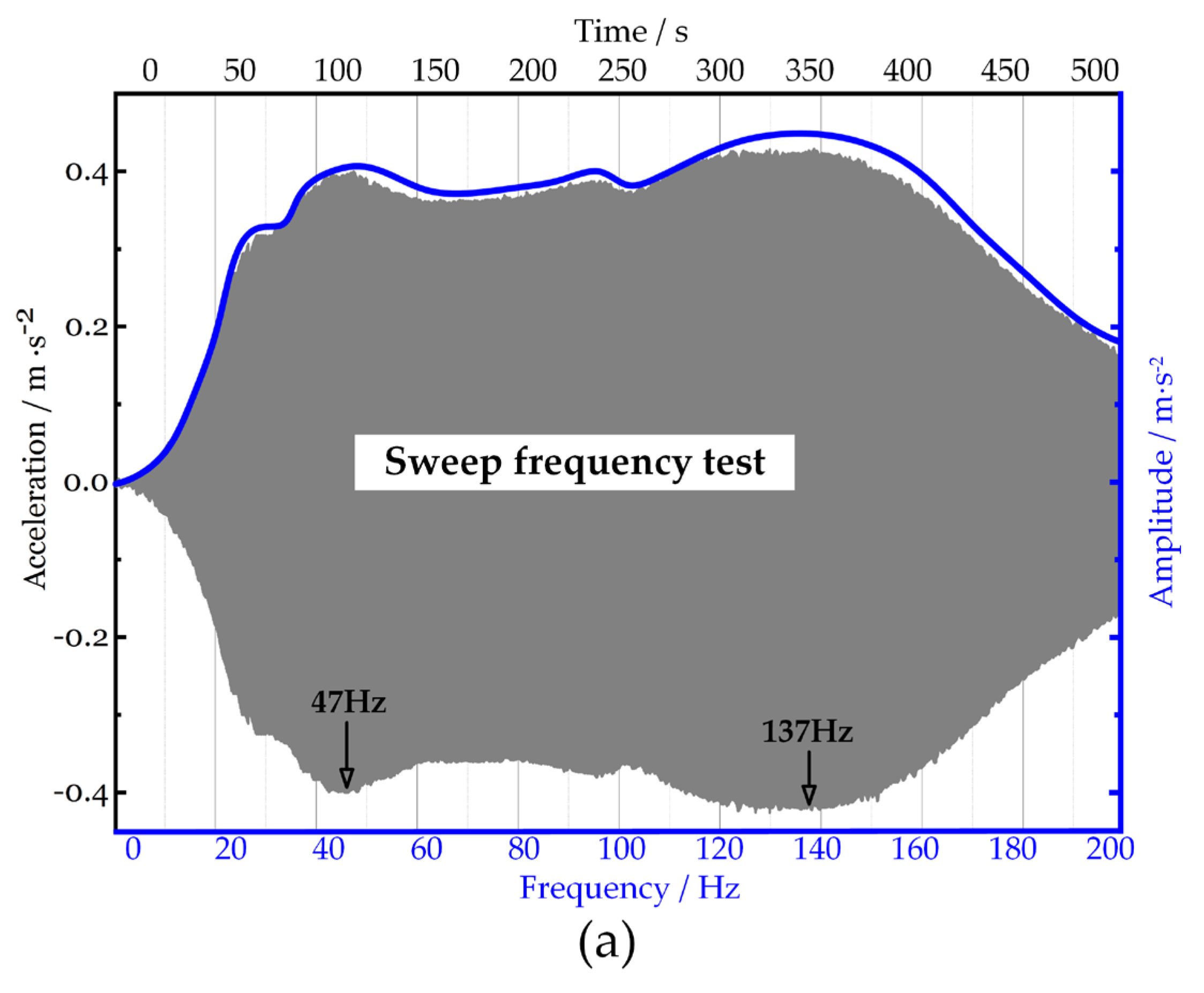
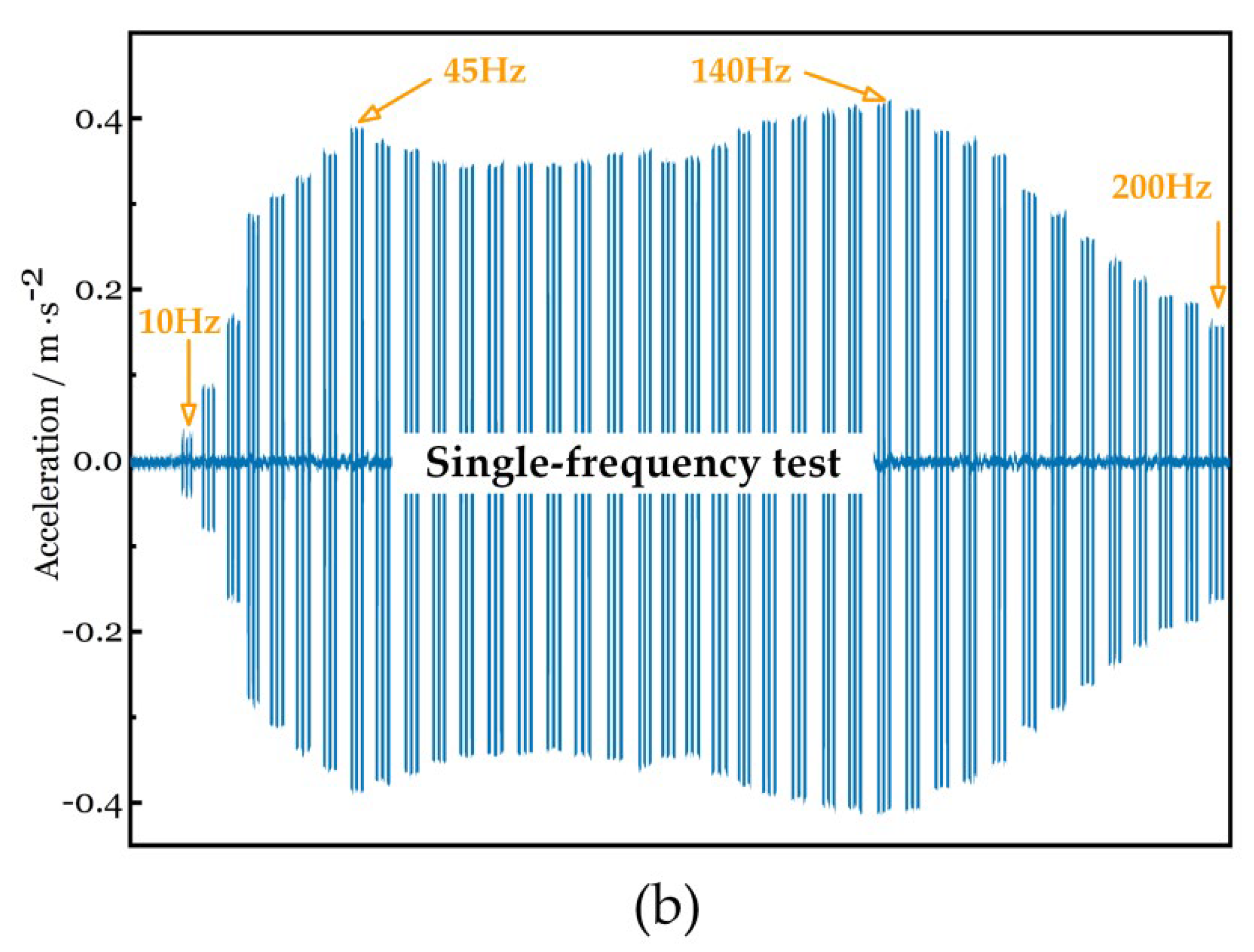
3.4.1. Characterization of Wide Absorption Bandwidth
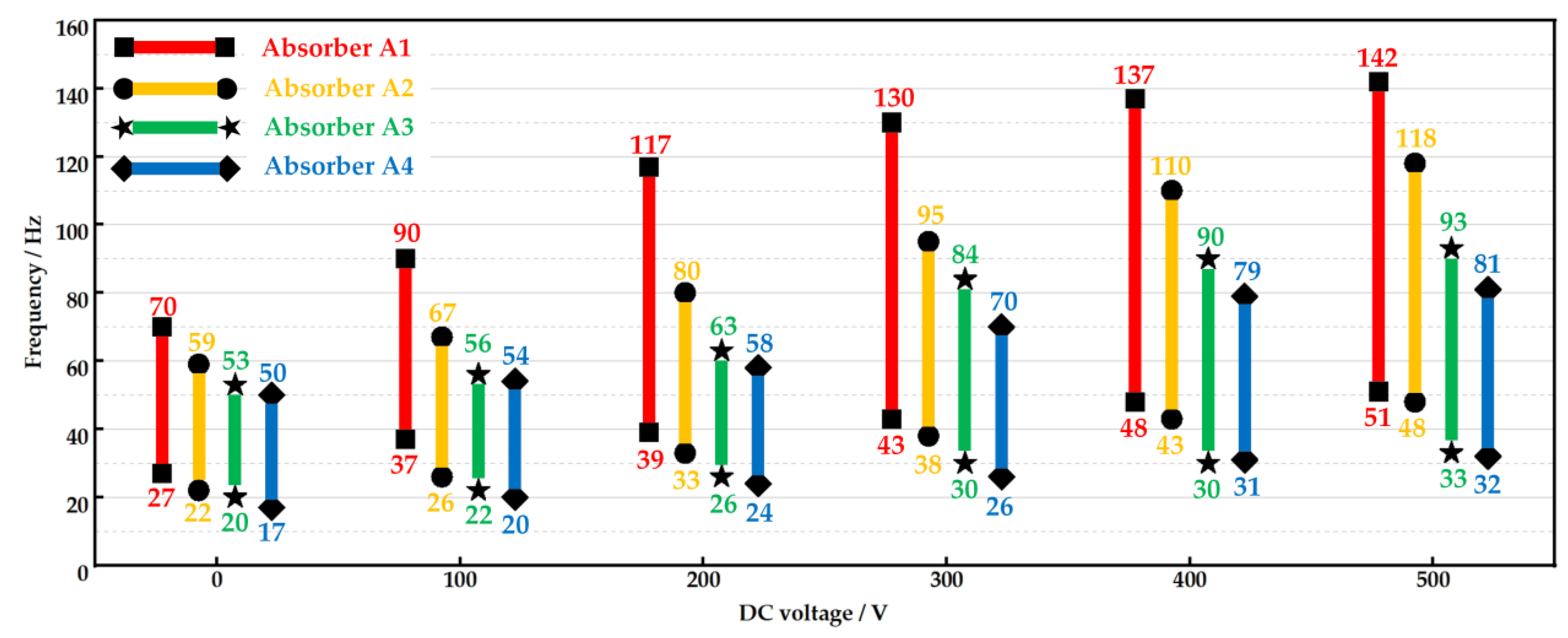
3.4.2. Alterable Absorption Bandwidth
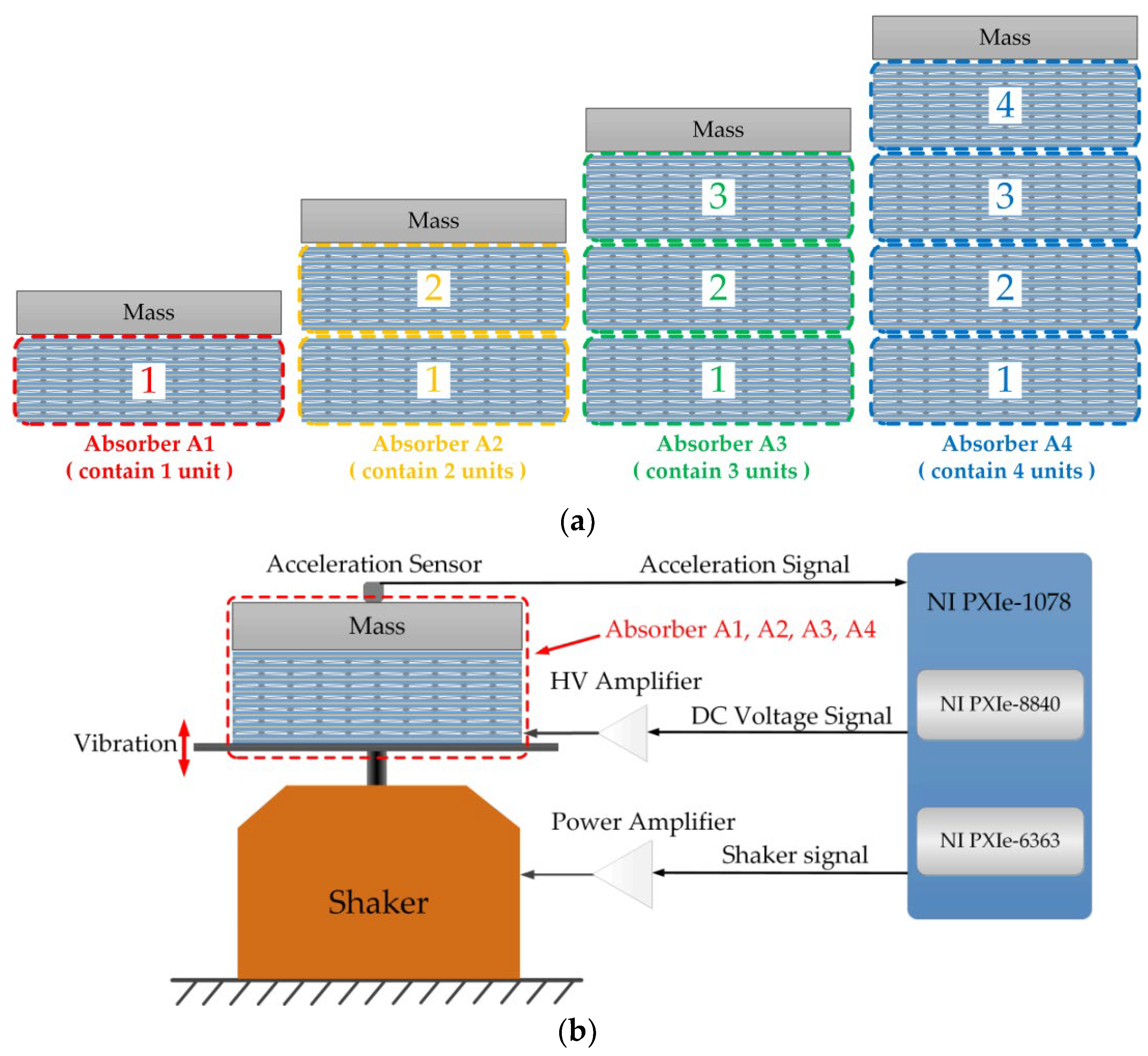
3.4.3. The Influence of Unit Numbers in the Stacked PVC Gel Actuators
3.4.4. Selection of PVC Gel Absorber
4. Application of PVC Gels Absorber in Semi-Active Vibration Control
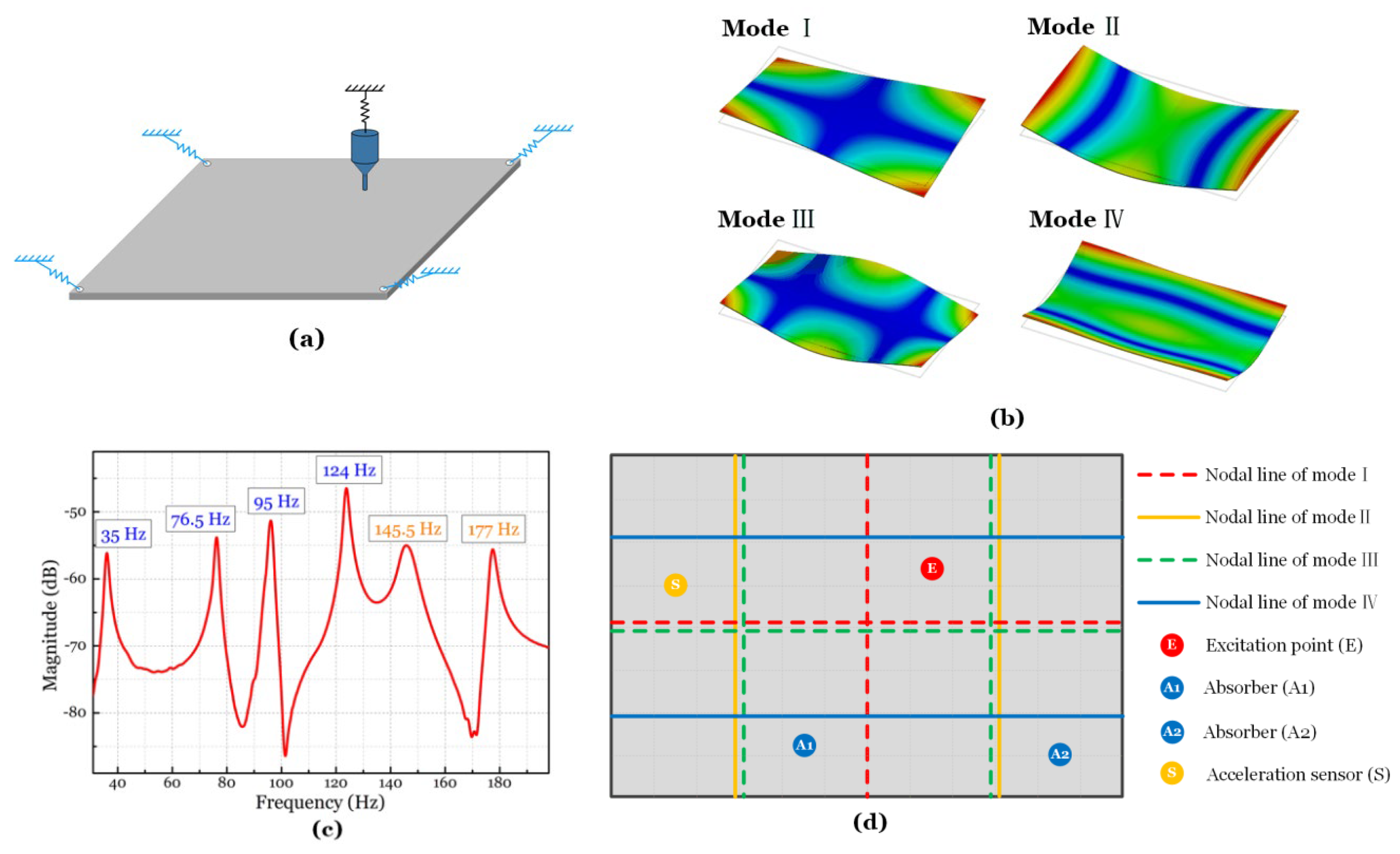
4.1. A vibrating Plate as a Platform
4.2. Semi-Active Vibration Control Strategy
4.3. Results and Discussion
5. Conclusions
Author Contributions
Funding
Data Availability Statement
Conflicts of Interest
References
- Kinji, A.; Hidernori, O. Soft Actuators; Springer: Berlin/Heidelberg, Germany, 2012; pp. 169–183. [Google Scholar]
- Li, Y.; Maeda, Y.; Hashimoto, M. Lightweight, Soft Variable Stiffness Gel Spats for Walking Assistance. Int. J. Adv. Robot. Syst. 2015, 12, 175. [Google Scholar] [CrossRef]
- Li, Y.; Hashimoto, M. Design and prototyping of a novel lightweight walking assist wear using PVC gel soft actuators. Sens. Actuators A Phys. 2016, 239, 26–44. [Google Scholar] [CrossRef]
- Li, Y.; Hashimoto, M. PVC Gel Soft Actuator-Based Wearable Assist Wear for Hip Joint Support during Walking. Smart Mater. Struct. 2017, 26, 125003. [Google Scholar] [CrossRef]
- Bae, J.W.; Shin, E.J.; Jeong, J.; Choi, D.S.; Lee, J.E.; Nam, B.U.; Lin, L.; Kim, S.-Y. High-Performance PVC Gel for Adaptive Micro-Lenses with Variable Focal Length. Sci. Rep. 2017, 7, 2068. [Google Scholar] [CrossRef] [PubMed]
- Shibagaki, M.; Matsuki, T.; Hashimoto, M. Application of a contraction type PVC gel actuator to brakes. In Proceedings of the 2010 IEEE International Conference on Mechatronics and Automation, Xi’an, China, 4–7 August 2010. [Google Scholar]
- Ali, M.; Hirai, T. Characteristics of the creep-induced bending deformation of a PVC gel actuator by an electric field. J. Mater. Sci. 2011, 46, 7681–7688. [Google Scholar] [CrossRef]
- Cheng, X. Understanding the electro-stimulated deformation of PVC gel by in situ Raman spectroscopy. Polym. Test. 2017, 65, 90–96. [Google Scholar] [CrossRef]
- Hashimoto, M. Development of an Artificial Muscle Using PVC Gel. In Proceedings of the ASME 2011 International Mechanical Engineering Congress and Exposition, Denver, CO, USA, 11–17 November 2011. [Google Scholar]
- Li, Y. Influence of the number of stacked layers on the performance of PVC gel actuators. In Proceedings of the IEEE/ASME International Conference on Advanced Intelligent Mechatronics, Besacon, France, 8–11 July 2014. [Google Scholar]
- Li, Z. Stacked dielectric elastomer actuator (SDEA): Casting process, modeling and active vibration isolation. Smart Mater. Struct. 2018, 27, 075023. [Google Scholar] [CrossRef]
- Ogawa, N. Characteristics evaluation of PVC gel actuators. In Proceedings of the IEEE/RSJ International Conference on Intelligent Robots and Systems, St. Louis, MO, USA, 10–15 October 2009. [Google Scholar]
- Yamano, M. A contraction type soft actuator using poly vinyl chloride gel. In Proceedings of the IEEE International Conference on Robotics and Biomimetics, Bangkok, Thailand, 22–25 February 2009. [Google Scholar]
- Hirai, T.; Hong, X.; Hirai, K. The effects of adding ionic liquids to plasticized PVC gel actuators. In Proceedings of the IEEE International Conference on Mechatronics and Automation, Xi’an, China, 4–7 August 2010; pp. 71–76. [Google Scholar]
- Li, Y.; Hashimoto, M. Low-voltage planar PVC gel actuator with high performances. Sens. Actuators B Chem. 2018, 282C, 482–489. [Google Scholar]
- Tokoro, H.; Hashimoto, M. Characteristics of a non-woven PVC gel actuator. In Proceedings of the IEEE/ASME International Conference on Advanced Intelligent Mechatronics, Besacon, France, 8–11 July 2014. [Google Scholar]
- Wang, Z. 3D Printing of Electrically Responsive PVC Gel Actuators. ACS Appl. Mater. Interfaces 2021, 13, 24164–24172. [Google Scholar] [CrossRef]
- Li, Y.; Hashimoto, M. PVC Gel based Artificial Muscles: Characterizations and Actuation Modular Constructions. Sens. Actuators A Phys. 2015, 233, 246–258. [Google Scholar] [CrossRef]
- Ali, M.; Hirai, T. Relationship between electrode polarization and electrical actuation of dielectric PVC gel actuators. Soft Matter 2012, 8, 3694. [Google Scholar] [CrossRef]
- Kinji, A.; Minoru, H. Electrical Properties and Electromechanical Modeling of Plasticized PVC Gel Actuators. Sens. Actuators B Chem. 2018, 273, 1246–1256. [Google Scholar]
- Shibagaki, M.; Ogawa, N.; Hashimoto, M. Modeling of a contraction type PVC gel actuator. In Proceedings of the IEEE International Conference on Robotics and Biomimetics, Tianjin, China, 14–18 December 2010. [Google Scholar]
- Hermann, F. Device for Damping Vibrations of Bodies. U.S. Patent US0989958, 18 April 1911. [Google Scholar]
- Bekdas, G.; Nigdeli, S.M. Mass ratio factor for optimum tuned mass damper strategies. Int. J. Mech. Sci. 2013, 71, 68–84. [Google Scholar] [CrossRef]
- Brennan, M.J. Some Recent Developments in Adaptive Tuned Vibration Absorbers/Neutralisers. Shock Vib. 2006, 13, 531–543. [Google Scholar] [CrossRef]
- Rubio, L. Optimization of passive vibration absorbers to reduce chatter in boring. Mech. Syst. Signal Process. 2013, 41, 691–704. [Google Scholar] [CrossRef]
- Sarkar, S.; Chakraborty, A. Development of semi-active vibration control strategy for horizontal axis wind turbine tower using multiple magneto-rheological tuned liquid column dampers. J. Sound Vib. 2019, 457, 15–36. [Google Scholar] [CrossRef]
- Albanese, A.M.; Cunefare, K.A. Properties of a magnetorheological semi-active vibration absorber. In Proceedings of the Smart Structures and Materials 2003: Damping and Isolation, San Diego, CA, USA, 2–6 March 2003; pp. 36–43. [Google Scholar]
- Deng, H.X.; Gong, X.L. Application of magnetorheological elastomer to vibration absorber. Commun. Nonlinear Sci. Numer. Simul. 2008, 13, 1938–1947. [Google Scholar] [CrossRef]
- Gao, P. Design of the frequency tuning scheme for a semi-active vibration absorber. Mech. Mach. Theory 2019, 140, 641–653. [Google Scholar] [CrossRef]
- Hyun, K.K.; Hye, S.K. Stiffness control of magnetorheological gels for adaptive tunable vibration absorber. Smart Mater. Struct. 2017, 26, 015016. [Google Scholar]
- Liu, X. Development of a Semi-Active Electromagnetic Vibration Absorber and Its Experimental Study. J. Vib. Acoust. 2013, 135, 510151–510159. [Google Scholar] [CrossRef]
- Sun, S. An adaptive tuned vibration absorber based on multilayered mr elastomers. Smart Mater. Struct. 2015, 24, 045045. [Google Scholar] [CrossRef]
- Weber, F. Semi-active vibration absorber based on real-time controlled MR damper. Mech. Syst. Signal Process. 2014, 46, 272–288. [Google Scholar] [CrossRef]
- Mane, P.U.; Kondekar, G.R. Experimental study on vibration control using shape memory alloy based vibration absorber. Mater. Today Proc. 2021, 45, 2812–2817. [Google Scholar] [CrossRef]
- Bein, T. Smart interfaces and semi-active vibration absorber for noise reduction in vehicle structures. Aerosp. Sci. Technol. 2008, 12, 62–73. [Google Scholar] [CrossRef]
- Casagrande, D.; Gardonio, P.; Zilletti, M. Smart panel with time-varying shunted piezoelectric patch absorbers for broadband vibration control. J. Sound Vib. 2015, 400, 288–304. [Google Scholar] [CrossRef]
- Jalili, N.; Iv, D.W.K. Structural vibration control using an active resonator absorber: Modeling and control implementation. Smart Mater. Struct. 2004, 13, 998–1005. [Google Scholar] [CrossRef]
- Benacchio, S. Design of a Magnetic Vibration Absorber with Tunable Stiffnesses. Nonlinear Dyn. 2016, 85, 893–911. [Google Scholar] [CrossRef]
- Bonello, P.; Brennan, M.J.; Elliott, S.J. Vibration control using an adaptive tuned vibration absorber with a variable curvature stiffness element. Smart Mater. Struct. 2005, 14, 1055–1065. [Google Scholar] [CrossRef]
- Ji, H. A Vibration Absorber Based on Two-dimensional Acoustic Black Holes. J. Sound Vib. 2021, 500, 116024. [Google Scholar] [CrossRef]
- Su, T.S. Efficient Vibration Control with a Semi-Active Vibration Absorber in a Semiconductor Fab. Appl. Mech. Mater. 2014, 564, 143–148. [Google Scholar] [CrossRef]
- Sven, H.; Dirk, M. Adaptive Piezoelectric Absorber for Active Vibration Control. Actuators 2016, 5, 7. [Google Scholar] [CrossRef]
- Xi, W.; Yang, B.; Hu, Y. Optimal Design and Experimental Study of a Multidynamic Vibration Absorber for Multifrequency Excitation. J. Vib. Acoust. 2017, 139, 031011.1–031011.7. [Google Scholar]
- Wang, X. Coarse-fine adaptive tuned vibration absorber with high frequency resolution. J. Sound Vib. 2016, 383, 46–63. [Google Scholar] [CrossRef]
- Wang, X. Nonlinear convergence active vibration absorber for single and multiple frequency vibration control. J. Sound Vib. 2017, 411, 289–303. [Google Scholar] [CrossRef]
- Wang, X.; Yang, B. Transient vibration control using nonlinear convergence active vibration absorber for impulse excitation. Mech. Syst. Signal Process. 2019, 117, 425–436. [Google Scholar] [CrossRef]


| PVC Gel Membrane | Anode | Cathode | |
|---|---|---|---|
| Material | PVC:DBA = 1:4 | Stainless mesh (#60) | Copper foil |
| Size | 35 × 35 × 0.4 mm | 32 × 32 × 0.2 mm | 32 × 32 × 0.02 mm |
| Number | 17 | 9 | 9 |
| Unit’s height | 9.2 mm | Unit’s weight | 8.8 g |
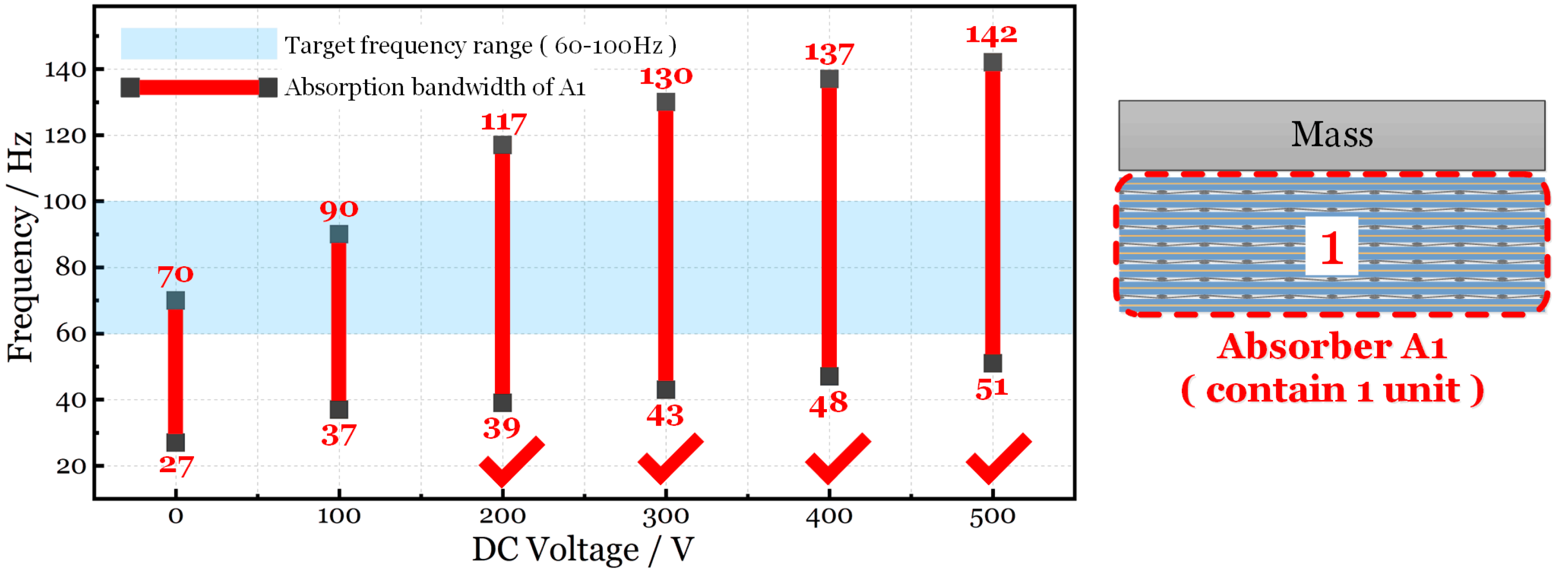
| Target Frequency Range (INVLTarget) | DC Voltage | Absorption Bandwidth of Absorber A1 (INVLA1) | INVLA1 Covers INVLTarget or Not? |
|---|---|---|---|
| (60 Hz, 100 Hz) | 0 V | (27 Hz, 70 Hz) | No |
| 100 V | (37 Hz, 90 Hz) | No | |
| 200 V | (39 Hz, 117 Hz) | Yes | |
| 300 V | (43 Hz, 130 Hz) | Yes | |
| 400 V | (47 Hz, 137 Hz) | Yes | |
| 500 V | (51 Hz, 142 Hz) | Yes |
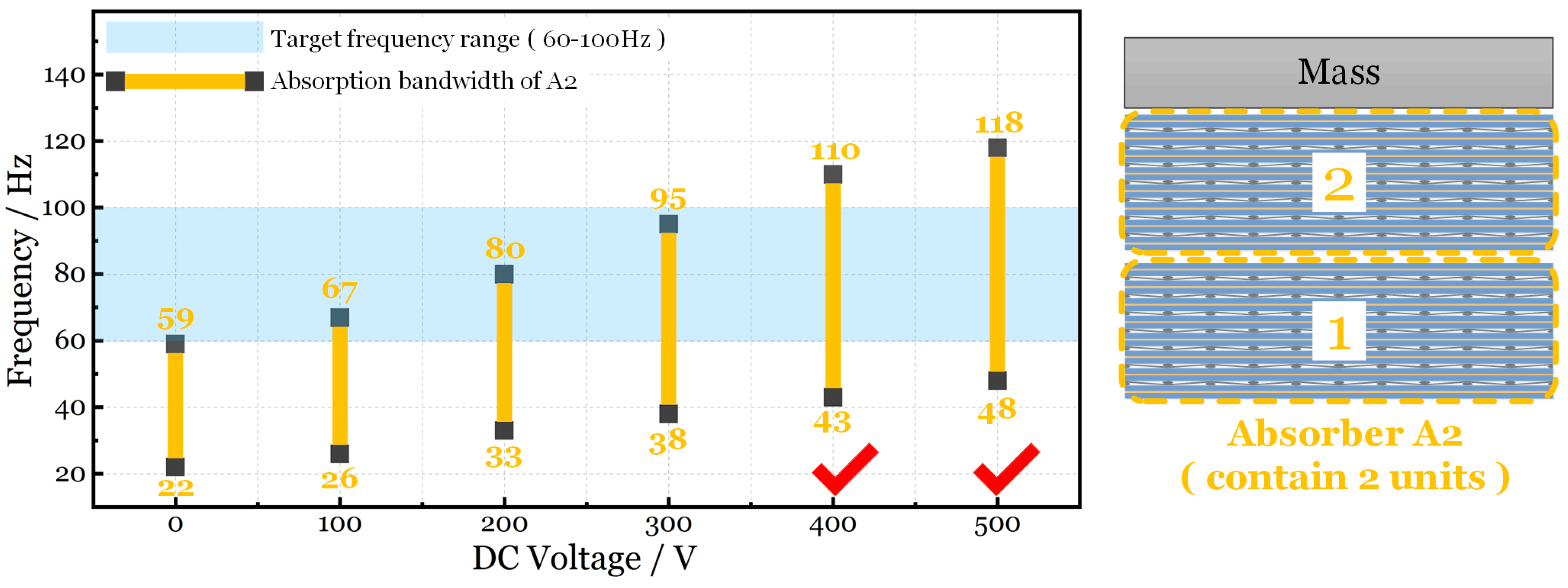
| Target Frequency Range (INVLTarget) | DC Voltage | Absorption Bandwidth of Absorber A2 (INVLA2) | INVLA2 Covers INVLTarget or Not? |
|---|---|---|---|
| (60 Hz, 100 Hz) | 0 V | (22 Hz, 59 Hz) | No |
| 100 V | (26 Hz, 67 Hz) | No | |
| 200 V | (33 Hz, 80 Hz) | No | |
| 300 V | (38 Hz, 95 Hz) | No | |
| 400 V | (43 Hz, 110 Hz) | Yes | |
| 500 V | (48 Hz, 118 Hz) | Yes |
| DC Voltage Applied to A1/V | |||||||
|---|---|---|---|---|---|---|---|
| 0 | 100 | 200 | 300 | 400 | 500 | ||
| DC voltage applied to A2/V | 500 | (27, 118) | (37, 118) | (39, 118) | (43, 130) | (48, 137) | (48, 142) |
| 400 | (27, 110) | (37, 110) | (39, 117) | (43, 130) | (43, 137) | (43, 142) | |
| 300 | (27, 95) | (37, 95) | (38, 117) | (38, 130) | (38, 137) | (38, 142) | |
| 200 | (27, 80) | (33, 90) | (33, 117) | (33, 130) | (33, 137) | (33, 142) | |
| 100 | (26, 70) | (26, 90) | (26, 117) | (26, 130) | (26, 137) | (26, 142) | |
| 0 | (22, 70) | (22, 90) | (22, 117) | (22, 130) | (22, 137) | (22, 142) | |
 The interval which can cover the target frequency range (35–124 Hz) The interval which can cover the target frequency range (35–124 Hz) | |||||||
| VDC (V) | Absorption Bandwidth (Hz) | Natural Frequency of the Plate (Hz) | |||
|---|---|---|---|---|---|
| 0 | 27–70 | 35 (I) | 76.5 (II) | 95 (III) | 124 (IV) |
| 100 | 37–90 | ||||
| 200 | 39–117 | ||||
| 300 | 43–130 | ||||
| 400 | 47–137 | ||||
| 500 | 51–142 | ||||
Disclaimer/Publisher’s Note: The statements, opinions and data contained in all publications are solely those of the individual author(s) and contributor(s) and not of MDPI and/or the editor(s). MDPI and/or the editor(s) disclaim responsibility for any injury to people or property resulting from any ideas, methods, instructions or products referred to in the content. |
© 2024 by the authors. Licensee MDPI, Basel, Switzerland. This article is an open access article distributed under the terms and conditions of the Creative Commons Attribution (CC BY) license (https://creativecommons.org/licenses/by/4.0/).
Share and Cite
Li, Z.; Liu, C.; Sheng, M.; Wang, M.; Chen, H.; Li, B.; Xia, P. Broadening Bandwidth in a Semi-Active Vibration Absorption System Utilizing Stacked Polyvinyl Chloride Gel Actuators. Micromachines 2024, 15, 649. https://doi.org/10.3390/mi15050649
Li Z, Liu C, Sheng M, Wang M, Chen H, Li B, Xia P. Broadening Bandwidth in a Semi-Active Vibration Absorption System Utilizing Stacked Polyvinyl Chloride Gel Actuators. Micromachines. 2024; 15(5):649. https://doi.org/10.3390/mi15050649
Chicago/Turabian StyleLi, Zhuoyuan, Chen Liu, Meiping Sheng, Minqing Wang, Hualing Chen, Bo Li, and Peng Xia. 2024. "Broadening Bandwidth in a Semi-Active Vibration Absorption System Utilizing Stacked Polyvinyl Chloride Gel Actuators" Micromachines 15, no. 5: 649. https://doi.org/10.3390/mi15050649