Article

Enhanced Long-Term Corrosion Resistance of 316L Stainless Steel by Multilayer Amorphous Carbon Coatings

1
Key Laboratory of Advanced Marine Materials, Ningbo Institute of Materials Technology and Engineering, Chinese Academy of Sciences, Ningbo 315201, China
2
Center of Materials Science and Optoelectronics Engineering, University of Chinese Academy of Sciences, Beijing 100049, China
3
School of Materials Science and Physics, China University of Mining and Technology, Xuzhou 221116, China
*
Authors to whom correspondence should be addressed.
Materials 2024, 17(9), 2129; https://doi.org/10.3390/ma17092129
Submission received: 29 March 2024 / Revised: 17 April 2024 / Accepted: 29 April 2024 / Published: 1 May 2024
(This article belongs to the Special Issue Friction, Corrosion and Protection of Material Surfaces)

Abstract

:
Diamond-like carbon (DLC) coatings are effective in protecting the key components of marine equipment and can greatly improve their short-term performance (1.5~4.5 h). However, the lack of investigation into their long-term (more than 200 h) performance cannot meet the service life requirements of marine equipment. Here, three multilayered DLC coatings, namely Ti/DLC, TiCx/DLC, and Ti-TiCx/DLC, were prepared, and their long-term corrosion resistance was investigated. Results showed that the corrosion current density of all DLC coatings was reduced by 1–2 orders of magnitude compared with bare 316L stainless steel (316Lss). Moreover, under long-term (63 days) immersion in a 3.5 wt.% NaCl solution, all DLC coatings could provide excellent long-term corrosion protection for 316Lss, and Ti-TiCx/DLC depicted the best corrosion resistance; the polarization resistances remained at ~3.0 × 10⁷ Ω·cm2 after immersion for 63 days, with more interfaces to hinder the penetration of the corrosive media. Meanwhile, during neutral salt spray (3000 h), the corrosion resistance of Ti/DLC and TiCx/DLC coatings showed a certain degree of improvement because the insoluble corrosion products at the defects blocked the subsequent corrosion. This study can provide a route to designing amorphous carbon protective coatings for long-term marine applications in different environments.

1. Introduction

With the rapid advancement of the ocean economy, an increasing amount of marine engineering equipment is being produced and utilized for ocean measurement, observation, and forecasting. Meanwhile, in seawater, certain essential components of marine equipment, such as manipulators and environmental monitoring systems, encounter a range of challenges, such as scratch and corrosion problems [1,2,3,4,5]. Surface and coating technology are effective methods to extend the service life of those crucial components and realize their reliable operation without altering the fundamental characteristics of the substrate materials [6,7,8,9].
Among various coatings, diamond-like carbon (DLC) coatings are extensively used as scratch-resistant and anti-corrosion coatings for metal materials due to their high hardness and excellent chemical stability [10,11,12,13,14]. Recent efforts have seen a surge in the exploration of various DLC coatings for application in marine environments, showcasing enhanced performance over short durations [15,16]. For example, Totolin et al. found that the W-doped DLC coatings could effectively improve the tribocorrosion performance of the substrates in artificial seawater within 4.5 h [17]. Wei et al. confirmed that the incorporation of a multilayer structure can endow DLC coatings with improved anti-corrosion protection for 0.5 h. However, the presence of microdefects was identified as a pivotal constraint limiting their electrochemical corrosion resistance [18]. In light of the potential mechanical wear and tear experienced in marine settings, Li et al. designed a Cr/DLC multilayered film with a thickened top layer, which exhibited outstanding corrosion and tribocorrosion resistance in artificial seawater over a testing period of 1.5 h [19].
Meanwhile, in consideration of the long-term immersion conditions in a marine corrosive environment, DLC coatings encounter numerous challenges. Maguire et al. found that Si-doped DLC coatings significantly improved the corrosion resistance of the substrates, but the adhesion strength of the coatings decreased by 75% following a one-month immersion in bodily fluids [20]. Turcio-Ortega et al. delved into the corrosion resistance of DLC coatings immersed in a 0.89 wt.% NaCl solution for 3–195 h [21]. Their findings revealed that as the immersion time increased, the corrosive solution gradually penetrated the pores of the coatings, reaching the interface and triggering local corrosion, thus compromising the protective performance against corrosion.
Generally speaking, the short-term protection provided by DLC, lasting between 1.5 and 4.5 h, appears satisfactory. The incorporation of multiple interfaces has proven to be an effective strategy for enhancing the anti-corrosion and tribocorrosion resistance of DLC. However, research on its long-term performance, exceeding 200 h, is lacking. The underlying degradation mechanism remains ambiguous, failing to meet the durability requirements of marine equipment.
In addition, our prior research found that the failure mechanism of DLC coatings under different hydrostatic pressure corrosion environments was different, while the damage tolerance of amorphous carbon coatings during long-term friction corrosion processes has also been confirmed [22,23,24]. For example, our team developed a sandwich-structured amorphous coating with a Ti/TiCx transition layer on the surface of 316L stainless steel. This coating demonstrated remarkable long-lasting anti-tribocorrosion capabilities in artificial seawater surroundings and under a 10 N load, enduring for 12 h and covering a distance of 1728 m. It was observed that the wear and corrosion damage tolerance of the coating was attributed to the formation of graphitized amorphous carbon and oxide nanocrystals at the interface [25]. Nonetheless, the enduring corrosion-induced damage to the coating remains inadequately explored. Hence, an examination of the long-term corrosion performance of multilayer DLC coatings under complex working conditions will facilitate the development of DLC coatings with adaptability across multiple environments in the future.
As an extension of the preliminary work [25], in this study, three kinds of DLC coatings with various interface structures, namely Ti/DLC, TiCx/DLC, and Ti-TiCx/DLC, were prepared on 316L stainless steel (316Lss) by compositing a linear anode-liner ion source (LIS) and direct-current magnetron sputtering (DCMS). The electrochemical corrosion resistance of the three kinds of DLC-coated substrate and bare 316Lss was compared in a 3.5 wt.% NaCl solution. Furthermore, both electrochemical impedance spectroscopy (EIS) tests after long-term (63-day) in-situ immersion and neutral salt spray (3000 h) were used to evaluate their long-term corrosion resistance. The role of interface structures in the protective performance of DLC was also discussed.

2. Materials and Methods

Three kinds of multilayer DLC coatings with alternating Ti layers (TiCx layer and TiCx-Ti-TiCx layer) and DLC layers were prepared; their thicknesses were kept at around 1.4 μm, as shown in Figure 1. Compared with Ti/DLC and TiCx/DLC coatings, Ti-TiCx/DLC coatings had more interfaces, and all the neighboring two layers (Fe-Cr/Ti, Ti/TiCx, and TiCx/DLC) were close in thermal expansion coefficient and mechanical properties, which was expected to endow the Ti-TiCx/DLC with both high adhesion and excellent corrosion resistance [26,27,28].
Three coatings were deposited both on silicon P (100) wafers and 316Lss using a hybrid ion beam deposition system. This equipment consisted of one LIS supplied with C2H2 gas for DLC deposition and one DCMS unit provided with a pure Ti target (>99.99%), as shown in Figure 2. After ultrasonic cleaning in alcohol for 15 min and drying in air, the substrates were put into the vacuum chamber. Prior to deposition, the chamber was evacuated to about 2.0 × 10⁻⁵ Torr and heated to 150 °C. Then the substrates were etched using Ar+ bombardment for 30 min at a bias voltage of −200 V to remove the surface impurities. More details on sample preparation can be found in our previous work [19,29].
The surface morphologies of the DLC coatings were characterized by scanning electron microscopy (SEM; Thermo Scientific Verios G4 UC, Waltham, MA, USA) equipped with an energy-dispersive spectrometer (EDS; Oxford X-Max, Oxford, UK). The cross-section morphologies were observed with a transmission electron microscope (TEM, FEI Tecnai F20, Hillsboro, OR, USA). X-ray photoelectron spectroscopy (XPS; Shimadzu Axis ultraDLD, Kyoto, Japan) was utilized to characterize the chemical composition and bonds of the DLC coatings. Using monochromatic Al (mono) Kα irradiation at a pass energy of 160 eV, the analyzed area was cleaned by Ar+ ions at 2 keV for 5 min before measurement. Here, the sp2 content and sp2/sp3 ratio in the DLC were determined from the obtained C 1s core-level spectra calibrated at 284.6 eV, using a mixture of a Gaussian (20%) and a Lorentzian (80%) fitting after a Shirley background subtraction by CasaXPS software (2.2.73) [30,31,32]. The microstructure and atomic bond of the coatings were analyzed by Raman spectroscopy (Renishaw inVia-reflex, London, UK) with a laser wavelength of 532 nm and an acquisition time of 10 s. The mechanical properties, including hardness and elastic modulus, were tested by the continuous load-controlled nano-indentator (MTS NANO200, Eden Prairie, MN, USA). The electrochemical measurements were performed on a ModuLab (Solartron Analytical, San Diego, CA, USA) electrochemical workstation by a conventional three-electrode electrochemical cell, which contained samples with an exposed area of 1 cm2 serving as the working electrode, a saturated calomel working as the reference electrode, and a platinum plate as the counter electrode. Experiments were carried out at room temperature in a 3.5 wt.% NaCl solution. All potentials in this work were measured using a saturated calomel electrode (SCE). Potentiodynamic measurements were initiated after a steady open circuit potential (OCP). The potential was from −0.4 to 1.5 V at a sweep rate of 0.5 mV/s. The EIS technique was used to evaluate the corrosion properties of samples before, during, and after corrosion. The EIS measurements were registered at OCP in the frequency range of 105 to 10−2 Hz with a 10 mV sinusoidal perturbation. The acquired data were analyzed using Modulab (2.1.5121) and Zview (3.1) software. For comparison, the corresponding EIS measurements were also conducted on the 316Lss.

3. Results

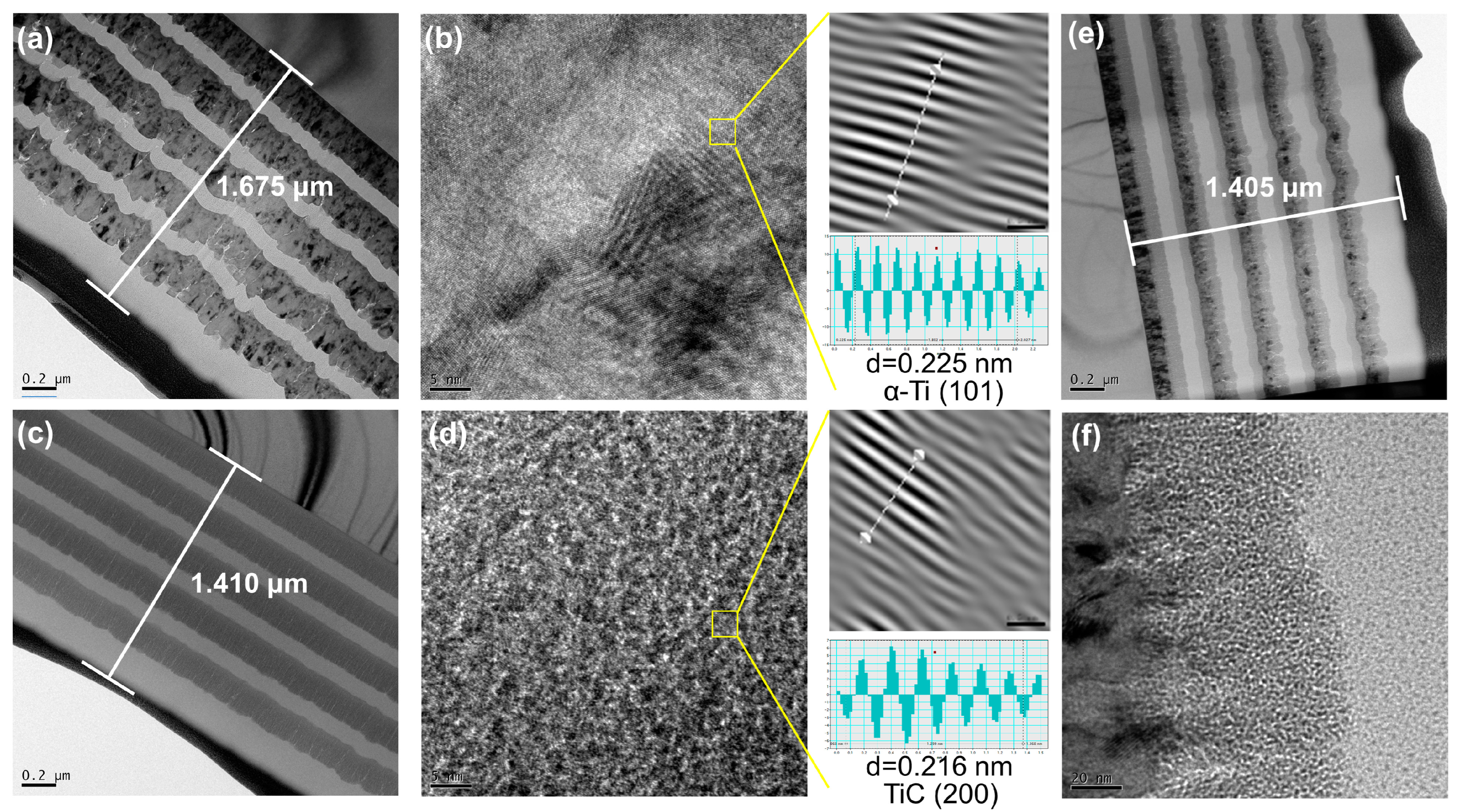
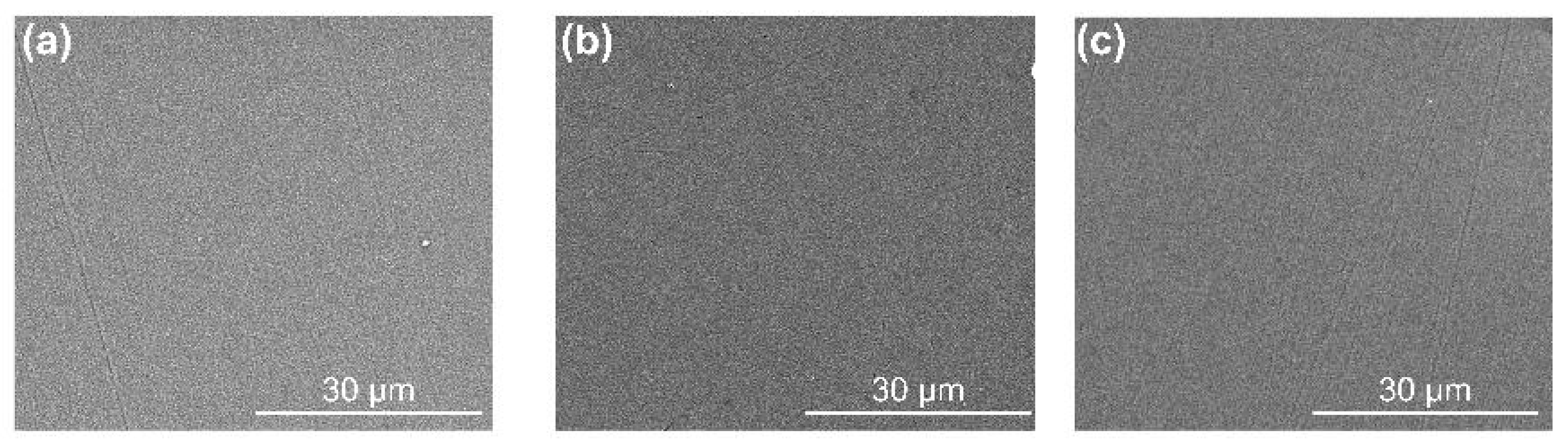
3.1. Microstructure Characterization

Figure 3 shows the surface SEM images of Ti/DLC, TiCx/DLC, and Ti-TiCx/DLC. All the coatings showed continuous, uniform, and smooth surfaces without visible defects. The roughness of the coatings decreased in the order of Ti/DLC, Ti-TiCx/DLC, and TiCx/DLC, which was mainly related to the different growth characteristics of the Ti layer and TiCx layer. The distribution of elements corresponding to each coating showed that the surface of the coatings was predominantly composed of carbon elements with a small amount of adsorbed oxygen. No signals for titanium were detected due to a thicker top a-C layer (200 nm) in the top layer, resulting in a weaker signal in the bottom layer.
Figure 4a,c,e portrays the TEM images showcasing the cross-sections of Ti/DLC, TiCx/DLC, and Ti-TiCx/DLC, respectively. The thickness of these three coatings ranged from 1.4 to 1.7 μm, presenting a clear multi-layered composition. In Figure 4b, an amplified perspective of the Ti layer and lattice spacing within Ti/DLC are revealed. It is evident that the Ti layer showed a crystalline arrangement with a lattice spacing measuring 0.225 nm. Compared to PDF cards, the predominant composition of the Ti layer appeared to be Ti (100). Turning to Figure 4d, a closer look at the TiC layer within TiCx/DLC featured a structure characterized by amorphous enclosed nanocrystals, exhibiting a lattice spacing of 0.216 nm. Comparative analysis with PDF cards indicated that the primary constituent of the TiC layer was Ti (200). Lastly, Figure 4e,f offers an enhanced view of the Ti-TiCx layer within Ti-TiCx/DLC. Notably, the method for preparing the Ti layer mirrored that of Ti/DLC, while the preparation of the TiC layer mirrored that of TiCx/DLC. Hence, the structural similarity between them remained apparent.
The atomic bond structure of the DLC coatings was characterized by visible Raman. Figure 5 shows the Raman spectra for clarity. After Gaussian fitting, the spectra could be decomposed into a D peak and a G peak, where the D peak centered at 1360 cm−1 originated from the breath mode of sp2 bonds and the G peak centered at 1560 cm−1 was due to the vibration mode of sp2 bonds in both rings and chains. The fitted peak position, peak area ratio ID/IG, and half maximum of G peak (FWHM) values are summarized in Table 1, which could reflect carbon atom disorder degrees, sp2/sp3 ratio, sp2 cluster size, and so on [33]. The fitting D peak, G peak, GFWHM, and ID/IG ratio kept stable around 1369 cm−1, 1548 cm−1, 180 cm−1, and 0.57, respectively, which revealed the same atomic bond structure of the top DLC layer.
Figure 6 shows the XPS C 1s core-level spectra and the fitted results of three kinds of multilayer coatings. The XPS C 1s spectra (inserts in Figure 6) were fitted into three dominant peaks approximately centered at 284.6 eV, 285.4 eV, and 286.6 eV, corresponding to sp2, sp3, and C-O/C=O hybridization, respectively [31,34,35,36]. The relative contents of sp3 and sp2-bonded carbon atoms were calculated from the peak area ratio. The sp2 and sp3 contents of the DLC coatings approximately remained at 39.5 ± 0.5% and 46.8 ± 0.5%, respectively, which agreed well with the Raman result above.

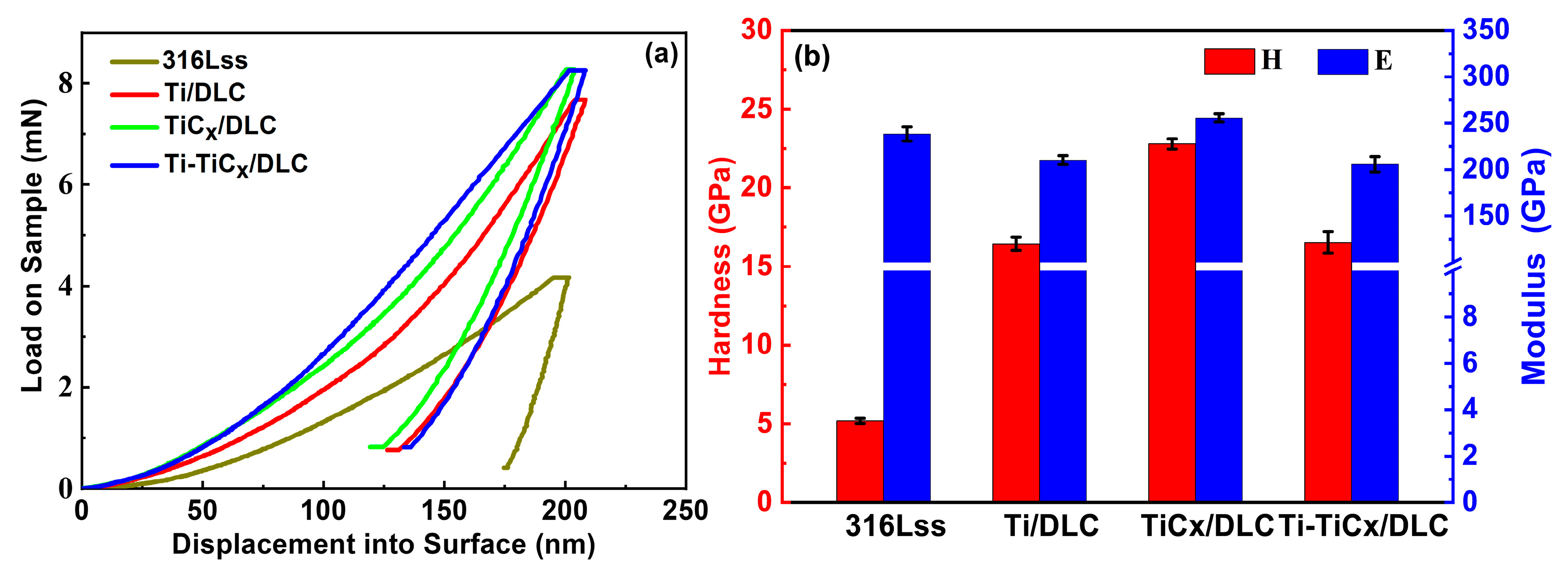
3.2. Mechanical Properties

Nanohardness (H) and elastic modulus (E) of substrates and three kinds of multilayer coatings were measured by the nanoindentation method, as shown in Figure 6. According to the nanoindentation load displacement curve in Figure 7a, the coated samples need a larger load than the substrates at the same indentation depth (200 nm), which reflected an improved hardness of the substrates, and the TiCx/DLC had the largest hardness around 22.8 GPa, as depicted in Figure 7b. As frequently mentioned, indexes in nanoindentation analysis, H/E and H3/E2, were regarded as key parameters reflecting the elastic–plastic deformation properties of materials, which were closely related to fracture toughness and wear resistance. Generally speaking, the higher values of H/E and H3/E2 mean the higher fracture toughness and wear resistance of the material [37,38,39,40,41,42,43,44]. The calculated H/E and H3/E2 of 316Lss and the three coatings are summarized in Table 2. Due to the excellent mechanical properties of the deposited DLC, all three coatings could improve the mechanical properties of the 316Lss effectively, and the TiCx/DLC coatings showed the highest fracture toughness and wear resistance. The hardness of Ti/DLC was the most minimal, followed by Ti-TiCx/DLC, which fell in the intermediate range, and ultimately, TiCx/DLC showed the highest level of hardness. This phenomenon may be attributed to the higher hardness of the intermediate layer of TiC in comparison to the Ti layer.

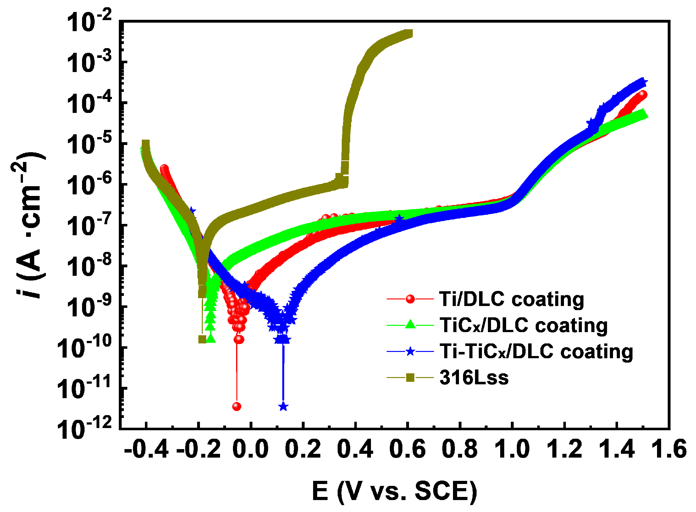
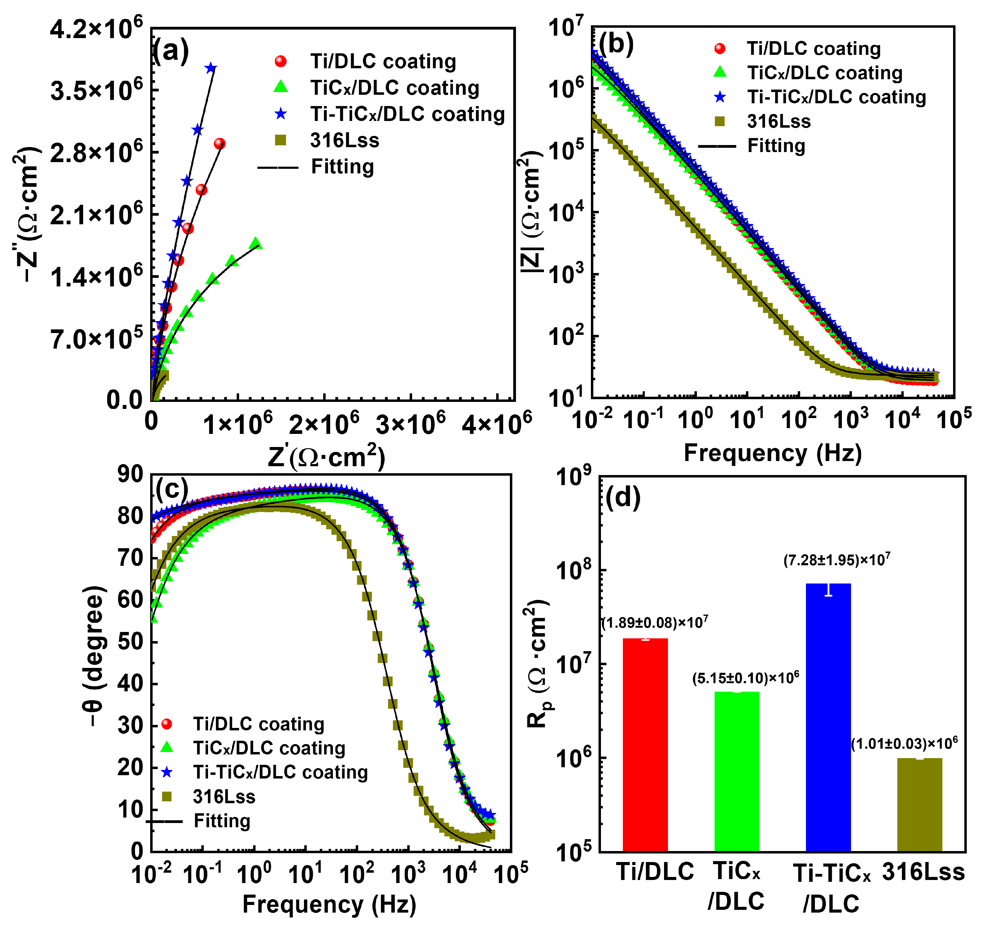
3.3. Corrosion Properties

Figure 8 and Table 3 show the potentiodynamic polarization curves and corresponding analysis results of bare 316Lss and coated samples in 3.5 wt.% NaCl. Potentiodynamic polarization curves of all coated samples had more positive corrosion potential (Ecorr), lower passivation current density (ipass), and higher pitting potential (Epit) compared with 316Lss, which inferred that all the DLC coatings improved the corrosion resistance of substrates significantly [45,46,47]. Especially, the pitting potential of 316Lss increased from 0.36 V to ~1.00 V, which indicated that the pitting resistance of 316Lss was greatly improved in 3.5 wt.% NaCl. In addition, the Ti-TiCx/DLC coatings displayed the largest positive Ecorr of 0.12 V and the lowest ipass of 5.68 × 10⁻¹⁰ A/cm2 among the three kinds of DLC coatings, which depicted their best corrosion resistance for 316Lss. The polarization resistance Rp of Ti-TiCx/DLC was around 5.83 × 10⁷ Ω·cm2, which was 2 times and 10 times higher than that of Ti/DLC and TiCx/DLC, respectively.
Figure 9 shows the EIS test results of bare substrate and coated 316Lss in 3.5 wt.% NaCl. Compared with bare 316Lss, all coated substrates depicted a larger capacitive arc, a higher low-frequency impedance, and a wider phase angle platform in the Nyquist and Bode diagram, as displayed in Figure 9a–c, which indicated that all the DLC coatings greatly improved the corrosion resistance of 316Lss [48,49]. Ti-TiCx/DLC had the largest capacitance–resistance arc radius, indicating a strong ability to hinder charge transfer. Ti-TiCx/DLC had a higher phase angle at low frequencies than other materials, representing better corrosion resistance stability and fewer defects. Among the three kinds of DLC coatings, Ti-TiCx/DLC exhibited the best corrosion resistance, while TiCx/DLC showed the worst performance.
The equivalent circuit was fitted to simulate the experimental EIS data, as shown in Figure 10. Since the corrosive solution would reach the coating/substrate interfaces through defects, which were formed during the preparation of the DLC coating, the equivalent circuit Rs (Cpore(Rpore(QdlRct))) displayed in Figure 10 was used [49,50,51,52]. Where Rs is the solution resistance between the sample and the reference electrode, Cpore and Rpore represent the capacitance and resistance of the coatings (or passivation coatings), and Qdl and Rct are the constant phase angle elements and charge transfer resistance of the double-layer capacitance, respectively [48,53].
Table 4 shows the equivalent circuit fitting results for each EIS. The fitting of the electronic equivalent circuit matched the experimental results well, as displayed in Figure 8, and the chi-square coefficient (χ2) was less than 10−3 orders of magnitude, indicating that the electronic equivalent circuit constant matched the EIS results. The charge transfer resistances (Rct) of Ti/DLC, TiCx/DLC, Ti-TiCx/DLC-coated 316Lss, and bare 316Lss substrates in 3.5 wt.% NaCl were 2.23 × 10⁷ Ω·cm2, 5.76 × 10⁶ Ω·cm2, 1.78 × 10⁸ Ω·cm2, and 1.19 × 10⁶ Ω·cm2, respectively (Figure 9d). As a result, the corrosion resistance of 316Lss in the 3.5 wt.% NaCl solution was greatly improved by the DLC coatings, especially the Rct of the 316Lss, which was increased by more than one order of magnitude by the Ti/DLC and Ti-TiCx/DLC coatings. The corrosion resistance of the TiCx/DLC coating was inferior when compared to the previous two samples. This was primarily due to the passivation effect of Ti, which effectively sealed off pores and prevented further corrosion of the substrate. In contrast, the passivation capacity of TiC was insufficient to achieve the same level of pore sealing as Ti.

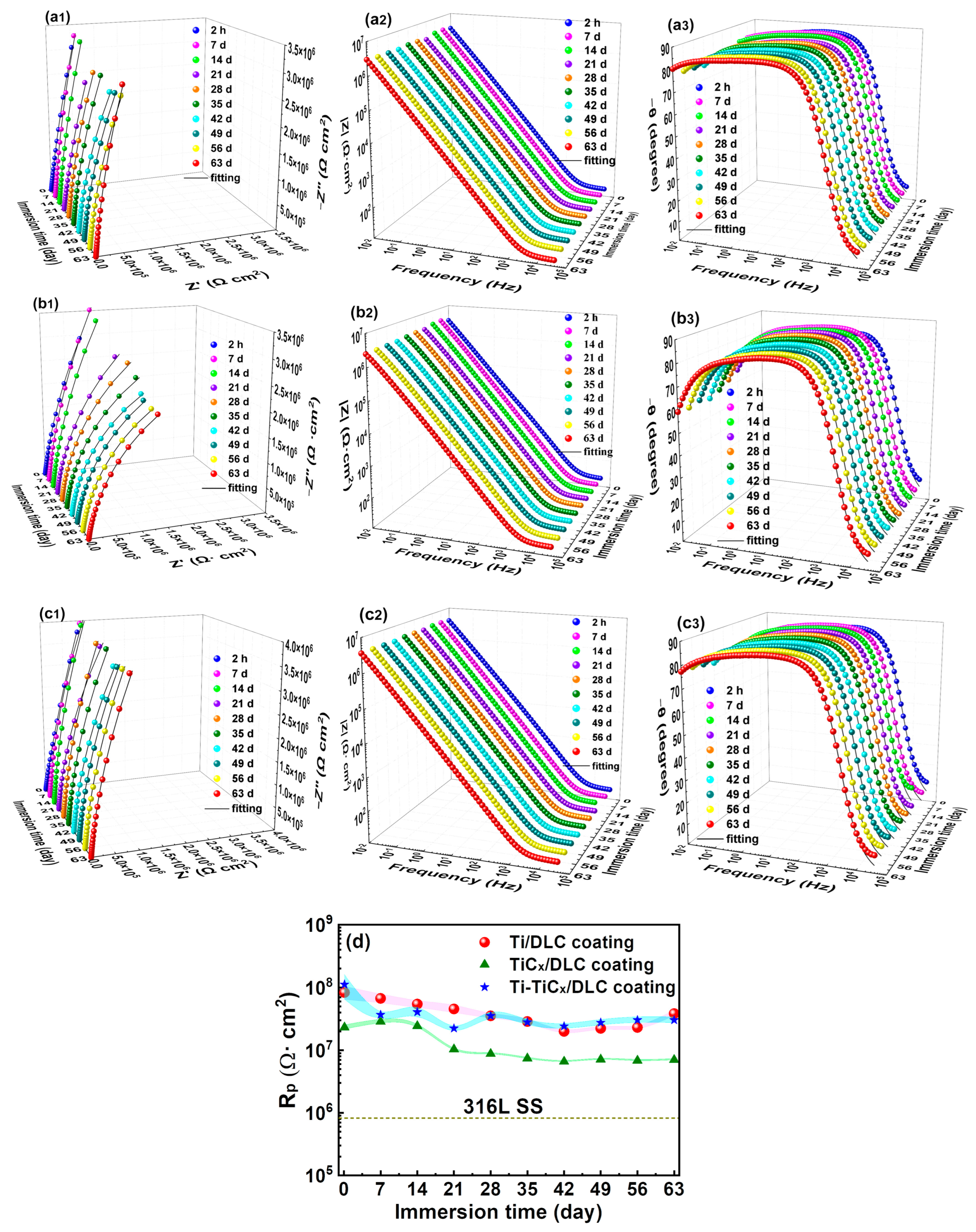
3.4. Electrochemical Corrosion Properties after Long-Term (63 Days) In-Situ Immersion

In order to investigate their long-term corrosion resistance, the EIS of the coated samples during 63 days of immersion in 3.5 wt.% NaCl was tested, as shown in Figure 11(a1–c1). At the beginning of the immersion (1–14 days) test, the polarization resistances of the three coated samples were similar; however, the polarization resistances of TiCx/DLC coatings decreased significantly after immersion for 21 days but were higher than those of 316Lss, as shown in Figure 11d, while the charge transfer resistances of Ti/DLC and Ti-TiCx/DLC coatings decreased slightly during the whole immersion period and remained at ~3.0 × 10⁷ Ω·cm2 after immersion for 28 days, which inferred that all the DLC coatings protected 316Lss substrates effectively. Furthermore, after 63 days of immersion, the polarization resistances of the coated samples were still much higher than those of 316Lss, which indicated that all the DLC coatings can provide good corrosion protection for the substrates under long-term immersion conditions.
Figure 12 exhibits the surface SEM images of the three coated samples after a long-term immersion test. Their surfaces did not change significantly compared with those before immersion (Figure 3), and no obvious corrosion trace was found, while a few local corrosion areas appeared on the surface of the Ti-TiCx/DLC coating after immersion, resulting in the exposure of the metallic substrate, as shown in Figure 13. EDS analysis showed that Fe, Cr, and O are mainly enriched in the corrosion pit, which is characteristic of corrosion products. This defect was a penetrating defect that exposed the substrate. The evolution of this defect unfolds as follows: initially, before deposition, there was an impurity particle on the surface of the coating that would not fall during the deposition process. Subsequently, the coating developed around the shape of the impurity, forming nodular-like defects. Following this, during the cooling process after deposition, the defect detached due to thermal stress. Ultimately, a defect exposing the substrate was formed [22]. Due to the growth mechanism of this defect, the multilayer interface structure cannot avoid the growth of penetrating defects. Penetrating defects became channels for corrosion fluids to pass through, rendering them pivotal sites in the corrosion failure of multilayer coatings [23].
Those corrosion spots mostly occurred where the defects existed (Figure 9), which was already reported for DLC coatings during immersion [54].

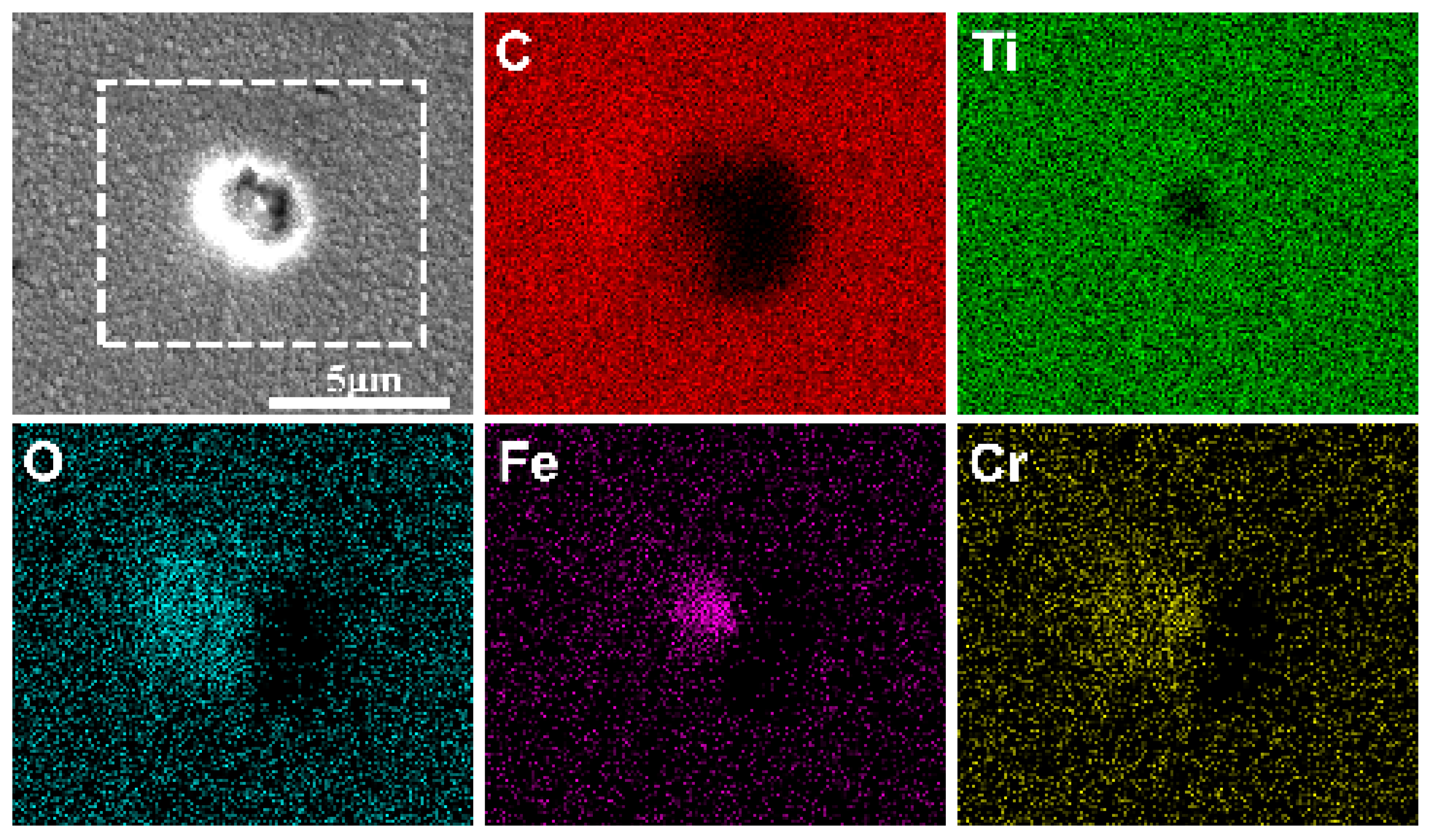
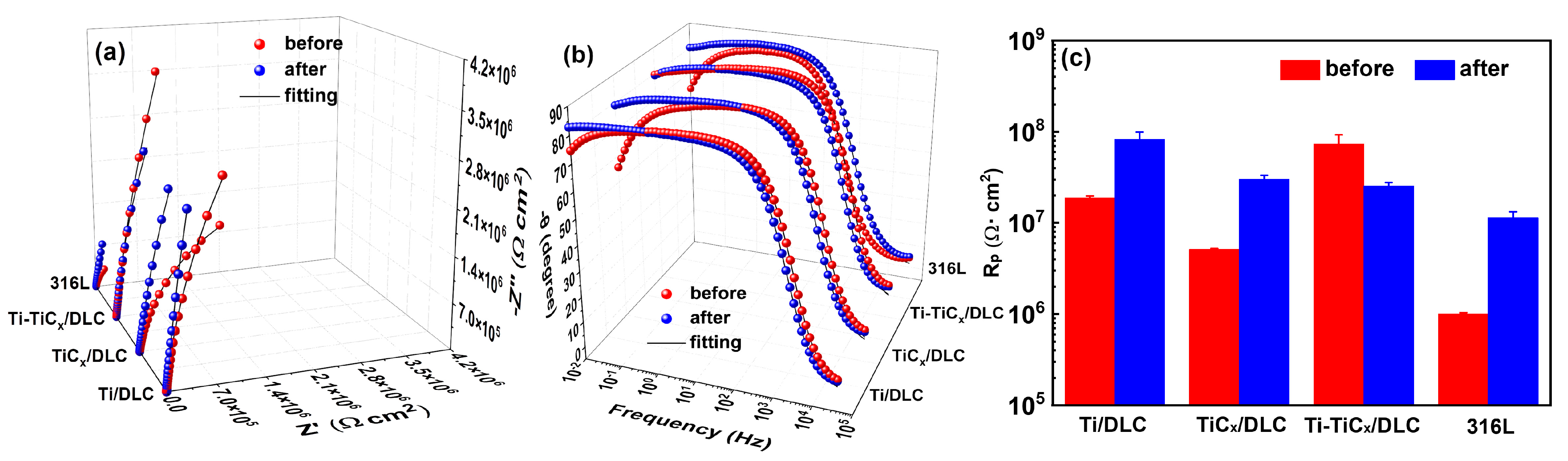
3.5. Electrochemical Corrosion Properties after a 3000 h Salt Spray Test

Figure 14 shows the photos of three kinds of multilayer coatings and 316Lss after a 3000 h neutral salt spray test [55]. There was no obvious corrosion trace in the center area of 316Lss and coated 316Lss samples, and a slight corrosion trace appeared around the border of the samples due to the edge effect [56]. Figure 15 displays their electrochemical impedance spectrum and polarization resistance in 3.5 wt.% NaCl before and after the 3000 h neutral salt spray test. After the salt spray test, both the capacitive arc and the polarization resistance of 316Lss increased significantly, since the thickening of the passivation coating on the 316Lss during the salt spray test can improve its corrosion resistance [46,47,57,58,59,60,61]. Similarly, the corrosion resistance of Ti/DLC and TiCx/DLC also showed a certain degree of improvement, which may be due to the fact that the insoluble corrosion products at the defects of the DLC coating can block the defects and slow down the subsequent corrosion in the environment of the salt spray test [62]. In Figure 15c, after the 3000 h neutral salt spray test, the charge transfer resistances of the coated samples were higher than those of 316Lss, which indicated that all the DLC coatings could also provide excellent long-term corrosion protection for 316Lss in a salt spray corrosion environment.

4. Discussion

According to the electrochemical test results, at the initial stage, Ti-TiCx/DLC coatings displayed the best corrosion resistance because the higher number of interfaces in the Ti-TiCx/DLC can hinder the penetration of the corrosive media [18].
During the long-term immersion in 3.5 wt.% NaCl, the EIS test showed the polarization resistance of TiCx/DLC coatings decreased significantly after 21 days of immersion, while that of Ti/DLC and Ti-TiCx/DLC only decreased slightly and kept stable at the high value of 3.0 × 10⁷ Ω·cm2 during the whole immersion period. Ti-TiCx/DLC coatings showed more interfaces, and the single layers on either side of the interface (Fe-Cr/Ti, Ti/TiCx, and TiCx/DLC) were similar in thermal expansion coefficient and mechanical properties, which may lead to its compact interface, resulting in fewer through-holes. Usually, the through-holes and defects in DLC coatings act as fast diffusion channels for corrosive ions, such as chloride ions, to trigger the electrochemical corrosion of 316Lss and more local corrosion spots.
Different from long-term immersion, after 3000 h of salt spray, the corrosion resistance of Ti/DLC and TiCx/DLC coatings increased to a certain extent. Generally, the insoluble corrosion products at the defects of the DLC coating can block the defects and slow down the subsequent corrosion in the environment of the salt spray test [62]. Therefore, the enrichment of corrosion products at the defects of the DLC coating is beneficial to improving its corrosion resistance in a salt spray corrosion environment, which is different from the corrosion process during the long-term immersion since the flow of the solution would prevent the accumulation of corrosion products at the defects of the DLC coatings [54].

5. Conclusions

Three kinds of multilayer DLC coatings, Ti/DLC, TiCx/DLC, and Ti-TiCx/DLC, were prepared on 316Lss by linear ion beam composite DC magnetron sputtering technology. Results demonstrated that the corrosion resistance of 316Lss in 3.5 wt.% NaCl was greatly improved by the three DLC coatings. Meanwhile, EIS in-situ monitoring (63 days) and neutral salt spray (3000 h) test results showed that all three DLC coatings could provide excellent long-term corrosion protection for 316Lss, and the more interfaces and insoluble corrosion products accounted for their improved corrosion resistance, respectively. Among the three DLC coatings, Ti-TiCx/DLC maintained excellent corrosion resistance (Rp ~3.0 × 10⁷ Ωcm2) during the 63-day long-term immersion due to the larger number of interfaces hindering the penetration of the corrosive media. The overall corrosion resistance of the coating was stable, but corrosion failure was observed at the defects. Defects were a key factor in coating failures. This study can provide a route to designing amorphous carbon protective coatings for long-term marine applications in different environments.

Author Contributions

Conceptualization, Methodology Investigation, Formal Analysis, Validation, Writing—Original, S.L.; Methodology Investigation, Formal Analysis, Validation, H.L.; Methodology Investigation, Validation, P.G.; Validation, X.L.; Validation, W.Y.; Validation, Funding Acquisition, G.M.; Formal Analysis, Funding Acquisition, K.N.; Formal Analysis, Funding Acquisition, P.K.; Writing—Review and Editing, Funding Acquisition, Supervision, A.W. All authors have read and agreed to the published version of the manuscript.

Funding

This work was financially supported by the State Key Project of Fundamental Research of China (2022YFB3808802), the National Science Fund for Distinguished Young Scholars of China (52025014), the National Natural Science Foundation of China (U20A20296), and the Natural Science Foundation of Ningbo (2022J305).

Institutional Review Board Statement

Not applicable.

Informed Consent Statement

Not applicable.

Data Availability Statement

Data are contained within the article.

Acknowledgments

Thank Linlin Liu for his contribution to this article.

Conflicts of Interest

The authors declare no conflicts of interest.

References

  1. Wood, R.J.K. Marine wear and tribocorrosion. Wear 2017, 376, 893–910. [Google Scholar] [CrossRef]
  2. Litwin, W.; Dymarski, C. Experimental research on water-lubricated marine stern tube bearings in conditions of improper lubrication and cooling causing rapid bush wear. Tribol. Int. 2016, 95, 449–455. [Google Scholar] [CrossRef]
  3. Han, W.; Chen, S.; Campbell, J.; Zhang, X.J.; Tang, Y.H. Fracture toughness and wear properties of nanosilica/epoxy composites under marine environment. Mater. Chem. Phys. 2016, 177, 147–155. [Google Scholar] [CrossRef]
  4. Biswas, P.V.; Ahn, J.H.; Lee, H.R. Monitoring of bearing wear in a marine engine by change of piston position—Effect of wear and inertia. Int. J. Precis. Eng. Manuf. 2013, 14, 1697–1701. [Google Scholar] [CrossRef]
  5. Li, Y.; Hu, T.; Li, Q.; Wu, Y.; Wang, L.; You, Y.; Wang, B.Y. Evaluation of the stress corrosion crack growth behaviour of high-strength marine steel based on model of crack tip mechano-electrochemical effect. J. Mater. Sci. Technol. 2024, 190, 93–105. [Google Scholar] [CrossRef]
  6. Liu, Z.; Chu, Z.H.; Chen, X.G.; Dong, Y.C.; Yang, Y.; Li, Y.Z.; Yan, D.R. Electrochemical impedance studies on tribocorrosion behavior of plasma-sprayed Al2O3 coatings. J. Therm. Spray Technol. 2015, 24, 878–884. [Google Scholar] [CrossRef]
  7. Xu, J.; Cai, L.X.; Lian, J.D.; Liao, Y.H. Corrosion-resistant behavior and structural optimization of Ti/Cr, Ti/Cu, Cr/Cu, Ti/Cr/Cu multimetallic layer coatings in simulated seawater. J. Phys. D-Appl. Phys. 2024, 57, 155501. [Google Scholar] [CrossRef]
  8. Zhang, S.L.; Huang, T.L.; Sun, S.D.; Wu, S.Z.; Yang, X.D.; Guo, F.; Zhang, B.; Dai, L.J. Effects of bias voltages on the tribological behaviors of DLC coatings. Coatings 2024, 14, 176. [Google Scholar] [CrossRef]
  9. Zhang, Y.P.; Wang, Q.; Ramachandran, C.S.; Guo, P.; Wang, A.Y. Microstructure andperformance of high-velocity oxygen-fuel coupled physical vapor deposition (HVOF-PVD) duplex protective coatings: A review. Coatings 2022, 12, 1395. [Google Scholar] [CrossRef]
  10. Sui, X.; Xu, R.; Liu, J.; Zhang, S.; Wu, Y.; Yang, J.; Hao, J. Tailoring the tribocorrosion and antifouling performance of (Cr, Cu)-GLC coatings for marine application. ACS Appl. Mater. Interfaces 2018, 10, 36531–36539. [Google Scholar] [CrossRef]
  11. Azzi, M.; Paquette, M.; Szpunar, J.A.; Klemberg-Sapieha, J.E.; Martinu, L. Tribocorrosion behaviour of DLC-coated 316L stainless steel. Wear 2009, 267, 860–866. [Google Scholar] [CrossRef]
  12. Kim, J.G.; Lee, K.R.; Yang, S.J. Wear-corrosion performance of Si-DLC coatings on Ti-6Al-4V substrate. J. Biomed. Mater. Res. Part A 2008, 86, 41–47. [Google Scholar] [CrossRef] [PubMed]
  13. Cui, C.Q.; Yang, C.Y. Enhanced Wear and Corrosion Resistance of AZ91 Magnesium Alloy via Adherent Si-DLC Coating with Si-Interlayer: Impact of Biasing Voltage. Coatings 2024, 14, 341. [Google Scholar] [CrossRef]
  14. Liu, Z.Y.; Yin, P.M.; Mou, C.L.; Cao, X.Q.; Zhang, G.A.; Xue, Q.J. Corrosion behavior of Si-DLC film in simulant solutions containing CO2-H2S-Cl. Surf. Coat. Technol. 2024, 478, 130455. [Google Scholar] [CrossRef]
  15. Vicen, M.; Kajánek, D.; Trsko, L.; Bokuvka, O.; Buchtík, M.; Florková, Z.; Frkán, M. Improving of 100Cr6 steel corrosion and wear properties in simulated sea water environment by Tungsten-Doped DLC coating. Materials 2023, 16, 4334. [Google Scholar] [CrossRef] [PubMed]
  16. Chen, Z.; Du, N.Z.; Li, X.W.; Wei, X.B.; Ding, J.Q.; Lu, S.Q.; Du, S.J.; Feng, C.A.; Chen, K.; Zhang, D.K.; et al. Atomic-scale understanding on the tribological behavior of amorphous carbon films under different contact pressures and surface textured shapes. Materials 2023, 16, 6108. [Google Scholar] [CrossRef] [PubMed]
  17. Totolin, V.; Pejaković, V.; Csanyi, T.; Hekele, O.; Huber, M.; Rodríguez Ripoll, M. Surface engineering of Ti6Al4V surfaces for enhanced tribocorrosion performance in artificial seawater. Mater. Des. 2016, 104, 10–18. [Google Scholar] [CrossRef]
  18. Wei, J.; Li, H.; Liu, L.; Guo, P.; Ke, P.; Wang, A. Enhanced tribological and corrosion properties of multilayer ta-C films via alternating sp3 content. Surf. Coat. Technol. 2019, 374, 317–326. [Google Scholar] [CrossRef]
  19. Li, L.; Liu, L.L.; Li, X.; Guo, P.; Ke, P.; Wang, A. Enhanced tribocorrosion performance of Cr/GLC multilayered films for marine protective application. ACS Appl. Mater. Interfaces 2018, 10, 13187–13198. [Google Scholar] [CrossRef]
  20. Maguire, P.D.; McLaughlin, J.A.; Okpalugo, T.I.T.; Lemoine, P.; Papakonstantinou, P.; McAdams, E.T.; Needham, M.; Ogwu, A.A.; Ball, M.; Abbas, G.A. Mechanical stability, corrosion performance and bioresponse of amorphous diamond-like carbon for medical stents and guidewires. Diam. Relat. Mater. 2005, 14, 1277–1288. [Google Scholar] [CrossRef]
  21. Turcio-Ortega, D.; Rodil, S.E.; Muhl, S. Corrosion behavior of amorphous carbon deposit in 0.89% NaCl by electrochemical impedance spectroscopy. Diam. Relat. Mater. 2009, 18, 1360–1368. [Google Scholar] [CrossRef]
  22. Liu, Y.; Li, S.; Li, H.; Ma, G.; Sun, L.; Guo, P.; Ke, P.; Lee, K.-R.; Wang, A. Controllable defect engineering to enhance the corrosion resistance of Cr/GLC multilayered coating for deep-sea applications. Corros. Sci. 2022, 199, 110175. [Google Scholar] [CrossRef]
  23. Liu, Y.; Du, H.; Zuo, X.; Guo, P.; Liu, L.; Lee, K.-R.; Wang, A.; Ke, P. Cr/GLC multilayered coating in simulated deep-sea environment: Corrosion behavior and growth defect evolution. Corros. Sci. 2021, 188, 109528. [Google Scholar] [CrossRef]
  24. Li, H.; Guo, P.; Zhang, D.; Liu, L.; Wang, Z.; Ma, G.; Xin, Y.; Ke, P.; Saito, H.; Wang, A. Interface-induced degradation of amorphous carbon films/stainless steel bipolar plates in proton exchange membrane fuel cells. J. Power Sources 2020, 469, 228269. [Google Scholar] [CrossRef]
  25. Li, H.; Liu, L.; Guo, P.; Sun, L.; Wei, J.; Liu, Y.; Li, S.; Wang, S.; Lee, K.-R.; Ke, P.; et al. Long-term tribocorrosion resistance and failure tolerance of multilayer carbon-based coatings. Friction 2022, 10, 1707–1721. [Google Scholar] [CrossRef]
  26. Xu, Z.Y.; Sun, H.; Leng, Y.X.; Li, X.Y.; Yang, W.M.; Huang, N. Effect of modulation periods on the microstructure and mechanical properties of DLC/TiC multilayer films deposited by filtered cathodic vacuum arc method. Appl. Surf. Sci. 2015, 328, 319–324. [Google Scholar] [CrossRef]
  27. Ipaz, L.; Caicedo, J.C.; Esteve, J.; Espinoza-Beltran, F.J.; Zambrano, G. Improvement of mechanical and tribological properties in steel surfaces by using titanium–aluminum/titanium–aluminum nitride multilayered system. Appl. Surf. Sci. 2012, 258, 3805–3814. [Google Scholar] [CrossRef]
  28. Li, C.L.; Wu, F.B.; Lee, J.W.; Tsai, Y.Z.; Chang, L.C. Characteristics of Cr2N/Cu multilayered thin films with different bilayer thickness. Surf. Coat. Technol. 2009, 204, 941–946. [Google Scholar] [CrossRef]
  29. Cheng, F.; Wu, F.; Liu, L.; Yang, S.; Ji, W. Investigation on cavitation erosion of diamond-like carbon films with heterogeneous multilayer structure. Surf. Coat. Technol. 2021, 405, 126682. [Google Scholar] [CrossRef]
  30. Taki, Y.; Takai, O. XPS structural characterization of hydrogenated amorphous carbon thin films prepared by shielded arc ion plating. Thin Solid Film. 1998, 316, 45–50. [Google Scholar] [CrossRef]
  31. Merel, P.; Tabbal, M.; Chaker, M.; Moisa, S.; Margot, J. Direct evaluation of the sp(3) content in diamond-like-carbon films by XPS. Appl. Surf. Sci. 1998, 136, 105–110. [Google Scholar] [CrossRef]
  32. Diaz, J.; Paolicelli, G.; Ferrer, S.; Comin, F. Separation of the sp3 and sp2 components in the C1s photoemission spectra of amorphous carbon films. Phys. Rev. B 1996, 54, 8064–8069. [Google Scholar] [CrossRef] [PubMed]
  33. Chu, P.K.; Li, L.H. Characterization of amorphous and nanocrystalline carbon films. Mater. Chem. Phys. 2006, 96, 253–277. [Google Scholar] [CrossRef]
  34. Mohagheghpour, E.; Rajabi, M.; Gholamipour, R.; Larijani, M.M.; Sheibani, S. Correlation study of structural, optical and electrical properties of amorphous carbon thin films prepared by ion beam sputtering deposition technique. Appl. Surf. Sci. 2016, 360, 52–58. [Google Scholar] [CrossRef]
  35. Guo, P.; Li, X.W.; Sun, L.L.; Chen, R.D.; Ke, P.L.; Wang, A.Y. Stress reduction mechanism of diamond-like carbon films incorporated with different Cu contents. Thin Solid Film. 2017, 640, 45–51. [Google Scholar] [CrossRef]
  36. Nakao, S.; Yukimura, K.; Nakano, S.; Ogiso, H. DLC Coating by HiPIMS: The Influence of Substrate Bias Voltage. IEEE Trans. Plasma Sci. 2013, 41, 1819–1829. [Google Scholar] [CrossRef]
  37. Chen, X.J.; Du, Y.; Chung, Y.W. Commentary on using H/E and H3/E2 as proxies for fracture toughness of hard coatings. Thin Solid Films 2019, 688, 137265. [Google Scholar] [CrossRef]
  38. Zhang, S.D.; Yan, M.F.; Yang, Y.; Zhang, Y.X.; Yan, F.Y.; Li, H.T. Excellent mechanical, tribological and anti-corrosive performance of novel Ti-DLC nanocomposite thin films prepared via magnetron sputtering method. Carbon 2019, 151, 136–147. [Google Scholar] [CrossRef]
  39. Ren, P.; Wen, M.; Zhang, K.; Du, S.; Zhang, Y.; Chen, J.; Zheng, W. Self-assembly of TaC@Ta core–shell-like nanocomposite film via solid-state dewetting: Toward superior wear and corrosion resistance. Acta Mater. 2018, 160, 72–84. [Google Scholar] [CrossRef]
  40. Yang, Y.; Yan, M.F.; Zhang, Y.X.; Li, D.Y.; Zhang, C.S.; Zhu, Y.D.; Wang, Y.X. Catalytic growth of diamond-like carbon on Fe3C-containing carburized layer through a single-step plasma-assisted carburizing process. Carbon 2017, 122, 1–8. [Google Scholar] [CrossRef]
  41. Li, L.; Bai, W.; Wang, X.; Gu, C.; Jin, G.; Tu, J. Mechanical properties and in vitro and in vivo biocompatibility of a-C/a-C:Ti nanomultilayer films on Ti6Al4V Alloy as medical implants. ACS Appl. Mater. Interfaces 2017, 9, 15933–15942. [Google Scholar] [CrossRef] [PubMed]
  42. Ren, P.; Zhang, K.; He, X.; Du, S.X.; Yang, X.Y.; An, T.; Wen, M.; Zheng, W.T. Toughness enhancement and tribochemistry of the Nb-Ag-N films actuated by solute Ag. Acta Mater. 2017, 137, 1–11. [Google Scholar] [CrossRef]
  43. Mockute, A.; Palisaitis, J.; Alling, B.; Berastegui, P.; Broitman, E.; Naslund, L.A.; Nedfors, N.; Lu, J.; Jensen, J.; Hultman, L.; et al. Age hardening in (Ti1-xAlx) B2+Δ thin films. Scr. Mater. 2017, 127, 122–126. [Google Scholar] [CrossRef]
  44. Lin, J.; Wei, R.; Bitsis, D.C.; Lee, P.M. Development and evaluation of low friction TiSiCN nanocomposite coatings for piston ring applications. Surf. Coat. Technol. 2016, 298, 121–131. [Google Scholar] [CrossRef]
  45. Habibi, M.; Javadi, S.; Ghoranneviss, M. Investigation on the structural properties and corrosion inhibition of W coatings on stainless steel AISI 304 using PF device. Surf. Coat. Technol. 2014, 254, 112–120. [Google Scholar] [CrossRef]
  46. Choi, H.S.; Park, B.; Lee, J.J. CrB2 coatings deposited by inductively coupled plasma assisted DC magnetron sputtering. Surf. Coat. Technol. 2007, 202, 982–986. [Google Scholar] [CrossRef]
  47. Audronis, M.; Kelly, P.J.; Arnell, R.D.; Leyland, A.; Matthews, A. The structure and properties of chromium diboride coatings deposited by pulsed magnetron sputtering of powder targets. Surf. Coat. Technol. 2005, 200, 1366–1371. [Google Scholar] [CrossRef]
  48. Liu, C.; Bi, Q.; Leyland, A.; Matthews, A. An electrochemical impedance spectroscopy study of the corrosion behaviour of PVD coated steels in 0.5 N NaCl aqueous solution: Part II. EIS interpretation of corrosion behaviour. Corros. Sci. 2003, 45, 1257–1273. [Google Scholar] [CrossRef]
  49. Ahn, S.H.; Lee, J.H.; Kim, H.G.; Kim, J.G. A study on the quantitative determination of through-coating porosity in PVD-grown coatings. Appl. Surf. Sci. 2004, 233, 105–114. [Google Scholar] [CrossRef]
  50. Wu, H.; Xiao, S.; Chen, D.L.; Qasim, A.M.; Ding, K.J.; Wu, G.S.; Chu, P.K. Effects of diamond-like carbon film on the corrosion behavior of NdFeB permanent magnet. Surf. Coat. Technol. 2017, 312, 66–74. [Google Scholar] [CrossRef]
  51. Shanaghi, A.; Rouhaghdam, A.R.S.; Ahangarani, S.; Chu, P.K.; Farahani, T.S. Effects of duty cycle on microstructure and corrosion behavior of TiC coatings prepared by DC pulsed plasma CVD. Appl. Surf. Sci. 2012, 258, 3051–3057. [Google Scholar] [CrossRef]
  52. Zeng, A.; Liu, E.; Annergren, I.F.; Tan, S.N.; Zhang, S.; Hing, R.; Gao, J. EIS capacitance diagnosis of nanoporosity effect on the corrosion protection of DLC films. Diam. Relat. Mater. 2002, 11, 160–168. [Google Scholar] [CrossRef]
  53. Grips, V.K.W.; Selvi, V.E.; Barshilia, H.C.; Rajam, K.S. Effect of electroless nickel interlayer on the electrochemical behavior of single layer CrN, TiN, TiAlN coatings and nanolayered TiAlN/CrN multilayer coatings prepared by reactive dc magnetron sputtering. Electrochim. Acta 2006, 51, 3461–3468. [Google Scholar] [CrossRef]
  54. Manninen, N.K.; Calderon, S.; Carvalho, I.; Henriques, M.; Cavaleiro, A.; Carvalho, S. Antibacterial Ag/a-C nanocomposite coatings: The influence of nano-galvanic a-C and Ag couples on Ag ionization rates. Appl. Surf. Sci. 2016, 377, 283–291. [Google Scholar] [CrossRef]
  55. ASTM B117-2016; Standard Practice for Operating Salt Spray (Fog) apparatus. ASTM International: West Conshohocken, PA, USA, 2018.
  56. Trinh, D.; Dauphin Ducharme, P.; Mengesha Tefashe, U.; Kish, J.R.; Mauzeroll, J. Influence of edge effects on local corrosion rate of magnesium alloy/mild steel galvanic couple. Anal. Chem. 2012, 84, 9899–9906. [Google Scholar] [CrossRef]
  57. Guimaraes, M.C.R.; de Castilho, B.C.N.M.; Nossa, T.D.; Avila, P.R.T.; Cucatti, S.; Alvarez, F.; Garcia, J.L.; Pinto, H.C. On the effect of substrate oscillation on CrN coatings deposited by HiPIMS and dcMS. Surf. Coat. Technol. 2018, 340, 112–120. [Google Scholar] [CrossRef]
  58. Viswanathan, S.; Mohan, L.; Bera, P.; Kumar, V.P.; Barshilia, H.C.; Anandan, C. Corrosion and wear behaviors of Cr-Doped diamond-like carbon coatings. J. Mater. Eng. Perform. 2017, 26, 3633–3647. [Google Scholar] [CrossRef]
  59. Shukla, K.; Rane, R.; Alphonsa, J.; Maity, P.; Mukherjee, S. Structural, mechanical and corrosion resistance properties of Ti/TiN bilayers deposited by magnetron sputtering on AISI 316L. Surf. Coat. Technol. 2017, 324, 167–174. [Google Scholar] [CrossRef]
  60. Bai, W.Q.; Xie, Y.J.; Li, L.L.; Wang, X.L.; Gu, C.D.; Tu, J.P. Tribological and corrosion behaviors of Zr-doped graphite-like carbon nanostructured coatings on Ti6Al4V alloy. Surf. Coat. Technol. 2017, 320, 235–239. [Google Scholar] [CrossRef]
  61. Lin, J.L.; Wang, B.; Ou, Y.X.; Sproul, W.D.; Dahan, I.; Moore, J.J. Structure and properties of CrSiN nanocomposite coatings deposited by hybrid modulated pulsed power and pulsed dc magnetron sputtering. Surf. Coat. Technol. 2013, 216, 251–258. [Google Scholar] [CrossRef]
  62. Mischler, S. Triboelectrochemical techniques and interpretation methods in tribocorrosion: A comparative evaluation. Tribol. Int. 2008, 41, 573–583. [Google Scholar] [CrossRef]
Figure 1. The structure of (a) Ti/DLC, (b) TiCx/DLC, and (c) Ti-TiCx/DLC multilayer coatings.
Materials 17 02129 g001
Figure 2. Schematic diagram of the hybrid deposition system.
Materials 17 02129 g002
Figure 3. The surface SEM images and EDS of (a) Ti/DLC, (b) TiCx/DLC, and (c) Ti-TiCx/DLC multilayer coatings (C is carbon; O is oxygen).
Materials 17 02129 g003
Figure 4. The cross-section TEM images of (a) Ti/DLC, (b) the enlarged view of Ti/DLC, (c) TiCx/DLC, (d) the enlarged view of TiCx/DLC, (e) Ti-TiCx/DLC, and (f) the enlarged view of Ti-TiCx/DLC.
Materials 17 02129 g004
Figure 5. Raman spectra of three kinds of multilayer coatings (The orange background color represents the D peak, while the purple background color represents the G peak).
Materials 17 02129 g005
Figure 6. The sp3 and sp2 contents of three kinds of multilayer coatings. The inset shows the XPS C 1s core-level spectra (The orange background color represents the sp2 peak, while the purple background color represents the sp3 peak).
Materials 17 02129 g006
Figure 7. (a) Load indentation depth curves; (b) hardness and elastic modulus of substrates and three kinds of multilayer coatings.
Materials 17 02129 g007
Figure 8. Potentiodynamic polarization curves of three kinds of multilayer coatings and 316Lss in 3.5 wt.% NaCl.
Materials 17 02129 g008
Figure 9. (a) Nyquist diagram, (b,c) Bode diagram, and (d) charge transfer resistances of Ti/DLC, TiCx/DLC, and Ti-TiCx/DLC multilayer coatings and 316Lss in 3.5 wt.% NaCl.
Materials 17 02129 g009
Figure 10. Electronic equivalent circuits employed to simulate the experimental EIS data.
Materials 17 02129 g010
Figure 11. (a1c3) EIS and (d) charge transfer resistance curves of three kinds of multilayer coatings and 316Lss in 3.5 wt.% NaCl.
Materials 17 02129 g011
Figure 12. The surface SEM images of (a) Ti/DLC, (b) TiCx/DLC, and (c) Ti-TiCx/DLC after immersion in 3.5 wt.% NaCl for 63 days.
Materials 17 02129 g012
Figure 13. The typical local corrosion area on the Ti-TiCx/DLC coatings after immersion in 3.5 wt.% NaCl for 63 days and the corresponding EDS analysis results (EDS corresponds to the result in the white dotted box).
Materials 17 02129 g013
Figure 14. Photos of three kinds of coated samples and 316Lss after the 3000 h neutral salt spray test.
Materials 17 02129 g014
Figure 15. (a) Nyquist diagram, (b) Bode diagram, and (c) charge transfer resistances of three coated samples and 316Lss in 3.5 wt.% NaCl before and after the 3000 h neutral salt spray test.
Materials 17 02129 g015
Table 1. Raman fitting results of three kinds of multilayer coatings.
SampleD Peak (cm−1)G Peak (cm−1)GFWHM (cm−1)ID/IG
Ti/DLC1368.041545.73181.140.56
TiCx/DLC1369.251552.84181.730.59
Ti-TiCx/DLC1369.801547.26179.950.56
Table 2. Mechanical properties of substrates and three kinds of multilayer coatings.
SampleH (GPa)E (GPa)H/EH3/E2 (GPa)
316Lss5.18 ± 0.16238.46 ± 7.640.0220.0024
Ti/DLC16.44 ± 0.42210.37 ± 4.920.0780.1004
TiCx/DLC22.79 ± 0.33255.78 ± 4.570.0890.1809
Ti-TiCx/DLC16.53 ± 0.68205.78 ± 8.370.0800.1067
Table 3. Analysis results of the potentiodynamic polarization test in 3.5 wt.% NaCl.
SampleTi/DLCTiCx/DLCTi-TiCx/DLC316Lss
Ecorr (V)−0.05−0.150.12−0.19
ipass (A/cm2)1.12 × 10−94.27 × 10−95.68 × 10−101.86 × 10⁻⁸
βa (mV/decade)135.00177.70110.7061.00
βc (mV/decade)87.9266.99244.5046.15
Rp (Ω·cm2)2.06 × 1074.95 × 1065.83 × 1076.13 × 105
Epit (V)~1.01~0.98~1.00~0.36
Table 4. EIS fitting results of three kinds of multilayer coatings and 316Lss in 3.5 wt.% NaCl.
SampleTi/DLCTiCx/DLCTi-TiCx/DLC316Lss
Rs (Ω·cm2)18.6220.2523.722.27
Cpore (F·cm−2)4.00 × 10−63.87 × 10−63.05 × 10−63.24 × 10−5
Rpore (Ω·cm2)547,82062,590515,040103,820
Qdl−1·cm−2·sn)3.43 × 10−78.255 × 10−73.83 × 10−72.48 × 10−6
ndl0.6510.6390.650.50
Rct (Ω·cm2)2.23 × 1075.76 × 1061.78 × 1081.19 × 106
χ23.22 × 10−42.82 × 10−49.37 × 10−44.94 × 10−4
Disclaimer/Publisher’s Note: The statements, opinions and data contained in all publications are solely those of the individual author(s) and contributor(s) and not of MDPI and/or the editor(s). MDPI and/or the editor(s) disclaim responsibility for any injury to people or property resulting from any ideas, methods, instructions or products referred to in the content.

