
Study of CFRP Laminate Gradually Modified throughout the Thickness Using Thin Ply under Transvers Tensile Loading
 ,
, 
Abstract
:1. Introduction
2. Experimental Study
2.1. Materials
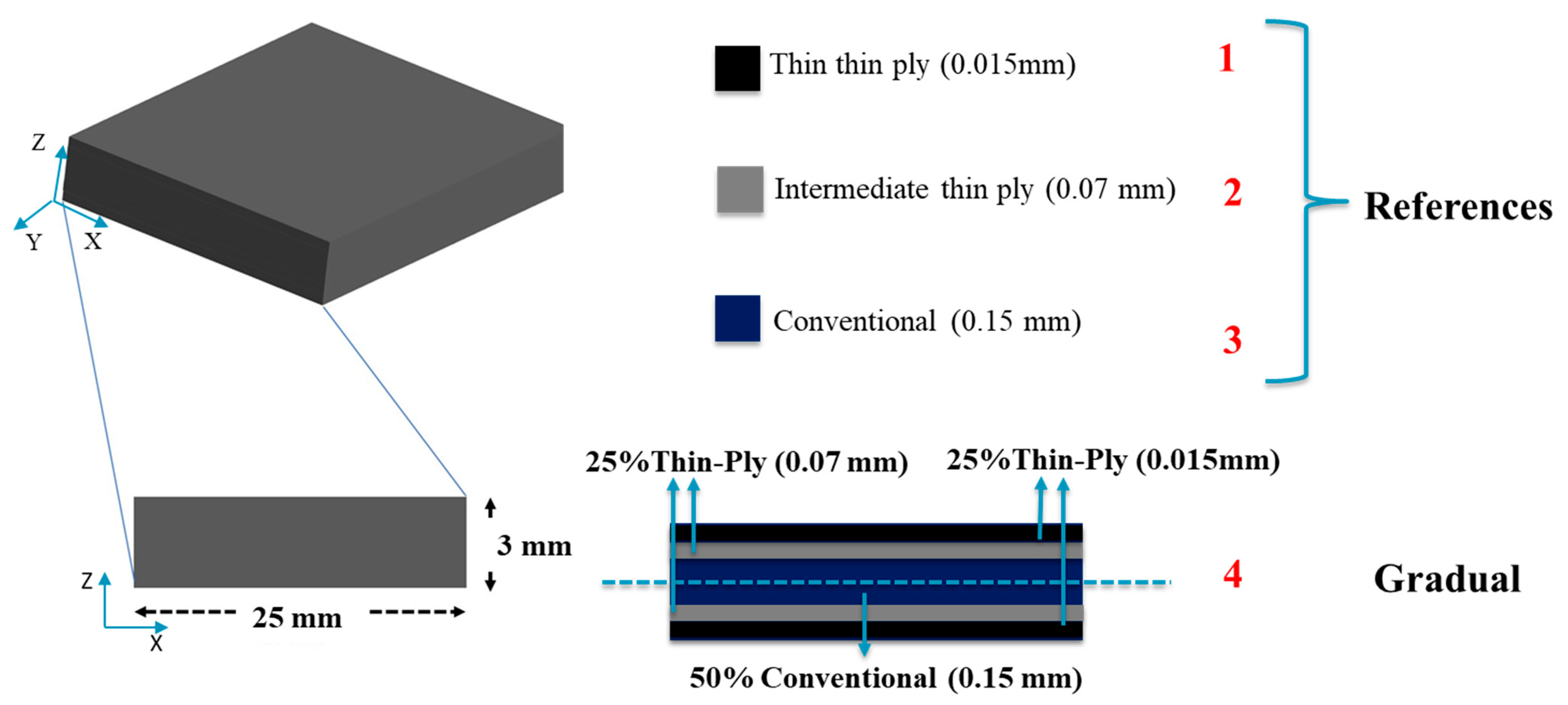
2.2. Configurations
2.3. Manufacturing Process
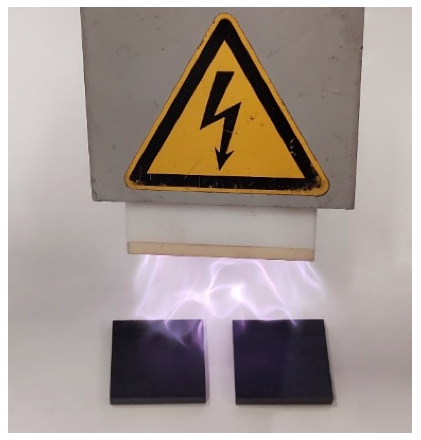
2.4. Surface Treatment
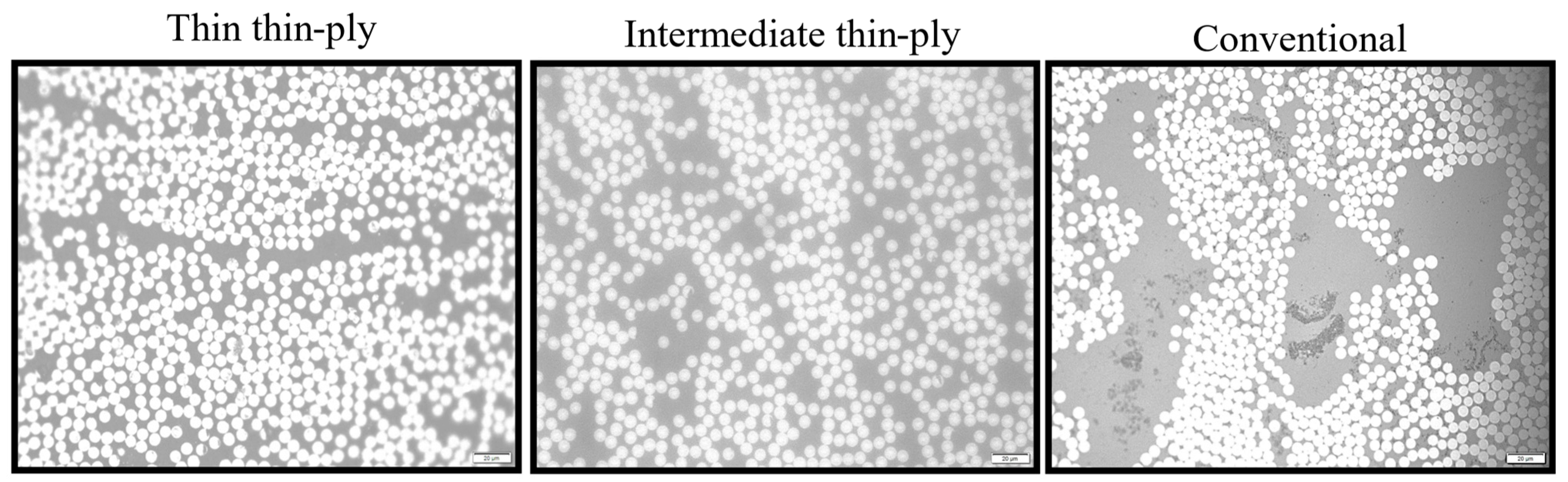
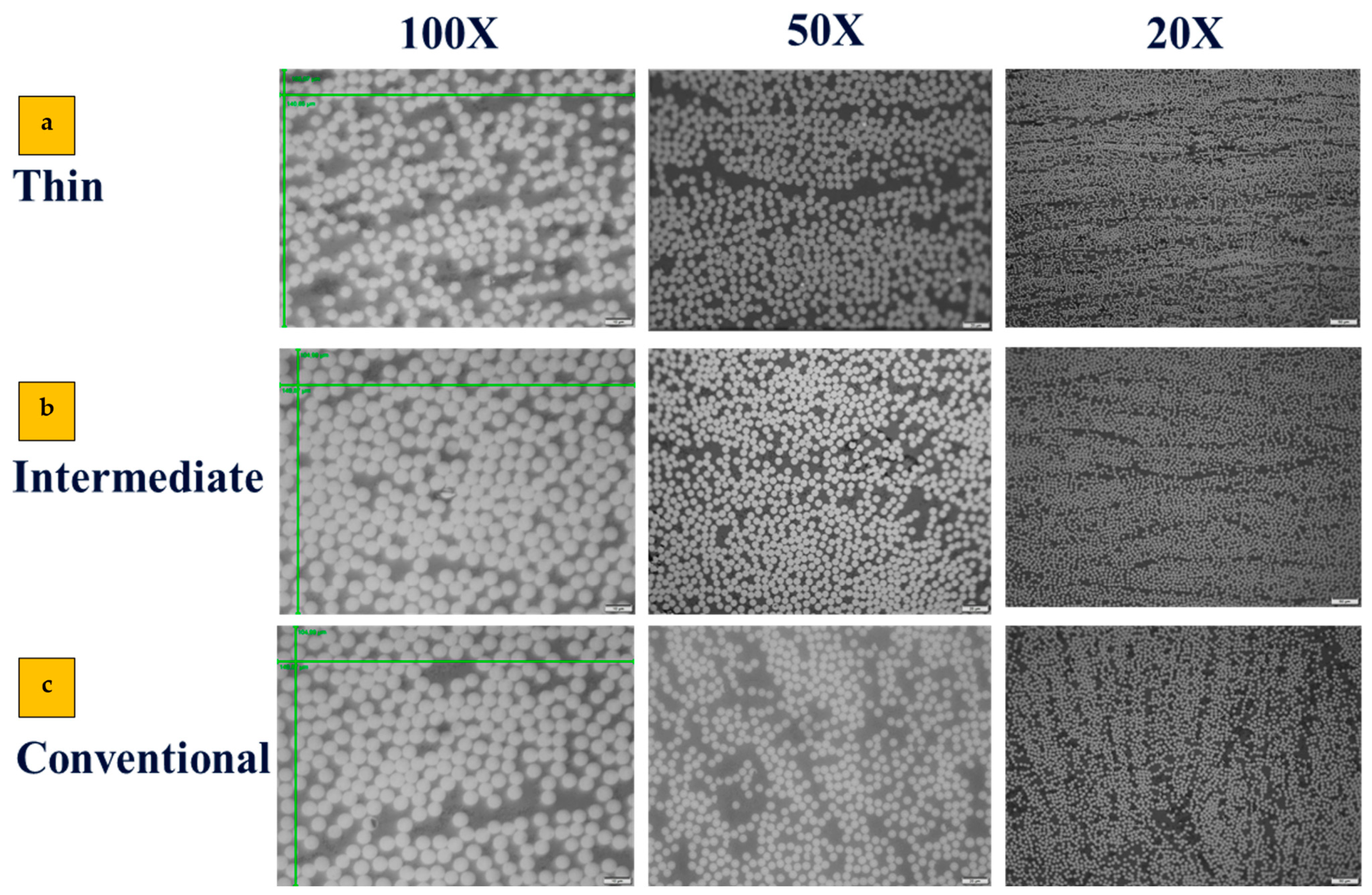
2.5. Scanning Optical Microscope
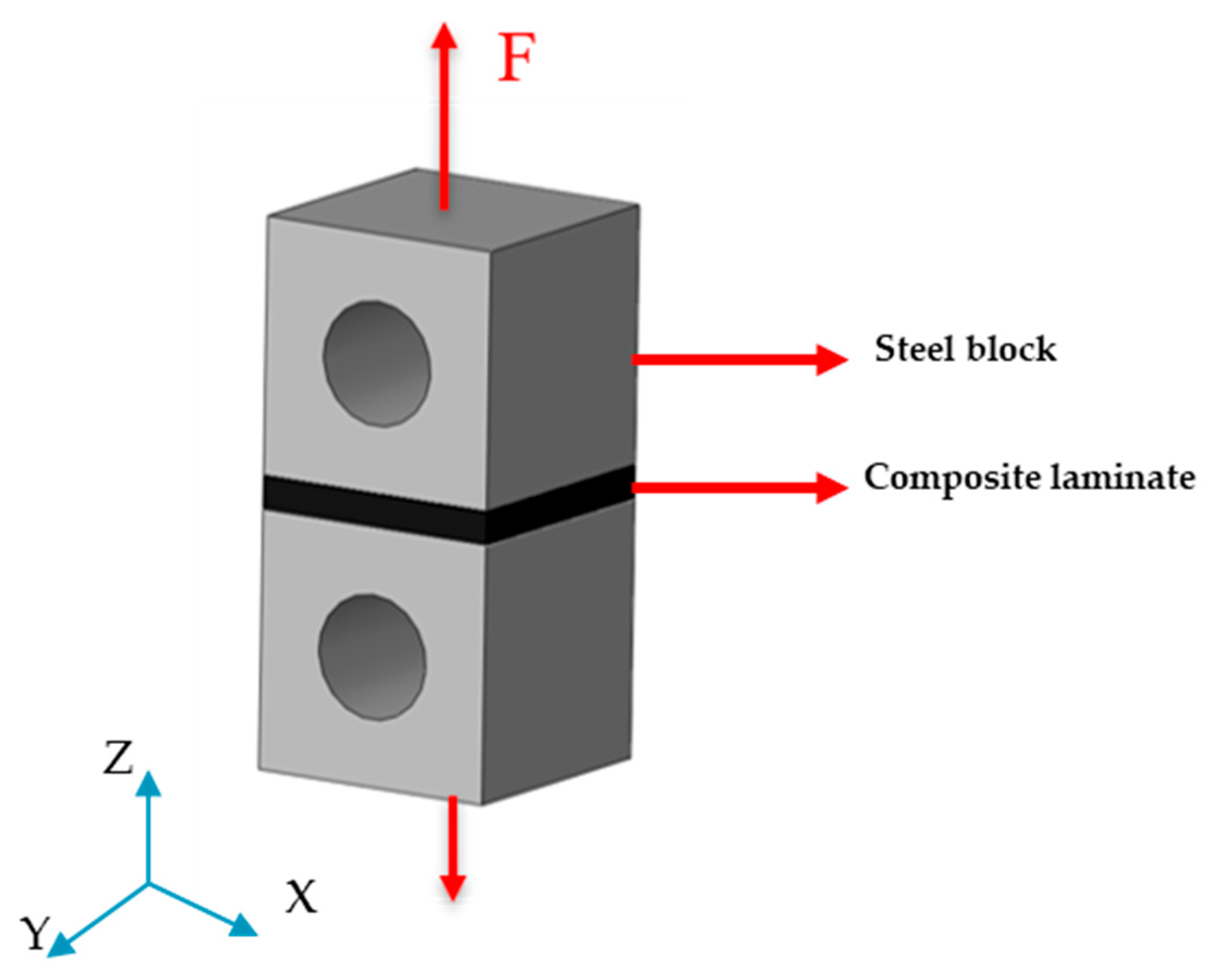
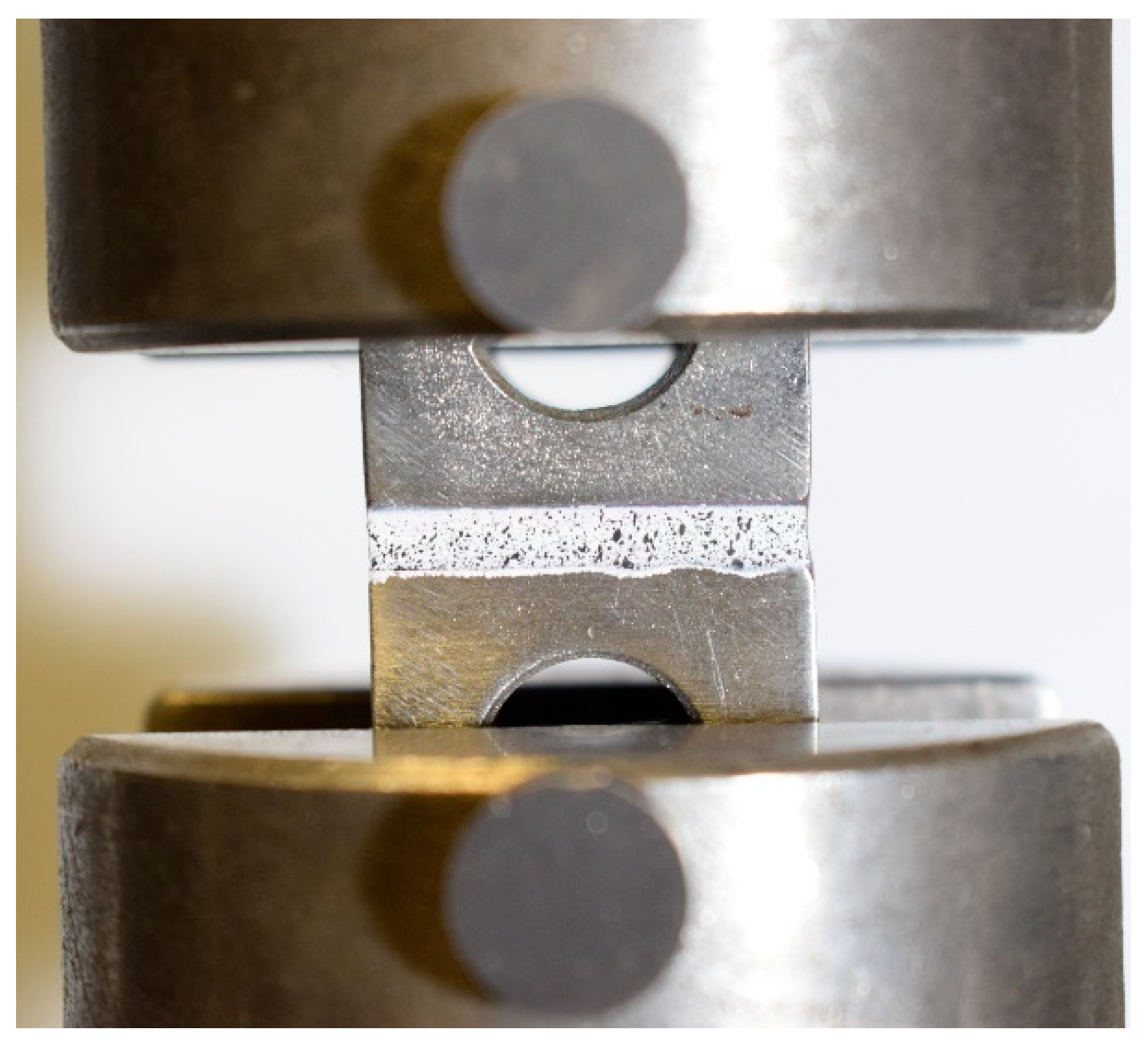
2.6. Testing Condition
3. Numerical Study
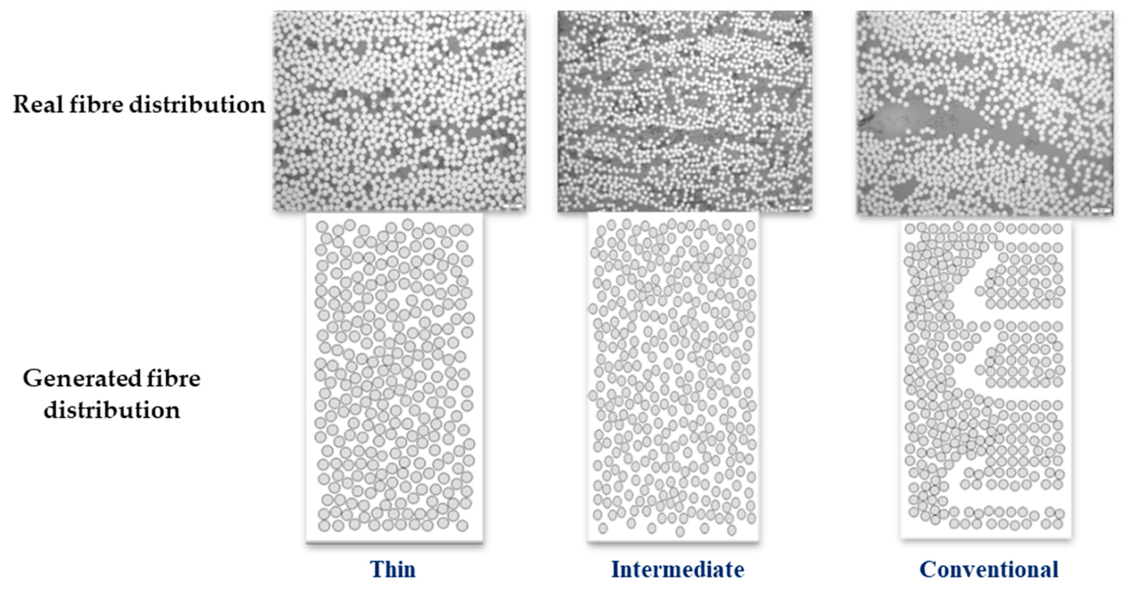
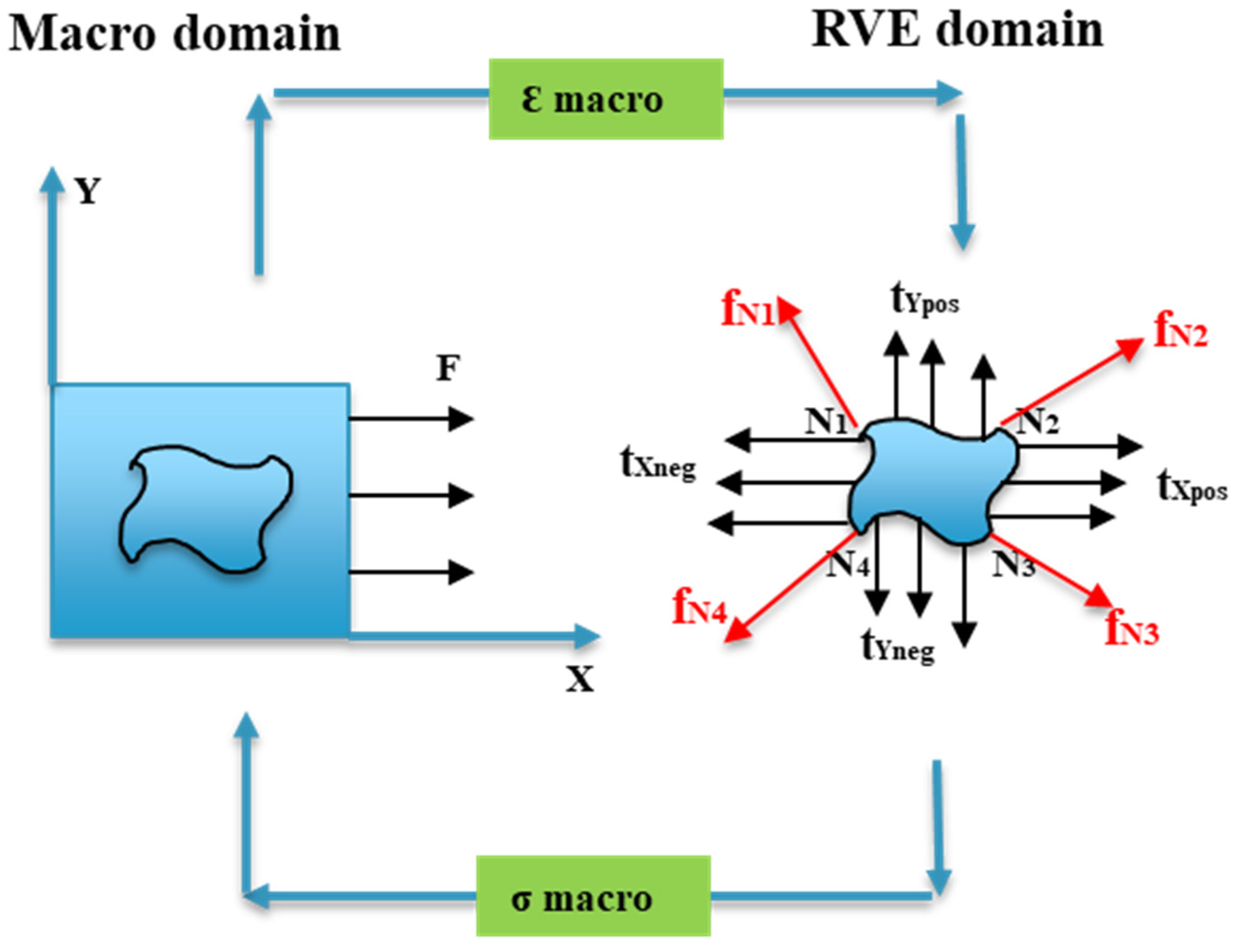
3.1. Generating Representative Volume Element

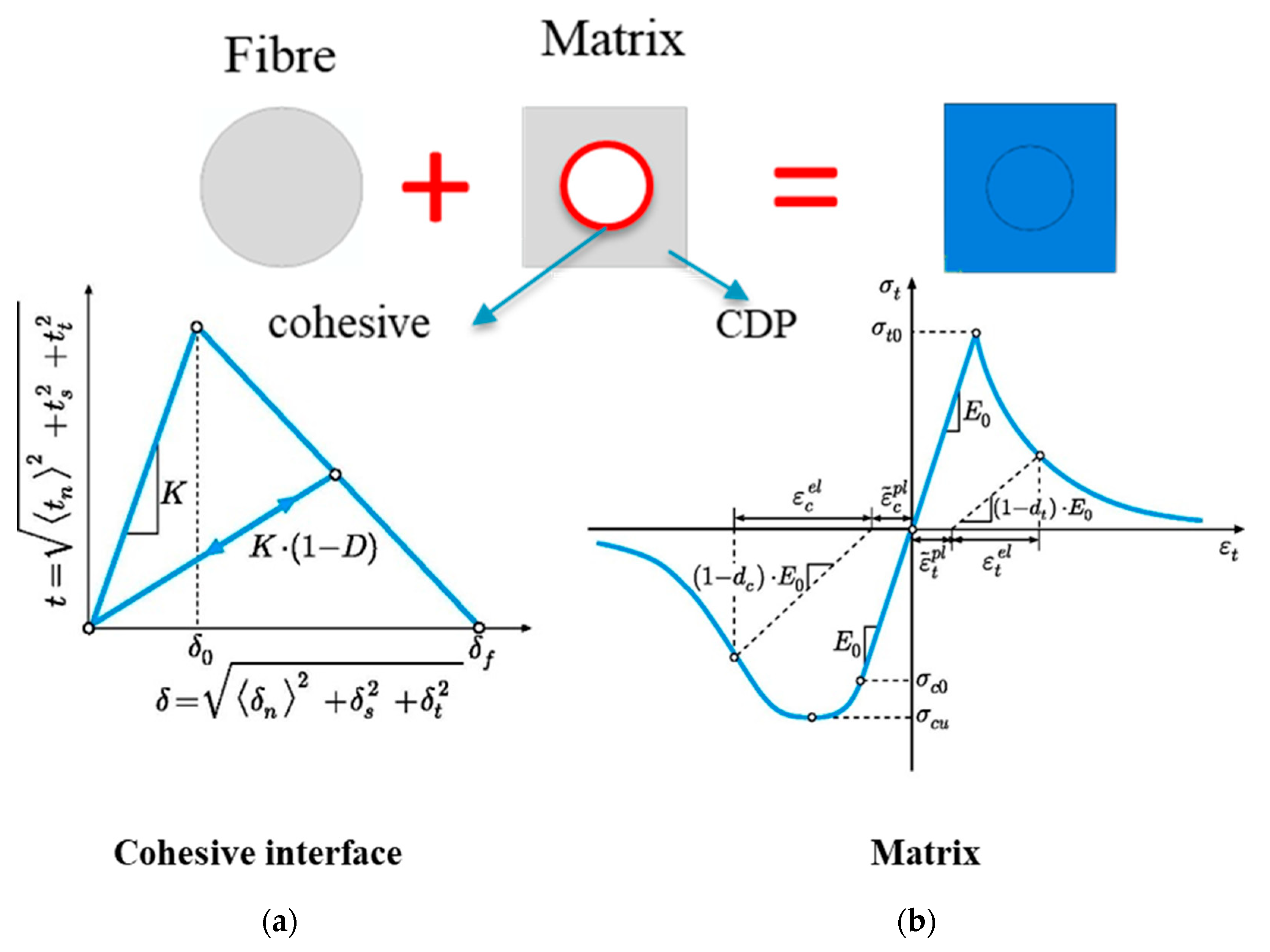
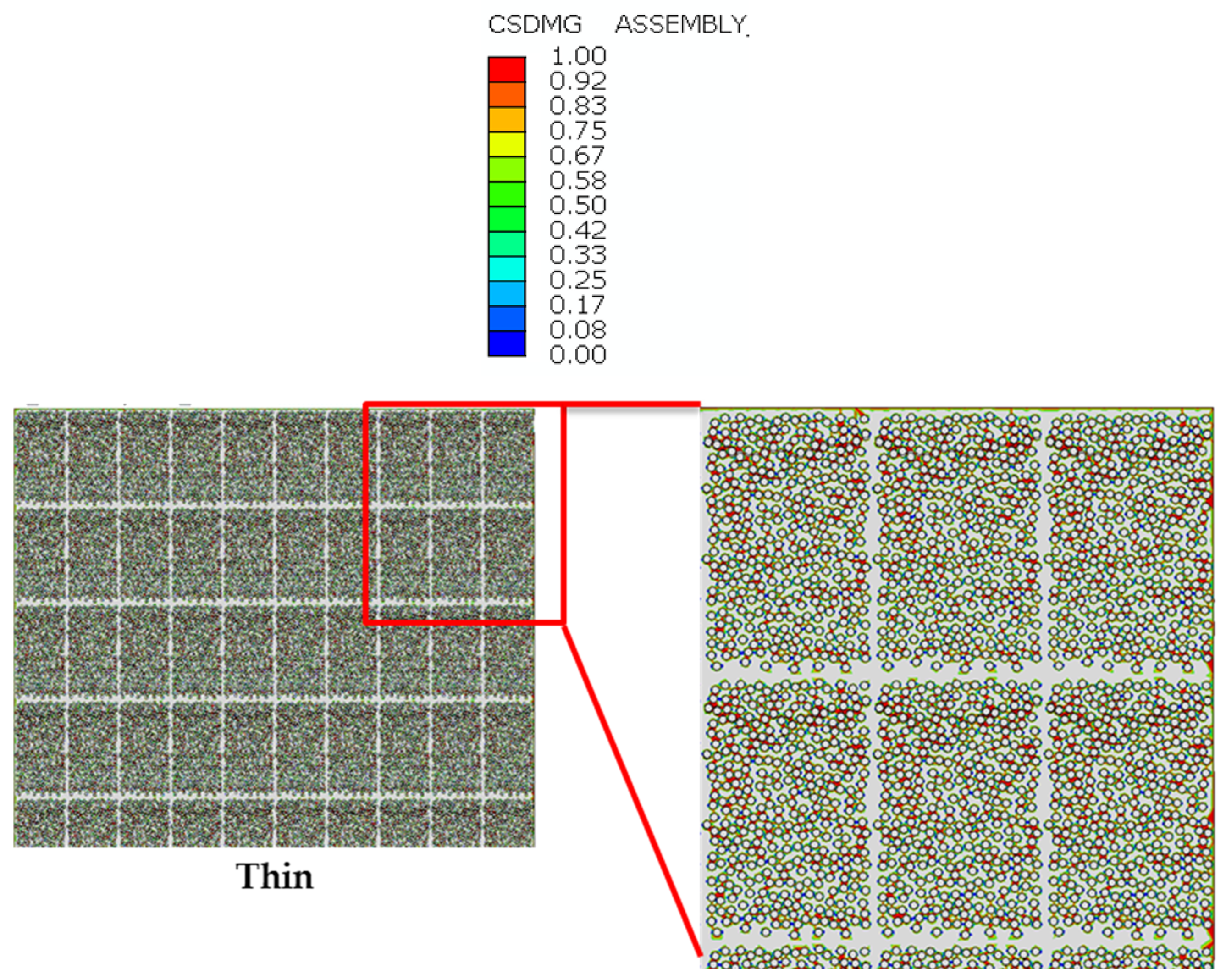
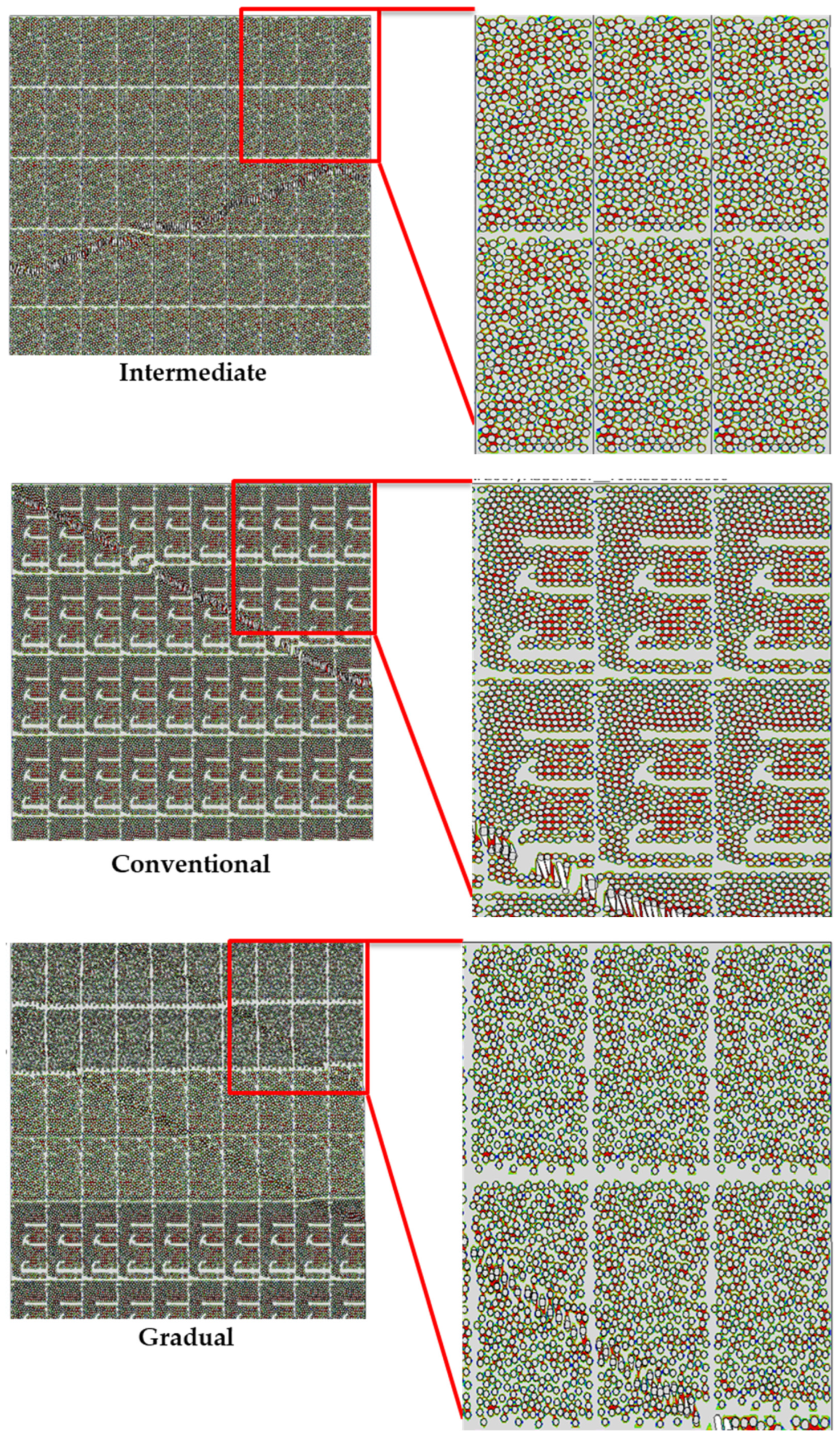
3.2. Matrix Damage Plasticity Criteria Model
3.3. Fiber–Matrix Interface Model
4. Results and Discussion
4.1. Experimental Results and Discussion
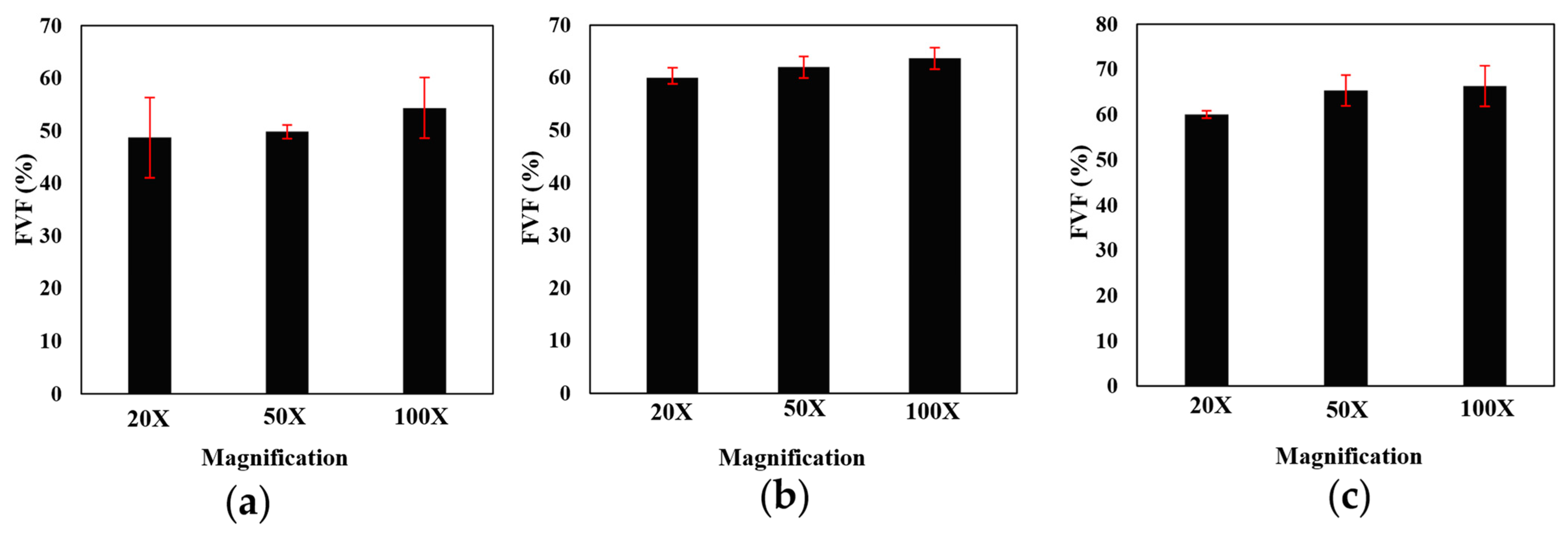
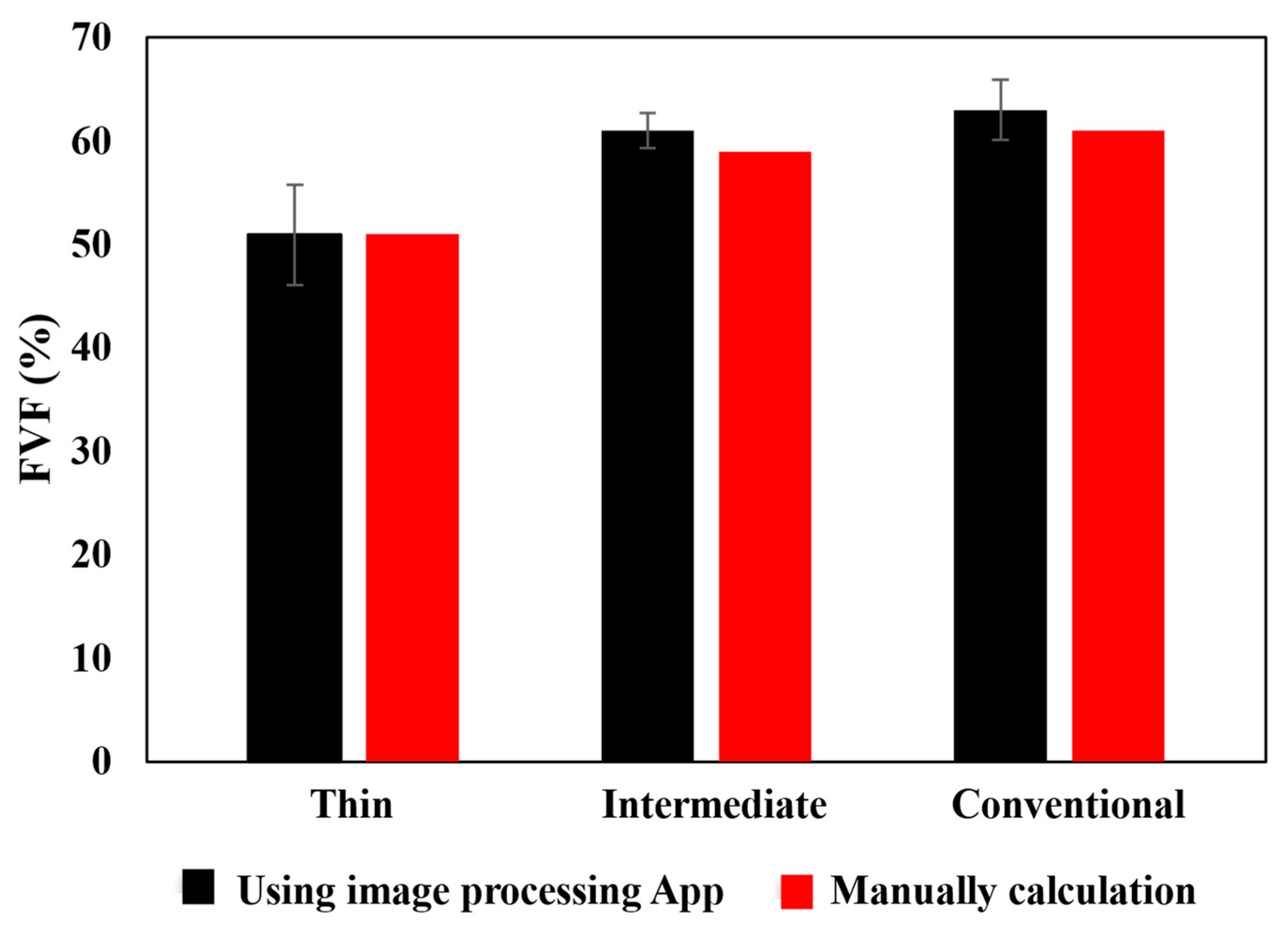
4.1.1. Fiber Volume Fraction (FVF)
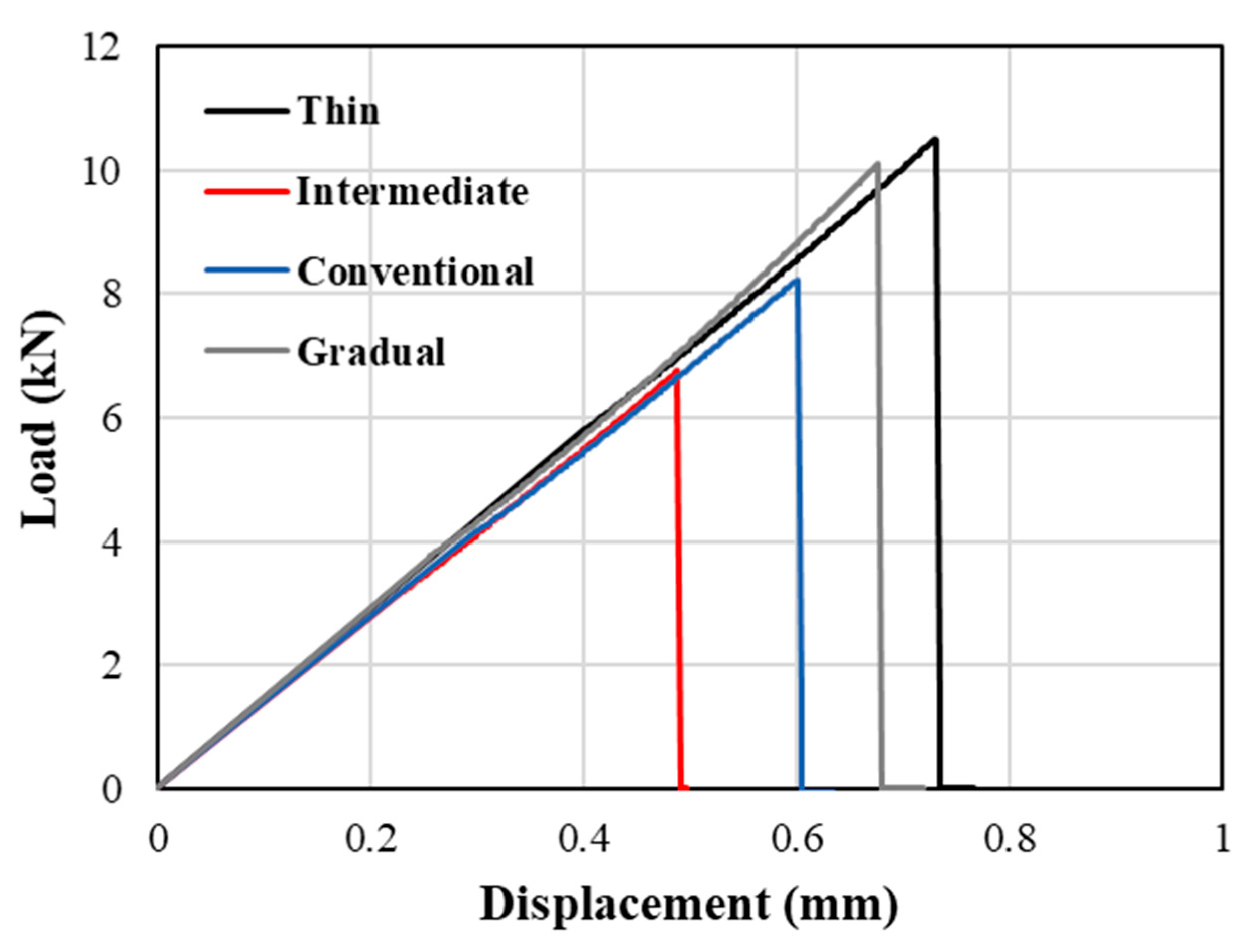
4.1.2. Transverse Tensile Tests
4.2. Numerical Results and Discussion
5. Conclusions
Author Contributions
Funding
Institutional Review Board Statement
Informed Consent Statement
Data Availability Statement
Conflicts of Interest
References
- Malekinejadbahabadi, H.; Farrokhabadi, A.; Rahimi, G.; Nazerigivi, A. Effect of core shape on debonding failure of composite sandwich panels with foam-filled corrugated core. Steel Compos. Struct. 2022, 45, 467–482. [Google Scholar]
- An Introduction to Composite Materials—T. W. Clyne, D. Hull—Google Books. Available online: https://books.google.pt/books?hl=en&lr=&id=4oKWDwAAQBAJ&oi=fnd&pg=PR11&dq=composite+materials&ots=YWTX1AIfDs&sig=qPi1iSBmZxfKpWJFhl2LLSuNat0&redir_esc=y#v=onepage&q=compositematerials&f=false (accessed on 12 May 2024).
- Nickel, J.; Riedel, U. Activities in biocomposites. Mater. Today 2003, 6, 44–48. [Google Scholar] [CrossRef]
- Bahabadi, M.; Farrokhabadi, A.; Khatibi, M.M.; Rahmani, R. Investigation of skin/core debonding effects on the natural frequencies of composite sandwich structures using experimental and numerical modal analysis. J. Sci. Technol. Compos. 2018, 5, 91–98. [Google Scholar] [CrossRef]
- Vasiliev, V.V.; Morozov, E.V. Advanced Mechanics of Composite Materials. Adv. Mech. Compos. Mater. 2007. [Google Scholar] [CrossRef]
- Ramezani, F.; Carbas, R.J.C.; Marques, E.A.S.; Ferreira, A.M.; da Silva, L.F.M. A study of the fracture mechanisms of hybrid carbon fiber reinforced polymer laminates reinforced by thin-ply. Polym. Compos. 2023, 44, 1672–1683. [Google Scholar] [CrossRef]
- Adams, R.D.; da Silva, L.F.M.; Öchsner, A. Handbook of Adhesion Technology: Second Editio; Springer Nature: Berlin, Germany, 2018. [Google Scholar] [CrossRef]
- Abrate, S. Impact on Laminated Composite Materials. Appl. Mech. Rev. 1991, 44, 155–190. [Google Scholar] [CrossRef]
- Su, K. Delamination Resistance of Stitched Thermoplastic Matrix Composite Laminates; ASTM: West Conshohocken, PA, USA, 1989. [Google Scholar]
- McCartney, L.N. Physically based damage models for laminated composites. Proc. Inst. Mech. Eng. Part L J. Mater. Des. Appl. 2003, 217, 163–199. [Google Scholar] [CrossRef]
- Arteiro, A.; Catalanotti, G.; Xavier, J.; Linde, P.; Camanho, P.P. A strategy to improve the structural performance of non-crimp fabric thin-ply laminates. Compos. Struct. 2018, 188, 438–449. [Google Scholar] [CrossRef]
- Kötter, B.; Karsten, J.; Körbelin, J.; Fiedler, B. CFRP Thin-Ply Fibre Metal Laminates: Influences of Ply Thickness and Metal Layers on Open Hole Tension and Compression Properties. Materials 2020, 13, 910. [Google Scholar] [CrossRef]
- Sihn, S.; Kim, R.Y.; Kawabe, K.; Tsai, S.W. Experimental studies of thin-ply laminated composites. Compos. Sci. Technol. 2007, 67, 996–1008. [Google Scholar] [CrossRef]
- Amacher, R.; Cugnoni, J.; Botsis, J.; Sorensen, L.; Smith, W.; Dransfeld, C. Thin ply composites: Experimental characterization and modeling of size-effects. Compos. Sci. Technol. 2014, 101, 121–132. [Google Scholar] [CrossRef]
- Zhang, J.-N.; Wang, C.-Y.; Guo, Z.; Zhou, Y.-G.; Wu, H.-H. Prediction on electrical resistivity of thin-ply unidirectional composites considering electric tunnel effect. Polym. Compos. 2020, 41, 4318–4328. [Google Scholar] [CrossRef]
- Petkov, V.I.; Joffe, R.; Fernberg, P. Thermal oxidative aging of satin weave and thin-ply polyimide composites. Polym. Compos. 2022, 43, 2615–2627. [Google Scholar] [CrossRef]
- Xia, Z.; Zhang, Y.; Ellyin, F. A unified periodical boundary conditions for representative volume elements of composites and applications. Int. J. Solids Struct. 2003, 40, 1907–1921. [Google Scholar] [CrossRef]
- Yuan, Z.; Fish, J. Toward realization of computational homogenization in practice. Int. J. Numer. Methods Eng. 2008, 73, 361–380. [Google Scholar] [CrossRef]
- Lubliner, J.; Oliver, J.; Oller, S.; Oñate, E. A plastic-damage model for concrete. Int. J. Solids Struct. 1989, 25, 299–326. [Google Scholar] [CrossRef]
- Jeeho, L.; Fenves, G.L. Plastic-Damage Model for Cyclic Loading of Concrete Structures. J. Eng. Mech. 1998, 124, 892–900. [Google Scholar] [CrossRef]
- Cugnoni, J.; Amacher, R.; Kohler, S.; Brunner, J.; Kramer, E.; Dransfeld, C.; Smith, W.; Scobbie, K.; Sorensen, L.; Botsis, J. Towards aerospace grade thin-ply composites: Effect of ply thickness, fibre, matrix and interlayer toughening on strength and damage tolerance. Compos. Sci. Technol. 2018, 168, 467–477. [Google Scholar] [CrossRef]
- Malekinejad, H.; Carbas, R.J.C.; Akhavan-Safar, A.; Marques, E.A.S.; Sousa, F.C.; da Silva, L.F.M. Enhancing Fatigue Life and Strength of Adhesively Bonded Composite Joints: A Comprehensive Review. Materials 2023, 16, 6468. [Google Scholar] [CrossRef]
- Costa, R.D.F.S.; Sales-Contini, R.C.M.; Silva, F.J.G.; Sebbe, N.; Jesus, A.M.P. A Critical Review on Fiber Metal Laminates (FML): From Manufacturing to Sustainable Processing. Metals 2023, 13, 638. [Google Scholar] [CrossRef]
- Eslami-Farsani, R.; Aghamohammadi, H.; Khalili, S.M.R.; Ebrahimnezhad-Khaljiri, H.; Jalali, H. Recent trend in developing advanced fiber metal laminates reinforced with nanoparticles: A review study. J. Ind. Text. 2020, 51 (Suppl. S5), 7374S–7408S. [Google Scholar] [CrossRef]
- Canal, L.P.; González, C.; Segurado, J.; LLorca, J. Intraply fracture of fiber-reinforced composites: Microscopic mechanisms and modeling. Compos. Sci. Technol. 2012, 72, 1223–1232. [Google Scholar] [CrossRef]
- Okereke, M.I.; Akpoyomare, A.I. A virtual framework for prediction of full-field elastic response of unidirectional composites. Comput. Mater. Sci. 2013, 70, 82–99. [Google Scholar] [CrossRef]
- Ramezani, F.; Carbas, R.; Marques, E.A.S.; Ferreira, A.M.; da Silva, L.F.M. Study on out-of-plane tensile strength of angle-plied reinforced hybrid CFRP laminates using thin-ply. Mech. Adv. Mater. Struct. 2023, 2859–2872. [Google Scholar] [CrossRef]
- Naya, F.; González, C.; Lopes, C.S.; Van der Veen, S.; Pons, F. Computational micromechanics of the transverse and shear behavior of unidirectional fiber reinforced polymers including environmental effects. Compos. Part A Appl. Sci. Manuf. 2017, 92, 146–157. [Google Scholar] [CrossRef]
- Naya, F. Prediction of Mechanical Properties of Unidirectional FRP Plies at Different Environmental Conditions by Means of Computational Micromechanics. Ph.D. Thesis, University of Madrid, Madrid, Spain, 2017. [Google Scholar] [CrossRef]
- ABAQUS. Abaqus 6.14 Documentation. Abaqus 6.14 Analysis User’s Guide. Available online: http://62.108.178.35:2080/v6.14/index.html (accessed on 24 September 2021).
- Herráez, M.; González, C.; Lopes, C.S.; De Villoria, R.G.; LLorca, J.; Varela, T.; Sánchez, J. Computational micromechanics evaluation of the effect of fibre shape on the transverse strength of unidirectional composites: An approach to virtual materials design. Compos. Part A Appl. Sci. Manuf. 2016, 91, 484–492. [Google Scholar] [CrossRef]
- Rafie, A.; Madadi, H.; Farrokhabadi, A.; Herráez, M. In situ strength analysis of cross-ply composite laminates containing defects and interleaved woven layer using a computational micromechanics approach. Fatigue Fract. Eng. Mater. Struct. 2021, 44, 1225–1240. [Google Scholar] [CrossRef]
- Bahabadi, H.M.; Farrokhabadi, A.; Rahimi, G.H. Investigation of debonding growth between composite skins and corrugated foam-composite core in sandwich panels under bending loading. Eng. Fract. Mech. 2020, 230, 106987. [Google Scholar] [CrossRef]
- Benzeggagh, M.L.; Kenane, M. Measurement of mixed-mode delamination fracture toughness of unidirectional glass/epoxy composites with mixed-mode bending apparatus. Compos. Sci. Technol. 1996, 56, 439–449. [Google Scholar] [CrossRef]
- MIP.4 FULL Software. Available online: https://metsofts.ir/products/MIP/MIP%20Catalog-Medium.pdf (accessed on 12 May 2024).
- Galos, J. Thin-ply composite laminates: A review. Compos. Struct. 2020, 236, 111920. [Google Scholar] [CrossRef]
- Hori, M.; Nemat-Nasser, S. On two micromechanics theories for determining micro–macro relations in heterogeneous solids. Mech. Mater. 1999, 31, 667–682. [Google Scholar] [CrossRef]
- Nemat-Nasser, S. Averaging theorems in finite deformation plasticity. Mech. Mater. 1999, 31, 493–523. [Google Scholar] [CrossRef]


Disclaimer/Publisher’s Note: The statements, opinions and data contained in all publications are solely those of the individual author(s) and contributor(s) and not of MDPI and/or the editor(s). MDPI and/or the editor(s) disclaim responsibility for any injury to people or property resulting from any ideas, methods, instructions or products referred to in the content. |
© 2024 by the authors. Licensee MDPI, Basel, Switzerland. This article is an open access article distributed under the terms and conditions of the Creative Commons Attribution (CC BY) license (https://creativecommons.org/licenses/by/4.0/).
Share and Cite
Malekinejad, H.; Ramezani, F.; Carbas, R.J.C.; Marques, E.A.S.; da Silva, L.F.M. Study of CFRP Laminate Gradually Modified throughout the Thickness Using Thin Ply under Transvers Tensile Loading. Materials 2024, 17, 2388. https://doi.org/10.3390/ma17102388
Malekinejad H, Ramezani F, Carbas RJC, Marques EAS, da Silva LFM. Study of CFRP Laminate Gradually Modified throughout the Thickness Using Thin Ply under Transvers Tensile Loading. Materials. 2024; 17(10):2388. https://doi.org/10.3390/ma17102388
Chicago/Turabian StyleMalekinejad, Hossein, Farin Ramezani, Ricardo J. C. Carbas, Eduardo A. S. Marques, and Lucas F. M. da Silva. 2024. "Study of CFRP Laminate Gradually Modified throughout the Thickness Using Thin Ply under Transvers Tensile Loading" Materials 17, no. 10: 2388. https://doi.org/10.3390/ma17102388