

Synthesis and Catalytic Performance of Mo2C/MoS2 Composite Heterojunction Catalysts

Abstract
1. Introduction
2. Materials and Method
2.1. Materials
2.2. Synthesis of Electrocatalysts
2.3. Characterization
2.4. Electrochemical Test
3. Results and Discussion
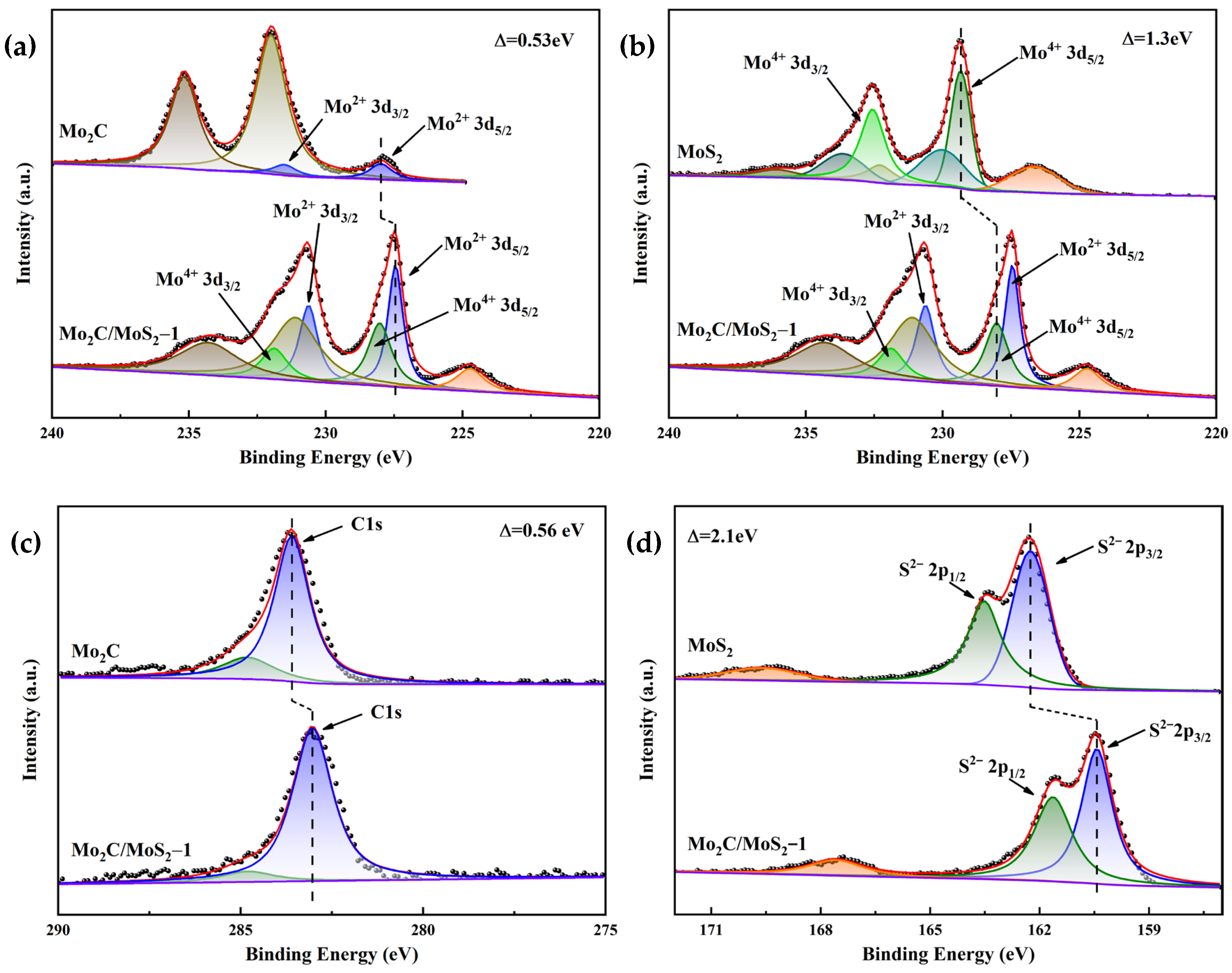
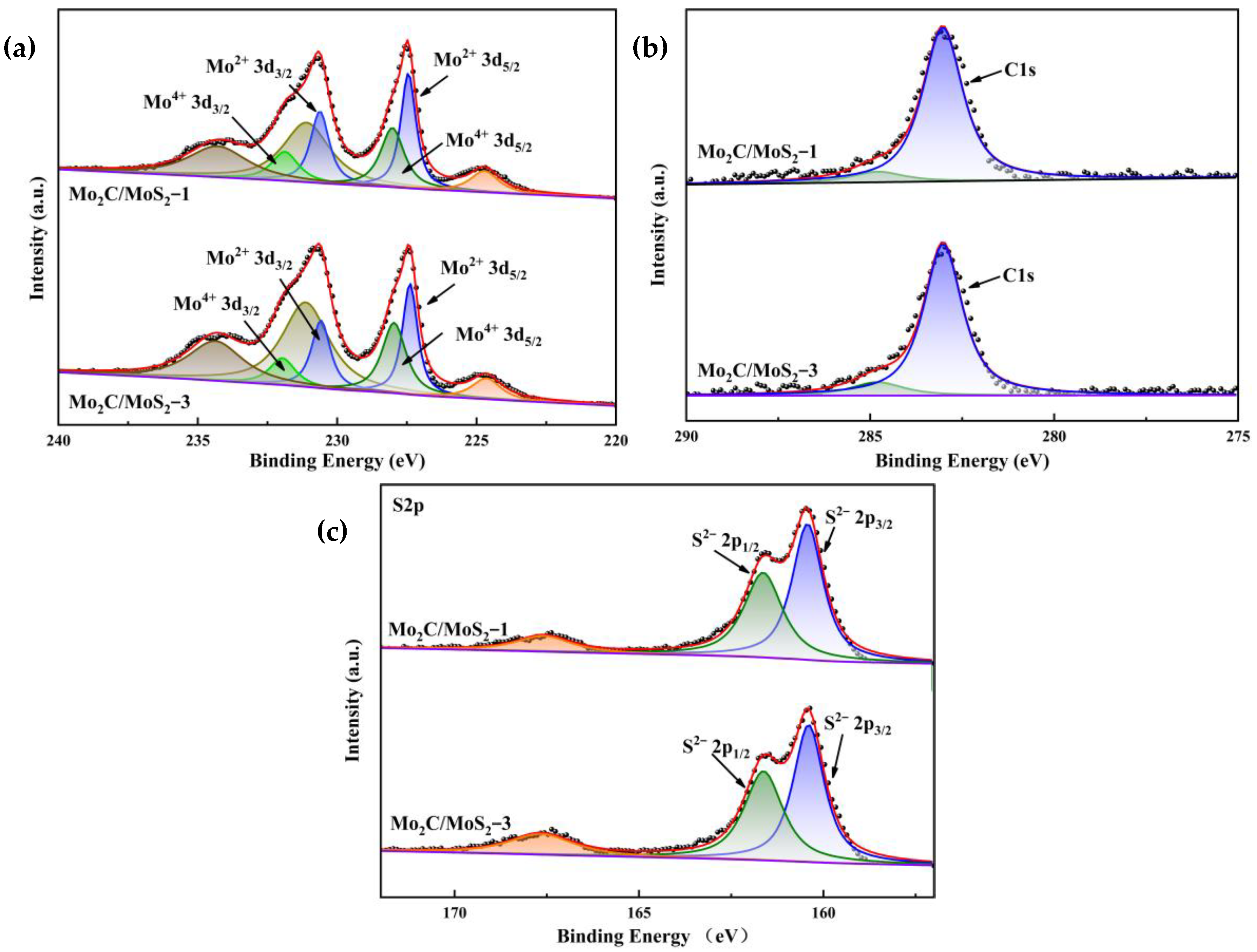
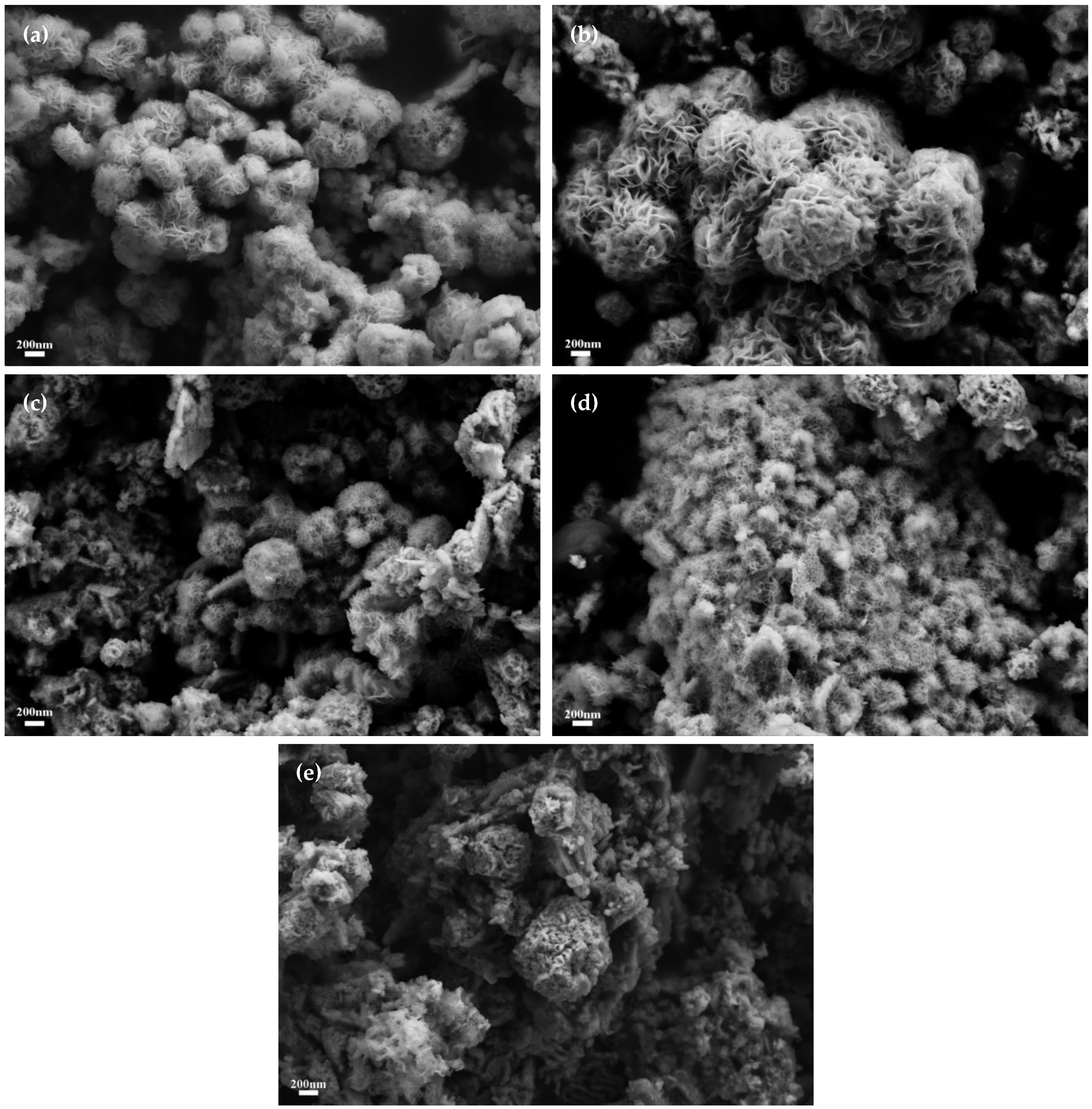
3.1. Characterization of Electrocatalysts
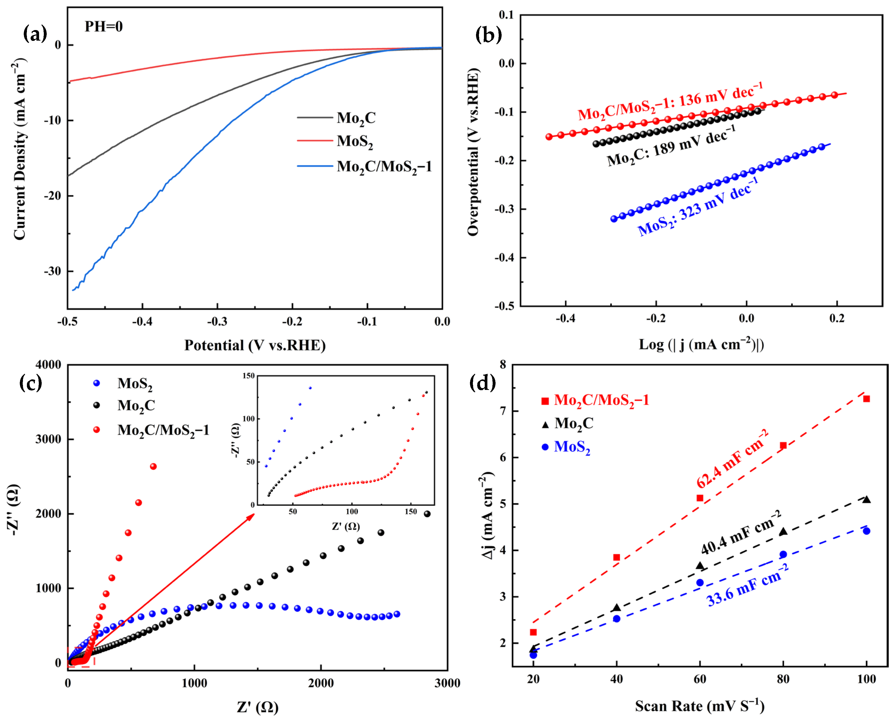
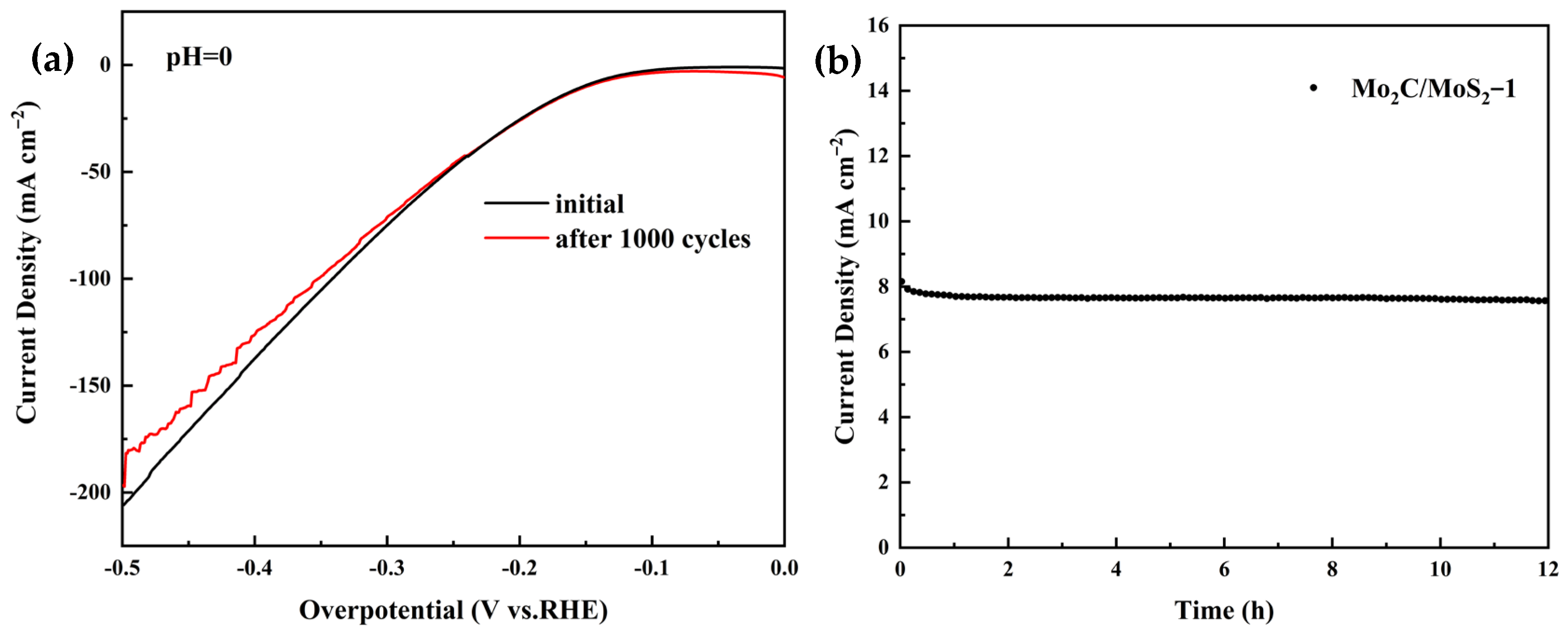
3.2. Electrochemical Results of Electrocatalysts
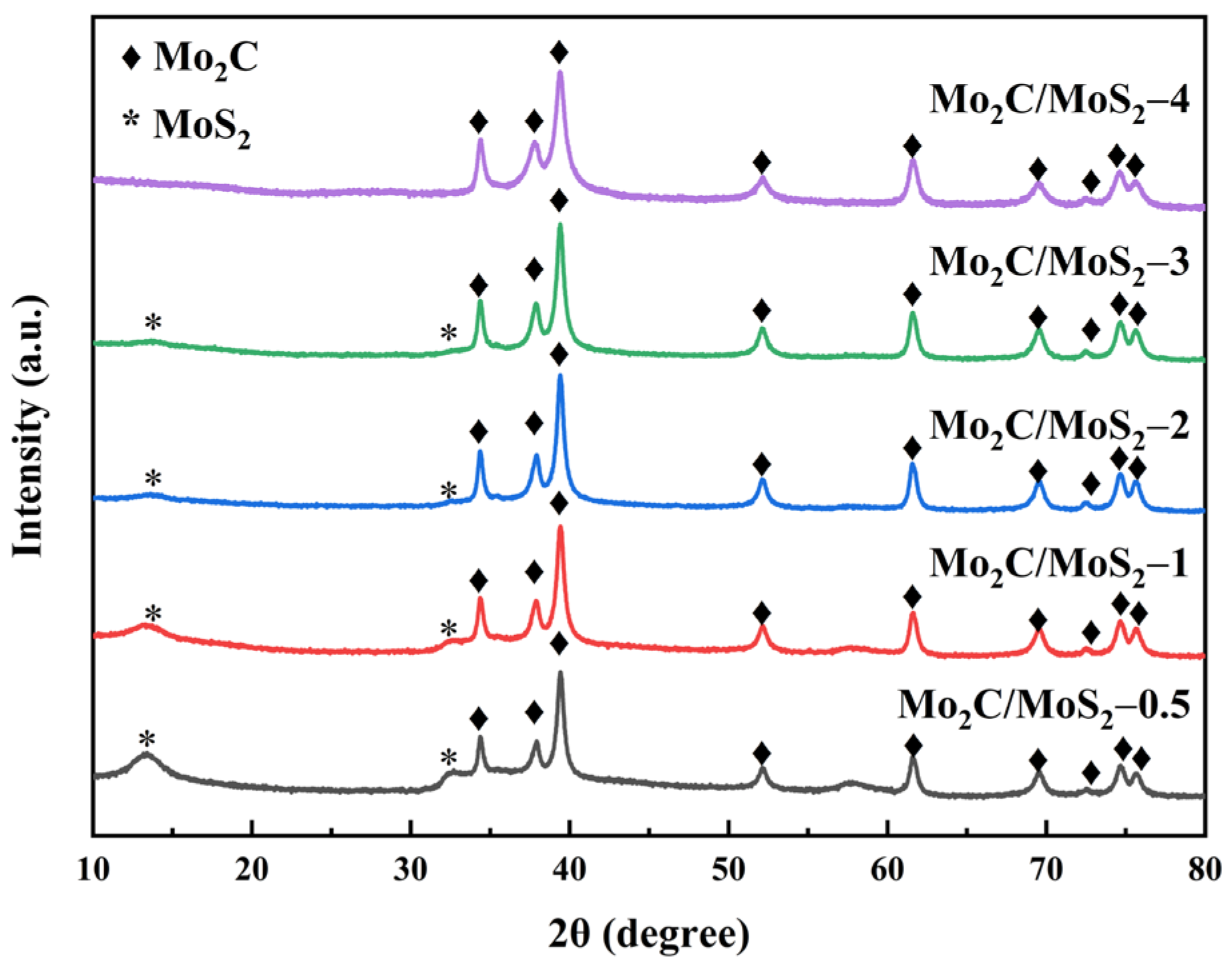
3.3. Characterization of Composite Catalysts with Different Molar Ratios
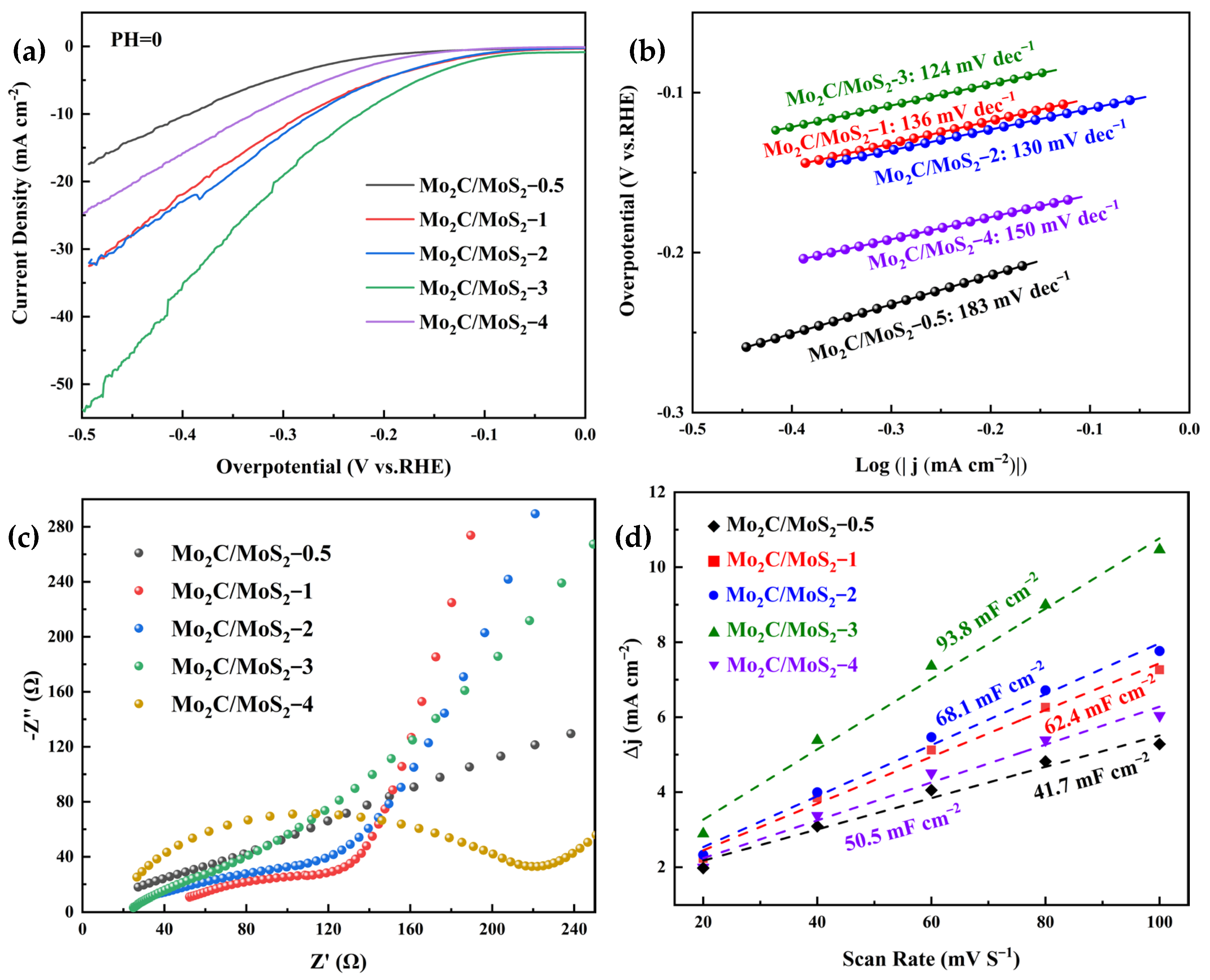
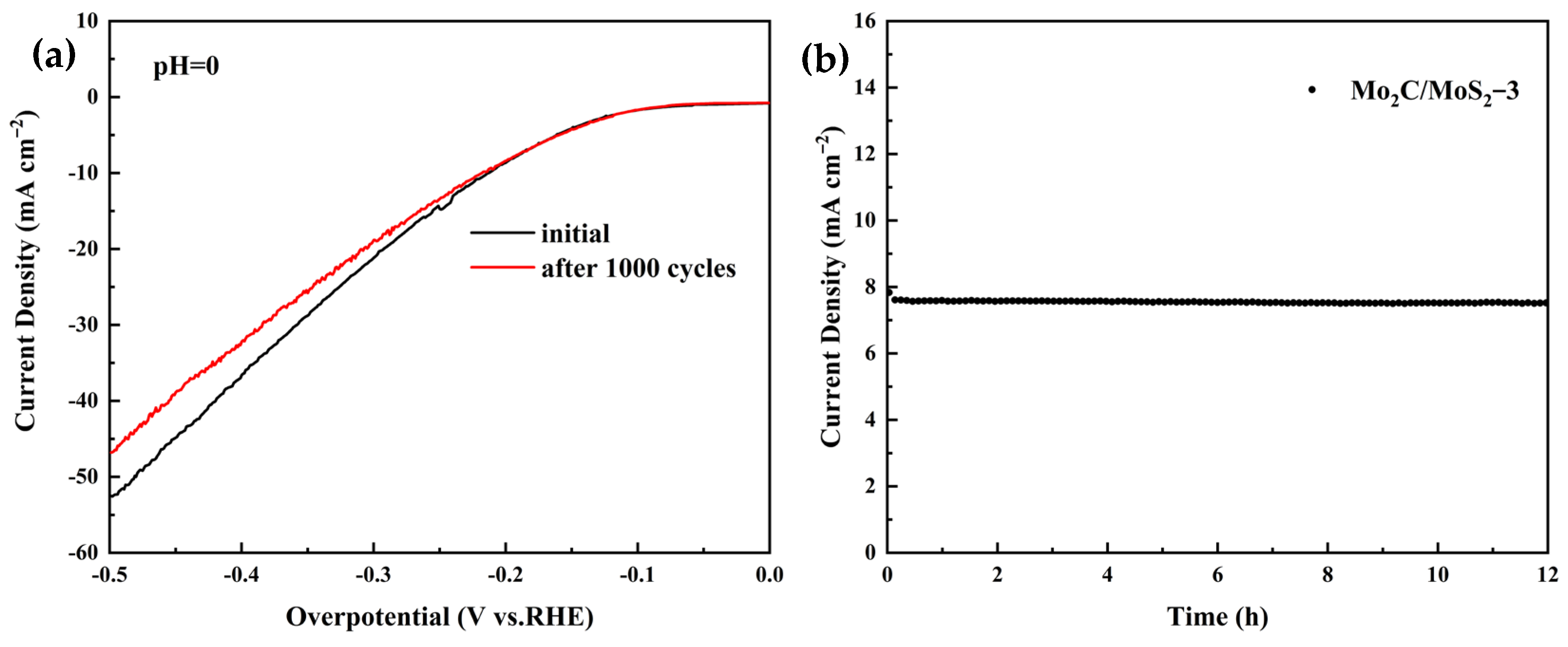
3.4. Electrochemical Results of Composite Catalysts with Different Molar Ratios
4. Conclusions
Author Contributions
Funding
Institutional Review Board Statement
Informed Consent Statement
Data Availability Statement
Acknowledgments
Conflicts of Interest
References
- Turner, J.A. Sustainable hydrogen production. Science 2004, 305, 972–974. [Google Scholar] [CrossRef] [PubMed]
- Shoaib, M.; Naz, M.Y.; Shukrullah, S.; Munir, M.A.; Irfan, M.; Rahman, S.; Ghanim, A.A.J. Dual S-Scheme Heterojunction CdS/TiO2/g-C3N4 Photocatalyst for Hydrogen Production and Dye Degradation Applications. ACS Omega 2023, 8, 43139–43150. [Google Scholar] [CrossRef] [PubMed]
- Sun, F.; Song, J.; Wen, H.; Cao, X.; Zhao, F.; Qin, J.; Mao, W.; Tang, X.; Dong, L.; Long, Y. Ce4+/Ce3+ Redox Effect-Promoted CdS/CeO2 Heterojunction Photocatalyst for the Atom Economic Synthesis of Imines under Visible Light. Inorg. Chem. 2023, 62, 17961–17971. [Google Scholar] [CrossRef]
- Lu, Z.; Yang, H.; Liu, Q.; Luo, J.; Feng, L.; Chu, L.; Liu, X. Nb2AlC MAX Nanosheets Supported Ru Nanocrystals as Efficient Catalysts for Boosting pH-Universal Hydrogen Production. Small 2023, 20, e2305434. [Google Scholar] [CrossRef]
- Morales-Guio, C.G.; Stern, L.A.; Hu, X.L. Nanostructured hydrotreating catalysts for electrochemical hydrogen evolution. Chem. Soc. Rev. 2014, 43, 6555–6569. [Google Scholar] [CrossRef]
- Popczun, E.J.; McKone, J.R.; Read, C.G.; Biacchi, A.J.; Wiltrout, A.M.; Lewis, N.S.; Schaak, R.E. Nanostructured Nickel Phosphide as an Electrocatalyst for the Hydrogen Evolution Reaction. J. Am. Chem. Soc. 2013, 135, 9267–9270. [Google Scholar] [CrossRef] [PubMed]
- Alptekin, F.M.; Celiktas, M.S. Review on Catalytic Biomass Gasification for Hydrogen Production as a Sustainable Energy Form and Social, Technological, Economic, Environmental, and Political Analysis of Catalysts. ACS Omega 2022, 7, 24918–24941. [Google Scholar] [CrossRef] [PubMed]
- Anniwaer, A.; Chaihad, N.; Zhang, M.; Wang, C.; Yu, T.; Kasai, Y.; Abudula, A.; Guan, G. Hydrogen-rich gas production from steam co-gasification of banana peel with agricultural residues and woody biomass. Waste Manag. 2021, 125, 204–214. [Google Scholar] [CrossRef]
- Luo, Y.; Chen, J.; Wang, T. Evaluation of the Effect of CaO on Hydrogen Production by Sorption-Enhanced Steam Methane Reforming. ACS Omega 2024, 9, 5330–5337. [Google Scholar] [CrossRef] [PubMed]
- Yusuf, B.O.; Umar, M.; Kotob, E.; Abdulhakam, A.; Taialla, O.A.; Awad, M.M.; Hussain, I.; Alhooshani, K.R.; Ganiyu, S.A. Recent Advances in Bimetallic Catalysts for Methane Steam Reforming in Hydrogen Production: Current Trends, Challenges, and Future Prospects. Chem. Asian J. 2023. online version of record. [Google Scholar] [CrossRef] [PubMed]
- Maček Kržmanc, M.; Daneu, N.; Čontala, A.; Santra, S.; Kamal, K.M.; Likozar, B.; Spreitzer, M. SrTiO3/Bi4Ti3O12 Nanoheterostructural Platelets Synthesized by Topotactic Epitaxy as Effective Noble-Metal-Free Photocatalysts for pH-Neutral Hydrogen Evolution. ACS Appl. Mater. Interfaces 2021, 13, 370–381. [Google Scholar] [CrossRef] [PubMed]
- Yang, Y.; Liu, L.; Wu, J.; Qian, X. Hierarchical Bi2S3@CoS2/MoS2 core-shelled microspheres as bifunctional electrode catalysts for efficient triiodide reduction and alkaline hydrogen evolution reactions. J. Alloys Compd. 2022, 924, 166548. [Google Scholar] [CrossRef]
- Li, L.; Wang, P.; Shao, Q.; Huang, X. Metallic nanostructures with low dimensionality for electrochemical water splitting. Chem. Soc. Rev. 2020, 49, 3072–3106. [Google Scholar] [CrossRef] [PubMed]
- Fernandes, V.R.; Pinto, A.M.F.R.; Rangel, C.M. Hydrogen production from sodium borohydride in methanol–water mixtures. Int. J. Hydrogen Energy 2010, 35, 9862–9868. [Google Scholar] [CrossRef]
- Merki, D.; Hu, X. Recent developments of molybdenum and tungsten sulfides as hydrogen evolution catalysts. Energy Environ. Sci. 2011, 4, 3878–3888. [Google Scholar] [CrossRef]
- Wu, H.; Shi, L.; Feng, C.; Ding, Y. Synthesis of MoS2/CoSe2-x hybrids as electrocatalysts for hydrogen evolution reaction. Ionics 2022, 28, 1337–1345. [Google Scholar] [CrossRef]
- Bernsmeier, D.; Selve, S.; Nissen, J.; Maticiuc, N.; Ibaceta-Jana, J.; Szyszka, B.; Muydinov, R. Gas Flow Sputtering of Pt/C Films and their Performance in Electrocatalytic Hydrogen Evolution Reaction. ChemPhysChem 2023, 24, e202200650. [Google Scholar] [CrossRef]
- Liu, Y.; Xu, S.; Zheng, X.; Lu, Y.; Li, D.; Jiang, D. Ru-doping modulated cobalt phosphide nanoarrays as efficient electrocatalyst for hydrogen evolution rection. J. Colloid Interface Sci. 2022, 625, 457–465. [Google Scholar] [CrossRef] [PubMed]
- Park, S.H.; Jo, T.H.; Lee, M.H.; Kawashima, K.; Mullins, C.B.; Lim, H.-K.; Youn, D.H. Highly active and stable nickel–molybdenum nitride (Ni2Mo3N) electrocatalyst for hydrogen evolution. J. Mater. Chem. A 2021, 9, 4945–4951. [Google Scholar] [CrossRef]
- Liu, Y.; Kelly, T.G.; Chen, J.G.; Mustain, W.E. Metal Carbides as Alternative Electrocatalyst Supports. Acs Catal. 2013, 3, 1184–1194. [Google Scholar] [CrossRef] [PubMed]
- Zhong, Y.; Zhao, X.J.; Feng, Y.L.; Lu, H.; Yin, P.; Chen, Z.R.; Jie, Y.; Guo, J.Y.; Pu, M.; Yan, H. DFT study on the electrochemical synthesis of ammonia over Mo2C(121) with N-doping. Mol. Catal. 2022, 530, 112637. [Google Scholar] [CrossRef]
- Noerskov, J.K.; Bligaard, T.; Logadottir, A.; Kitchin, J.R.; Chen, J.G.; Pandelov, S.; Stimming, U. Trends in the Exchange Current for Hydrogen Evolution. ChemInform 2005, 36, 23–26. [Google Scholar] [CrossRef]
- Li, H.; Li, Y.; Aljarb, A.; Shi, Y.; Li, L.-J. Epitaxial Growth of Two-Dimensional Layered Transition-Metal Dichalcogenides: Growth Mechanism, Controllability, and Scalability. Chem. Rev. 2018, 118, 6134–6150. [Google Scholar] [CrossRef] [PubMed]
- Jellinek, F.; Brauer, G.; MÜLler, H. Molybdenum and Niobium Sulphides. Nature 1960, 185, 376–377. [Google Scholar] [CrossRef]
- Zhou, D.; Shu, H.-b.; Hu, C.; Jiang, L.; Liang, P.; Chen, X. Unveiling the Growth Mechanism of MoS2 with Chemical Vapor Deposition: From Two-Dimensional Planar Nucleation to Self-Seeding Nucleation. Cryst. Growth Des. 2018, 18, 1012–1019. [Google Scholar] [CrossRef]
- Ma, W.; Dong, Y.; Li, J.; Wang, Y.; Wang, T.; Zheng, X.; Deng, Y. Recent strategies for improving the catalytic activity of ultrathin transition metal sulfide nanosheets toward the oxygen evolution reaction. Mater. Today Energy 2024, 40, 101492. [Google Scholar] [CrossRef]
- Zahra, R.; Pervaiz, E.; Yang, M.H.; Rabi, O.; Saleem, Z.; Ali, M.; Farrukh, S. A review on nickel cobalt sulphide and their hybrids: Earth abundant, pH stable electro-catalyst for hydrogen evolution reaction. Int. J. Hydrogen Energy 2020, 45, 24518–24543. [Google Scholar] [CrossRef]
- Bagus, P.S.; Ilton, E.S.; Nelin, C.J. The interpretation of XPS spectra: Insights into materials properties. Surf. Sci. Rep. 2013, 68, 273–304. [Google Scholar] [CrossRef]
- Li, C.; Zhang, N.; Gao, P. Lessons learned: How to report XPS data incorrectly about lead-halide perovskites. Mater. Chem. Front. 2023, 7, 3797–3802. [Google Scholar] [CrossRef]
- Deng, R.X.; Zhang, H.R.; Zhang, Y.H.; Chen, Z.Y.; Sui, Y.P.; Ge, X.M.; Liang, Y.J.; Hu, S.K.; Yu, G.H.; Jiang, D. Graphene/Mo2C heterostructure directly grown by chemical vapor deposition. Chin. Phys. B 2017, 26, 67901. [Google Scholar] [CrossRef]
- Du, H.; Liu, Y.-N.; Shen, C.-C.; Xu, A.-W. Nanoheterostructured photocatalysts for improving photocatalytic hydrogen production. Chin. J. Catal. 2017, 38, 1295–1306. [Google Scholar] [CrossRef]
- Wang, Q.; Yu, R.; Shen, D.; Liu, G.; Hong Luo, K.; Wu, C.; Gu, S. One-pot synthesis of Mo2C&MoS2 loaded on N/S co-doped carbon materials as the electrocatalyts for hydrogen evolution reaction. Fuel 2022, 318, 123615. [Google Scholar] [CrossRef]
- Zhao, Z.; Qin, F.; Kasiraju, S.; Xie, L.; Alam, M.K.; Chen, S.; Wang, D.; Ren, Z.; Wang, Z.; Grabow, L.C.; et al. Vertically Aligned MoS2/Mo2C hybrid Nanosheets Grown on Carbon Paper for Efficient Electrocatalytic Hydrogen Evolution. Acs Catal. 2017, 7, 7312–7318. [Google Scholar] [CrossRef]
- Gong, L.; Mu, X.; Li, Q.; Ma, L.; Xiong, Y.C.; Li, R. Rational design of Ni-induced NC @Mo2C@MoS2 sphere electrocatalyst for efficient hydrogen evolution reaction in acidic and alkaline media. Int. J. Hydrogen Energy 2021, 46, 5250–5258. [Google Scholar] [CrossRef]
- Yang, S.; Wang, Y.; Zhang, H.; Zhang, Y.; Liu, L.; Fang, L.; Yang, X.; Gu, X.; Wang, Y. Unique three-dimensional Mo2C@MoS2 heterojunction nanostructure with S vacancies as outstanding all-pH range electrocatalyst for hydrogen evolution. J. Catal. 2019, 371, 20–26. [Google Scholar] [CrossRef]


| Equivalent Circuit | Catalysts | RS (Ω) | RCT (Ω) |
|---|---|---|---|
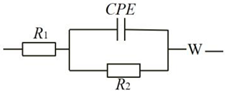 | MoS2 | 36.19 | 890.01 |
| Mo2C | 12.21 | 130.90 | |
| Mo2C/MoS2-1 | 44.37 | 51.86 |
| Equivalent Circuit | Catalysts | RS (Ω) | RCT (Ω) |
|---|---|---|---|
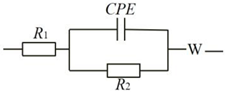 | Mo2C/MoS2-0.5 | 35.23 | 70.28 |
| Mo2C/MoS2-1 | 44.37 | 51.86 | |
| Mo2C/MoS2-2 | 39.45 | 47.86 | |
| Mo2C/MoS2-3 | 21.67 | 39.20 | |
| Mo2C/MoS2-4 | 20.25 | 100.37 |
| Catalysts | Over Potential at 10 mA/cm2 (mV) | Tafel Slope (mV/dec) | ECSA (mF/cm2) | RCT (Ω) | References |
|---|---|---|---|---|---|
| Mo2C/MoS2-3 | 223.4 | 124 | 93.8 | 39.2 | This work |
| Mo2C&MoS2@NSC3 | 220 | 85.5 | 5.6 | / | [32] |
| Mo2C/MoS2-25 min | 63 | 53 | 146 | 7.5 | [33] |
| NC@Mo2C@MoS2-(Ni) | 205 | 61.4 | 4.7 | 45 | [34] |
| 3D MoS2@Mo2C NS | 67 | 37 | 64.2 | / | [35] |
Disclaimer/Publisher’s Note: The statements, opinions and data contained in all publications are solely those of the individual author(s) and contributor(s) and not of MDPI and/or the editor(s). MDPI and/or the editor(s) disclaim responsibility for any injury to people or property resulting from any ideas, methods, instructions or products referred to in the content. |
© 2024 by the authors. Licensee MDPI, Basel, Switzerland. This article is an open access article distributed under the terms and conditions of the Creative Commons Attribution (CC BY) license (https://creativecommons.org/licenses/by/4.0/).
Share and Cite
Zhang, C.; Pan, Z.; Tao, Y. Synthesis and Catalytic Performance of Mo2C/MoS2 Composite Heterojunction Catalysts. Materials 2024, 17, 2355. https://doi.org/10.3390/ma17102355
Zhang C, Pan Z, Tao Y. Synthesis and Catalytic Performance of Mo2C/MoS2 Composite Heterojunction Catalysts. Materials. 2024; 17(10):2355. https://doi.org/10.3390/ma17102355
Chicago/Turabian StyleZhang, Congyi, Zhigang Pan, and Yaqiu Tao. 2024. "Synthesis and Catalytic Performance of Mo2C/MoS2 Composite Heterojunction Catalysts" Materials 17, no. 10: 2355. https://doi.org/10.3390/ma17102355
APA StyleZhang, C., Pan, Z., & Tao, Y. (2024). Synthesis and Catalytic Performance of Mo2C/MoS2 Composite Heterojunction Catalysts. Materials, 17(10), 2355. https://doi.org/10.3390/ma17102355