
An Adaptive Virtual Inertial Control Strategy for DC Distribution Networks


College of Electrical Engineering, Guangxi University, Nanning 530004, China
*
Authors to whom correspondence should be addressed.
Energies 2024, 17(10), 2401; https://doi.org/10.3390/en17102401
Submission received: 16 April 2024
/
Revised: 5 May 2024
/
Accepted: 11 May 2024
/
Published: 16 May 2024
(This article belongs to the Section F: Electrical Engineering)
Abstract
:The DC distribution network is a low-inertia system, which is very sensitive to load disturbance, system failure, and other factors. By adding virtual capacitance to the converter connected to the power supply, the virtual inertia of the DC power grid can be improved. Firstly, this paper proposes a strategy for adjusting virtual capacitance based on the voltage change rate to achieve adaptive control of virtual inertia, which enables the converter to quickly absorb or release energy during power fluctuations. Secondly, the adaptivity of the strategy is improved and the main control parameters in the proposed control method are qualitatively analyzed. Finally, the four-terminal photovoltaic storage DC distribution network system is constructed. Through Simulink, the adaptive virtual inertia control is incorporated on the battery side to simulate and validate the effectiveness of the strategy and the rationality of parameter analysis. The results show that this method can provide flexible and adjustable inertia support for DC grids and improve the voltage stability of DC grids.
1. Introduction
With the application and development of power electronics technology, the economic and technological advantages of DC distribution network systems have been significantly improved [1,2,3,4,5]. Compared with the AC grid, the DC grid connection does not need to go through DC/AC conversion, which has fewer converter links and reduces the investment and maintenance cost of the equipment, and there is no problem with frequency and power angle stability [6]. However, the development of a DC distribution network is still in the early stage, many operation and control technology problems need to be optimized and solved [7], which is the key to ensuring power quality and system stability.
In the DC distribution network, only active power exists. The absence of inductive and capacitive reactance in the DC system makes voltage the only measure of power balance in the DC network [8]. Since the DC system is a low-inertia system, it is very sensitive to load changes, system faults, and distributed energy outlets [9]. To ensure the stable operation of the DC distribution network, it is necessary for the converter to take advantage of its potential inertia to provide a certain amount of power support to enhance the ability of the system to prevent sudden voltage changes [10,11].
Reference [12] proposes a VSG control method analogous to AC systems, which uses fixed virtual inertia to suppress voltage fluctuations and effectively improves the voltage quality. The method can be borrowed for DC distribution networks. References [13,14] use a combination of virtual inertia and droop control to enhance the inertia of the DC grid, effectively suppressing the fluctuation of the DC grid, but the virtual inertia value is constant. In the above references, if the virtual inertia size can be adjusted dynamically, the voltage quality can be further improved. Theoretically, larger virtual inertia can significantly improve the system’s voltage quality, but too large virtual inertia will cause the system’s dynamic response to become slower, which may lead to the instability of the system. Therefore, the virtual inertia control techniques for DC distribution network systems need to be improved.
References [15,16] use virtual inertia segmented control, but it is unable to provide protection in case of an excessive voltage change rate; it can be improved in terms of suppressing large voltage rates. References [17,18,19] uses voltage hierarchical control to improve power quality if combined with virtual inertia and voltage rate of change, the system’s transient stability is higher. The method can be applied to this paper. Reference [20] equates the virtual capacitor to the droop control and presents the equivalent calculation method of the virtual capacitor, which presents a new method to achieve adaptive control of virtual inertia, but it is not intuitive enough to reflect the size of the virtual capacitor. An intuitive expression for virtual capacitance can be further investigated. References [21,22,23] introduced virtual capacitance control on a converter connected to the power supply, which effectively improved the flat wave rejection of the grid and enhanced the stability of the system. This control method can be introduced to the battery side of the DC distribution network.
To provide flexible and adjustable inertia support for the DC grid to deal with a series of problems such as random load fluctuation and fault impact, it is necessary to further study the control method for virtual capacitance. The control strategy is based on the voltage change rate and can flexibly adjust the size of the virtual capacitance, according to which, an improved virtual capacitance adaptive control is proposed.
Firstly, the topology of the DC grid is designed and presented, in which the control strategy of each of its converter units is described. Secondly, this paper introduces the concepts of grid inertia and virtual capacitance, presents an intuitive virtual capacitance calculation method, and estimates the maximum and minimum virtual capacitance values based on converter power margins. Thirdly, an adaptive virtual capacitance control strategy based on the voltage change rate is proposed, in which the parameter’s self-adaptation is qualitatively analyzed. Finally, adaptive virtual inertia control is introduced to the battery side, and the proposed method is examined by Simulink to test whether it effectively improves the voltage quality and stability of the system.
2. DC Distribution Network Topology
The four-terminal distribution network based on the VSC studied in this paper is shown in Figure 1. The system consists of an AC power grid, photovoltaic system, energy storage system, and load system.
The system consists of four main components:
- (a)
- Grid-connected converter: The AC grid is connected to the AC grid through the converter G-VSC, which adopts droop control and controls the DC bus voltage together with B-DC.
- (b)
- Distributed power: The PV array is connected to the DC grid by converter P-DC, which adopts maximum power tracking (MPPT).
- (c)
- Energy storage system: The battery is connected to the DC grid through the converter B-DC, which adopts droop control to control the DC bus voltage.
- (d)
- Load system: The AC loads in the grid are connected to the DC grid through the AC/DC converter L-VSC, which adopts constant voltage to control AC loads.
3. Virtual Inertia of the Power Grid
3.1. Inherent Inertia of the AC Grid
For AC grids, the inertia of the system represents the ability to impede sudden frequency changes. Larger inertia means that the generators have enough time to regulate the power and, thus, re-establish the power balance, which helps to maintain voltage stability [24]. The inertia time constant HS of a conventional generator in an AC grid can be expressed as Equation [25], as follows:
where WK is the kinetic energy stored in the rotor, SN is the rated capacity of the generator, J is the rotor moment of inertia, and ω is the rotor mechanical speed. For a typical AC grid, the parameters for calculating the inertia time constant are shown in Table 1.
As can be seen from Table 1, the rated voltage UN is 380 V, the rated power PN is 30 kW, the rotor moment of inertia J is 28.7 kg·m2, and the rated mechanical speed ω is 1500 r/min. Carrying the above parameters into Equation (1), the inertia time constant HS of a typical AC system is 7.9 s.
3.2. Inherent Inertia of the DC Grid
The inertia of the DC distribution network is similar to that of the AC grid, which characterizes the ability of the system to impede the fluctuation of the DC voltage. According to the Equation (1) method of the AC inertia time constant HS, the inertia time constant Hdc of the DC power grid is expressed in Equation [26], as follows:
where Ci is the value of parallel capacitance, Wki is the electrical energy stored in capacitors, SNci is the base value of the capacity of the nth capacitor, and n is the number of devices with parallel DC capacitance.
In order to compare the inertia time constant Hs of the AC grid, the DC voltage bus of the DC grid is selected as in Table 2. As can be seen from Table 2, the DC voltage bus of the DC grid is selected as 750 V, the parallel capacitance value is selected as 2 mF. The value of the capacity base value SNDC is the same as the rated capacity SN of the synchronous motor, both of which are 30 kW.
Carrying the above parameters into Equation (2), the inertia time constant Hdc of the DC grid is 0.012 s.
It can be seen that the DC grid inertia time constant of 0.012 s is much smaller than the AC grid’s inertia time constant of 7.9 s, which is due to the small value of the parallel capacitance of the DC grid, leading to the small inertia of the DC grid. In order to improve the stability and voltage quality of the DC grid in the face of various disturbances, the inertia support capacity of the DC grid can be improved, which in turn enhances the ability of the system to impede the fluctuations of the DC voltage.
3.3. Virtual Inertia of the DC Grid
In addition to the higher-level grid, distributed energy sources and energy storage batteries connected to the distribution network can provide inertial support to the DC distribution network at this level. In practical engineering, the capacitance of all the above-controlled power electronic devices can release or absorb kinetic energy, so they have certain inertia, but a large number of transient characteristics show that the system’s capacitance cannot provide sufficient inertia support [24,25]. Virtual inertia is equivalent to virtual capacitance on the converter side, which can be determined through the control strategy or by using a direct calculation method; the control principle is shown in Figure 2.
The voltage and current of the DC side capacitor have the following relationship:
Multiplying both sides by Udc yields Equation (4):
When the DC system is in stable operation, the voltage change rate is 0 and the power exchanged on both sides of the converter is also the same:
where Pi is the power supplied by the converter, Po is the power flowing to the DC bus, Pc is the charging and discharging power of the DC side capacitor Co, and Udc is the DC side voltage.
When the DC grid is disturbed, the DC bus will generate a voltage change rate. With the addition of virtual capacitance control, the converter provides power . This can be expressed by the following equation:
At this time, the power flowing to the bus, , is as follows:
We compare Equation (7) with Equation (4):
Based on the above equation, Equation (10) can be derived, which is the inertia time constant, Hdc, of the DC distribution network with the addition of virtual inertia control, as follows:
Equation (10) shows that the addition of virtual capacitance, Cvir, on the DC side can effectively improve the ability to suppress voltage fluctuations. The larger the virtual capacitance, the more converters are involved in the virtual inertia control, and the larger the inertia of the system. Compared to converters without virtual inertia control, converters with virtual inertia control improve the dynamic performance of the system, suppress the fluctuation of the DC bus voltage, enhance the DC voltage support capability, and help the stability of the entire power system.
3.4. Calculation of Virtual Capacitance Size
The upper and lower limits of the estimated virtual capacitance provide the basis for the subsequent study, requiring the derivation of an expression for the magnitude of the virtual capacitance based on Equation (9):
where is the power of the grid-side converter after adding virtual inertia, Pi is the power of the grid-side converter without adding virtual inertia. Integrals are on both sides at the same time, as shown in Equation (12):
where is the power supplied to the grid by the converter after adding virtual inertia, and Wi is the power supplied to the grid by the converter without adding virtual inertia. From Equation (12), the virtual capacitance, Cvir, size can be calculated, as shown in Equation (13):
In actual calculations, the bus power and the power dispatched by the converter to the grid are considered between the actual capacitance, Co, which provides very little power support, and the virtual capacitance, Cvir, which is much larger than Co, so the actual capacitance, Co, can be ignored in power provision, allowing the virtual capacitance, Cvir, to be approximated by Equation (14), as follows:
where W is the power supplied by the DC side capacitance in the direction of the grid.
In addition, to make full use of the inertia margin of the converter and to prevent the converter output power from exceeding the limit, it is necessary to determine the maximum value and minimum value of the virtual capacitance, Cvirmax, and Cvirmin.
When the virtual capacitance is used in the converter, the power increase should not be more than Pmax, and the corresponding power supply should not exceed Wmax. The value of Cvirmax can be determined. It can be expressed as the following equation:
When virtual capacitance is used in the converter, to ensure stable operation of the system, the minimum power, Pmin, should be provided, which corresponds to the provision of electrical energy, and should not be less than Wmin. The value of Cvirmin can be determined. This can be expressed as the following equation:
4. Adaptive Virtual Capacitance Control Strategy
4.1. Flexible Virtual Capacitance Control Strategy
When the system is disturbed, the voltage will have a certain deviation, so it is necessary to provide additional inertia support. However, the greater the inertia of the system, the weaker the recovery ability of the voltage. To provide the system with flexible and variable virtual inertia, an adaptive virtual capacitance control strategy is proposed in this paper. The adaptive strategy is flexible within the permissible range and needs to satisfy various constraints of the system [26]. The size of the virtual capacitance, Cvir, should be limited when the converter provides power support. During this interval, the virtual capacitance, Cvir, varies with the magnitude of the voltage change rate. This can be expressed as the following equation:
where Co is the size of the initial virtual capacitance value, k1 is the voltage variation rate dUdc/dt correction coefficient, k2 is the Cvir size adjustment coefficient, m1 and m2 are the values of k2, which are taken with respect to the direction of the voltage variation rate dUdc/dt, and the maximum and minimum values of the virtual capacitance.
From Equations (17) and (18), when the voltage is stable and the voltage change rate dUdc/dt=0, the size of the virtual capacitance Cvir is a fixed value Co. When the voltage changes rate dUdc/dt ≠ 0, firstly, k1·dUdc/dt corrects the coefficient, secondly, k2 is multiplied to amplify it. Since dUdc/dt has both size and direction, k2 picks a different value depending on the direction of the voltage change rate. Compared to the fixed capacitance, Co, the virtual capacitance, Cvir, size in this strategy is changed according to the actual working conditions, which improves the stability of the system and provides inertia support of different sizes for the DC voltage.
However, it was found that the strategy is very dependent on the values of k1 and k2. If the values of k1 and k2 are not taken properly, the virtual capacitance will be too large, which will lead to the system response slowing down, with the transient response time being too long, even exceeding the threshold value. Moreover, the virtual capacitance under this strategy is very sensitive to the response of small variables, requiring the setting of a dead zone, which will lead to the deterioration of the stability of the system. To solve the above problems, the virtual capacitance control strategy needs to be improved.
4.2. An Improved Flexible Virtual Capacitance Strategy
Addressing the above virtual capacitance control strategy, where it is difficult to value, sensitive to the response of small variables, and slow to the response of large variables, in this paper, based on improvements to Equation (17), a new calculation method for virtual capacitance Cvir is proposed by combining the arctangent function with the power function. This can be expressed as the following equation:
where Co is the initial virtual capacitance value size, k1 is the voltage variation rate dUdc/dt correction coefficient, k2 is the Cvir size adjustment coefficient, and k3 is the voltage variation rate dUdc/dt adjustment coefficient.
From Equation (19), when the voltage changes rate dUdc/dt ≠ 0, firstly, k1 corrects the voltage change rate, followed by an exponential function k3 value. If the corrected value is very small, the power function converges this corrected value to 0. If the corrected value is large, it amplifies the corrected value, while the system responds quickly to fluctuations, and after the inverse tangent function, the corrected value is limited and finally amplified by k2 times.
There are many advantages of using a combination of the arctangent function with the power function to calculate the virtual capacitance. Firstly, the power function reduces the sensitivity to small disturbances when the voltage variation rate is small. Assuming that the system is disturbed, the voltage change rate becomes 0.1 and the value after the 4th order power function is 0.0001, which is too small to cause system fluctuations. Secondly, this strategy does not require a dead zone and causes less frequent controller action. In fixed capacitance, if the voltage change rate is 0.1 and has not been limited by the inverse tangent function, the controller will have a certain amount of virtual capacitance, which will be changed very frequently, causing system voltage fluctuations. Generally, the controller should not act frequently, so a dead zone needs to be set. However, after passing through the arctangent function and power function, it is possible to limit the small voltage change rate very well, which is small enough not to cause changes in the virtual capacitance. Finally, when the voltage variation rate is large, it can respond quickly to the system changes and increase the rapidity of the system. In addition, the arctangent function can reduce the errors brought by the k1 and k3 parameters, providing a strong inertia support ability when the voltage variation rate is large, suppressing the DC voltage fluctuation, and enhancing the stability of the system.
4.3. An Adaptive Virtual Inertial Control Strategy for the DC Distribution Network
In practical control systems, due to interference from noise and harmonics, it is difficult to accurately detect the voltage change rate. Therefore, in this paper, the transient variation δUdc is used instead of dUdc/dt (δ denotes the transient component) [14]. Specifically, the voltage signal is low-pass filtered to remove the high-frequency noise as well as harmonics and retain the fundamental component of the voltage signal, followed by the voltage change quantity δUdc output from the high-pass filter, which filters out the low-frequency and highlights the fast change portion of the voltage. In the case of a constant sampling period, δUdc is proportional to dUdc/dt. Therefore, δUdc can be chosen to estimate the rate of change of the voltage, where the adoption of δUdc affects the selection of the values of k1 and k3 but has no effect on the overall system performance.
In DC distribution networks, the inertial support of the DC-side voltage is achieved through the droop control of the battery B-DC or the grid-side converter G-VSC. In this paper, the control method is prioritized on the battery side in order to improve the friendliness of distributed power sources, which avoids the repeated regulation of primary energy sources and reduces the power quality impact of the DC grid on the AC grid. Using the improved virtual capacitance control strategy, its control block diagram can be obtained according to Equations (11) and (20), as shown in Figure 3, where kB is the inverse of the B-DC droop coefficient of the battery.
4.4. Parametric Analyses
From Equation (19), it can be seen that the selection of k1 and k3 will directly affect the change rate of the virtual capacitance, which in turn indirectly affects the stability and dynamic performance of the system. The k2 selection directly affects the size of the virtual capacitance; therefore, all the above parameters need to be analyzed.
- (1)
- Analysis of the k2 parameter.
The size of the virtual capacitance depends on the selection of k2, which should be avoided to be selected too large or too small.
Theoretically, k2 can be chosen as −2/π < k2 < 0, but it will lead to a decrease in the virtual capacitance, which further leads to the acceleration of the transient process and the instability of the system. Considering the existence of virtual capacitance as support inertia, k2 > 0 is selected here. Moreover, the DC distribution network as a low-inertia system preserves a certain margin of inertia to cope with small disturbances in loads, whereby inertia support is provided, the initial value of virtual capacitance should be preserved, which is not suitable to be changed from 0. Figure 4 shows the size of the virtual capacitance for different values of k2 when k1 and k3 are fixed values. In order to improve the virtual inertia margin, it is recommended to take the maximum kmax = c. The value of c is selected with respect to the maximum value of virtual capacitance. The c selected in this paper is 2.5F.
- (2)
- Analysis of the k1 parameter.
The choice of the value of k1 affects the speed of correction of the change rate of the virtual capacitance, which indirectly has an impact on the dynamic performance of the system. It can be seen from Figure 5 that the value of k1 has little effect on the dynamic performance when the value is small. As the value of k1 increases, the dynamic performance of the system increases rapidly. When it reaches a certain range, the system will cause a large virtual inertia for small load fluctuations. Meanwhile, the k1 parameter is mainly involved in the voltage variation rate correction, a smaller value of k1 is more friendly to the system. Figure 5 shows the sizes of the virtual capacitance values for different k1 values when k2 and k3 are fixed values. It is recommended that k1 be selected between b~10b. The b selected in this paper is 2.
- (3)
- Analysis of the k3 parameter.
The value of k3 as a power function has the effect of eliminating the effect of the small voltage change rate, the selection of k3 affects the rapidity of the change of virtual capacitance, which has a greater impact on the dynamic performance of the system. When k3 < 1, the system generates very large virtual inertia at small disturbances, which is detrimental to the stability of the system. When k3 > 1, the power function cancels out the small disturbances in the system and the virtual capacitance increases rapidly as the voltage change rate increases. Considering k1 as a correction coefficient will also improve the rapidity of the system, but the system should not respond too quickly, so it is recommended that the value of k3 be between 2 and 4. Figure 6 shows the sizes of the virtual capacitance values for different values of k3 when k1 and k2 are fixed values.
In summary, the selection of k1 is related to the maximum transmission power of the converter, which will increase the upper limit of the virtual capacitance. Fully considering the inertia margin, it is recommended to take the value of k2max. k1, as a correction coefficient of the voltage change rate, depending on the parameters of the high and low-pass filters, should be between b and 10b. k3, as a power function coefficient, can eliminate the effects of small disturbances and respond quickly to high power fluctuations. Considering k1 as a correction coefficient, it is recommended that the value of k3 be between 2 and 4.
5. Simulation and Analysis
The following simulations all use this condition. At the initial moment of simulation, the constant power DC load, LDC1, consumes 20 kW of power, the resistive DC load, LDC2, consumes 10 kW of power, and the total DC load, LDC, consumes 30 kW. The AC load, LAC, consumes 10 kW of power. The PV array emits a total power of 40 kW. At 1 s, the illumination is increased, the PV array emits an additional 40 kW, and the illumination is restored at 2 s. At 3 s, the resistive DC load, LDC2, increases by 20 kW.
The specific parameters are shown in Table 3.
5.1. Simulation Analysis of Power Mutation
Select k1 = 10, k2 = 2.5, k3 = 4 for this simulation. It can be seen from Figure 7 and Figure 8 that the illumination is enhanced at 1 s, the DC bus power rises, and all three control strategies respond quickly to sudden power changes. Without using virtual inertia control, voltage changes occur the fastest, the virtual capacitance used in the fixed virtual inertia strategy is a fixed value, and the inertia support power provided is also a fixed value. Using adaptive virtual inertia control allows for virtual capacitance to achieve adaptive changes; the DC voltage changes the slowest, which performs better than the remaining two types of control and effectively improves the voltage quality. Virtual capacitance changes with the voltage change rate, which can quickly reduce the voltage change rate and maintain voltage stability. Similarly, when the illumination is restored at 2 s, and the load is increased by 20 kW at 3 s, the DC bus voltage decreases. The fixed inertia control, which can provide a certain degree of inertia support, results in a slower rate of DC voltage decrease compared to the virtual inertia control strategy without virtual inertia control. However, compared to the fixed inertia control, adaptive virtual inertia control can slow the rate of DC voltage drop more effectively and provide stronger inertia support.
In general, systems without inertia control have a greater amount of overshoot during voltage fluctuations. Fixed inertia control has a faster response but provides a fixed virtual capacitance. Adaptive control has a greater ability to suppress voltage fluctuations and reduce the shock from voltage fluctuations.
5.2. Simulation Analysis of Different Parameters
Figure 9 shows the simulation of DC voltage waveforms with different k2 parameters. As the value of k2 increases, the dynamic performance of the system decreases, the steady-state performance increases, and more inertia support is provided. To utilize the inertia margin as much as possible and enhance the inertia of the system, the value of k2 should be as large as possible within the permissible range.
Figure 10 shows a simulation of DC voltage waveforms with different k3 parameters. As the value of k3 increases, the dynamic performance of the system increases, but an excessively fast response will bring instability to the system. To prevent the system from responding too quickly while eliminating the effects of small disturbances, the value of k3 should not be too large.
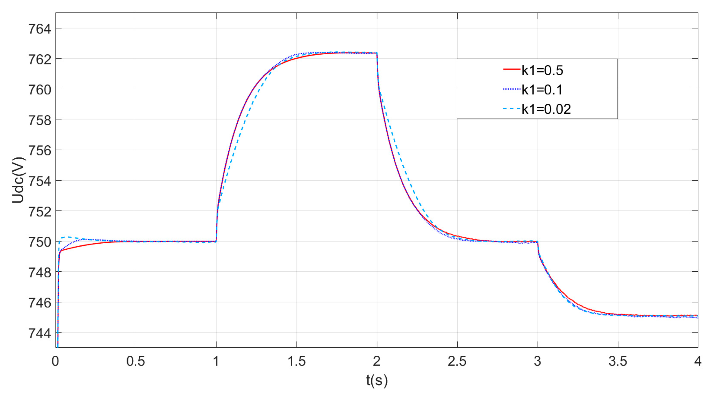
Figure 11 shows a simulation of DC voltage waveforms with different k1 parameters. The fastness of the system increases as the value of k1 increases. k1 is used as a correction coefficient whose value is related to the filtering parameters. It is not advisable to choose too small a size for k1 to avoid too much dependence on the value of k2.
6. Conclusions
In this paper, research was carried out on the problem of low inertia in the DC grid, which is very sensitive to power changes, including increases or decreases in distributed energy output. A virtual capacitance adaptive control method based on the voltage change rate is proposed and the strategy is improved. Through qualitative analysis, an exploration is conducted to study the impacts of the main parameters on DC voltage stability, aiming to provide virtual inertia support swiftly and flexibly for the DC grid. After theoretical and simulation analyses, the specific conclusions are as follows.
- (1)
- A virtual capacitance adaptive control strategy is proposed, which can adaptively change the virtual capacitance size during load fluctuation and provide flexible inertia support for the DC side by utilizing the converter of the energy storage system to quickly release and absorb energy, which improves the dynamic performance of the system.
- (2)
- A direct calculation of the virtual capacitance of this control strategy is proposed, and the effect of the virtual capacitance size on the system is qualitatively analyzed and simulated experimentally.
- (3)
- The strategy can effectively improve the dynamic performance of the DC distribution network when the parameters are within the appropriate range. Through the combination of the inverse tangent function and power function, it can effectively eliminate small disturbances and quickly respond to large disturbances, while maximizing the virtual inertia support.
- (4)
- By adopting this strategy on the battery side and combining it with the widespread application of droop control in the DC grid, it can effectively reduce the impact of the DC system on the AC grid, which has certain practical advantages.
Through the control method proposed in this paper, the voltage quality can be effectively improved and the system inertia can be enhanced, but the comprehensive consideration of system stability, rapidity, and storage charge state constraints is necessary to determine the optimal level of virtual inertia enhancement. Moreover, the performance of different source-side converters (with storage and without storage) in providing inertia needs to be further investigated.
Author Contributions
Conceptualization, W.L. and G.H.; methodology, W.L.; software, W.L.; validation, J.X., W.L. and G.H.; formal analysis, G.H.; investigation, G.H.; resources, W.L. data curation, W.L.; writing—original draft preparation, W.L.; writing—review and editing, W.L. and J.X.; visualization, G.H.; supervision, J.X.; project administration, J.X.; funding acquisition, J.X. All authors have read and agreed to the published version of the manuscript.
Funding
This research received no external funding.
Data Availability Statement
The data that support the findings of this study are available on request from the corresponding author, Liu W.X., upon reasonable request.
Conflicts of Interest
The authors declare no conflict of interest.
References
- Zeng, R.; Zhao, Y.M.; Zhao, B.; Zhong, Q.; Tong, Y.; Yuan, Z.; Yu, Z.; Zhao, Z.; Li, Y.; Chen, J. Aprospective look on research and application of DC powerdistribution technology. Proc. CSEE 2018, 38, 6791–6801. [Google Scholar]
- Wang, S.X.; Liu, Q.; Xue, S.M.; Yuan, D.; Wang, C.; Yang, J. Key technologies and prospect for coordinated control and protection in DC distribution system. Autom. Electr. Power Syst. 2019, 43, 23–30. [Google Scholar]
- Jiang, S.H.; Peng, K.; Xu, B.Y.; Zhang, X.; Liu, Y. Current situation and prospect of demonstration projects of DC distribution system. Electr. Power Autom. Equip. 2021, 41, 219–231. [Google Scholar]
- Liu, L.; Lin, G.; Jiao, S.Q.; An, B.; Li, Y.; Wang, Z.; Wang, S. Virtual DC generator control strategy and its dynamic analysis of DC charging station microgrid. Power Syst. Prot. Control 2020, 48, 28–35. [Google Scholar]
- Jami, M.; Shafiee, Q.; Gholami, M.; Bevrani, H. Control of a super-capacitor energy storage system to mimic inertia and transient response improvement of a direct current micro-grid. J. Energy Storage 2020, 32, 101788. [Google Scholar] [CrossRef]
- Sun, D.; Liu, H.; Gao, S.; Wu, L.; Song, P.; Wang, X. Comparison of Different Virtual Inertia Control Methods for Inverter-based Generators. J. Mod. Power Syst. Clean Energy 2020, 8, 768–777. [Google Scholar] [CrossRef]
- Wang, Q.G.; Zhou, Y.Y.; Liao, J.Q.; Zhou, N.C.; Zhang, X.F.; Zhang, Y. Review on Power Quality in DC Distribution Network. Autom. Electr. Power Syst. 2023, 47, 193–207. [Google Scholar]
- dos Santos Neto, P.J.; dos Santos Barros, T.A.; Silveira, J.P.C.; Ruppert Filho, E.; Vasquez, J.C.; Guerrero, J.M. Power management strategy based on virtual inertia for DC microgrids. IEEE Trans. Power Electron. 2020, 35, 12472–12485. [Google Scholar] [CrossRef]
- Cao, X.H.; Liu, Y.L.; Miao, S.H.; Li, L.; Liu, Z.; Li, Z. Research on virtual inertial control strategy of DC/DC converter in DC microgrid considering self-adaptive parameters. High Volt. Eng. 2020, 46, 1281–1290. [Google Scholar]
- Jiang, Z.H.; Liu, L.G.; Liu, Z.F. Research on Power Flow Control and the Voltage Fluctuation Characteristics of DC Distribution Networks Based on Different Control Strategies. Proc. CSEE 2016, 36, 919–926. [Google Scholar]
- Li, Y.; He, L.; Liu, F. Flexible voltage control strategy considering distributed energy storages for DC distribution network. IEEE Trans. Smart Grid 2019, 10, 163–172. [Google Scholar] [CrossRef]
- Li, Y.; Li, Y.L.; Li, S.; Shao, Z.; Chen, X. Power distribution and virtual inertia control of photovoltaic and hybrid energy storage system based on VSG. Electr. Power Autom. Equip. 2023, 43, 27–34. [Google Scholar]
- Wang, Y.; Hei, Y.; Fu, Y.; Shi, K. Adaptive Virtual Inertia Control of DC Distribution Network Based on Variable Droop Coefficient. Autom. Electr. Power Syst. 2017, 41, 116–124. [Google Scholar]
- Wang, H.; Zhao, S.Q.; Meng, J.H.; Wang, C.; Tian, Y. Adaptive Virtual Inertia Control for DC Microgrid Based on Droop Curve Intercept Adjustment. Autom. Electr. Power Syst. 2021, 45, 97–105. [Google Scholar]
- Li, C.; Zhang, X.; He, P.; Zhen, Z.; Zhao, K. Adaptive Droop Control of VSC-MTDC System Based on Virtual Inertia. Electronics 2023, 12, 2324. [Google Scholar] [CrossRef]
- Meng, J.H.; Zou, P.G.; Wang, Y.; Wang, C. Small-signalmodeling and parameter analysis of the DC microgrid based on flexible virtual inertia control. Trans. China Electrotech. Soc. 2019, 32, 2615–2626. [Google Scholar]
- Wu, W.H.; Chen, Y.D.; Luo, A.; Zhou, L.; Zhou, X.; Yang, L. A Virtual Inertia Control Strategy for Bidirectional Grid-connected Converters in DC Micro-grids. Proc. CSEE 2017, 37, 360–371. [Google Scholar]
- Chen, W.Q.; Xin, X.N.; Cheng, Z.P. Control of Grid-Connected of Photovoltaic System with Storage Based on Virtual Synchronous Generator. Trans. China Electrotech. Soc. 2018, 33, 538–545. [Google Scholar]
- Fu, Y.; Du, F.X.; Zhang, X.Y. Voltage hierarchical transient stability control of DC microgrid. Renew. Energy Resour. 2022, 40, 1105–1114. [Google Scholar]
- Chen, Y.Z.; Zhao, Q. Segmented Virtual Inertia Control Strategy for DC Distribution Networks. Electr. Autom. 2021, 43, 66–68. [Google Scholar]
- Zhu, X.R.; Cai, J.; Wang, Y.; Feng, Y.; Hu, X. Virtual Inertia Control of Wind-battery-based DC Micro-grid. Proc. CSEE 2016, 36, 49–58. [Google Scholar]
- Ma, W.Z.; Wang, L.B.; Wang, Y.S.; Wan, R.R.; Wang, X.R.; Wang, J.X. Hybrid energy storage power distribution and adaptive virtual inertia control considering SOC Power System Protection and Control. Power Syst. Prot. Control 2024, 52, 83–93. [Google Scholar]
- Zhang, X.Y.; Chen, L.W.; Fu, Y. Research on transient adaptive virtual inertia control strategy of DC microgrid and its parameter feasibility region. Electr. Power Autom. Equip. 2023, 43, 1–14. [Google Scholar]
- Fu, Y.; Huang, X.Y.; Xu, Y.; Bai, C.C. Controllable inertial control strategy of rotating motor in DC distribution network. Electr. Power Autom. Equip. 2018, 38, 32–38. [Google Scholar]
- Fu, Y.; Shao, X.Y.; Li, H. Transient Voltage Stability Control Strategy of DC Distribution Network. High Volt. Eng. 2021, 47, 1354–1362. [Google Scholar]
- Meng, J.H.; Song, M.Q.; Wang, Y. Multi-constraint Stable Operation Boundary of Grid-connected Voltage Source Converter of DC Microgrid with Virtual Capacitance Control. Autom. Electr. Power Syst. 2019, 43, 172–179. [Google Scholar]
Figure 1.
Schematic diagram of the four-terminal DC distribution network structure.
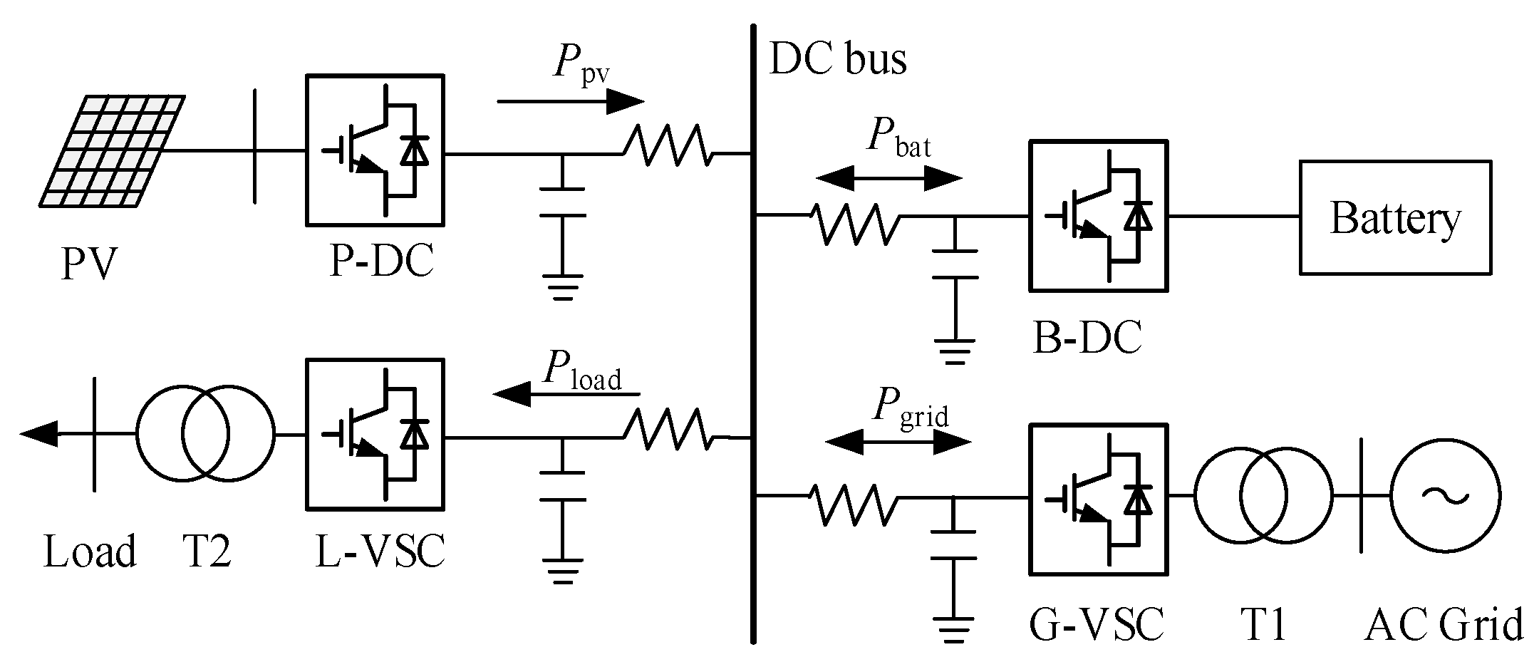
Figure 2.
DC side capacitance to increase virtual inertia.

Figure 3.
B-DC control block diagram using the improved virtual capacitor control strategy.
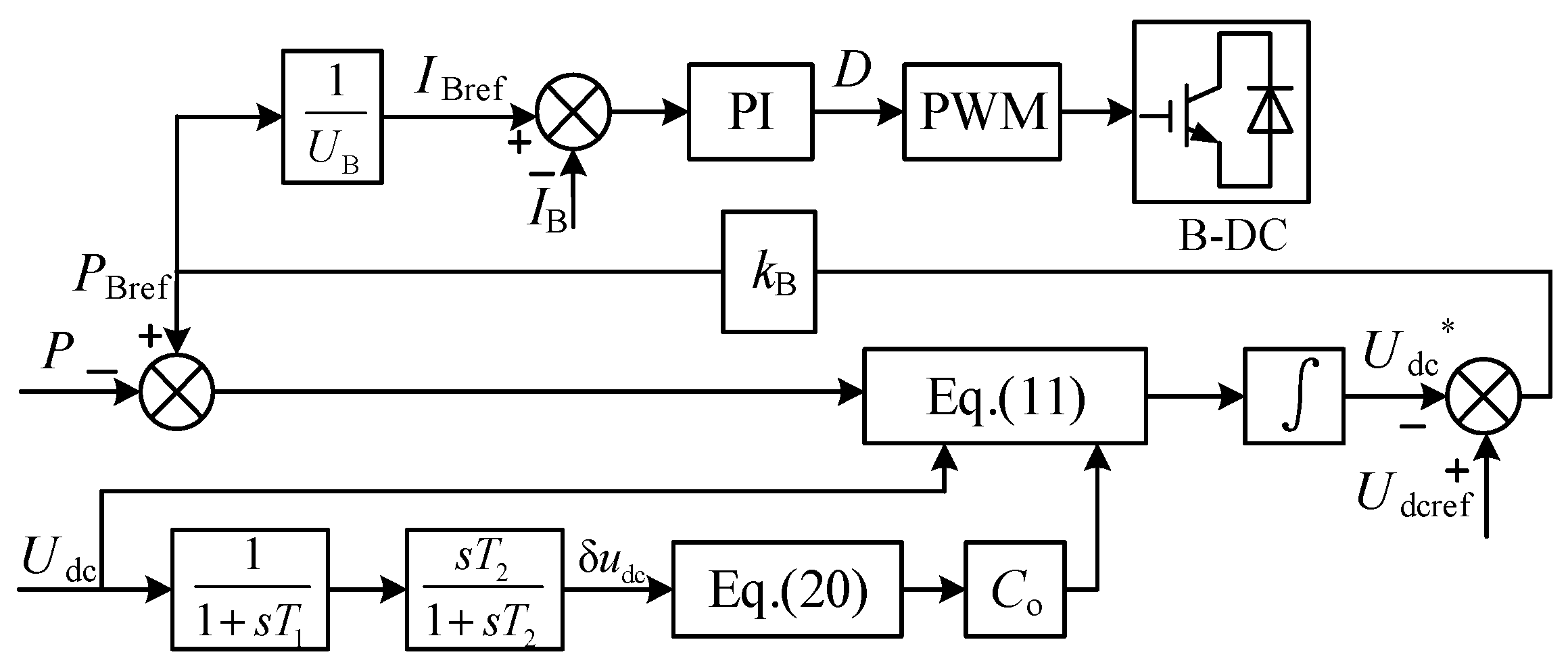
Figure 4.
Variation of virtual capacitance with k2.
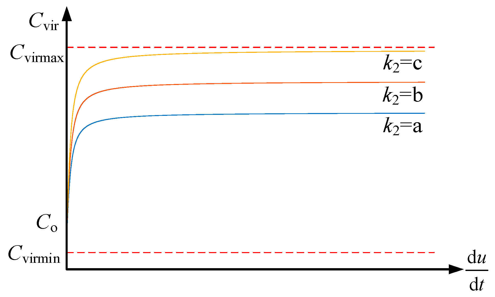
Figure 5.
Variation of virtual capacitance with k1.
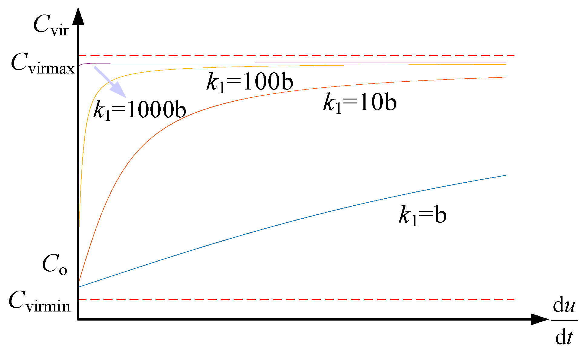
Figure 6.
Variation of virtual capacitance with k3.
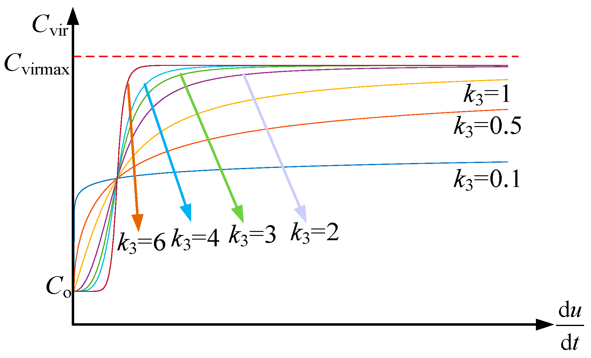
Figure 7.
DC voltage waveform with different controls.

Figure 8.
VSC power with different control strategies.

Figure 9.
DC voltage waveforms with different k2 parameters.

Figure 10.
DC voltage waveforms with different k3 parameters.
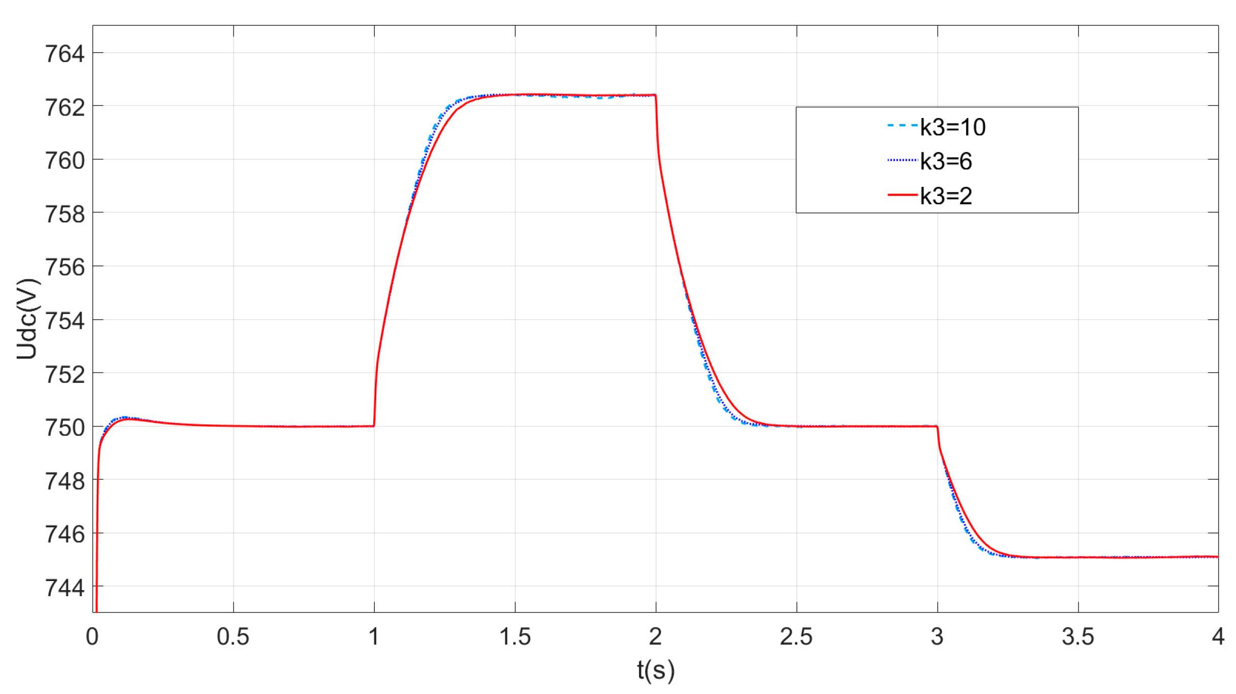
Figure 11.
DC voltage waveforms with different k1 parameters.

Table 1.
Parameters of traditional synchronous generators.
| Parameters | Unit | Value |
|---|---|---|
| UN | V | 380 |
| PN | kW | 30 |
| J | kg·m2 | 28.7 |
| ω | r/min | 1500 |
| HS | s | 7.9 |
Table 2.
Parameters of the DC grid.
| Parameters | Unit | Value |
|---|---|---|
| Udc | V | 750 |
| SNDC | kW | 30 |
| C | mF | 2 |
| Hdc | s | 0.012 |
Table 3.
Parameters of system components.
| Parameters | Value |
|---|---|
| UDC | 750 V |
| DC side capacitance | 2000 μF |
| G-VSC | Rated capacity of 30 kW |
| Energy storage | Battery voltage of 120 V, rated capacity of 100 A·h, rated capacity of 30 kW, SOC: 20~80% |
| Droop coefficient kB | −1/30,000 |
Disclaimer/Publisher’s Note: The statements, opinions and data contained in all publications are solely those of the individual author(s) and contributor(s) and not of MDPI and/or the editor(s). MDPI and/or the editor(s) disclaim responsibility for any injury to people or property resulting from any ideas, methods, instructions or products referred to in the content. |
© 2024 by the authors. Licensee MDPI, Basel, Switzerland. This article is an open access article distributed under the terms and conditions of the Creative Commons Attribution (CC BY) license (https://creativecommons.org/licenses/by/4.0/).
Share and Cite
MDPI and ACS Style
Xu, J.; Liu, W.; He, G. An Adaptive Virtual Inertial Control Strategy for DC Distribution Networks. Energies 2024, 17, 2401. https://doi.org/10.3390/en17102401
AMA Style
Xu J, Liu W, He G. An Adaptive Virtual Inertial Control Strategy for DC Distribution Networks. Energies. 2024; 17(10):2401. https://doi.org/10.3390/en17102401
Chicago/Turabian StyleXu, Junhua, Weixun Liu, and Guopeng He. 2024. "An Adaptive Virtual Inertial Control Strategy for DC Distribution Networks" Energies 17, no. 10: 2401. https://doi.org/10.3390/en17102401
Note that from the first issue of 2016, this journal uses article numbers instead of page numbers. See further details here.