
Electrofluorochromic Switching of Heat-Induced Cross-Linkable Multi-Styryl-Terminated Triphenylamine and Tetraphenylethylene Derivatives

Abstract
:1. Introduction
2. Results and Discussion
3. Materials and Methods
3.1. Materials and Instrumentation
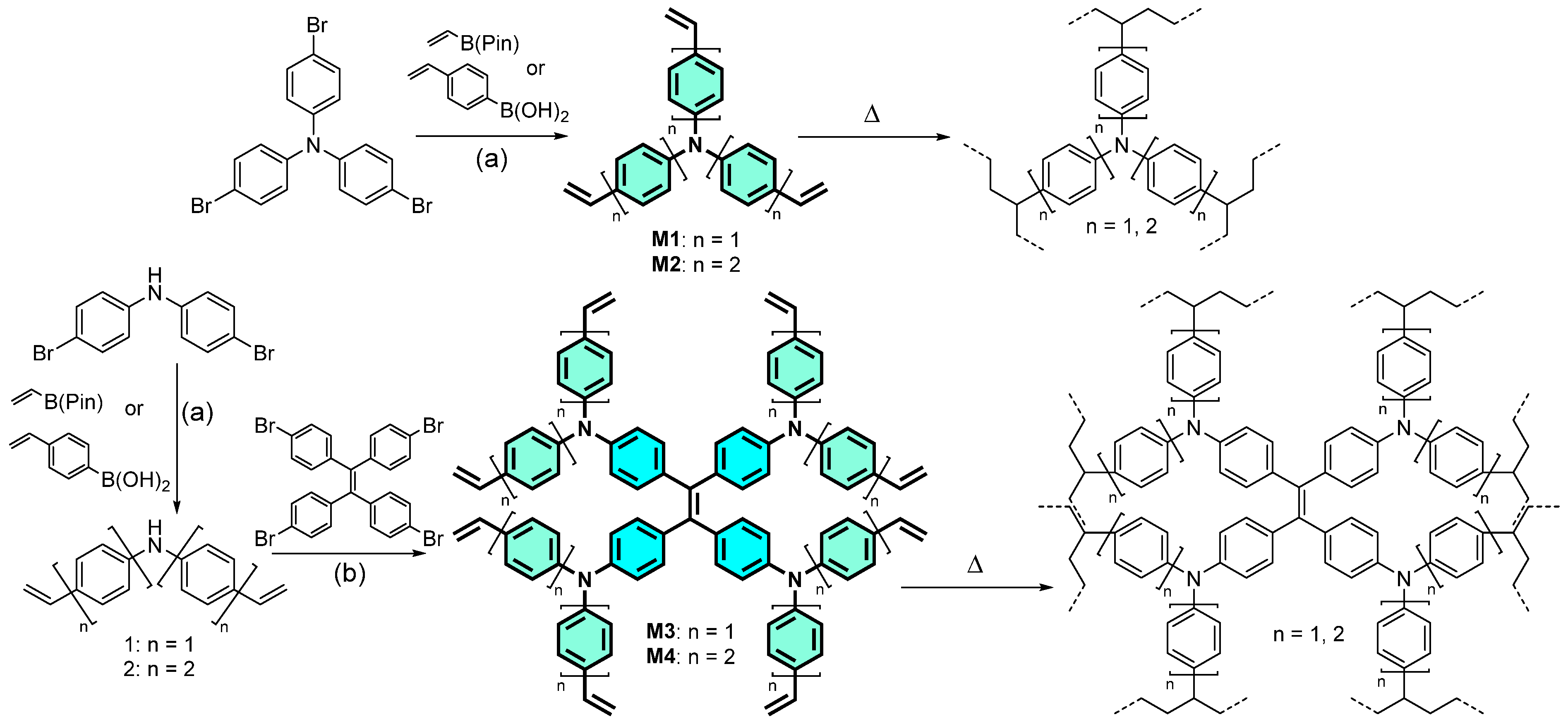
3.2. Synthesis of Materials
3.3. Cyclic Voltammetry
3.4. Fabrication of ECDs
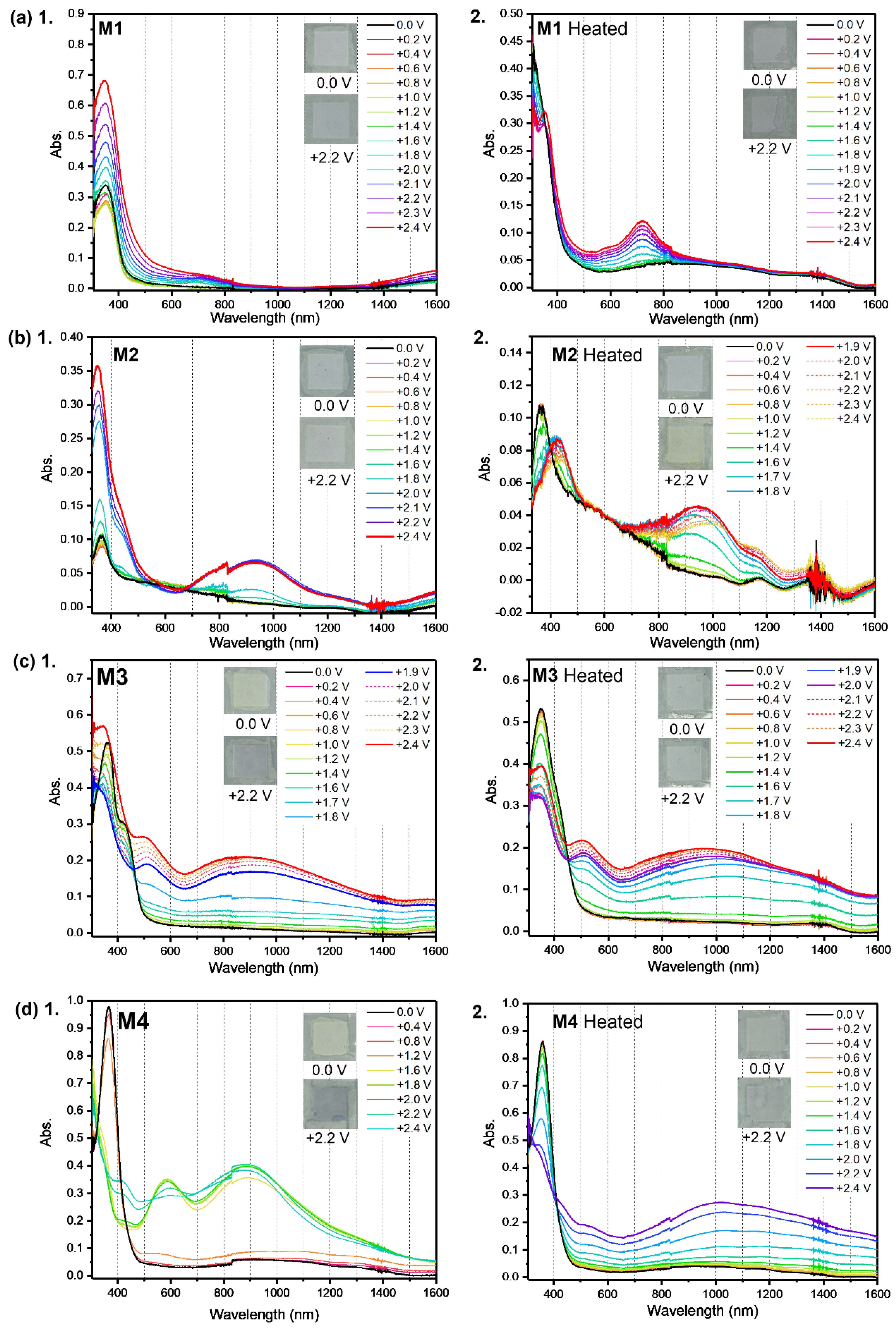
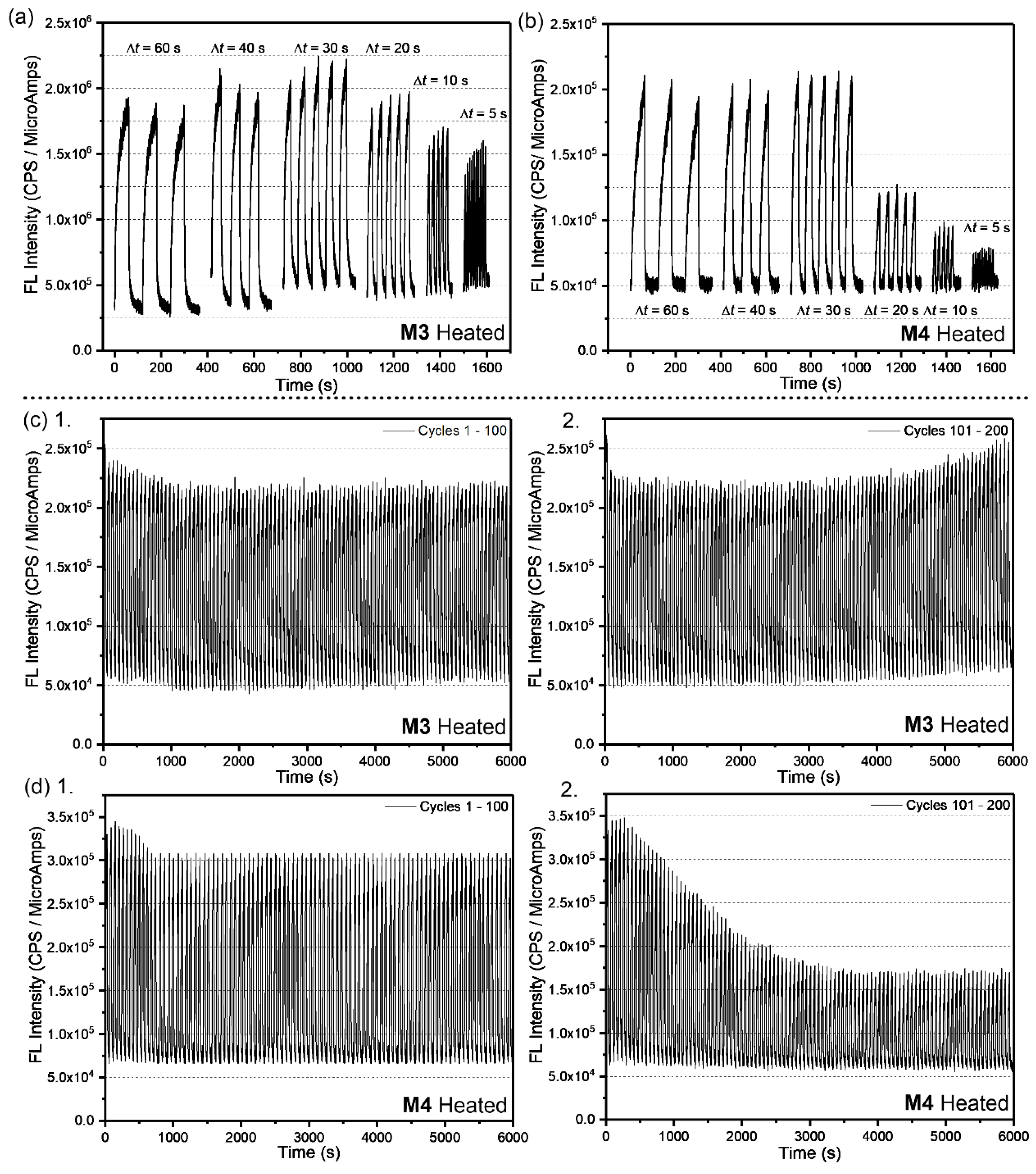
3.5. Spectroelectrochemistry and Chronoabsorptometry Studies
4. Conclusions
Supplementary Materials
Author Contributions
Funding
Institutional Review Board Statement
Informed Consent Statement
Data Availability Statement
Acknowledgments
Conflicts of Interest
References
- Chua, M.H.; Tang, T.; Ong, K.H.; Neo, W.T.; Xu, J.W. Introduction to Electrochromism. In Electrochromic Smart Materials: Fabrication and Applications; Xu, J.W., Chua, M.H., Shah, K.W., Eds.; The Royal Society of Chemistry: London, UK, 2019; pp. 1–21. [Google Scholar]
- Deb, S.K. A Novel Electrophotographic System. Appl. Opt. 1969, 8 (Suppl. S1), 192–195. [Google Scholar] [CrossRef]
- Granqvist, C.G. Electrochromic tungsten oxide films: Review of progress 1993–1998. Sol. Energy Mater. Sol. Cells 2000, 60, 201–262. [Google Scholar] [CrossRef]
- Niklasson, G.A.; Granqvist, C.G. Electrochromics for smart windows: Thin films of tungsten oxide and nickel oxide, and devices based on these. J. Mater. Chem. 2007, 17, 127–156. [Google Scholar] [CrossRef]
- Chernova, N.A.; Roppolo, M.; Dillon, A.C.; Whittingham, M.S. Layered vanadium and molybdenum oxides: Batteries and electrochromics. J. Mater. Chem. 2009, 19, 2526–2552. [Google Scholar] [CrossRef]
- Itaya, K.; Shibayama, K.; Akahoshi, H.; Toshima, S. Prussian-blue-modified electrodes: An application for a stable electrochromic display device. J. Appl. Phys. 1982, 53, 804–805. [Google Scholar] [CrossRef]
- Li, H.; Guarr, T.F. Reversible electrochromism in polymeric metal phthalocyanine thin films. J. Electroanal. Chem. Interfacial Electrochem. 1991, 297, 169–183. [Google Scholar] [CrossRef]
- Kulesza, P.J.; Miecznikowski, K.; Chojak, M.; Malik, M.A.; Zamponi, S.; Marassi, R. Electrochromic features of hybrid films composed of polyaniline and metal hexacyanoferrate. Electrochim. Acta 2001, 46, 4371–4378. [Google Scholar] [CrossRef]
- Zou, X.; Wang, Y.; Tan, Y.; Pan, J.; Niu, J.; Jia, C. Achieved RGBY Four Colors Changeable Electrochromic Pixel by Coelectrodeposition of Iron Hexacyanoferrate and Molybdate Hexacyanoferrate. ACS Appl. Mater. Interfaces 2020, 12, 29432–29442. [Google Scholar] [CrossRef]
- Shah, K.W.; Wang, S.-X.; Soo, D.X.Y.; Xu, J. Viologen-Based Electrochromic Materials: From Small Molecules, Polymers and Composites to Their Applications. Polymers 2019, 11, 1839. [Google Scholar] [CrossRef]
- Ye, W.; Guo, X.; Zhang, X.; Liu, P. Multicolored and high optical contrast flexible electrochromic devices based on viologen derivatives. Synth. Met. 2022, 287, 117076. [Google Scholar] [CrossRef]
- Lim, B.; Han, S.-Y.; Nah, Y.-C. Highly soluble diketopyrrolopyrrole-based donor-acceptor type small molecule for electrochromic applications. Org. Electron. 2018, 63, 23–28. [Google Scholar] [CrossRef]
- Muras, K.; Kubicki, M.; Wałęsa-Chorab, M. Benzochalcodiazole-based donor-acceptor-donor non-symmetric small molecules as dual-functioning electrochromic and electrofluorochromic materials. Dye Pigments 2023, 212, 111098. [Google Scholar] [CrossRef]
- Neo, W.T.; Ye, Q.; Chua, S.-J.; Xu, J. Conjugated polymer-based electrochromics: Materials, device fabrication and application prospects. J. Mater. Chem. C 2016, 4, 7364–7376. [Google Scholar] [CrossRef]
- Kim, J.; Rémond, M.; Kim, D.; Jang, H.; Kim, E. Electrochromic Conjugated Polymers for Multifunctional Smart Windows with Integrative Functionalities. Adv. Mater. Technol. 2020, 5, 1900890. [Google Scholar] [CrossRef]
- Vo, T.P.; Chua, M.H.; Ang, S.J.; Chin, K.L.O.; Soo, X.Y.D.; Png, Z.M.; Tam, T.L.D.; Zhu, Q.; Procter, D.J.; Xu, J. Pyrrolo[3,4-c]pyridine-1,2-dione: A new electron acceptor for electrochromic conjugated polymers. Polym. Chem. 2022, 13, 6512–6524. [Google Scholar] [CrossRef]
- Chua, M.H.; Toh, S.H.G.; Ong, P.J.; Png, Z.M.; Zhu, Q.; Xiong, S.; Xu, J. Towards modulating the colour hues of isoindigo-based electrochromic polymers through variation of thiophene-based donor groups. Polym. Chem. 2022, 13, 967–981. [Google Scholar] [CrossRef]
- Yan, S.; Zhang, L.; Lv, X.; Sun, J.; Zhang, Y.; Zhang, C. Black-to-Transmissive Electrochromism in π-Conjugated Polymer-Based Materials and Devices. Adv. Photonics Res. 2022, 3, 2000199. [Google Scholar] [CrossRef]
- Chua, M.H.; Zhu, Q.; Tang, T.; Shah, K.W.; Xu, J. Diversity of electron acceptor groups in donor–acceptor type electrochromic conjugated polymers. Sol. Energy Mater. Sol. Cells 2019, 197, 32–75. [Google Scholar] [CrossRef]
- Lv, X.; Li, W.; Ouyang, M.; Zhang, Y.; Wright, D.S.; Zhang, C. Polymeric electrochromic materials with donor–acceptor structures. J. Mater. Chem. C 2017, 5, 12–28. [Google Scholar] [CrossRef]
- Amb, C.M.; Dyer, A.L.; Reynolds, J.R. Navigating the Color Palette of Solution-Processable Electrochromic Polymers. Chem. Mater. 2011, 23, 397–415. [Google Scholar] [CrossRef]
- Corrente, G.A.; Beneduci, A. Overview on the Recent Progress on Electrofluorochromic Materials and Devices: A Critical Synopsis. Adv. Opt. Mater. 2020, 8, 2000887. [Google Scholar] [CrossRef]
- Nakamura, K.; Kanazawa, K.; Kobayashi, N. Electrochemical photoluminescence modulation of functional materials and their electrochemical devices. J. Photochem. Photobiol. C Photochem. Rev. 2022, 50, 100486. [Google Scholar] [CrossRef]
- Zhang, Y.; Berda, E.B.; Jia, X.; Lu, Z.; Zhu, M.; Chao, D. Electrochromic/Electrofluorochromic Supercapacitor Based on a Network Polysiloxane Bearing Oligoaniline and Cyanophenethylene Groups. ACS Appl. Polym. Mater. 2020, 2, 3024–3033. [Google Scholar] [CrossRef]
- Chua, M.H.; Chin, K.L.O.; Ang, S.J.; Soo, X.Y.D.; Png, Z.M.; Zhu, Q.; Xu, J. Aggregation Induced Emission (AIE)-Active Poly(acrylates) for Electrofluorochromic Detection of Nitroaromatic Compounds. ChemPhotoChem 2022, 6, e202200168. [Google Scholar] [CrossRef]
- Sun, J.; Chen, Y.; Liang, Z. Electroluminochromic Materials and Devices. Adv. Funct. Mater. 2016, 26, 2783–2799. [Google Scholar] [CrossRef]
- Zhuang, Y.; Guo, S.; Deng, Y.; Liu, S.; Zhao, Q. Electroluminochromic Materials and Devices Based on Metal Complexes. Chem.–Asian J. 2019, 14, 3791–3802. [Google Scholar] [CrossRef]
- Seddiki, I.; N’Diaye, B.I.; Skene, W.G. Survey of Recent Advances in Molecular Fluorophores, Unconjugated Polymers, and Emerging Functional Materials Designed for Electrofluorochromic Use. Molecules 2023, 28, 3225. [Google Scholar] [CrossRef]
- Suleymanov, A.A.; Ruggi, A.; Planes, O.M.; Chauvin, A.-S.; Scopelliti, R.; Fadaei Tirani, F.; Sienkiewicz, A.; Fabrizio, A.; Corminboeuf, C.; Severin, K. Highly Substituted Δ3-1,2,3-Triazolines: Solid-State Emitters with Electrofluorochromic Behavior. Chem.—Eur. J. 2019, 25, 6718–6721. [Google Scholar] [CrossRef]
- Chua, M.H.; Zhu, Q.; Shah, K.W.; Xu, J. Electroluminochromic Materials: From Molecules to Polymers. Polymers 2019, 11, 98. [Google Scholar] [CrossRef] [PubMed]
- Zhao, Z.; Zhang, H.; Lam, J.W.Y.; Tang, B.Z. Aggregation-Induced Emission: New Vistas at the Aggregate Level. Angew. Chem. Int. Ed. 2020, 59, 9888–9907. [Google Scholar] [CrossRef] [PubMed]
- Hong, Y.; Lam, J.W.Y.; Tang, B.Z. Aggregation-induced emission: Phenomenon, mechanism and applications. Chem. Commun. 2009, 29, 4332–4353. [Google Scholar] [CrossRef] [PubMed]
- Hong, Y.; Lam, J.W.Y.; Tang, B.Z. Aggregation-induced emission. Chem. Soc. Rev. 2011, 40, 5361–5388. [Google Scholar] [CrossRef]
- Mei, J.; Hong, Y.; Lam, J.W.Y.; Qin, A.; Tang, Y.; Tang, B.Z. Aggregation-Induced Emission: The Whole Is More Brilliant than the Parts. Adv. Mater. 2014, 26, 5429–5479. [Google Scholar] [CrossRef] [PubMed]
- Mei, J.; Leung, N.L.C.; Kwok, R.T.K.; Lam, J.W.Y.; Tang, B.Z. Aggregation-Induced Emission: Together We Shine, United We Soar! Chem. Rev. 2015, 115, 11718–11940. [Google Scholar] [CrossRef]
- Wang, H.; Zhao, E.; Lam, J.W.Y.; Tang, B.Z. AIE luminogens: Emission brightened by aggregation. Mater. Today 2015, 18, 365–377. [Google Scholar] [CrossRef]
- Liou, G.-S.; Yen, H.-J. Chapter 12—Electrofluorochromism in AIE luminogens. In Aggregation-Induced Emission (AIE); Xu, J., Chua, M.H., Tang, B.Z., Eds.; Elsevier: Amsterdam, The Netherlands, 2022; pp. 397–425. [Google Scholar]
- Cheng, S.-W.; Han, T.; Huang, T.-Y.; Tang, B.-Z.; Liou, G.-S. High-performance electrofluorochromic devices based on aromatic polyamides with AIE-active tetraphenylethene and electro-active triphenylamine moieties. Polym. Chem. 2018, 9, 4364–4373. [Google Scholar] [CrossRef]
- Sun, N.; Tian, X.; Hong, L.; Su, K.; Zhou, Z.; Jin, S.; Wang, D.; Zhao, X.; Zhou, H.; Chen, C. Highly stable and fast blue color/fluorescence dual-switching polymer realized through the introduction of ether linkage between tetraphenylethylene and triphenylamine units. Electrochim. Acta 2018, 284, 655–661. [Google Scholar] [CrossRef]
- Sun, N.; Su, K.; Zhou, Z.; Yu, Y.; Tian, X.; Wang, D.; Zhao, X.; Zhou, H.; Chen, C. AIE-Active Polyamide Containing Diphenylamine-TPE Moiety with Superior Electrofluorochromic Performance. ACS Appl. Mater. Interfaces 2018, 10, 16105–16112. [Google Scholar] [CrossRef] [PubMed]
- Sun, N.; Su, K.; Zhou, Z.; Tian, X.; Wang, D.; Vilbrandt, N.; Fery, A.; Lissel, F.; Zhao, X.; Chen, C. Synergistic effect between electroactive tetraphenyl-p-phenylenediamine and AIE-active tetraphenylethylene for highly integrated electrochromic/electrofluorochromic performances. J. Mater. Chem. C 2019, 7, 9308–9315. [Google Scholar] [CrossRef]
- Chen, S.-Y.; Chiu, Y.-W.; Liou, G.-S. Substituent effects of AIE-active α-cyanostilbene-containing triphenylamine derivatives on electrofluorochromic behavior. Nanoscale 2019, 11, 8597–8603. [Google Scholar] [CrossRef]
- Lin, H.-T.; Huang, C.-L.; Liou, G.-S. Design, Synthesis, and Electrofluorochromism of New Triphenylamine Derivatives with AIE-Active Pendent Groups. ACS Appl. Mater. Interfaces 2019, 11, 11684–11690. [Google Scholar] [CrossRef]
- Ling, H.; Liu, S.; Zheng, Z.; Yan, F. Organic Flexible Electronics. Small Methods 2018, 2, 1800070. [Google Scholar] [CrossRef]
- Sekitani, T.; Someya, T. Stretchable, Large-area Organic Electronics. Adv. Mater. 2010, 22, 2228–2246. [Google Scholar] [CrossRef] [PubMed]
- Guo, X.; Baumgarten, M.; Müllen, K. Designing π-conjugated polymers for organic electronics. Prog. Polym. Sci. 2013, 38, 1832–1908. [Google Scholar] [CrossRef]
- Abraham, S.; Mangalath, S.; Sasikumar, D.; Joseph, J. Transmissive-to-Black Electrochromic Devices Based on Cross-Linkable Tetraphenylethene-Diphenylamine Derivatives. Chem. Mater. 2017, 29, 9877–9881. [Google Scholar] [CrossRef]
- Lv, X.; Shao, M.; Zhu, X.; Xu, L.; Ouyang, M.; Zhou, C.; Dong, J.; Zhang, C. Thermally Cross-Linked Copolymer for Highly Transparent to Multicolor-Showing Electrochromic Materials. ACS Appl. Polym. Mater. 2023, 5, 3595–3603. [Google Scholar] [CrossRef]


| λabs Soln. (nm) a | λabs Film (nm) a | ε (M−1 cm−1) b | λonset Soln. (nm) c | Eg opt. (eV) d | λFL Soln. (nm) e | λFL Film (nm) e | ΦFL Soln. (%) f | ΦFL Solid (%) g | EHOMO (eV) h | ELUMO (eV) i | |
|---|---|---|---|---|---|---|---|---|---|---|---|
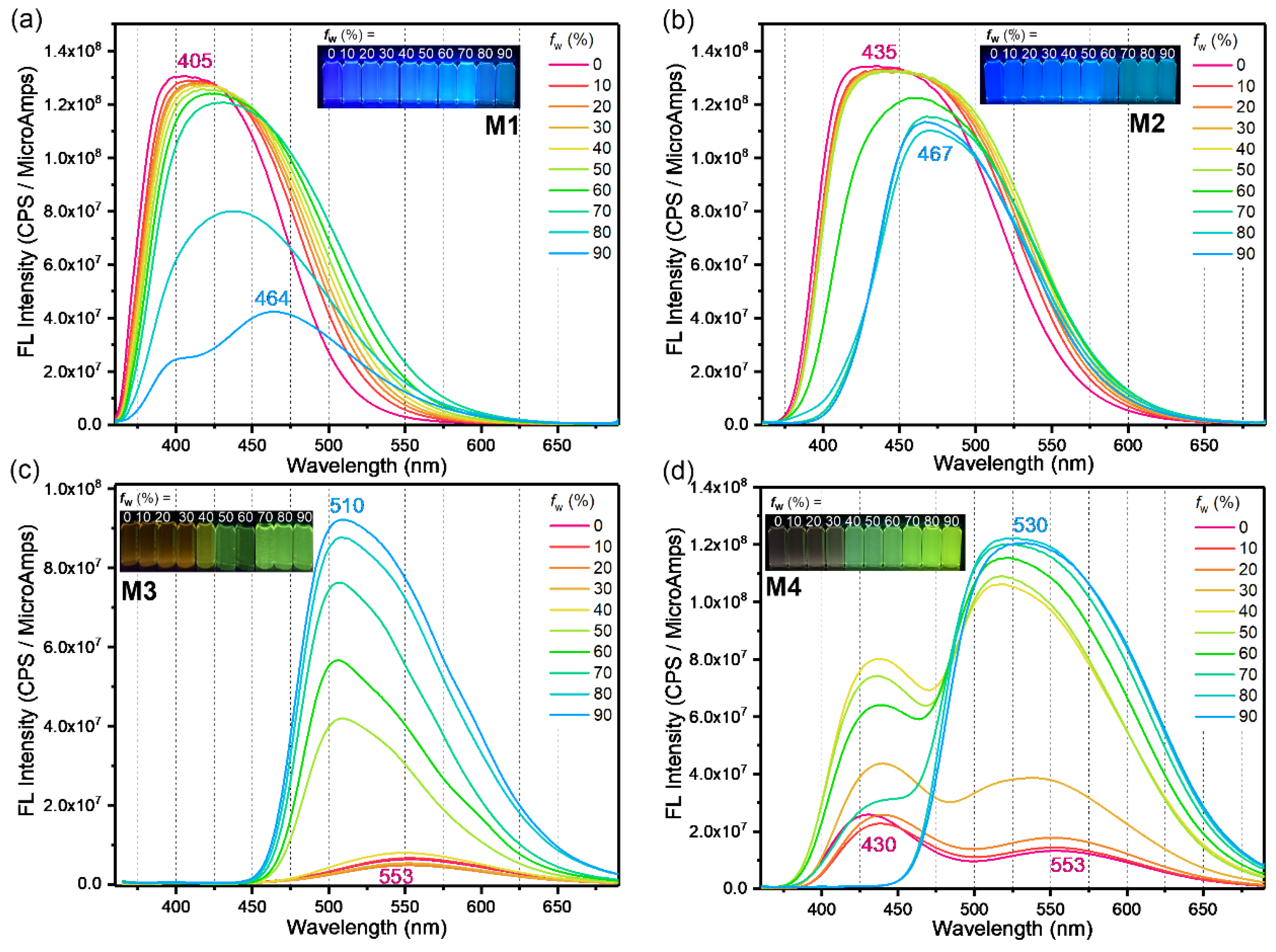
| M1 | 350 | 339 | 51 868 | 385 | 3.22 | 405 | 438 | 12.3 | 6.7 | −4.94 | −1.72 |
| M2 | 359 | 361 | 36 079 | 406 | 3.05 | 435 | 467 | 13.6 | 5.4 | −5.03 | −1.98 |
| M3 | 353 | 362 | 134 125 | 457 | 2.71 | 553 | 510 | 0.08 | 26.3 | −4.92 | −2.21 |
| M4 | 361 | 366 | 155 573 | 462 | 2.68 | 430, 553 | 533 | 0.15 | 26.6 | −4.97 | −2.29 |
Disclaimer/Publisher’s Note: The statements, opinions and data contained in all publications are solely those of the individual author(s) and contributor(s) and not of MDPI and/or the editor(s). MDPI and/or the editor(s) disclaim responsibility for any injury to people or property resulting from any ideas, methods, instructions or products referred to in the content. |
© 2024 by the authors. Licensee MDPI, Basel, Switzerland. This article is an open access article distributed under the terms and conditions of the Creative Commons Attribution (CC BY) license (https://creativecommons.org/licenses/by/4.0/).
Share and Cite
Chin, K.L.O.; Ong, P.J.; Zhu, Q.; Xu, J.; Chua, M.H. Electrofluorochromic Switching of Heat-Induced Cross-Linkable Multi-Styryl-Terminated Triphenylamine and Tetraphenylethylene Derivatives. Molecules 2024, 29, 2340. https://doi.org/10.3390/molecules29102340
Chin KLO, Ong PJ, Zhu Q, Xu J, Chua MH. Electrofluorochromic Switching of Heat-Induced Cross-Linkable Multi-Styryl-Terminated Triphenylamine and Tetraphenylethylene Derivatives. Molecules. 2024; 29(10):2340. https://doi.org/10.3390/molecules29102340
Chicago/Turabian StyleChin, Kang Le Osmund, Pin Jin Ong, Qiang Zhu, Jianwei Xu, and Ming Hui Chua. 2024. "Electrofluorochromic Switching of Heat-Induced Cross-Linkable Multi-Styryl-Terminated Triphenylamine and Tetraphenylethylene Derivatives" Molecules 29, no. 10: 2340. https://doi.org/10.3390/molecules29102340