
Aligning Liquid Crystal Materials through Nanoparticles: A Review of Recent Progress


Department of Physics, Aligarh Muslim University, Aligarh 202002, India
*
Author to whom correspondence should be addressed.
Liquids 2022, 2(2), 50-71; https://doi.org/10.3390/liquids2020005
Submission received: 2 April 2022
/
Revised: 1 May 2022
/
Accepted: 4 May 2022
/
Published: 18 June 2022
(This article belongs to the Collection Feature Papers in Solutions and Liquid Mixtures Research)
Abstract
:Liquid crystals (LCs) have become indispensable materials in everyday life, with their applications ranging from high-resolution television displays to being a part of sophisticated and modern equipment for telecommunications and sensing purposes. Various important features of LC-based devices such as their response time, driving voltage, contrast ratio and brightness are controlled by the uniform alignment of the constituting molecules along the substrate surface. This alignment control can be achieved through various mechanical and non-mechanical techniques. Nanoparticles (NPs), which have become an underbelly of the latest technological developments, can also be incorporated into these tunable materials in order to achieve the desired alignment in them. The present review highlights the advantages of NPs -induced alignment technique over the other contemporary techniques available for aligning LCs. The NPs-induced alignment process is found to be cost-effective and reliable, and it does not require extreme physical conditions such as a low pressure for its operation. This alignment process enables manufacturers to effectively control the pretilt angle of the LC molecules by simply varying the concentration of the doped NPs in the host LC matrix. Furthermore, the alignment behavior in LCs is found to be a function of shape, size, concentration and solubility of the doped NPs in these materials. At the end, this review focuses on the methodology of developing new innovative devices based on this alignment process. With the fabrication of new NPs of different morphologies in recent times, the horizon of the LC nanoscience field is continuously increasing, thus paving way for new devices capitalizing on this alignment technique.
1. Introduction
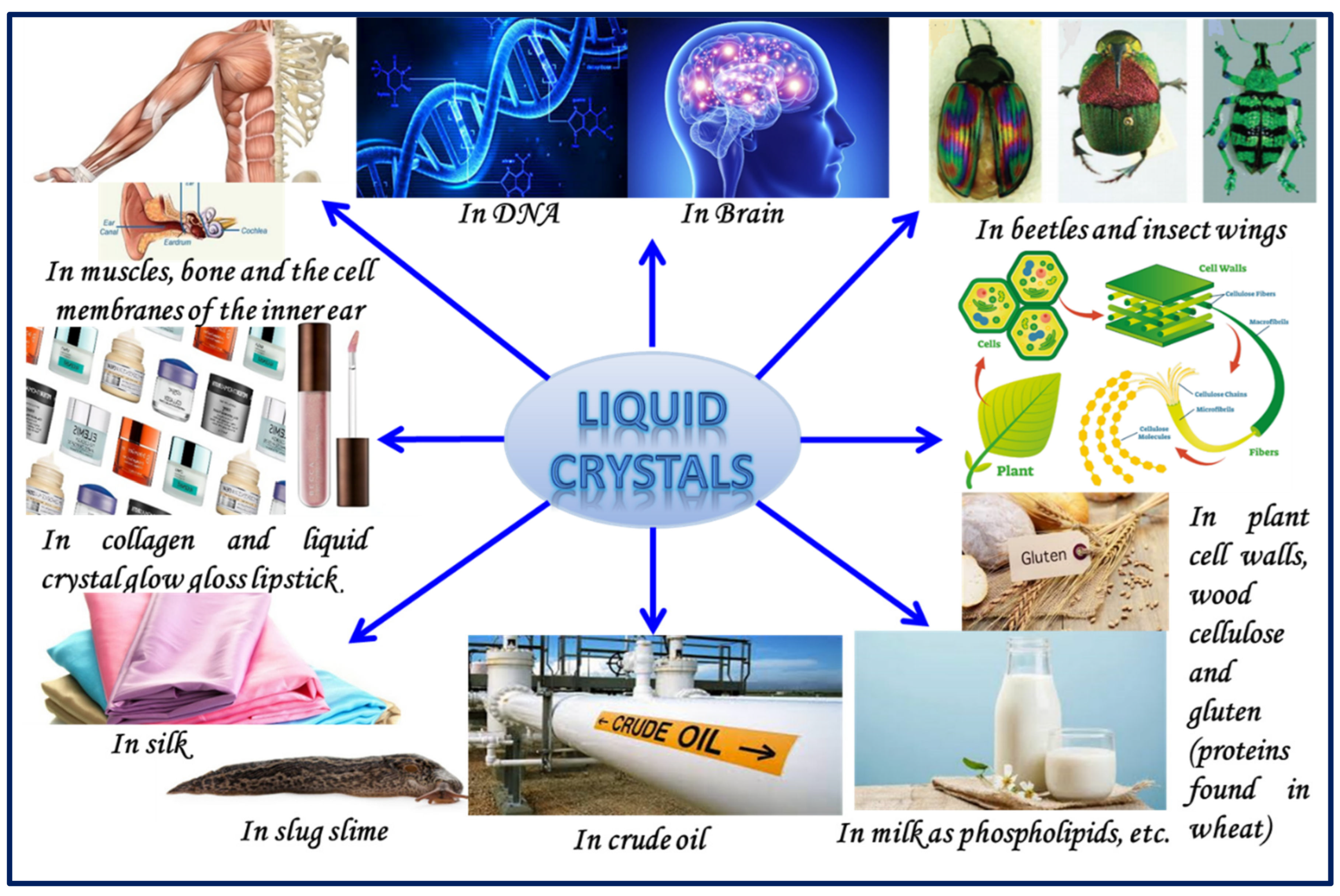
Liquid crystals (LCs), intermediate phases with a tendency to flow like liquids but having optical properties similar to solids, have unmasked extensive research in various fields due to their self-organizational nature and their ability to form structures of different types [1,2,3,4,5]. The relevance of these materials, discovered in 1888, is highlighted in various displays and photonic and other high-tech devices due to their tunable electro-optical nature [6,7,8]. LCs are ubiquitous materials, if we know where to look. They are found in gluten, milk, phospholipids, lipstick, cell membranes of the inner ear, crude oil, insect wings, snail slime, mineral slurries, DNA, Bose–Einstein condensates, etc. [9,10]. Figure 1 shows a glimpse of the presence of LCs around us.
The orientational dynamics of these materials are influenced by the presence of external perturbing fields, which in turn affects their dielectric behavior as well. The demand for tunable and reconfigurable materials in the micro- and millimeter wavelength regions has placed the spotlight on LCs in recent years [11]. The canvas of the LC field continues to increase manifold due to the mobile and anisotropic behavior of these materials.
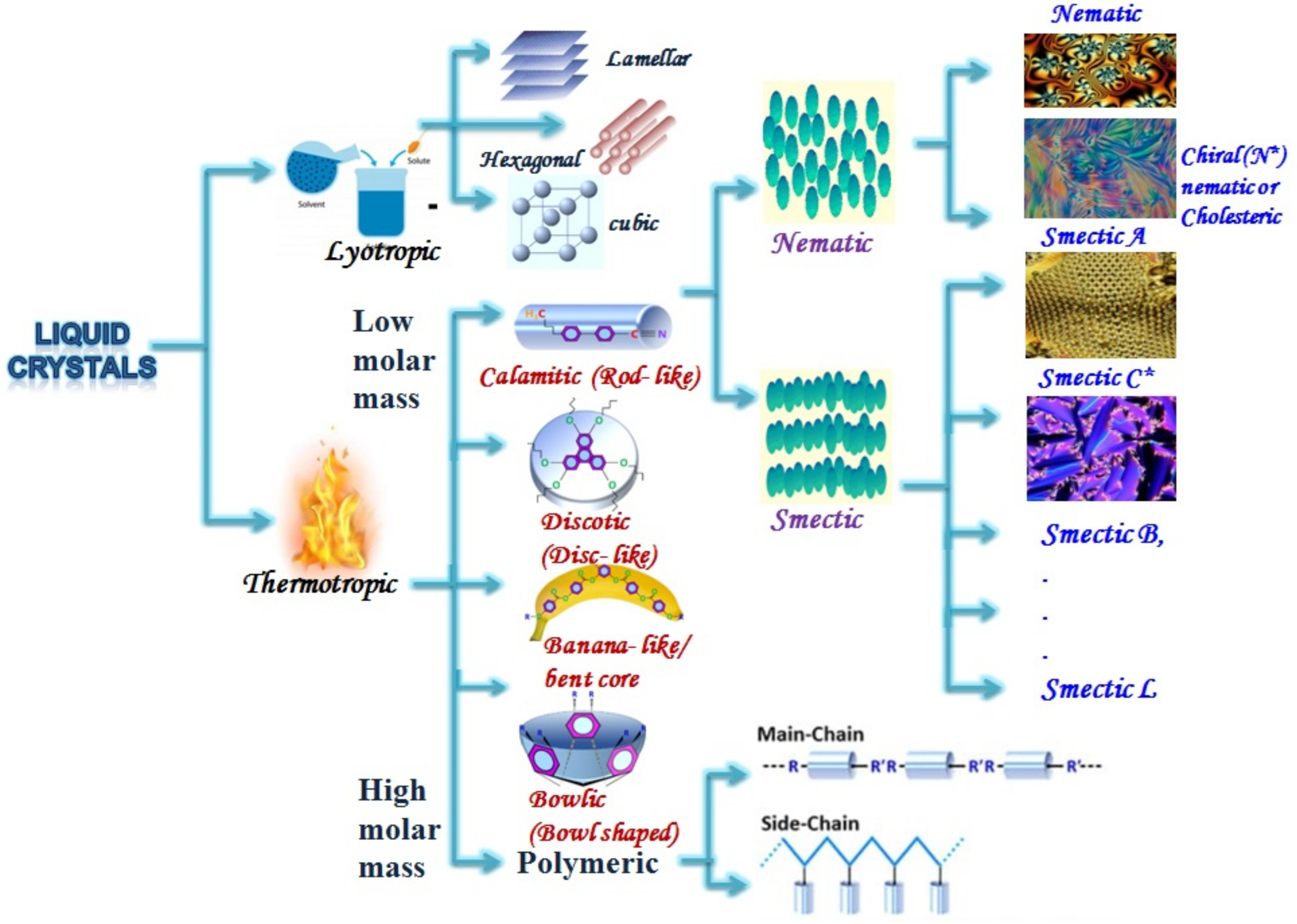
LCs can be broadly divided into two groups, thermotropic and lyotropic, based on the different physical attributes which affect their phase transitions [12]. The phase transitions in thermotropic LCs are a function of the temperature only, whereas in lyotropic LCs, these transitions are governed by the amphiphilic mesogenic concentration in a suitable solvent under ambient temperature and pressure [13]. Thermotropic LCs are enormous in number and are extensively used in various applications due to the wide variety of substituents available for connecting functional groups at the terminal and core positions in them [14,15,16,17]. Meanwhile, lyotropic LCs commonly exhibit lamellar, cubic and hexagonal phase structures [18,19,20,21]. The lamellar phase consists of a layered arrangement in which water is sandwiched between the amphiphiles in such a way that the hydrophilic part of it is in contact with the water but the hydrocarbon part is directed away from it [19]. Similarly, in the cubic phase, the mesogenic arrangement is in the form of a sphere with polar heads lying on the surface of it and the hydrophobic part filling up its volume. The hexagonal phase, on the other hand, consists of amphiphilic molecules arranged in the form of infinite cylindrical structures on a hexagonal lattice. The lattice constant of all these lyotropic mesophases is of the order of a few nanometers which enables them to be used for fabricating various soft materials such as biomolecules, emulsions etc.
Thermotropic LCs can be subcategorized into discotic, calamitic and banana-shaped LCs [1,2,22,23,24,25]. Discotic LCs are disc-shaped molecules composed of aromatic or phenyl rings encapsulated by flexible hydrocarbon chains [22,23,24]. The arrangement of these molecules is in the form of a stack which causes an overlap of π* orbital, thereby resulting in conductivity due to the electron transfer among them [23]. Calamitic mesophases, on the other hand, have rod-shaped molecules which are characterized by a rigid polarizable core with flexible substituents on either side. Calamitic LCs can be further subdivided into nematic, smectic and cholesteric LCs [1]. The simplest LC phase which is characterized by only the long-range orientational order with no positional order is the nematic LC (NLC) phase [13,26]. The orientational ability of the director of NLCs under the external applied electric as well as magnetic field coupled with other interesting features such as low power consumption and a large cell gap tolerance gives them tremendous scope in various display applications [12,26,27,28,29]. Besides their cost-effective nature, these materials exhibit a high switching time and have low viscosity as well. In contrast to nematics, smectic LCs exhibit periodicity in one direction of space along with the orientational order [2,30,31,32]. This positional ordering in one dimension causes molecules to arrange themselves in well-defined layers which are capable of sliding over one another. This imparts fluid behavior to this system and these materials generally have higher viscosity than NLCs. Another fascinating subgroup of the LC family is the cholesteric LC (CLC) phase, which is obtained by the introduction of a chiral molecule in the achiral NLC phases. Despite being symmetric, CLCs differ from nematics in the context that the director of these materials moves uniformly in the medium, thereby paving the way for a helical structure [33,34]. CLCs have registered their foothold in various technological applications as their unique optical properties can be tuned or refined easily by altering their pitch length [35,36]. Scientifically, the position and concentration of chiral molecules in these CLCs control the birefringence, viscosity and anisotropic behavior, thus leading to a profound impact on their pitch length [37]. On the contrary, when chirality is induced in smectic phases with tilted structures, they start to exhibit spontaneous polarization and piezoelectric properties [1,2]. Such chiral smectic phases are termed ferroelectric LCs (FLCs) and are characterized by a spatially modulated layered structure with the molecular director precessing helicoidally while moving from one layer to another [38,39,40]. These FLCs have unleashed their prominence in modern technological applications due to their bistable nature and faster switching speed [41]. A description of this classification is schematically presented in Figure 2.
LCs have been ushered into various scientific areas of research due to their self-organizational nature and ability to easily respond to external applied fields. Thermotropic LCs having polar substituents such as –NCS, –F and –CN at one end also serve as excellent lubricating agents [42]. This lubrication effect is due to the ordered structure of LCs which enables the two contacting metallic surfaces to easily glide over one another and thus reduce the energy loss due to friction. In earlier times, NLCs were the underbelly of display applications due to their simple molecular alignment and ability to operate even at lower voltages [12,43]. Afterwards, many NLC mixtures with large values of dielectric anisotropy and birefringence were synthesized in order to remove the constraint of the poor switching time which plagued these materials [44]. Apart from displays and digital calculators, nematics are also used for the study of malignant and non-malignant tissues in human beings for the treatment of cancer as well [45]. While the earlier use of cholesterics was restricted to display applications and temperature sensors, currently, their tunable nature is put to effective use in mirrorless lasing action [46,47,48]. This application is harnessed by the presence of a selective reflection band in these materials. Furthermore, the reflection band can be expanded or allowed to dwindle by the action of the external applied field, thereby paving the way for its usage in tunable dye lasers [46]. The property of CLCs to selectively reflect light of a particular wavelength makes them a useful candidate for the fabrication of diffraction gratings as well.
In recent times, lyotropic LCs have unleashed tremendous curiosity among various research groups due to their excellent potential in drug delivery systems and in colloidal science [18,19,49]. Apart from their biodegradable and non-toxic nature, lyotropic systems are endowed with the property to assimilate different types of amphiphilic, hydrophobic and hydrophilic additives [50]. The hexagonal LC phase (a subtype of the lyotropic LC phase) is often employed for the transport of pharmaceutical compounds and important biomolecules such as peptides, proteins and nucleic acids [19,51]. Even DNA macromolecules, which are considered as the seat of genetic information in human beings, form lyotropic LC phases when dispersed in water [50]. The presence of a lyotropic mesophase is not restricted to organic molecules only but is also widespread in the suspensions formed by dispersing inorganic minerals such as clay in an aqueous medium [52]. Such phases are also produced by the mixing of proper concentrations of polymers in various isotropic solvents. For example, the incorporation of aramid polymers in concentrated sulfuric acid yields a heat-resistant synthetic fiber with high tensile strength [1,50]. This material, named as Kevlar, exhibits liquid crystalline behavior and has wide ranging applications from bicycle tires to bulletproof vests [53].
Nanomaterials with dimensions in the range from 1 to 100 nm have become the backbone for industrial development due to their size-dependent optical, magnetic and electronic properties [54,55,56,57]. The unique properties of nanostructured materials can be further diversified by incorporating them into tunable anisotropic materials such as LCs. The coupling of the long-range orientational order in LCs with the intrinsic properties of doped nanoparticles (NPs) has a substantial impact on the overall properties of newly formed composites [58]. Technological advances require novel materials with refined characteristics, and the combination of NPs with LCs focuses on the development of such materials for various applications. This combination may cause an increase in the contrast ratio along with dielectric and optical anisotropy, improve the switching time of the composite system and even induce a non-volatile memory in it [59,60]. Furthermore, the recent developments in the LC nanoscience field include the enhancement of the physical and electro-optical properties of many materials which has profound applications in the field of photonics and biotechnology [61,62,63]. For example, doping of the optimum amount of silver NPs into a NLC 4-(trans-4′-nhexylcyclohexyl)-isothiocyanatobenzene (commonly known as 6CHBT) causes a decrease in the response time and significantly improves the switching time of the doped samples [61]. These results will be fruitful for the improvement of the spectral, polarizing and guiding properties of photonic crystal fibers infiltrated with LCs which are useful for telecommunication and sensing purposes [62]. Similarly, doping of semiconducting NPs such as quantum dots (QDs) in LCs may open new doors of applications in the fields of optoelectronics, drug delivery mechanisms and biochemical sensors [64,65,66]. QDs are electron-deficient species and are capable of forming a link between polymer and organic substituents, when doped in hybrid solar cells [64]. This blend formation by QDs considerably improves the charge transport mechanism in these solar cells, thereby overcoming the poor conductivity shortcoming associated with the constituent polymer. It is also observed that the doping of these semiconductor NPs in columnar LCs results in doubling of the DC conductivity in them due to the same blend formation in these QD-LC composites.
The alignment of LC molecules over a suitable substrate is essential for their applications in different fields such as sensing, displays, photonics and photovoltaics [67,68,69,70,71,72,73,74,75,76,77,78]. In particular, the orientation of the LC director, pretilt angle and surface anchoring strength of the constituent molecules collectively help in studying the alignment properties of mesogens [69,79]. Various important features of a LC display such as its brightness, contrast ratio and response time are influenced by the alignment of these phases between the substrates [80,81,82,83]. The response time and driving voltage of these displays are precisely controlled by the pretilt angle of the LC molecules. Variations in the pretilt angle even of the order of 0.2° may cause unevenness in the visibility [69]. Generally, a LC alignment with a pretilt angle of 1° or less is usually preferred in order to obtain a high contrast ratio in displays [69,84]. Similarly, spatial variation in the pretilt angle can serve the fruitful purpose of obtaining low-power-consuming tunable lenses composed of LCs. Furthermore, in order to achieve a wider viewing angle and reduce the problem of image sticking in displays, in-depth study of the surface anchoring strength of LC molecules is important. The surface anchoring strength gives an estimate of the energy required to change the orientation of the director of LCs from its initial anchoring position [85]. Moreover, it is an important parameter to understand the interfacial interaction of LCs at different surfaces [86,87,88,89]. In earlier times, strong anchoring characteristics were required to reduce the problem of image sticking in LC-based displays [69]. However, in recent years, many devices involving weaker strength characteristics have also been developed. Therefore, the alignment control of LC molecules involves the appropriate choice of pretilt angle, director direction and surface anchoring strength in order to achieve the desired electro-optical behavior in various applications [88].
2. Ways to Align Liquid Crystal Materials
There are three possible alignments of LCs over the substrate: homogeneous (also known as planar), homeotropic (also known as vertical) and hybrid [67]. Homogeneous alignment is achieved when the long axis of LC molecules is oriented along the substrate surface, whereas in homeotropic alignment, the LC director lies perpendicular to the substrate. Alternatively, the angle between the substrate and the LC director, i.e., the pretilt angle varies between 0° and 90° in the case of a tilted LC alignment and is 0° and 90° for planar and homeotropic alignment respectively. In the case of hybrid alignment, the molecules are parallel to one substrate and perpendicular to another, i.e., hybrid alignment is a mixture of planer and vertical alignment configurations. A schematic representation of vertical, planar and hybrid alignment is exhibited in Figure 3.
One of the persistent problems in the LC field is to obtain a stable pretilt angle of the molecular director with respect to the substrate surface. In order to achieve better optimization of LC-based devices, pretilt control is necessary. For example, a LC-based polymer retardation film can be fabricated only if a large value of the pretilt angle is made available. Many LC applications such as bistable displays and tunable lenses have a prerequisite of having a pretilt angle from 10° to 80° [90]. Such a broad range of pretilt angles can be achieved by the mixing of vertical- and planar-aligned materials.
Traditional alignment methods involve unidirectional rubbing of a velvet or nylon cloth on the lower and upper solid substrates coated with a thin layer of polyimide (PI), in order to achieve the desired homogeneous alignment [67,76,91,92,93,94,95,96,97,98]. The rubbing creates an array of microgrooves in the thin PI layers, and the LC molecules are aligned along these grooves [76]. For substrates that are rubbed in more than one direction, the pretilt angle is determined by the last rubbing direction [99]. The rubbing process has proved to be beneficial for the mass production of LC displays with good electro-optical characteristics. However, this prevailing technique for aligning LC molecules suffers from numerous disadvantages [67]. It often causes surface deterioration and stimulates the generation of immobile radicals and ions on the sample substrates. Additionally, this rubbing technique does not yield fruitful results in the case of multidomain alignment requirements. Due to its innumerable drawbacks, the rubbing technique was later replaced by another homogeneous alignment technique involving the oblique evaporation of materials such as silicon monoxide or gold on the sample substrates [100,101,102,103,104,105,106,107,108,109,110]. LC devices fabricated through this technique are found to exhibit better electro-optical characteristics as compared to those fabricated through the rubbing process [100]. This oblique evaporation process requires an extremely low pressure below 10−5 Torr and creates a thin film of a thickness around 100 Å in a specific direction. This technique is beneficial for LC display devices in certain ways. Apart from exhibiting a strong and stable alignment, it can also withstand high temperature (of around 500 °C) during the glass frit sealing of the substrate plates [111]. Moreover, the pretilt angle of LC molecules is found to be influenced by the angle between the evaporation beam of silicon monoxide and normal to the substrate [112]. This allows the pretilt bias angle to be easily manipulated by the variations in the incidence angle of the evaporation beam. Later, Minhua and his research group further analyzed the possibility of achieving a tilted or homeotropic alignment of LCs using the oblique evaporation of the silicon dioxide layer [75]. They concluded that the single evaporation of the silicon dioxide layer results in LCs being aligned homeotropically or homogenously depending on whether the dielectric anisotropy of the material is negative or positive, respectively.
Research groups in recent years have switched to non-mechanical alignment methods including photoalignment techniques and NP-induced alignment [113,114,115,116,117,118,119,120,121,122,123,124,125,126].
A step-by-step procedure to obtain a one-dimensional photo-polymerized material [76]. In the photoalignment technique, the substrate is first coated with a photoreactive chemical and is then exposed to a polarized beam of light [113,114,115,116,117,118,119,120,121,122,123,124,125,126,127,128,129,130,131,132]. The beam irradiation on this photosensitive material results in the E/Z or trans/cis photoisomerization of the monolayer on the substrate surface and therefore results in switching of NLC molecules between homogeneous and homeotropic modes [113]. Effectively, this photosensitive material or its photoproducts formed as a result of beam irradiation are responsible for aligning the LC molecules [114]. This technique was first used by Ichimura et al. on quartz substrates treated with an azobenzene compound which served the purpose of a command surface [116]. The orientation of the chemically coated substrate with respect to the polarized beam causes the alignment of the LC molecules along the desired pretilt angle. Apart from the oblique incidence of the polarized beam of light, the pretilt angle in this alignment process is also influenced by the bulkiness, length and polarity of the substituents present in the aligning material. Moreover, it is also reported that the pretilt angle profile can be effectively controlled by changes in the total dose of the irradiated beam on the cross-linked polymer materials. The pretilt angle is found to increase with the increase in the cumulative doses of the incident beam, and this pretilt control is stable against external environmental conditions such as temperature and pressure [117]. This confirms that this technique helps in achieving a controllable anchoring energy by varying the doses of the irradiation on the aligning material [118]. Furthermore, it is more beneficial than the conventional rubbing technique due to its non-contact nature, thus allowing easy alignment of LC molecules even in mechanically inaccessible regions [67]. This technique has an upper hand in aligning large-sized substrates for LC displays and is also beneficial in achieving domain-divided pixels. In contrast to the rubbing mechanism, there is feeble accumulation of static charges on the substrate which could destroy the functioning of diodes and transistors within the LC displays [115]. Apart from displays, photoalignment of LCs offers vast potential in various telecommunication, photonic and thin-film electronic devices as well [113,117,119,127,128,129,130,131,132].
An important method to achieve homeotropic alignment in an LC cell without using vertical alignment layers is the NP-induced alignment technique [133,134,135,136,137]. This technique is used to generate various pretilt angles by doping different concentrations of NPs in a planar-aligned LC material [135]. Moreover, this method of aligning LC materials has been readily adopted by display manufacturers as it utilizes the conventional PI alignment layer and other traditional facilities only. It undoes the requirement of extreme physical condition such as a low pressure which is required in the alignment process of the oblique evaporation of silicon monoxide. The alignment behavior of NP-doped LC systems is found to depend on the order parameter, the concentration of NPs in the host and its physical conditions [136]. This technique is especially suitable for fabricating flexible displays at a low temperature, thereby omitting drawbacks which are generally associated with a high-temperature fabrication process [137]. It has also opened up the possibility of using alignment-free LC displays along with the added benefit of utilizing the intrinsic electronic properties of the doped NPs [136].
3. Nanoparticle-Induced Alignment
The combination of NPs and LCs has gained extensive pace in recent years due to their interesting guest–host interaction as well as high surface-to-volume ratio [138,139]. It is well established that the incorporation of NPs into LCs can perturb their self-assembled nature, produce various structural defects in these phases and even break their continuous rotational symmetry [140,141]. Apart from exhibiting various electro-optical characteristics such as frequency modulation response, low threshold voltage and memory effect, the doping of NPs into LCs can severely affect the alignment properties of the host as well [134]. The unique shape- and size-dependent behavior of nanoscaled particles can be effectively capitalized to analyze different alignment effects in LC hosts [142]. This alignment behavior is majorly affected by changes in the concentration of the doped NPs and yields results which are suitable for flexible plastic displays [141]. Different research groups have observed perfect homogeneous and homeotropic alignment in LCs by dispersing NPs of different shapes in them. While the incorporation of spherical NPs in various LCs induced homeotropic alignment in them, the doping of bowl-shaped NPs in the same LCs resulted in homogeneous or parallel alignment.
For example, Jeng and his research group doped polyhedral oligomeric silsesquioxane (POSS) NPs into both positive and negative dielectric anisotropic unaligned LC phases and observed spontaneous vertical alignment induced in them due to these NPs [133,134].
Figure 4 depicts the chemical structure of POSS NPs. These silica-based nanocomposites contain covalently bonded functional groups and are widely used in numerous applications such as in drug delivery, thermoplastic and thermosetting polymers [143]. The diameter of a typical POSS molecule lies in the range of 0.7–30 Å [133]. In recent times, it has been established that POSS NPs have the ability to improve the dispersive, reactive and solubility-related properties of the polymer matrix in which they are incorporated in. This is due to the ability of these NPs to forge new covalent bonds between the interfaces. Moreover, the arrangement of these POSS molecules is in such a way that the organic substituents are present on the outer surface only, thereby making them compatible with different polymers [144]. This cross-linking property of POSS NPs and their compatible nature help in remarkably improving the thermal stability and electro-mechanical behavior of the newly formed polymeric NP aggregates as well.
Jeng et al. earlier doped fullerenes into the NLC E7 but could not come to any conclusive result due to their limited solubility in E7 [133,134]. They later substituted fullerenes with POSS NPs as the latter exhibited a fullerene-like structure but better solubility in the same NLC. They observed that a spontaneous vertical alignment was induced upon the doping of POSS NPs in the unaligned E7 mixture.
In order to confirm their observation, the research team fabricated three different sample cells each with the help of ITO-coated glass substrates [133,134]. Figure 5 explains the structures of different sample cells and different mixtures filled in them through capillary action. In the case of the first sample cell (Figure 5a), the lower glass substrate was first spin coated with a PI layer in order to achieve the required homogeneous alignment. Then, a mixture of the NLC E7 (Δε = 14.5) and 20 wt.% POSS NPs was filled in it through capillary action at room temperature. The second test cell was fabricated by coating the lower glass substrate with a homogeneous alignment layer and the upper glass substrate with a vertical alignment layer. Finally, the third sample cell was prepared by homogeneously aligning only the lower glass substrate and leaving the upper substrate of it unaligned. Both the second and third sample cells (Figure 5b,c) were filled with pure E7 only. The variation in the optical transmission as a function of the applied voltage was almost similar for the first and second sample cell arrangements. This clearly implies that the arrangements of the NLC in both of these test cells were similar to each other. In other words, the doping of POSS NPs in the NLC served the purpose of achieving vertical alignment without using external alignment layers. The underlying cause for this homeotropic alignment is the adsorption of POSS NPs into the inner surfaces of the LC sample cells [137].
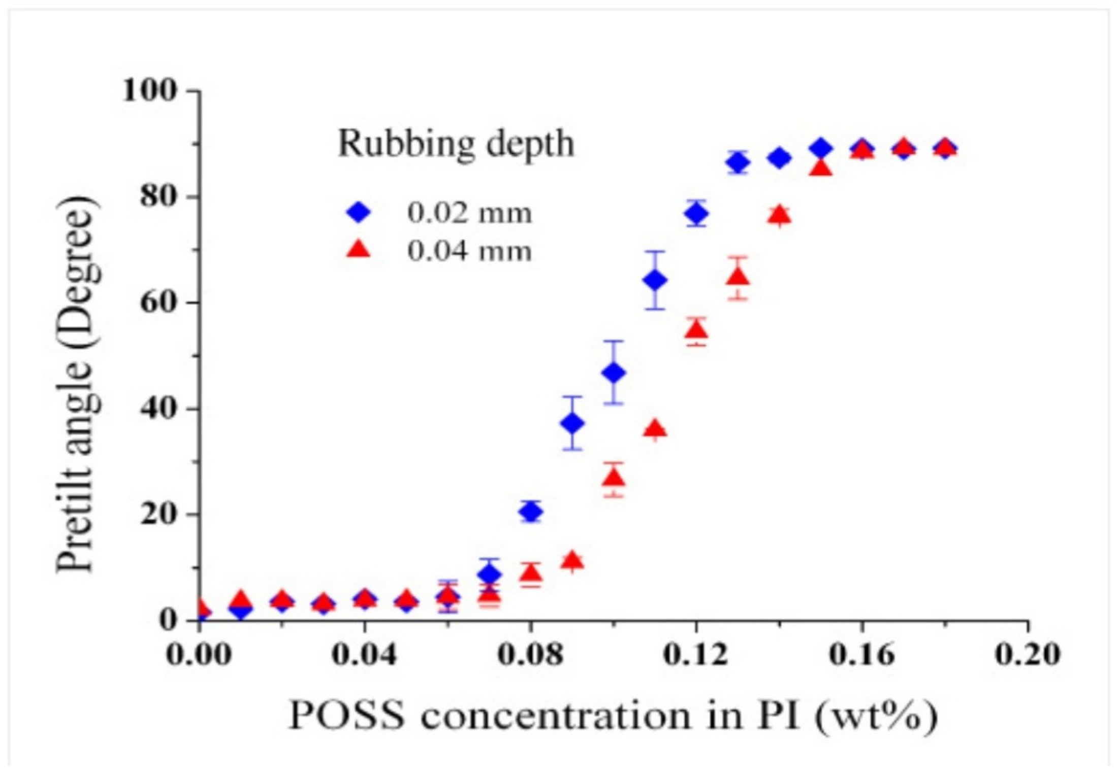
The NPs-induced alignment technique serves an important advantage in the form of achieving variable pretilt angles based on incorporating different concentrations of NPs in the homogeneously aligned LC layer [135]. Hwang et al. observed that the pretilt angular values were found to increase with the increase in the concentration of the doped NPs. Figure 6 demonstrates the variation in the pretilt angles of LC molecules by changing the concentration of POSS NPs in the homogeneously aligned PI material. Precisely, it is the competition between the horizontal alignment due to the rubbed PI layer and the vertical alignment induced by the doped NPs that realigns the LC molecules along the desired pretilt angle. From Figure 6, it can also be inferred that a stronger rubbing depth results in lower pretilt angular values. This is due to the fact that an enhancement of the rubbing depth causes an increase in the polarity of the PI alignment surface. This results in an increase in the forces of attraction between LC molecules and molecules of the alignment layer, thereby leading to a lower pretilt angle. Due to its ability to achieve large pretilt angular values, this alignment technique is beneficial for fabricating no-bias optically compensated bend LC displays, bistable bend-splay displays and bistable super- twisted NLC displays [135,145]. Moreover, the addition of NPs into LCs causes a lowering of the surface energy of the alignment layer as well. The surface tension of the alignment layer has been found to decrease with the increase in the concentration of NPs in the PI layer [135]. Apart from the wide range of pretilt angular values, this technique offers another important advantage [142]. The homeotropic alignment induced in these cells can be electrically reoriented at a much lower Freedericksz transition threshold voltage as compared to pure nematics. Meanwhile, the increase in the pretilt angular values of LC molecules is found to be synonymous to lowering the threshold voltage of the system. This can be attributed to the fact that LC molecules with a high pretilt angle realign easily towards the electric field, thereby reducing the threshold voltage of the system [145].
NPs-based alignment in LCs has undergone important changes in recent years in order to make it more reliable, less temperature-sensitive and more cost-effective [146]. The coating of a photoresponsive material on a particular NP and then doping it into LCs can also help in achieving dual alignment. The resultant system in this case does not require an external field but instead relies on different beam irradiations for a reversible alignment switching mechanism. To corroborate the above statement, the reversible orientational control of the NLC 4 cyano-4ʹ-pentylbiphenyl (which is commonly known as 5CB) was achieved with the help of photoresponsive azobenzene thiol-grafted gold NPs upon UV and visible beam irradiations. The purpose of grafting an azobenzene thiol on gold NPs was twofold. The azobenzene derivatives are usually endowed with the property of photoinduced geometric isomerization. This property enables the azobenzene thiol substance to modulate the functionalized gold NPs and helps in exhibiting different alignments upon beam irradiation. Additionally, there were issues associated with the homogeneous dispersion of gold NPs into the LCs. However, the coating of the azobenzene thiol on these NPs helps in overcoming the dispersion-related problems. It helps in the uniform dispersion of the gold NPs in 5CB even at room temperature. Furthermore, the variations in the wavelength of the irradiated UV and visible beams can also help in switching to the desired LC alignment. Overall, this technique offers numerous advantages over the conventional dual alignment technique as it neither requires any low-frequency electric or magnetic fields for its operation nor any special surface treatment of the aligning substrate.
4. Development Status
The relevance of the alignment of NPs into LCs has been effectively capitalized by various research groups, leading to the fabrication of new materials with exciting electro-optical behavior [133,134,135,136,137,147,148,149,150,151,152,153,154,155,156,157]. These research groups have doped different concentrations of NPs in several LCs in order to observe the alignment effects of the newly formed aggregates on the response time and viewing characteristics of displays along with their contrast ratio [83]. These developments have enabled manufacturers in the LC display industry to produce flexible plastic displays requiring a low-temperature process without using conventional alignment layers.
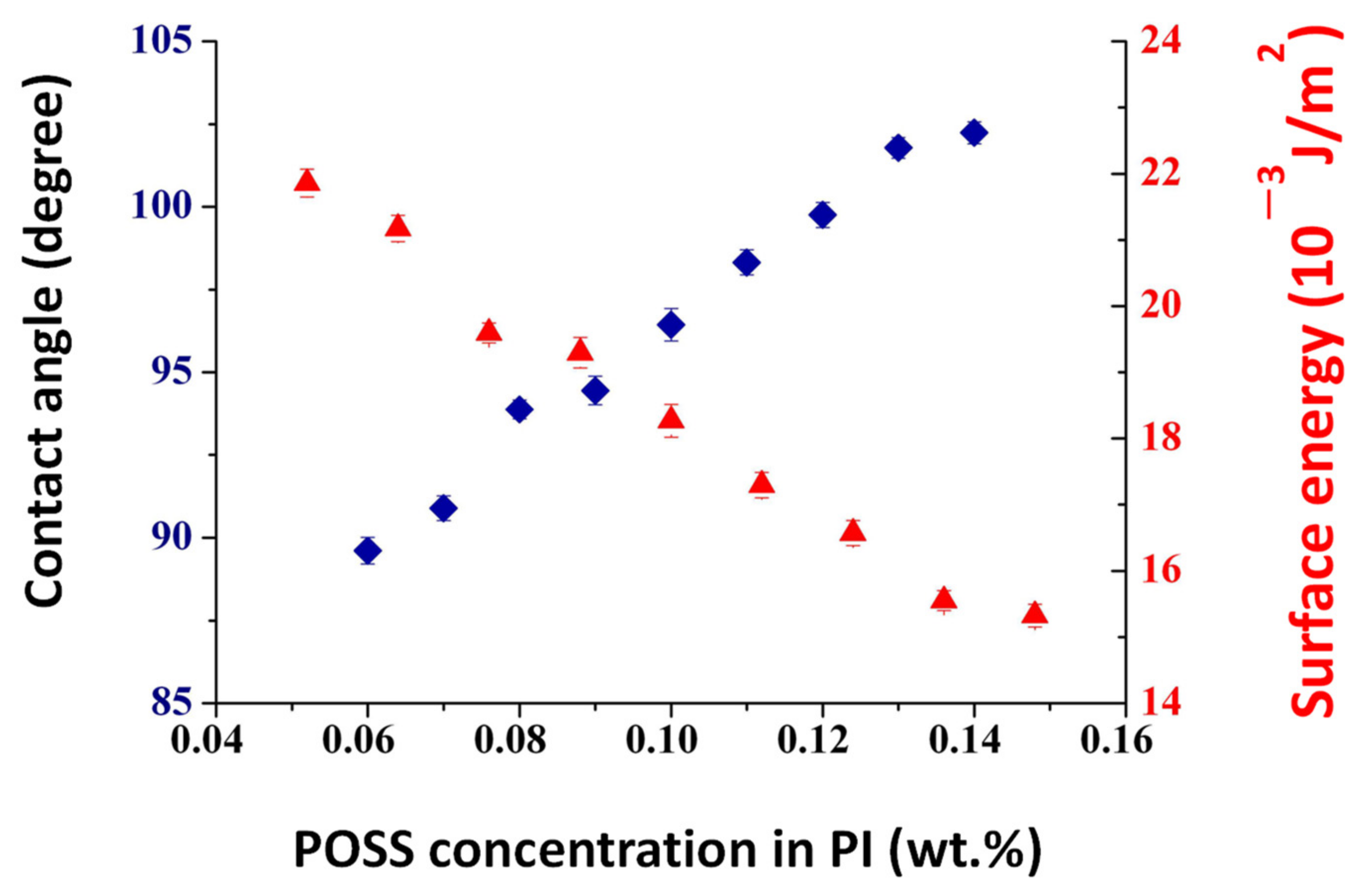
The doping of NPs can also serve as a tool to achieve a wide range of pretilt angles required for the desired LC alignment. Hwang et al. incorporated different concentrations of POSS NPs in the unaligned NLC E7 and observed spontaneous vertical alignment induced in it [135]. An interesting observation incurred by this research group was that the entire range of pretilt angular values (from 0° to 90°) can be generated by varying the concentration of doped POSS NPs from 0 to 0.18 wt.%. Figure 7 explains the variation in the contact angle as well as the surface energy of the POSS-filled E7 mixture as a function of the different concentrations of POSS NPs in it. From Figure 7, it can be observed that the increase in the percentage of NPs in the NLC is found to be synonymous with a decrease in the surface energy of the alignment layers, thereby leading to greater pretilt angle values of the LC cells. Furthermore, it was also observed that when the concentration of these POSS NPs was insufficient, an incomplete vertical alignment of the LC molecules took place [137]. Conversely, when the concentration of these dopants exceeded the threshold limit, these NPs aggregated and caused the light to scatter severely. This degraded the overall electro-optical behavior of the LC-NP composites.
Vimal et al. studied the effect of doping silver NPs in a ferroelectric LC (FLC) mixture, W343, on the alignment and relaxation behavior of the FLC mixture [147]. The study of the polarizing optical micrographic images of the composites gave an insight into the change in alignment of the FLC due to the presence of silver NPs. The alignment of the molecules in the smectic C* phase was found to improve due to the self-aligning nature of the NPs in these FLCs. The interaction between NPs and LC molecules created strong anchoring conditions and therefore resulted in the alignment of these NPs parallel to the rubbed surface. Meanwhile, the effect of doping silver NPs into the concerned FLC mixture was also pronounced in the form of a slight increase in the SmC*–SmA phase transition temperature. Similarly, Kumar et al. doped polymeric (a copolymer of pentacene and benzene) NPs in FLC mixtures and observed spontaneous vertical alignment induced in them [148]. The vertical alignment in these FLC mixtures was confirmed with the help of dielectric relaxation spectroscopy. In this molecular arrangement, the long molecular axis of the LC molecules lies perpendicular to the substrate which prevents the Goldstone mode from taking place. Thus, the only possibility for the molecule available is to rotate about its short molecular axis. This is reflected in the smaller values of the real part of the complex dielectric permittivity. The researchers also studied the influence of doping polymer NPs in FLC mixtures on various parameters such as the transition temperature, threshold voltage and response time of the composites. The response time and threshold voltage were found to decrease in the NP-FLC composites. Furthermore, Kuang et al. studied the alignment control of the NLC 5CB by doping gold NPs fabricated with the help of the two-phase Brust–Schiffrin method [157]. The gold NPs were highly grafted by the liquid crystalline polymer and had azobenzene mesogens as a side chain. A well-dispersed mixture of these gold NPs into the required NLC resulted in a perfect homeotropic alignment. It was concluded that the pure side chain liquid crystalline polymer did not cause vertical alignment in 5CB. This affirmed the fact that the alignment control was due to a synergistic interaction between the gold core and polymers.
The research on the alignment of LCs doped with various NPs has gained intensive pace in the past decade [141]. Zhao et al. doped two different types of nickel NPs: nickel nanospheres (NiNSs) and nickel nanobowls (NiNBs), in nematic as well as cholesteric LCs. The NLCs used were 4 cyano-4ʹ-pentylbiphenyl (which is commonly known as 5CB) and Slichem Liquid Crystal Material (SLC-1717). The CLC mixture was prepared by mixing a chiral dopant, CB15, in SLC-1717 with a weight ratio of 3.0%.
Figure 8 depicts the polarizing optical micrographs of 5CB and the CLC mixture filled in an unaligned LC cell under 0.01 wt.% concentrations of two NPs: NiNSs and NiNBs [141]. For the sample cell only filled with 5CB, a bright state was observed under the crossed polarizers due to the random orientation of the LC molecules, as shown in Figure 8a. From Figure 8b–f, it can be concluded that the alignment mode completely depended on the morphologies of the two different NPs. While the incorporation of nanospheres induced homeotropic alignment in both types of LCs, the doping of nanobowls into them resulted in homogeneous or parallel alignment. However, this alignment effect was pronounced in both types of materials only when the concentrations of the doped NPs were more than 0.01 wt.%. These observations highlight that, apart from the concentration, the physical attributes of the doped NPs also control the alignment mechanism in the host materials as well.
Controlling the molecular alignment in LCs over a macroscopic region is a challenging task. Apart from the alignment control, the doping of NPs into LCs offers the possibility of dual alignment behavior in the presence of the electric field as well. For example, the incorporation of metal or semiconductor NPs such as gold into NLCs has culminated into certain interesting observations [149]. The textural observations of 8CB–gold composites comprises of uniform birefringent stripes which are separated by areas of homeotropic alignment. It is found that composites of gold NPs and 8CB exhibit a chiral nature even though the LC material is achiral. The literature survey has affirmed that the intrinsic chirality induced in the gold NPs is due to the packing of gold atoms in them in a particular manner. Circular dichroism spectropolarimetry experiments performed on the composites have confirmed that the optically active gold NPs have transferred the chirality to the achiral 8CB material. Apart from the chiral nature, the composite also exhibited dual alignment behavior in the presence of the electric field. The 8CB–gold mixture was first heated above its nematic–isotropic transition temperature and then cooled back to its nematic phase under the influence of the electric field. This resulted in the formation of a planar alignment which is also stable even after the removal of the external perturbation. Moreover, these doped NLCs can again be homeotropically aligned by switching from the planar alignment on the application of the electric field with a value above the Freedericksz transition limit. Thus, dual alignment and electro-optical switching can be achieved in these planar-aligned LC cells by doping suitable NPs in them.
Qi and his research team tried to forge alignment in NLCs using gold NPs as a substituent [136]. A critical study of their research work provides a valuable insight into numerous ways in which the alignment of these mesophases can be tuned, reversed or even manipulated with. They highlighted that, apart from the NP concentration or size, even the length of the carbon chain of the alkyl thiolate coated on these nanoscaled substituents plays a vital role in LC alignment as well. To affirm their observations, they synthesized several combinations of NLCs and alkyl thiolate-coated gold NPs suspensions and observed them under crossed polarizers. They observed that as the temperature decreased, the LC textures shifted from being homogeneously aligned to a vertically aligned. This thermal alignment switch phenomenon was attributed to the change in the solubility of these NPs in the host material. At higher temperatures, these NPs were uniformly distributed across the LC matrix, and only those LC molecules which were in contact with the glass substrate controlled the overall alignment. However, at lower temperatures, the order parameter of the NLC improved, and this resulted in expelling some of the embedded NPs to the glass–LC interface. Thus, at the reduced temperatures, NPs control the alignment mechanism of the NLC molecules. Hence, the alignment of NPs-doped NLCs strongly depends on the order parameter of the system, the concentration and solubility of the incorporated NPs and also on the sample preparation conditions.
5. Applications of Nanoparticles-Induced Alignment
The NPs-induced vertical alignment technique in LCs has complemented the efforts of the leading manufacturers of the world in fabricating flexible displays with the desired characteristics without even using the vertical alignment layers [117,135,158]. This simple and economical technique can be used to fabricate an LC microlens device by dropping POSS NPs on a localized area on a homogeneously aligned layer [158]. Since the sprinkling of NPs takes place only on a specific area of the glass substrate, the reorientation of the LC molecules is also distributed spatially, thereby depicting a circularly dispersed pattern. This leads to the development of a concentric non-uniform distribution of the refractive index across the substrate surface, which indirectly serves the purpose of a tunable lens.
In earlier times, many efforts were made by various manufacturers to develop this portable device [117,158]. However, the high driving voltage (of approximately 90 Vrms) and small aperture (of less than 2 mm) have proved to be big deterrents. Thus, researchers swayed their attention to this NPs-induced vertical alignment technique in trying to fabricate an electrically controlled tunable-focal-length lens. The biggest benefit of such a lens is that it is light, compact and also endowed with a low power consumption output [158].
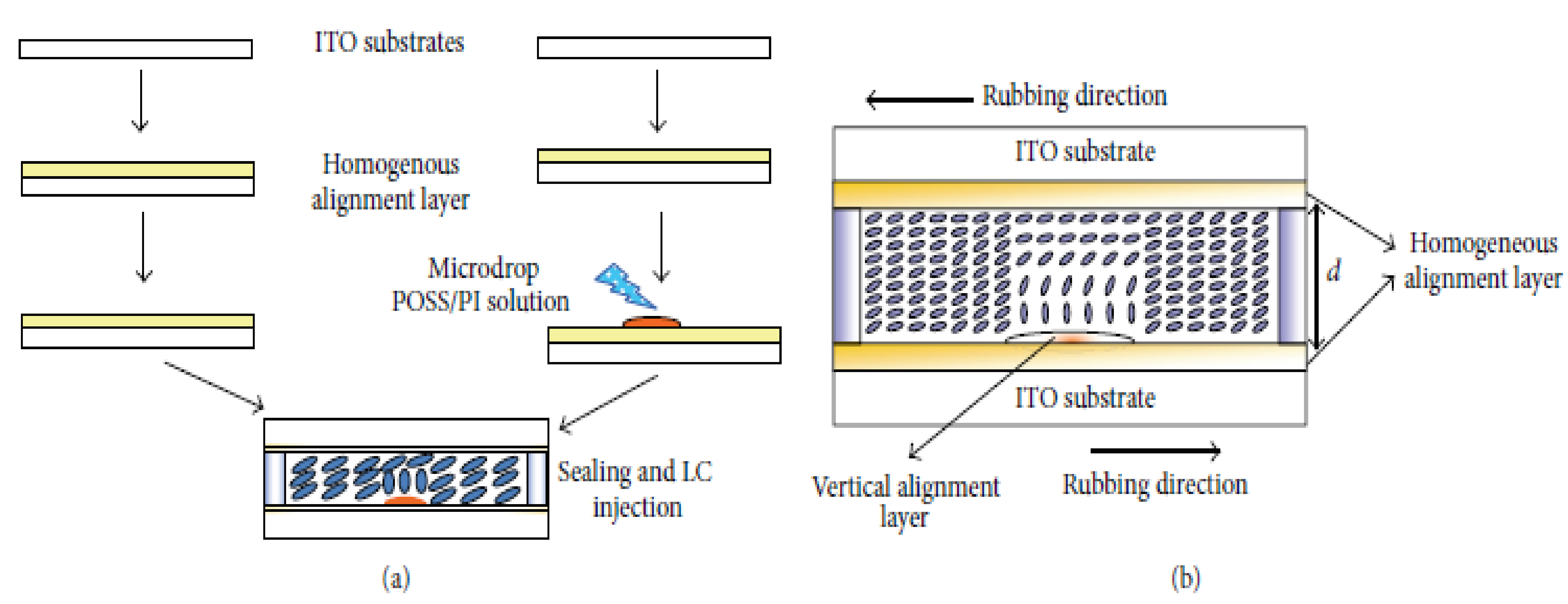
Figure 9a presents the step-by-step procedure involved in the fabrication of an LC microlens by microdropping POSS NPs on a homogeneously aligned substrate [158]. As evident from Figure 9b, only those LC molecules which are in contact with the microdroplets of the POSS NPs are vertically aligned, thus leading to the creation of a hybrid-aligned LC cell.
The overall refractive index related to the extraordinary ray in an LC cell is given by the following equation:
where and are the ordinary and extraordinary refractive indices of the LC material, and is the tilt angle of the LC molecules. Meanwhile, it is observed that the ordinary refractive index does not play a crucial role in controlling the focusing effect of this microlens. Therefore, the extraordinary refractive index only decides the optical properties of this hybrid-aligned LC microlens.
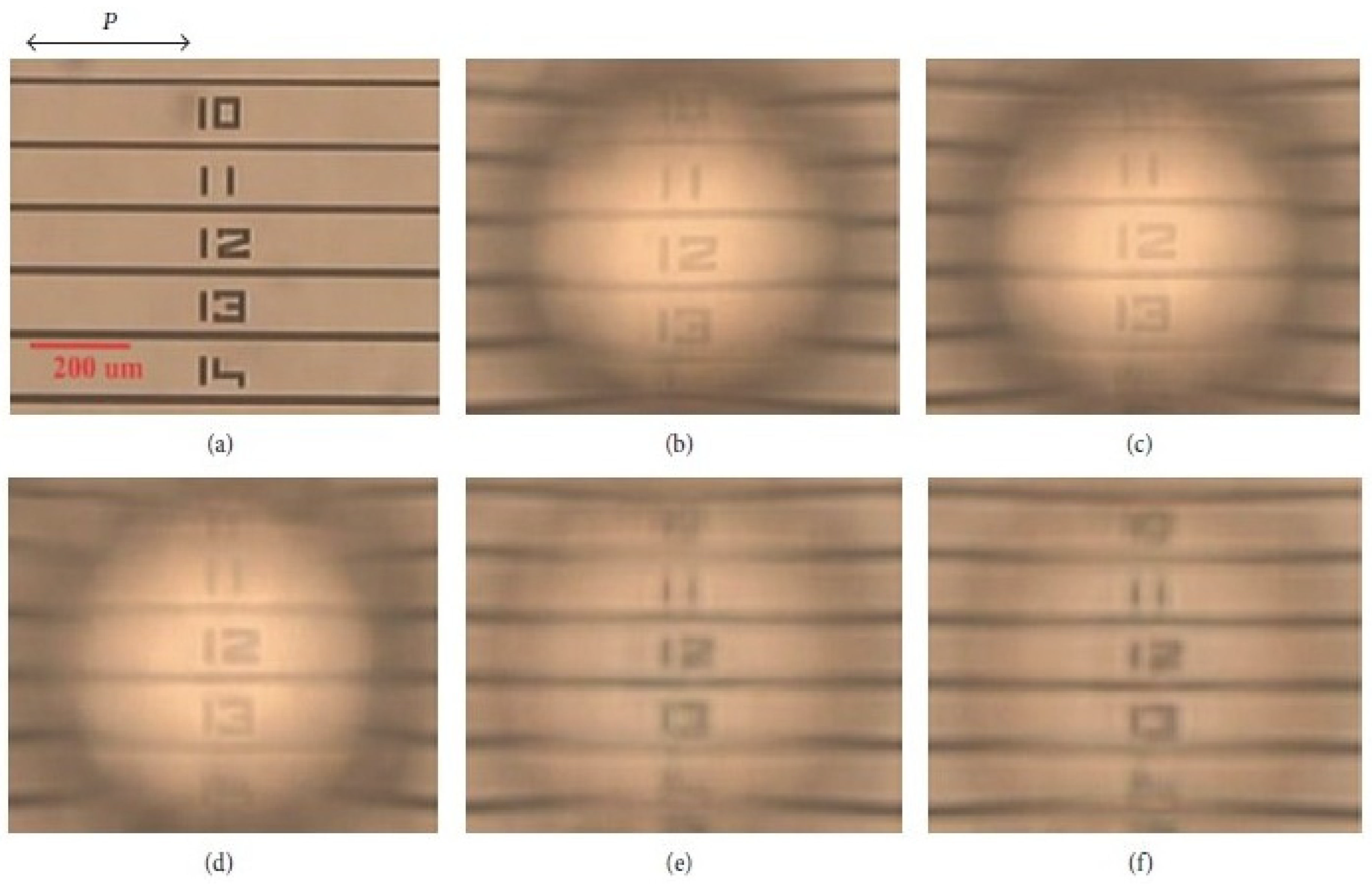
To analyze the voltage-dependent behavior of this LC microlens, it was placed near a card bearing several digits on it. This card served the purpose of an object and was placed at a distance of 10.54 mm from the lens.
Figure 10 depicts the image formation of an object by a hybrid-aligned LC microlens when the applied voltage is increased beyond the threshold voltage (which is approximately equal to 0.5 Vrms). As seen in Figure 10, the image of the object became blurred when the magnitude of the applied voltage was increased. This can be attributed to the fact that when the applied voltage exceeds the Freedericksz transition value, the reorientation of the LC molecules takes place [135,158]. Therefore, the refractive index distribution of the LC microlens is altered and the microlens now serves as a divergent lens. This suggests that in order to focus the image of a nearby object, the magnitude of the applied voltage must be kept below the Freedericksz transition value so as to enable the microlens to behave as a convergent lens.
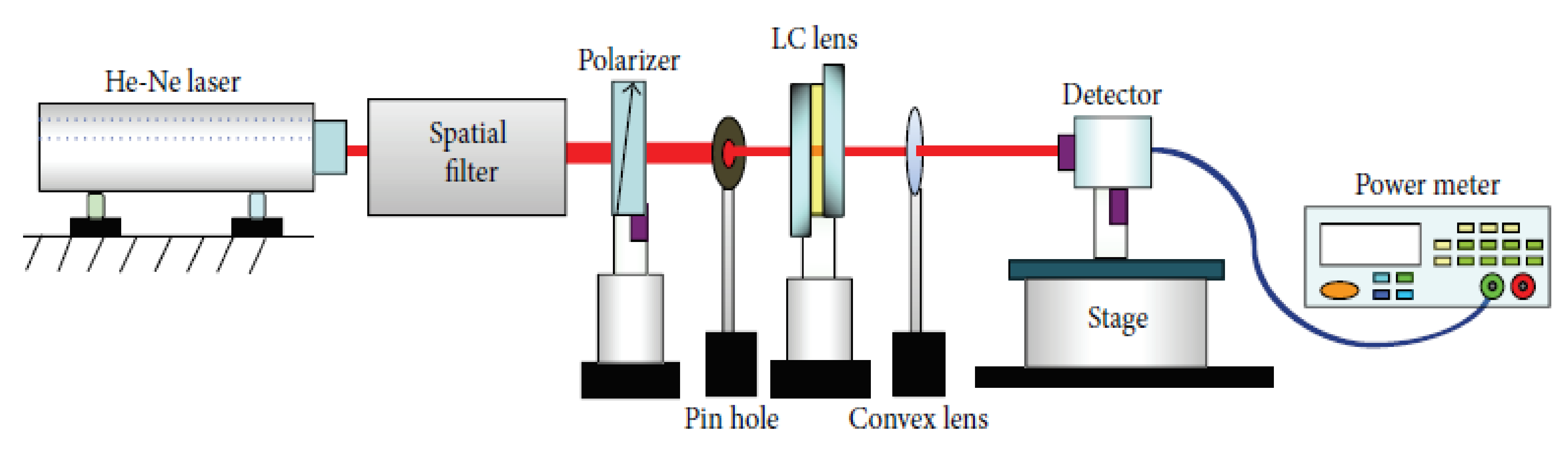
Figure 11 presents a description of an experimental setup to study the variation in interference fringes as a function of the applied voltage for an LC microlens [158]. In this setup, the microlens is placed between two crossed polarizers such that their transmission axes are at 45° with respect to the rubbing direction. A He-Ne laser beam having a wavelength of 0.633 µm was incident on one of the polarizers, and the transformation in interference fringes were observed upon the increment in the applied voltage.
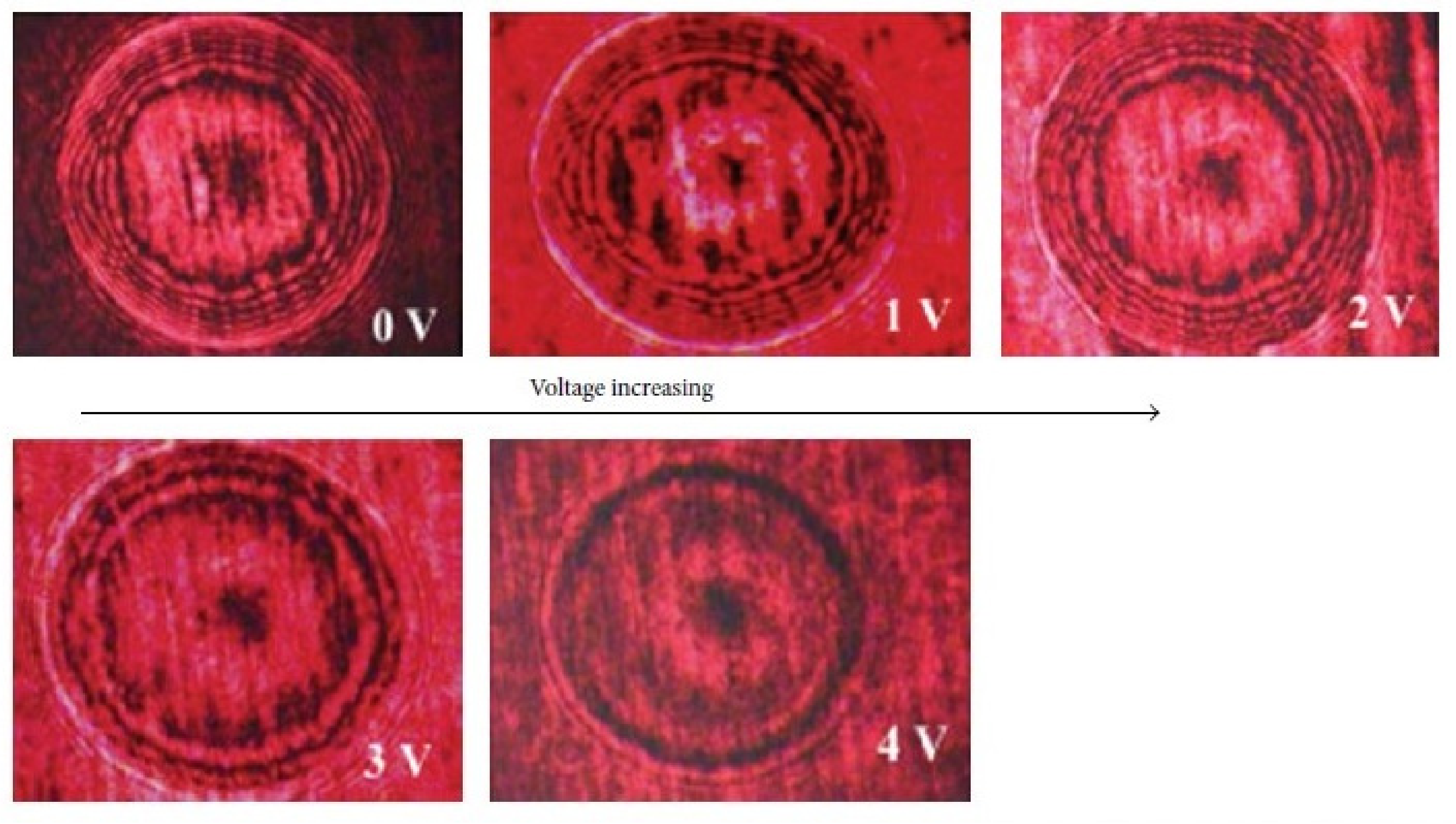
Figure 12 presents the interference patterns of the microlens at different voltages. A close look at these images highlights that the interference pattern is composed of nearly circular fringes. As observed in Figure 12, these circular fringes are found to move from the center to the edge upon increasing the applied voltage. This happens due to the reorientation of the directors of the LC molecules by variations in the applied electric field. As the applied voltage exceeds the Freedericksz threshold transition value, reorientation of the LC directors takes place, and the refractive index distribution is altered. Meanwhile, the focal length of this LC microlens can be calculated from the following equation:
where is the radius of the aperture of the patterned lens, is the wavelength of the incident light, is the total number of fringes and is the focal length of the LC microlens.
Thus, NPs-induced vertical alignment technique offers a unique way to fabricate a cost-effective hybrid-aligned LC microlens which has a low operating voltage and a tunable focal length [117]. By controlling the droplet volume of POSS NPs on homogeneously aligned glass substrates, the LC microlens with a desirable focal length range can be obtained. Due to its simple and cost-effective fabrication procedure, this LC microlens may find numerous applications in various optical devices such as 3D displays, imaging systems and optical tweezers.
6. Conclusions and Outlook
Research in LCs has made rapid strides with their innovative and diverse applications in the field of nanoscience and nanotechnology. The present review highlights the relevance of the alignment control of LC molecules in various applications in order to achieve the desired electro-optical behavior. The different ways to align LC molecules have been systematically explained, and the advantageous nature of NPs-induced alignment technique has been stressed upon. Apart from being cost-effective and reliable, this NPs-induced alignment technique offers the advantage of achieving a wide range of pretilt angles which are useful for mature display industries. Furthermore, this alignment method does not require extreme physical conditions such as a high vacuum and is useful for fabricating flexible plastic displays as well. The detailed development status of this technique gives an insight into numerous ways in which it was capitalized by various research groups to obtain the desired alignment properties. Several research works have corroborated the fact that the alignment behavior of NPs-doped LCs strongly depends on the shape, size, solubility as well as concentration of the former in the latter. Apart from these, the sample preparation conditions and order parameter of the system also play a vital role in tailoring the alignment behavior in these composites. These recent developments have led to the fabrication of a hybrid-aligned LC microlens by selective microdropping of NPs on a localized area of a homogeneously aligned layer. The focal length of these lenses can be electrically tuned by the applied electric fields due to the reorientation of the directors of LC molecules. Considerable challenges still exist related to the efficiency and stability of this hybrid-aligned microlens. The development of a wide spectrum of nanomaterials in the coming years will be helpful in improving this technique to a large extent. The quest for more cost-effective materials with refined dielectric and electro-optical characteristics will direct researchers to further refine this alignment technique in order to use it in various biomedical applications.
Author Contributions
Conceptualization, J.P. and S.C.; methodology, J.P.; resources, A.K.; writing—original draft preparation, A.K.; writing—review and editing, J.P. and S.C.; visualization, J.P.; supervision, J.P. and S.C.; funding acquisition, J.P. All authors have read and agreed to the published version of the manuscript.
Funding
The author Akash Kumar would also like to thank the University Grants Commission (UGC), India, for providing the Junior Research Fellowship for the sake of financial support. One of the authors, Jai Prakash, is grateful to the Department of Science and Technology (DST) and the Council of Scientific and Industrial Research (CSIR), New Delhi, India, for supporting this work under the Science and Engineering Research Board (SERB)-funded EMR project (EMR/2016/006142) and EMR project (No. 03 (1395)/17/EMR-II), respectively.
Data Availability Statement
Not applicable.
Conflicts of Interest
The authors declare no conflict of interest.
References
- Prakash, J.; Chandran, A.; Biradar, A.M. Scientific developments of liquid crystal-based optical memory: A review. Rep. Prog. Phys. 2016, 80, 016601. [Google Scholar] [CrossRef] [PubMed]
- Singh, S.; Dunmur, P.D.A. Liquid Crystals; World Scientific Publishing Co. Pte. Ltd.: Singapore, 2002; pp. 1–531. [Google Scholar] [CrossRef]
- Lagerwall, J.P.F.; Scalia, G. A new era for liquid crystal research: Applications of liquid crystals in soft matter nano-, bio- and microtechnology. Curr. Appl. Phys. 2012, 12, 1387–1412. [Google Scholar] [CrossRef]
- Prakash, J.; Khan, S.; Chauhan, S.; Biradar, A. Metal oxide-nanoparticles and liquid crystal composites: A review of recent progress. J. Mol. Liq. 2020, 297, 112052. [Google Scholar] [CrossRef]
- Andrienko, D. Introduction to liquid crystals. J. Mol. Liq. 2018, 267, 520–541. [Google Scholar] [CrossRef]
- Kamei, T.; Utsumi, Y.; Moritake, H.; Toda, K.; Suzuki, H. Measurements of the dielectric properties of nematic liquid crystals at 10 kHz to 40 GHz and application to a variable delay line. Electron. Commun. Jpn. 2003, 86, 49–60. [Google Scholar] [CrossRef]
- Naemura, S. Liquid-crystal-material technologies for advanced display applications. J. Soc. Inf. Disp. 2000, 8, 5–9. [Google Scholar] [CrossRef]
- Miniewicz, A.; Gniewek, A.; Parka, J. Liquid crystals for photonic applications. Opt. Mater. 2002, 21, 605–610. [Google Scholar] [CrossRef]
- Wang, L.; Urbas, A.M.; Li, Q. Nature-Inspired Emerging Chiral Liquid Crystal Nanostructures: From Molecular Self-Assembly to DNA Mesophase and Nanocolloids. Adv. Mater. 2018, 32, e1801335. [Google Scholar] [CrossRef]
- Brach, K.; Hatakeyama, A.; Nogues, C.; Olesiak-Banska, J.; Buckle, M.; Matczyszyn, K. Photochemical analysis of structural transitions in DNA liquid crystals reveals differences in spatial structure of DNA molecules organized in liquid crystalline form. Sci. Rep. 2018, 8, 4528. [Google Scholar] [CrossRef]
- Kowerdziej, R.; Parka, J.; Krupka, J.; Olifierczuk, M.; Nowinowski-Kruszelnicki, E.; Jaroszewicz, L.; Chojnowska, O. Dielectric properties of highly anisotropic nematic liquid crystals for tunable microwave components. Appl. Phys. Lett. 2013, 103, 172902. [Google Scholar] [CrossRef]
- Canli, N.Y.; Özdemir, Z.G.; Okutan, M.; Güzeller, D.; Ocak, H.; Eran, B.B. Dielectric Properties of 4-Cyano-4′-pentylbiphenyl (5CB): 4-[4-(S)-2-Methylbutoxybenzoyloxy]benzoic Acid (BAC) Composite. Mol. Cryst. Liq. Cryst. 2015, 623, 17–30. [Google Scholar] [CrossRef]
- Kumar, A.; Varshney, D.; Prakash, J. Role of ionic contribution in dielectric behaviour of a nematic liquid crystal with variable cell thickness. J. Mol. Liq. 2020, 303, 112520. [Google Scholar] [CrossRef]
- Popov, N.; Honaker, L.W.; Popova, M.; Usol’Tseva, N.; Mann, E.K.; Jákli, A.; Popov, P. Thermotropic Liquid Crystal-Assisted Chemical and Biological Sensors. Materials 2017, 11, 20. [Google Scholar] [CrossRef] [PubMed] [Green Version]
- Darla, M.R.; Varghese, S. Synthesis and characterisation of azomethine class thermotropic liquid crystals and their application in nonlinear optics. Liq. Cryst. 2012, 39, 63–70. [Google Scholar] [CrossRef]
- Kovshev, E.I.; Blinov, L.M.; Titov, V.V. Thermotropic Liquid Crystals and Their Applications. Russ. Chem. Rev. 1977, 46, 395–419. [Google Scholar] [CrossRef]
- Bunjes, H.; Rades, T. Thermotropic liquid crystalline drugs. J. Pharm. Pharmacol. 2005, 57, 807–816. [Google Scholar] [CrossRef]
- Guo, C.; Wang, J.; Cao, F.; Lee, R.J.; Zhai, G. Lyotropic liquid crystal systems in drug delivery. Drug Discov. Today 2010, 15, 1032–1040. [Google Scholar] [CrossRef]
- Kim, D.-H.; Jahn, A.; Cho, S.-J.; Kim, J.S.; Ki, M.-H.; Kim, D.-D. Lyotropic liquid crystal systems in drug delivery: A review. J. Pharm. Investig. 2014, 45, 1–11. [Google Scholar] [CrossRef]
- Garti, N.; Libster, D.; Aserin, A. Lipid polymorphism in lyotropic liquid crystals for triggered release of bioactives. Food Funct. 2012, 3, 700–713. [Google Scholar] [CrossRef]
- Forrest, B.J.; Reeves, L.W. New lyotropic liquid crystals composed of finite nonspherical micelles. Chem. Rev. 1981, 81, 1–14. [Google Scholar] [CrossRef]
- Sergeyev, S.; Pisula, W.; Geerts, Y.H. Discotic liquid crystals: A new generation of organic semiconductors. Chem. Soc. Rev. 2007, 36, 1902–1929. [Google Scholar] [CrossRef] [PubMed]
- Boden, N.; Bushby, R.J.; Clements, J.; Movaghar, B.; Donovan, K.J.; Kreouzis, T. Mechanism of charge transport in discotic liquid crystals. Phys. Rev. B 1995, 52, 13274–13280. [Google Scholar] [CrossRef] [PubMed]
- Bushby, R.J.; Kawata, K. Liquid crystals that affected the world: Discotic liquid crystals. Liq. Cryst. 2011, 38, 1415–1426. [Google Scholar] [CrossRef]
- Ros, M.B.; Serrano, J.L.; de la Fuente, M.R.; Folcia, C.L. Banana-shaped liquid crystals: A new field to explore. J. Mater. Chem. 2005, 15, 5093–5098. [Google Scholar] [CrossRef]
- De Almeida, R.R.; Zhang, C.; Parri, O.; Sprunt, S.; Jakli, A. Nanostructure and dielectric properties of a twist-bend nematic liquid crystal mixture. Liq. Cryst. 2014, 41, 1661–1667. [Google Scholar] [CrossRef]
- Kim, Y.B.; Hur, I.K. High speed response time of nematic liquid crystal mixtures for LCD monitor and TV applications. J. Inf. Disp. 2001, 2, 32–38. [Google Scholar] [CrossRef]
- Yazdanpanahi, M.; Bulja, S.; Mirshekar-Syahkal, D.; James, R.; Day, S.E.; Fernandez, F.A. Measurement of Dielectric Constants of Nematic Liquid Crystals at mm-Wave Frequencies Using Patch Resonator. IEEE Trans. Instrum. Meas. 2010, 59, 3079–3085. [Google Scholar] [CrossRef]
- Varshney, D.; Kumar, A.; Prakash, J.; Meena, R.; Asokan, K. Gamma irradiation induced dielectric modulation and dynamic memory in nematic liquid crystal materials. J. Mol. Liq. 2020, 320, 114374. [Google Scholar] [CrossRef]
- Dierking, I.; Mitov, M.; Osipov, M.A. Smectic layer instabilities in liquid crystals. Soft Matter 2014, 11, 819–837. [Google Scholar] [CrossRef] [Green Version]
- Bohley, C.; Stannarius, R. Inclusions in free standing smectic liquid crystal films. Soft Matter 2008, 4, 683–702. [Google Scholar] [CrossRef]
- Langer, S.A.; Sethna, J.P. Textures in a chiral smectic liquid-crystal film. Phys. Rev. A 1986, 34, 5035–5046. [Google Scholar] [CrossRef] [PubMed]
- Soni, S.; Bishnoi, D.D.; Soni, S. Ramswroop liquid crystals and applications of chlosteric liquid crystal in laser. Int. J. Mod. Phys. Conf. Ser. 2013, 22, 736–740. [Google Scholar] [CrossRef]
- Kim, Y.; Wada, M.; Tamaoki, N. Dicholesteryl icosanedioate as a glass-forming cholesteric liquid crystal: Properties, additive effects and application in color recording. J. Mater. Chem. C 2014, 2, 1921–1926. [Google Scholar] [CrossRef]
- Ryabchun, A.; Bobrovsky, A. Cholesteric Liquid Crystal Materials for Tunable Diffractive Optics. Adv. Opt. Mater. 2018, 6, 1–20. [Google Scholar] [CrossRef]
- Coates, D. Development and applications of cholesteric liquid crystals. Liq. Cryst. 2015, 42, 1–13. [Google Scholar] [CrossRef]
- Salamończyk, M.; Vaupotič, N.; Pociecha, D.; Walker, R.; Storey, J.; Imrie, C.T.; Wang, C.; Zhu, C.; Gorecka, E. Multi-level chirality in liquid crystals formed by achiral molecules. Nat. Commun. 2019, 10, 1922. [Google Scholar] [CrossRef]
- Tournilhac, F.; Blinov, L.M.; Simon, J.; Yablonsky, S.V. Ferroelectric liquid crystals from achiral molecules. Nature 1992, 359, 621–623. [Google Scholar] [CrossRef]
- Skarp, K.; Handschy, M. Ferroelectric Liquid Crystals. Material Properties and Applications. Mol. Cryst. Liq. Cryst. Inc. Nonlinear Opt. 1988, 165, 439–509. [Google Scholar] [CrossRef]
- Lagerwall, J.P.F.; Giesselmann, F. Current Topics in Smectic Liquid Crystal Research. ChemPhysChem 2006, 7, 20–45. [Google Scholar] [CrossRef]
- Das, M.K.; Barman, B.; Das, B.; Hamplová, V.; Bubnov, A. Dielectric Properties of Chiral Ferroelectric Liquid Crystalline Compounds with Three Aromatic Rings Connected by Ester Groups. Crystals 2019, 9, 473. [Google Scholar] [CrossRef] [Green Version]
- Ważyńska, B.; Tykarska, M.; Okowiak-Chinalska, J. New Application of Thermotropic Liquid Crystals. Mol. Cryst. Liq. Cryst. 2011, 542, 213–220. [Google Scholar] [CrossRef]
- Castellano, J.A. Liquid Crystal Display Applications: Past, Present & Future. Liq. Cryst. Today 1991, 1, 4–6. [Google Scholar] [CrossRef] [Green Version]
- Gauza, S.; Wen, C.-H.; Wu, B.; Wu, S.-T.; Spadlo, A.; Dąbrowski, R. Fast-response nematic liquid-crystal mixtures. J. Soc. Inf. Disp. 2006, 14, 241–246. [Google Scholar] [CrossRef]
- Tomilin, M.G.; Povzun, S.A.; Kurmashev, A.F.; Gribanova, E.V.; Efimova, T.A. The application of nematic liquid crystals for objective microscopic diagnosis of cancer. Liq. Cryst. Today 2001, 10, 3–5. [Google Scholar] [CrossRef] [Green Version]
- Chilaya, G.; Chanishvili, A.; Petriashvili, G.; Barberi, R.; De Santo, M.P.; Matranga, M.A. Different Approaches of Employing Cholesteric Liquid Crystals in Dye Lasers. Mater. Sci. Appl. 2011, 2, 116–129. [Google Scholar] [CrossRef] [Green Version]
- Manabe, T.; Sonoyama, K.; Takanishi, Y.; Ishikawa, K.; Takezoe, H. Toward practical application of cholesteric liquid crystals to tunable lasers. J. Mater. Chem. 2008, 18, 3040–3043. [Google Scholar] [CrossRef]
- Uchimura, M.; Watanabe, Y.; Araoka, F.; Watanabe, J.; Takezoe, H.; Konishi, G.-I. Development of Laser Dyes to Realize Low Threshold in Dye-Doped Cholesteric Liquid Crystal Lasers. Adv. Mater. 2010, 22, 4473–4478. [Google Scholar] [CrossRef]
- Negrini, R.; Mezzenga, R. pH-Responsive Lyotropic Liquid Crystals for Controlled Drug Delivery. Langmuir 2011, 27, 5296–5303. [Google Scholar] [CrossRef]
- Dierking, I.; Neto, A.M.F. Novel Trends in Lyotropic Liquid Crystals. Crystals 2020, 10, 604. [Google Scholar] [CrossRef]
- Chen, Y.; Ma, P.; Gui, S. Cubic and Hexagonal Liquid Crystals as Drug Delivery Systems. BioMed Res. Int. 2014, 2014, 815981. [Google Scholar] [CrossRef]
- Sonin, A.S.; Churochkina, N.A.; Kaznacheev, A.V.; Golovanov, A.V. Liquid Crystals of Clay Dispersions. Colloid J. 2018, 80, 593–614. [Google Scholar] [CrossRef]
- Kumar, H.; Sureshkumar, A.; Badduri, N.; Jain, V. A Review on Lyotropic Liquid Crystals and Its Potential Applications. Nanosci. Nanotechnol. Asia 2021, 11, 1–14. [Google Scholar] [CrossRef]
- Marzal, V.; Caño, M.; Torres, J.C.; Quintana, X.; Pérez, I.; Garcia-Camara, B. Electrical Behavior of Liquid Crystal Devices with Dielectric Nanoparticles. J. Nanomater. 2020, 2020, 4515432. [Google Scholar] [CrossRef]
- Mirzaei, J.; Reznikov, M.; Hegmann, T. Quantum dots as liquid crystal dopants. J. Mater. Chem. 2012, 22, 22350–22365. [Google Scholar] [CrossRef] [Green Version]
- Bisoyi, H.K.; Kumar, S. Liquid-crystal nanoscience: An emerging avenue of soft self-assembly. Chem. Soc. Rev. 2010, 40, 306–319. [Google Scholar] [CrossRef]
- Hegmann, T.; Qi, H.; Marx, V.M. Nanoparticles in liquid crystals:synthesis, self-assembly, defect formation and potential applications. J. Inorg. Organomet. Polym. 2007, 17, 483–508. [Google Scholar] [CrossRef]
- Shen, Y.; Dierking, I. Perspectives in Liquid-Crystal-Aided Nanotechnology and Nanoscience. Appl. Sci. 2019, 9, 2512. [Google Scholar] [CrossRef] [Green Version]
- Scolari, L.; Gauza, S.; Xianyu, H.; Zhai, L.; Eskildsen, L.; Alkeskjold, T.T.; Wu, S.-T.; Bjarklev, A. Frequency tunability of solid-core photonic crystal fibers filled with nanoparticle-doped liquid crystals. Opt. Express 2009, 17, 3754–3764. [Google Scholar] [CrossRef] [Green Version]
- Gdovinová, V.; Tomašovičová, N.; Jeng, S.-C.; Zakutanská, K.; Kula, P.; Kopčanský, P. Memory effect in nematic phase of liquid crystal doped with magnetic and non-magnetic nanoparticles. J. Mol. Liq. 2019, 282, 286–291. [Google Scholar] [CrossRef]
- Budaszewski, D.; Siarkowska, A.; Chychłowski, M.; Jankiewicz, B.; Bartosewicz, B.; Dąbrowski, R.; Woliński, T.R. Nanoparticles-enhanced photonic liquid crystal fibers. J. Mol. Liq. 2018, 267, 271–278. [Google Scholar] [CrossRef]
- Siarkowska, A.; Chychłowski, M.; Budaszewski, D.; Jankiewicz, B.; Bartosewicz, B.; Wolinski, T.R. Thermo- and electro-optical properties of photonic liquid crystal fibers doped with gold nanoparticles. Beilstein J. Nanotechnol. 2017, 8, 2790–2801. [Google Scholar] [CrossRef] [PubMed] [Green Version]
- Rodarte, A.L.; Nuno, Z.S.; Cao, B.H.; Pandolfi, R.J.; Quint, M.T.; Ghosh, S.; Hein, J.E.; Hirst, L.S. Tuning Quantum-Dot Organization in Liquid Crystals for Robust Photonic Applications. ChemPhysChem 2014, 15, 1413–1421. [Google Scholar] [CrossRef] [PubMed] [Green Version]
- Kumar, S.; Sagar, L.K. CdSe quantum dots in a columnar matrix. Chem. Commun. 2011, 47, 12182–12184. [Google Scholar] [CrossRef] [PubMed]
- Kumar, J.; Gupta, R.K.; Kumar, S.; Manjuladevi, V. Electro-Optic and Dielectric Studies on Quantum Dot Doped Nematic Liquid Crystal. Macromol. Symp. 2015, 357, 47–51. [Google Scholar] [CrossRef]
- Kurochkina, M.A.; Shcherbinin, D.P.; Konshina, E.A. Control of photoluminescence of CdSe/ZnS quantum dots in a nematic liquid crystal by an electric field. Opt. Spectrosc. 2015, 119, 812–815. [Google Scholar] [CrossRef]
- Yaroshchuk, O.; Kravchuk, R.; Dobrovolskyy, A.; Qiu, L.; Lavrentovich, O.D. Planar and tilted uniform alignment of liquid crystals by plasma-treated substrates. Liq. Cryst. 2004, 31, 859–869. [Google Scholar] [CrossRef]
- Nobles, J.E.; Melnyk, O.; Glushchenko, A.; Camley, R.E.; Celinski, Z. Effect of alignment methods on liquid crystal performance in millimeter wave devices. Eng. Res. Express 2020, 2, 025002. [Google Scholar] [CrossRef]
- Ishihara, S.; Mizusaki, M. Alignment control technology of liquid crystal molecules. J. Soc. Inf. Disp. 2019, 28, 44–74. [Google Scholar] [CrossRef]
- Kahn, F.; Taylor, G.; Schonhorn, H. Surface-produced alignment of liquid crystals. Proc. IEEE 1973, 61, 823–828. [Google Scholar] [CrossRef]
- Sato, Y.; Sato, K.; Uchida, T. Relationship between Rubbing Strength and Surface Anchoring of Nematic Liquid Crystal. Jpn. J. Appl. Phys. 1992, 31, L579–L581. [Google Scholar] [CrossRef]
- Yokoyama, H. Surface Anchoring of Nematic Liquid Crystals. Mol. Cryst. Liq. Cryst. Inc. Nonlinear Opt. 1988, 165, 265–316. [Google Scholar] [CrossRef]
- Weng, L.; Liao, P.-C.; Lin, C.-C.; Ting, T.-L.; Hsu, W.-H.; Su, J.-J.; Chien, L.-C. Anchoring energy enhancement and pretilt angle control of liquid crystal alignment on polymerized surfaces. AIP Adv. 2015, 5, 097218. [Google Scholar] [CrossRef] [Green Version]
- Lu, Z.; Deng, H.; Wei, Y. Alignment of liquid crystals on ultrathin organized molecular films. Supramol. Sci. 1998, 5, 649–655. [Google Scholar] [CrossRef]
- Lu, M.; Yang, K.H.; Nakasogi, T.; Chey, S.J. 29.4: Homeotropic Alignment by Single Oblique Evaporation of SiO 2 and Its Application to High Resolution Microdisplays. SID Symp. Dig. Tech. Pap. 2000, 31, 446–449. [Google Scholar] [CrossRef]
- Yamahara, M.; Nakamura, M.; Koide, N.; Sasaki, T. Influence of rubbing conditions of polyimide alignment layer on optical anisotropy of immobilized liquid crystal film. Liq. Cryst. 2007, 34, 381–387. [Google Scholar] [CrossRef]
- Stöhr, J.; Samant, M. Liquid crystal alignment by rubbed polymer surfaces: A microscopic bond orientation model. J. Electron Spectrosc. Relat. Phenom. 1999, 98–99, 189–207. [Google Scholar] [CrossRef]
- Chen, C.; Bos, P.J.; Kim, J.; Li, Q.; Anderson, J.E. Improved liquid crystals for vertical alignment applications. J. Appl. Phys. 2006, 99, 123523. [Google Scholar] [CrossRef]
- Seo, D.; Kobayashi, S. Effect of high pretilt angle for anchoring strength in nematic liquid crystal on rubbed polyimide surface containing trifluoromethyl moieties. Appl. Phys. Lett. 1995, 66, 1202–1204. [Google Scholar] [CrossRef]
- Jeong, E.; Lim, Y.J.; Rhee, J.M.; Lee, S.H.; Lee, G.-D.; Park, K.H.; Choi, H.C. Viewing angle switching of vertical alignment liquid crystal displays by controlling birefringence of homogenously aligned liquid crystal layer. Appl. Phys. Lett. 2007, 90, 051116. [Google Scholar] [CrossRef]
- Hong, H.K.; Yoon, J.K.; Lim, M. Analysis of the dependence of optical response time of liquid crystal displays on the viewing direction. J. Soc. Inf. Disp. 2008, 16, 1063–1068. [Google Scholar] [CrossRef]
- Wu, S.-T. Phase retardation dependent optical response time of parallel-aligned liquid crystals. J. Appl. Phys. 1986, 60, 1836–1838. [Google Scholar] [CrossRef]
- Kundu, S.; Akimoto, M.; Hirayama, I.; Inoue, M.; Kobayashi, S.; Takatoh, K. Enhancement of Contrast Ratio by Using Ferroelectric Nanoparticles in the Alignment Layer of Liquid Crystal Display. Jpn. J. Appl. Phys. 2008, 47, 4751–4754. [Google Scholar] [CrossRef]
- Oh, S.-W.; Park, J.-H.; Yoon, T.-H. Near-zero pretilt alignment of liquid crystals using polyimide films doped with UV-curable polymer. Opt. Express 2015, 23, 1044–1051. [Google Scholar] [CrossRef] [PubMed]
- Choi, Y.; Yokoyama, H.; Gwag, J.S. Determination of surface nematic liquid crystal anchoring strength using nano-scale surface grooves. Opt. Express 2013, 21, 12135–12144. [Google Scholar] [CrossRef] [PubMed]
- Castellano, J.A. Surface Anchoring of Liquid Crystal Molecules on Various Substrates. Mol. Cryst. Liq. Cryst. 1983, 94, 33–41. [Google Scholar] [CrossRef]
- Zhang, B.; Lee, F.K.; Tsui, O.K.C.; Sheng, P. Liquid Crystal Orientation Transition on Microtextured Substrates. Phys. Rev. Lett. 2003, 91, 215501. [Google Scholar] [CrossRef] [Green Version]
- Seo, D.-S. Effect of pretilt angle on the polar anchoring energy in NLCs on weakly rubbed polyimide surfaces. Liq. Cryst. 1999, 26, 1615–1619. [Google Scholar] [CrossRef]
- Yokoyama, H.; van Sprang, H.A. A novel method for determining the anchoring energy function at a nematic liquid crystal-wall interface from director distortions at high fields. J. Appl. Phys. 1985, 57, 4520–4526. [Google Scholar] [CrossRef]
- Wu, W.-Y.; Wang, C.-C.; Fuh, A.Y.-G. Controlling pre-tilt angles of liquid crystal using mixed polyimide alignment layer. Opt. Express 2008, 16, 17131–17137. [Google Scholar] [CrossRef]
- Varghese, S.; Crawford, G.P.; Bastiaansen, C.W.M.; de Boer, D.K.G.; Broer, D.J. Microrubbing technique to produce high pretilt multidomain liquid crystal alignment. Appl. Phys. Lett. 2004, 85, 230–232. [Google Scholar] [CrossRef] [Green Version]
- Jang, A.-R.; Chae, B.; Gil, E.K.; Bae, J.; Lee, S.W. Comparison of Liquid Crystal Alignments on Rubbed and Linearly Polarized UV-Irradiated Polyimide Surfaces. Mol. Cryst. Liq. Cryst. 2012, 563, 10–18. [Google Scholar] [CrossRef]
- Van Aerle, N.A.J.M.; Tol, A.J.W. Molecular Orientation in Rubbed Polyimide Alignment Layers Used for Liquid-Crystal Displays. Macromolecules 1994, 27, 6520–6526. [Google Scholar] [CrossRef]
- Ishihara, S.; Wakemoto, H.; Nakazima, K.; Matsuo, Y. The effect of rubbed polymer films on the liquid crystal alignment. Liq. Cryst. 1989, 4, 669–675. [Google Scholar] [CrossRef]
- Kim, Y.J.; Zhuang, Z.; Patel, J.S. Effect of multidirection rubbing on the alignment of nematic liquid crystal. Appl. Phys. Lett. 2000, 77, 513–515. [Google Scholar] [CrossRef]
- Stôhr, J.; Samant, M.G.; Cossy-Favre, A.; Diaz, J.; Momoi, Y.; Odahara, S.; Nagata, T. Microscopic origin of liquid crystal alignment on rubbed polymer surfaces. Macromolecules 1998, 31, 1942–1946. [Google Scholar] [CrossRef]
- Seo, D.; Kobayashi, S.; Mochizuki, A. Generation of the pretilt angles in nematic liquid crystal (5CB) aligned on the rubbed polypyrrole films. Appl. Phys. Lett. 1992, 60, 1025–1026. [Google Scholar] [CrossRef]
- Hatoh, H.; Yamamoto, T.; Morizumi, Y.; Okamoto, M.; Kubo, A. Dependence of pretilt angle on the topography of substrate in liquid crystal alignment brought about by rubbing technique. Appl. Phys. Lett. 1994, 64, 1103–1104. [Google Scholar] [CrossRef]
- Mosley, A.; Nicholas, B.; Gass, P. Surface alignment of liquid crystals by rubbed polymer layers. Displays 1987, 8, 17–21. [Google Scholar] [CrossRef]
- Janning, J.L. Thin film surface orientation for liquid crystals. Appl. Phys. Lett. 1972, 21, 173–174. [Google Scholar] [CrossRef]
- Johnson, M.; Penz, P. Low-tilt-angle nematic alignment compatible with frit sealing. IEEE Trans. Electron Devices 1977, 24, 805–807. [Google Scholar] [CrossRef]
- Urbach, W.; Boix, M.; Guyon, E. Alignment of nematics and smectics on evaporated films. Appl. Phys. Lett. 1974, 25, 479–481. [Google Scholar] [CrossRef]
- Armitage, D. Alignment of liquid crystals on obliquely evaporated silicon oxide films. J. Appl. Phys. 1980, 51, 2552. [Google Scholar] [CrossRef]
- Armitage, D. Ferroelectric liquid crystal alignment by oblique evaporation of SiO2. Ferroelectrics 1991, 122, 239–252. [Google Scholar] [CrossRef]
- Son, P.K.; Park, J.H.; Kim, J.C.; Yoon, T.-H. Control of liquid crystal alignment by deposition of silicon oxide thin film. Thin Solid Films 2006, 515, 3102–3106. [Google Scholar] [CrossRef]
- Oton, E.; Andres, S.L.; Bennis, N.; Oton, J.M.; Geday, M.A. Silicon oxides as alignment surfaces for vertically- aligned nematics in photonic devices. Opto-Electron. Rev. 2014, 22, 16–24. [Google Scholar] [CrossRef] [Green Version]
- Heffner, W.R.; Berreman, D.W.; Sammon, M.; Meiboom, S. Liquid crystal alignment on surfactant treated obliquely evaporated surfaces. Appl. Phys. Lett. 1980, 36, 144–146. [Google Scholar] [CrossRef]
- Kaho, S.; Masumi, T.; Tahata, S.; Mizunuma, M.; Miyake, S. Alignment and Electro-Optic Properties of SSFLC Cells Aligned by Obliquely Evaporated SiO Films. Mol. Cryst. Liq. Cryst. 1991, 199, 87–95. [Google Scholar] [CrossRef]
- Yasuda, A.; Nito, K.; Matsui, E. Time-resolved FT-IR study of ferroelectric liquid crystals with SiO obliquely evaporated alignment layers. Liq. Cryst. 1993, 14, 1725–1734. [Google Scholar] [CrossRef]
- Liou, W.-R.; Chen, C.-Y.; Ho, J.-J.; Hsu, C.-K.; Chang, C.-C.; Hsiao, R.Y.; Chang, S.-H. An improved alignment layer grown by oblique evaporation for liquid crystal devices. Displays 2006, 27, 69–72. [Google Scholar] [CrossRef]
- Goodman, L.; McGinn, J.; Anderson, C.; DiGeronimo, F. Topography of obliquely evaporated silicon oxide films and its effect on liquid-crystal orientation. IEEE Trans. Electron Devices 1977, 24, 795–804. [Google Scholar] [CrossRef]
- Yamashita, M.; Amemiya, Y. Effect of Substrate Surface on Alignment of Liquid Crystal Molecules. Jpn. J. Appl. Phys. 1976, 15, 2087–2092. [Google Scholar] [CrossRef]
- Seki, T. New strategies and implications for the photoalignment of liquid crystalline polymers. Polym. J. 2014, 46, 751–768. [Google Scholar] [CrossRef] [Green Version]
- Ichimura, K. Photoalignment of Liquid-Crystal Systems. Chem. Rev. 2000, 100, 1847–1874. [Google Scholar] [CrossRef] [PubMed]
- Yaroshchuk, O.; Reznikov, Y. Photoalignment of liquid crystals: Basics and current trends. J. Mater. Chem. 2012, 22, 286–300. [Google Scholar] [CrossRef]
- Ichimura, K.; Suzuki, Y.; Seki, T.; Hosoki, A.; Aoki, K. Reversible change in alignment mode of nematic liquid crystals regulated photochemically by command surfaces modified with an azobenzene monolayer. Langmuir 1988, 4, 1214–1216. [Google Scholar] [CrossRef]
- Fan, F.; Srivastava, A.K.; Du, T.; Tseng, M.C.; Chigrinov, V.; Kwok, H.S. Low voltage tunable liquid crystal lens. Opt. Lett. 2013, 38, 4116–4119. [Google Scholar] [CrossRef] [Green Version]
- Meng, C.; Tseng, M.-C.; Srivastava, A.K.; Chigrinov, V.G.; Kwok, H.S. P-156: One Step Stabilized Azo Dye Photoalignment for Mass Production. SID Symp. Dig. Tech. Pap. 2017, 48, 1869–1872. [Google Scholar] [CrossRef]
- Chigrinov, V.; Muravski, A.; Kwok, H.S.; Takada, H.; Akiyama, H.; Takatsu, H. Anchoring properties of photoaligned azo-dye materials. Phys. Rev. E 2003, 68, 061702. [Google Scholar] [CrossRef] [Green Version]
- Barabanova, N.N.; Belyaev, V.V.; Bogdanov, D.L.; Bugrimov, A.L.; Chigrinov, V.G.; Dadivanyan, A.K.; Rodionova, Y.A. Distribution of Dye and Mesogen Molecules Orientation in Photoaligning Layer vs. Aperture of Polarized Light Beam. Mol. Cryst. Liq. Cryst. 2014, 596, 76–81. [Google Scholar] [CrossRef]
- Sheremet, N.; Kurioz, Y.; Senenko, A.; Trunov, M.; Reznikov, Y. Photoalignment in the isotropic phase of liquid crystal on chalcogenide glass film. Liq. Cryst. 2014, 42, 81–86. [Google Scholar] [CrossRef]
- Park, S.-K.; Jung, U.-S.; Kwon, S.-B.; Yi, M.; Ahn, T.; Kim, J.-S.; Kurioz, Y.; Reznikov, Y. Photoalignment of nematic liquid crystal on polyamic-acid-based soluble polyimide with no side fragments. J. Soc. Inf. Disp. 2010, 18, 199–205. [Google Scholar] [CrossRef]
- Jeon, Y.-J.; Hwang, J.-Y.; Seo, D.-S.; Nam, S.-H.; Han, J.-I. Control of High Pretilt Angle for Nematic Liquid Crystal on Homeotropic Alignment Layer by In-situ Photoalignment Method. Mol. Cryst. Liq. Cryst. 2004, 412, 269–275. [Google Scholar] [CrossRef]
- Seo, D.-S.; Kim, H.-K. Generation of Pretilt Angle for Nematic Liquid Crystal Using an In Situ Photoalignment Method on Polymer Surfaces. Jpn. J. Appl. Phys. 2000, 39, L993–L995. [Google Scholar] [CrossRef]
- Masaki, H. Photoalignment of nematic liquid crystal by polystyrene exposed to linearly polarized deep UV light. Jpn. J. Appl. Phys. 1999, 38, 255–257. [Google Scholar] [CrossRef]
- Gvozdovskyy, I.; Kurioz, Y.; Reznikov, Y. Exposure and temperature dependences of contact angle of liquid crystals on photoaligning surface. Opto-Electron. Rev. 2009, 17, 116–119. [Google Scholar] [CrossRef]
- O’Neill, M.; Kelly, S.M. Photoinduced surface alignment for liquid crystal displays. J. Phys. D Appl. Phys. 2000, 33, R67–R84. [Google Scholar] [CrossRef]
- Studer, P.; Bachels, T. Photoinduced Surface Alignment for Optical Thin Films and Liquid Crystal Displays. CHIMIA 2007, 61, 635–637. [Google Scholar] [CrossRef]
- Ikeda, T. Photomodulation of liquid crystal orientations for photonic applications. J. Mater. Chem. 2003, 13, 2037–2057. [Google Scholar] [CrossRef]
- Ikeda, T.; Horiuchi, S.; Karanjit, D.B.; Kurihara, S.; Tazuke, S. Photochemical Image Storage in Polymer Liquid Crystals. Chem. Lett. 1988, 17, 1679–1682. [Google Scholar] [CrossRef]
- Akiyama, H.; Yoshida, M. Photochemically Reversible Liquefaction and Solidification of Single Compounds Based on a Sugar Alcohol Scaffold with Multi Azo-Arms. Adv. Mater. 2012, 24, 2353–2356. [Google Scholar] [CrossRef]
- Sato, M.; Nagano, S.; Seki, T. A photoresponsive liquid crystal based on (1-cyclohexenyl)phenyldiazene as a close analogue of azobenzene. Chem. Commun. 2009, 25, 3792–3794. [Google Scholar] [CrossRef] [PubMed]
- Jeng, S.-C.; Kuo, C.-W.; Wang, H.-L.; Liao, C.-C. Nanoparticles-induced vertical alignment in liquid crystal cell. Appl. Phys. Lett. 2007, 91, 061112. [Google Scholar] [CrossRef]
- Kuo, C.-W.; Jeng, S.-C.; Wang, H.-L.; Liao, C.-C. Application of nanoparticle-induced vertical alignment in hybrid-aligned nematic liquid crystal cell. Appl. Phys. Lett. 2007, 91, 141103. [Google Scholar] [CrossRef]
- Hwang, S.-J.; Jeng, S.-C.; Hsieh, I.-M. Nanoparticle-doped polyimide for controlling the pretilt angle of liquid crystals devices. Opt. Express 2010, 18, 16507–16512. [Google Scholar] [CrossRef]
- Qi, H.; Hegmann, T. Multiple Alignment Modes for Nematic Liquid Crystals Doped with Alkylthiol-Capped Gold Nanoparticles. ACS Appl. Mater. Interfaces 2009, 1, 1731–1738. [Google Scholar] [CrossRef]
- Hwang, S.-J.; Jeng, S.-C.; Yang, C.-Y.; Kuo, C.-W.; Liao, C.-C. Characteristics of nanoparticle-doped homeotropic liquid crystal devices. J. Phys. D Appl. Phys. 2009, 42, 025102. [Google Scholar] [CrossRef]
- Vardanyan, K.K.; Daykin, A.; Kilmer, B. Study on cyanobiphenyl nematic doped by silver nanoparticles. Liq. Cryst. 2016, 44, 1240–1252. [Google Scholar] [CrossRef]
- Maleki, A.; Ara, M.M.; Saboohi, F. Dielectric properties of nematic liquid crystal doped with Fe3O4 nanoparticles. Phase Transit. 2016, 90, 371–379. [Google Scholar] [CrossRef]
- Tripathi, P.K.; Misra, A.K.; Manohar, S.; Gupta, S.K.; Manohar, R. Improved dielectric and electro-optical parameters of ZnO nano-particle (8% Cu2+) doped nematic liquid crystal. J. Mol. Struct. 2013, 1035, 371–377. [Google Scholar] [CrossRef]
- Zhao, D.; Zhou, W.; Cui, X.; Tian, Y.; Guo, L.; Yang, H. Alignment of Liquid Crystals Doped with Nickel Nanoparticles Containing Different Morphologies. Adv. Mater. 2011, 23, 5779–5784. [Google Scholar] [CrossRef]
- Qi, H.; Kinkead, B.; Hegmann, T. Effects of functionalized metal and semiconductor nanoparticles in nematic liquid crystal phases. In Emerging Liquid Crystal Technologies III; SPIE: Bellingham, WA, USA, 2008; Volume 6911, pp. 1–11. [Google Scholar] [CrossRef]
- Rabby, R.E.; Jeelani, S.; Rangari, V.K. Structural Analysis of Polyhedral Oligomeric Silsesquioxane Coated SiC Nanoparticles and Their Applications in Thermoset Polymers. J. Nanomater. 2015, 2015, 446. [Google Scholar] [CrossRef] [Green Version]
- Ayandele, E.; Sarkar, B.; Alexandridis, P. Polyhedral Oligomeric Silsesquioxane (POSS)-Containing Polymer Nanocomposites. Nanomaterials 2012, 2, 445–475. [Google Scholar] [CrossRef] [PubMed] [Green Version]
- Jeng, S.-C.; Hwang, S.-J.; Yang, C.-Y. Tunable pretilt angles based on nanoparticles-doped planar liquid-crystal cells. Opt. Lett. 2009, 34, 455–457. [Google Scholar] [CrossRef] [PubMed]
- Xue, C.; Xiang, J.; Nemati, H.; Bisoyi, H.K.; Gutierrez-Cuevas, K.; Wang, L.; Gao, M.; Zhou, S.; Yang, D.-K.; Lavrentovich, O.D.; et al. Light-Driven Reversible Alignment Switching of Liquid Crystals Enabled by Azo Thiol Grafted Gold Nanoparticles. ChemPhysChem 2015, 16, 1852–1856. [Google Scholar] [CrossRef]
- Vimal, T.; Gupta, S.K.; Katiyar, R.; Srivastava, A.; Czerwinski, M.; Krup, K.; Kumar, S.; Manohar, R. Effect of metallic silver nanoparticles on the alignment and relaxation behaviour of liquid crystalline material in smectic C* phase. J. Appl. Phys. 2017, 122, 114102. [Google Scholar] [CrossRef]
- Kumar, A.; Prakash, J.; Goel, P.; Khan, T.; Dhawan, S.K.; Silotia, P.; Biradar, A.M. Polymeric-nanoparticles–induced vertical alignment in ferroelectric liquid crystals. Eur. Lett. 2009, 88, 1–6. [Google Scholar] [CrossRef]
- Qi, H.; Hegmann, T. Liquid crystal–gold nanoparticle composites. Liq. Cryst. Today 2011, 20, 102–114. [Google Scholar] [CrossRef]
- Vallooran, J.J.; Bolisetty, S.; Mezzenga, R. Macroscopic Alignment of Lyotropic Liquid Crystals Using Magnetic Nanoparticles. Adv. Mater. 2011, 23, 3932–3937. [Google Scholar] [CrossRef]
- Qi, H.; Kinkead, B.; Marx, V.M.; Zhang, H.R.; Hegmann, T. Miscibility and Alignment Effects of Mixed Monolayer Cyanobiphenyl Liquid-Crystal-Capped Gold Nanoparticles in Nematic Cyanobiphenyl Liquid Crystal Hosts. ChemPhysChem 2009, 10, 1211–1218. [Google Scholar] [CrossRef]
- Chung, Y.-F.; Chen, M.-Z.; Yang, S.-H.; Jeng, S.-C. Tunable Surface Wettability of ZnO Nanoparticle Arrays for Controlling the Alignment of Liquid Crystals. ACS Appl. Mater. Interfaces 2015, 7, 9619–9624. [Google Scholar] [CrossRef]
- Qi, H.; Kinkead, B.; Hegmann, T. Unprecedented Dual Alignment Mode and Freedericksz Transition in Planar Nematic Liquid Crystal Cells Doped with Gold Nanoclusters. Adv. Funct. Mater. 2008, 18, 212–221. [Google Scholar] [CrossRef]
- Gardner, D.F.; Evans, J.S.; Smalyukh, I.I. Towards Reconfigurable Optical Metamaterials: Colloidal Nanoparticle Self-Assembly and Self-Alignment in Liquid Crystals. Mol. Cryst. Liq. Cryst. 2011, 545, 3–21. [Google Scholar] [CrossRef]
- Kim, K.-H.; Park, B.W.; Choi, S.-W.; Lee, J.-H.; Kim, H.; Shin, K.-C.; Kim, H.S.; Yoon, T.-H. Vertical alignment of liquid crystals without alignment layers. Liq. Cryst. 2013, 40, 391–395. [Google Scholar] [CrossRef]
- Liu, Q.; Tang, J.; Zhang, Y.; Martinez, A.; Wang, S.; He, S.; White, T.J.; Smalyukh, I.I. Shape-dependent dispersion and alignment of nonaggregating plasmonic gold nanoparticles in lyotropic and thermotropic liquid crystals. Phys. Rev. E 2014, 89, 052505. [Google Scholar] [CrossRef]
- Kuang, Z.-Y.; Fan, Y.-J.; Tao, L.; Li, M.-L.; Zhao, N.; Wang, P.; Chen, E.-Q.; Fan, F.; Xie, H.-L. Alignment Control of Nematic Liquid Crystal using Gold Nanoparticles Grafted by the Liquid Crystalline Polymer with Azobenzene Mesogens as the Side Chains. ACS Appl. Mater. Interfaces 2018, 10, 27269–27277. [Google Scholar] [CrossRef] [PubMed]
- Hwang, S.-J.; Shieh, Y.-M.; Lin, K.-R. Liquid Crystal Microlens Using Nanoparticle-Induced Vertical Alignment. J. Nanomater. 2015, 2015, 840182. [Google Scholar] [CrossRef] [Green Version]
Figure 1.
A glimpse of the ubiquitous nature of LCs around us.

Figure 2.
Schematic description of the classification of LC materials.

Figure 3.
Schematic illustration of different alignment configurations: (a) homeotropic, (b) homogeneous and (c) hybrid.
Figure 3.
Schematic illustration of different alignment configurations: (a) homeotropic, (b) homogeneous and (c) hybrid.
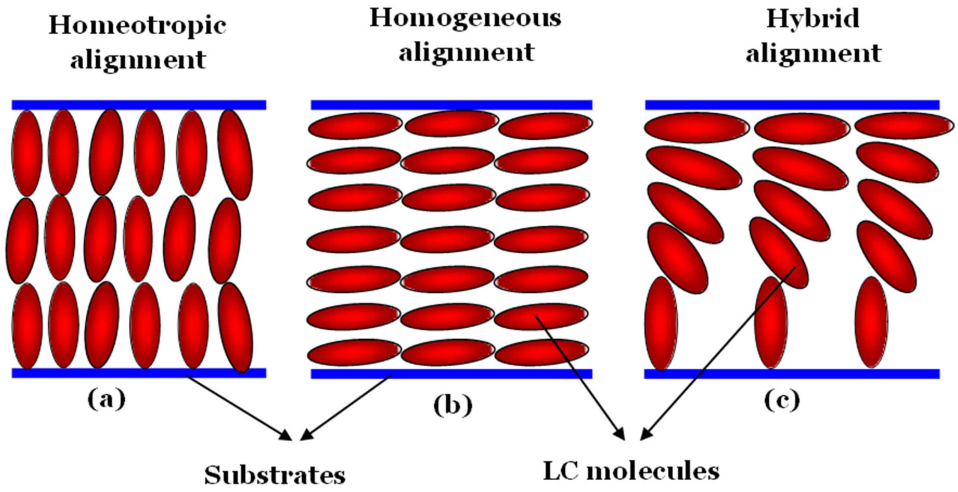
Figure 4.
Chemical structure of POSS NPs. Reproduced from [144].
Figure 4.
Chemical structure of POSS NPs. Reproduced from [144].
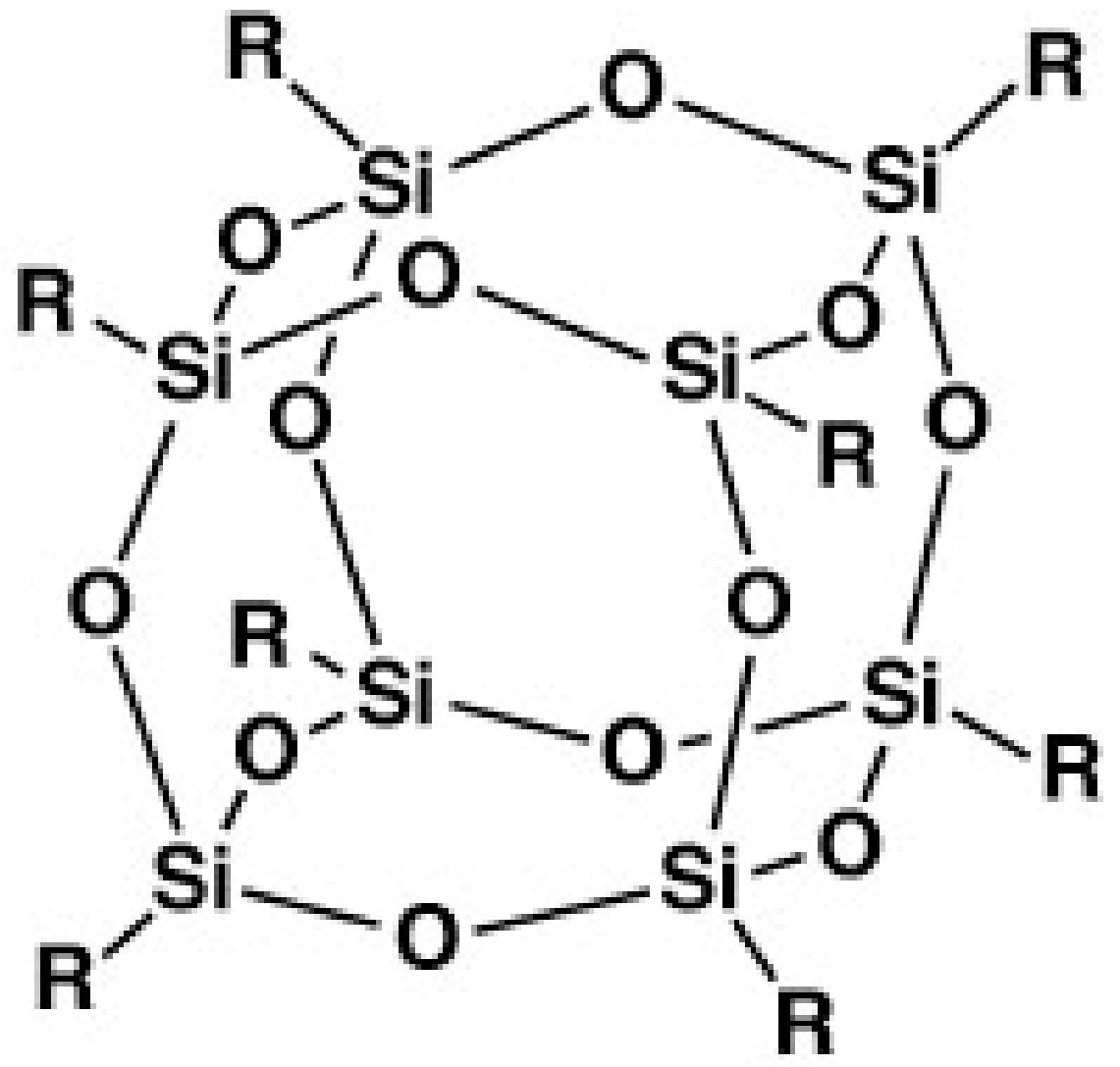
Figure 5.
Structures of sample cells (a) containing a mixture of E7 and POSS NPs with the lower glass substrate homogeneously aligned, (b) containing pure E7 with the lower and upper glass substrates homogeneously and vertically aligned, respectively, and (c) containing pure E7 with only one homogeneous alignment layer and without using any vertical alignment layer. Reproduced with permission from [134]. Copyright 2007 AIP Publishing.
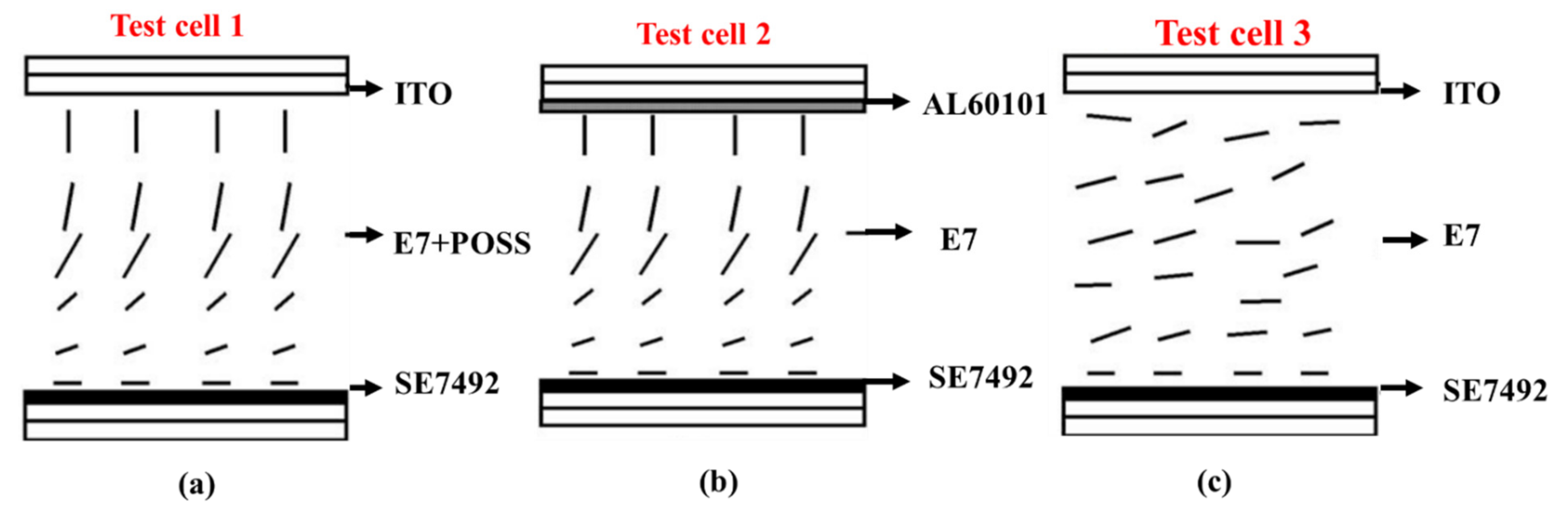
Figure 6.
The variation in the pretilt angle in degrees with changes in the concentration of POSS NPs in the polyimide layer for two different rubbing depths. Reproduced from [135].
Figure 6.
The variation in the pretilt angle in degrees with changes in the concentration of POSS NPs in the polyimide layer for two different rubbing depths. Reproduced from [135].

Figure 7.
Variations in the contact angle of a distilled water droplet on a POSS-aligned E7 mixture and its surface energy as a function of the concentrations of POSS NPs in the polyimide layer. Reproduced from [135].
Figure 7.
Variations in the contact angle of a distilled water droplet on a POSS-aligned E7 mixture and its surface energy as a function of the concentrations of POSS NPs in the polyimide layer. Reproduced from [135].

Figure 8.
Polarizing optical micrographs of an unaligned LC cell filled with (a) pure 5CB, (b) 5CB incorporated with 0.01 wt.% NiNSs, (c) cholesteric LC mixture doped with 0.01 wt.% NiNSs, (d) 5CB filled with 0.01 wt.% NiNBs in the bright field, (e) 5CB filled with 0.01 wt.% NiNBs in the dark field and (f) the same cholesteric LC mixture now doped with 0.01 wt.% NiNBs. Reproduced with permission from [141]. Copyright 2011 Wiley.
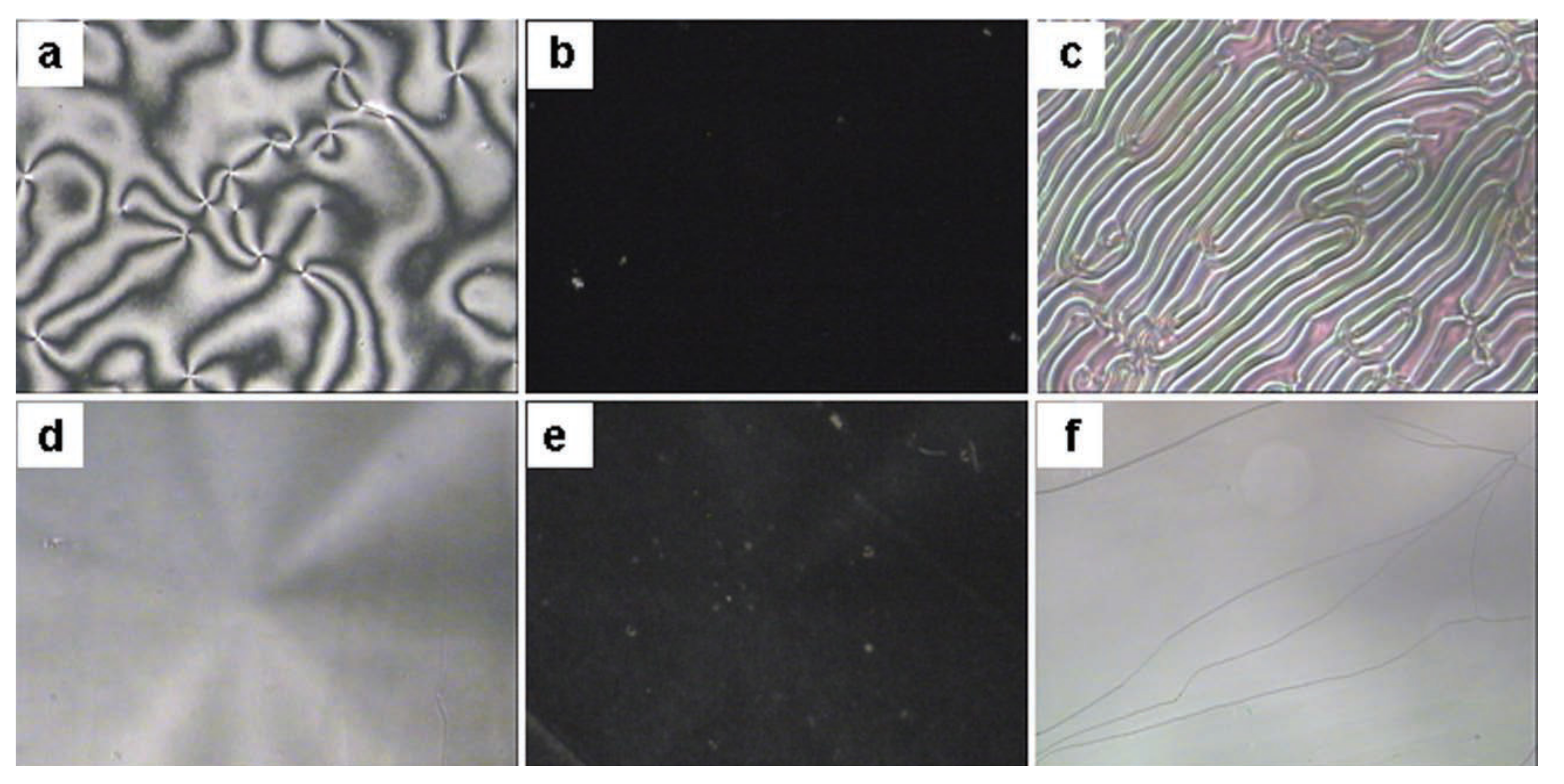
Figure 9.
(a) The procedure involved in the fabrication of an LC microlens using the NPs-induced vertical alignment technique. (b) Overall configuration of LC molecules due to the localized microdropping of POSS NPs on a homogeneously aligned polyimide film. Reproduced from [158].
Figure 9.
(a) The procedure involved in the fabrication of an LC microlens using the NPs-induced vertical alignment technique. (b) Overall configuration of LC molecules due to the localized microdropping of POSS NPs on a homogeneously aligned polyimide film. Reproduced from [158].

Figure 10.
Image formed by a hybrid-aligned LC microlens under different applied voltages: (a) the original image of the card as an object, (b) 0 V, (c) 0.5 Vrms, (d) 1 Vrms, (e) 2 Vrms and (f) 3 Vrms. Reproduced from [158].
Figure 10.
Image formed by a hybrid-aligned LC microlens under different applied voltages: (a) the original image of the card as an object, (b) 0 V, (c) 0.5 Vrms, (d) 1 Vrms, (e) 2 Vrms and (f) 3 Vrms. Reproduced from [158].

Figure 11.
An experimental setup to analyze the voltage-dependent behavior of a hybrid-aligned LC microlens. Reproduced from [158].
Figure 11.
An experimental setup to analyze the voltage-dependent behavior of a hybrid-aligned LC microlens. Reproduced from [158].

Figure 12.
Field-induced transformation in a hybrid-aligned LC microlens due to changes in the applied voltage. Reproduced from [158].
Figure 12.
Field-induced transformation in a hybrid-aligned LC microlens due to changes in the applied voltage. Reproduced from [158].

Publisher’s Note: MDPI stays neutral with regard to jurisdictional claims in published maps and institutional affiliations. |
© 2022 by the authors. Licensee MDPI, Basel, Switzerland. This article is an open access article distributed under the terms and conditions of the Creative Commons Attribution (CC BY) license (https://creativecommons.org/licenses/by/4.0/).
Share and Cite
MDPI and ACS Style
Prakash, J.; Kumar, A.; Chauhan, S. Aligning Liquid Crystal Materials through Nanoparticles: A Review of Recent Progress. Liquids 2022, 2, 50-71. https://doi.org/10.3390/liquids2020005
AMA Style
Prakash J, Kumar A, Chauhan S. Aligning Liquid Crystal Materials through Nanoparticles: A Review of Recent Progress. Liquids. 2022; 2(2):50-71. https://doi.org/10.3390/liquids2020005
Chicago/Turabian StylePrakash, Jai, Akash Kumar, and Shikha Chauhan. 2022. "Aligning Liquid Crystal Materials through Nanoparticles: A Review of Recent Progress" Liquids 2, no. 2: 50-71. https://doi.org/10.3390/liquids2020005