
Article

Hydro-Mechanical Performance Framework for Performance-Based Quality Control of Excavated-Material Fills

by
Carlos Buenahora
1,*,
Fabián Castellanos
1 and
Antonio Martínez-Graña
2
1
IG+ Ingeniería S.A.S, Floridablanca, Santander 681004, Colombia
2
Department of Geology, University of Salamanca, 37008 Salamanca, Spain
*
Author to whom correspondence should be addressed.
Geotechnics 2026, 6(4), 99; https://doi.org/10.3390/geotechnics6040099
Submission received: 28 August 2026 / Revised: 23 September 2026 / Accepted: 29 September 2026 / Published: 3 October 2026

Abstract

Excavated-Material Disposal Areas (ZODMES) exhibit high physical, hydraulic, and mechanical variability, whereas quality control typically focuses on compaction without verifying whether the shear-strength parameters adopted in design remain representative. This study develops a Hydro-Mechanical Performance Framework that integrates matric suction, stiffness measured with a lightweight deflectometer, shear strength, and slope stability to establish performance-based quality control. The framework was validated through laboratory and field testing, characterization of the soil-water characteristic curve, infiltration modeling, limit-equilibrium analysis, Monte Carlo simulations, and sensitivity analysis. Target moduli of 76 and 68 MPa were established for the two soil types evaluated. The 1.5H:1.0V slope geometry exhibited the best performance, increasing the pseudostatic factor of safety from 1.411 to 1.674 and reducing the probability of failure from 3.40% to 0.10% relative to the 1.0H:1.0V slope. Cohesion was the parameter with the greatest influence on stability (R2 = 0.91–0.93). The framework provides a quantitative procedure for linking field hydro-mechanical conditions to design assumptions; it does not replace conventional geotechnical testing and requires material-specific calibration.

1. Introduction

The construction of roads, tunnels, railway systems, deep foundations, and other infrastructure works generates large volumes of excavated soil and rock. Although project planning seeks to balance cut and fill volumes, this balance is rarely achieved, particularly in underground works and mountainous highway corridors. The resulting surplus must therefore be reused within the project, beneficially used in other works, or placed in facilities prepared for that purpose. In Colombia, these facilities are known as Excavated-Material Disposal Areas (ZODMES, from the Spanish acronym) [1] and are an essential component of infrastructure projects. The scale of this challenge extends beyond the national context. In the European Union, construction and demolition waste accounts for approximately 40% of the waste generated [2], while excavated soil and rock represented nearly 23% of the total produced in 2020 [3]. These figures show that excavated-material management is one of the construction sector’s largest material flows; improper disposal increases costs, environmental impacts, and risks to deposit stability. In this context, ZODMES should be conceived as geotechnical structures built by progressively placing and compacting excavated materials. Although circular-economy strategies promote reuse whenever technically and environmentally feasible [4], a substantial fraction will continue to require permanent disposal. The challenge is therefore to ensure that these deposits are designed and constructed using verifiable geotechnical criteria that secure their long-term stability and performance.
For the purposes of this study, a ZODME is defined as an engineered earth structure intended for the controlled placement, spreading, and compaction of surplus excavated soil and rock under specified geometric, drainage, and geotechnical criteria. This definition distinguishes a ZODME from uncontrolled spoil disposal and emphasizes that its performance must be evaluated as that of a constructed geotechnical fill.
From a geotechnical standpoint, the main challenge in designing and constructing ZODMES is the pronounced heterogeneity of the materials used. These deposits receive materials from different excavation faces, producing mixtures of sand, silt, clay, gravel, and rock fragments with variable physical, hydraulic, and mechanical properties. This heterogeneity complicates the definition of representative effective cohesion (c′) and effective friction angle (φ′), thereby increasing uncertainty in stability analyses [5]. In engineering practice, this uncertainty is commonly addressed using parameters obtained from limited laboratory campaigns, empirical correlations, or conservative judgment, which may lead either to overdesigned solutions or to estimates that poorly represent the deposit’s actual behavior [6]. The limitation persists during construction because conventional quality-control procedures primarily verify the degree of compaction through field-density tests but cannot demonstrate that the shear-strength parameters used in design remain representative of the as-built material [7]. This issue is particularly important in partially saturated materials, where changes in moisture content modify matric suction, alter effective stress, and produce changes in stiffness and shear strength [8]. Consequently, the central challenge is not merely to control compaction, but to establish an objective procedure for verifying during construction that the shear-strength parameters used in design adequately represent the fill’s hydro-mechanical behavior.
Research on heterogeneous fills has advanced along three main lines: quantifying uncertainty in geotechnical parameters, developing quality-control tools for compaction, and investigating the hydro-mechanical behavior of partially saturated soils. Several authors have shown that uncertainty in geotechnical parameters depends on the material’s natural variability, sampling representativeness, and the limitations of laboratory testing, and have recommended probabilistic approaches to reduce subjectivity when selecting design parameters. In parallel, the LWD has become an established tool for evaluating near-surface stiffness and supplementing compaction control. Under this approach, its response can be compared with a target modulus obtained in the laboratory from the reference compaction condition defined by the Proctor test [9], thereby enabling field verification that the stiffness achieved by the material is compatible with that condition [10]. Nevertheless, its application remains focused on construction control rather than on validating the shear-strength parameters used in stability analyses. Unsaturated-soil mechanics have also shown that matric suction modifies soil effective stress, stiffness, and shear strength. The developments of Fredlund [8], van Genuchten [11], and Fredlund and Xing [12] established the conceptual and mathematical basis for describing these relationships through soil-water characteristic curves (SWCCs). However, these advances have remained largely within experimental characterization and numerical modeling, with limited application to fill quality control. Recent research has reinforced the need to consider these hydraulic and mechanical processes jointly. Li et al. (2023) showed that non-stationary and spatially variable saturated hydraulic conductivity can materially affect rainfall infiltration, slope stability, and failure probability in unsaturated slopes [13]. Recent LWD studies likewise confirm that measured stiffness is sensitive to moisture state and testing conditions, supporting interpretation of LWD results together with water content rather than as an isolated compaction indicator [14]. Recent studies provide more direct evidence for these coupled effects in engineered and unsaturated earth structures. Costa et al. (2023) demonstrated that transient rainfall can modify the probability of failure of unsaturated slopes when hydraulic and mechanical variables are treated probabilistically [15]. Zheng et al. (2024) showed for compacted unsaturated embankments that rainfall-induced wetting reduces suction and produces coupled deformation and shear-strain accumulation, confirming that hydraulic state cannot be separated from mechanical performance in compacted fills [16]. Gu et al. (2024) further showed that field observations and spatially variable soil properties can be incorporated into probabilistic unsaturated-slope assessment to update parameter uncertainty and reliability predictions under rainfall [17]. Together, these studies support treating compacted fills as evolving hydro-mechanical systems and explicitly representing uncertainty rather than relying exclusively on fixed deterministic parameters.
The reviewed literature revealed no studies that simultaneously integrate matric suction, LWD-measured stiffness, shear-strength parameters, and stability analyses within a single methodological framework. A gap therefore persists between laboratory geotechnical characterization, field quality control, and validation of stability models, requiring designers, contractors, and construction supervisors to support technical decisions with criteria that are partly subjective or excessively conservative. The underlying hypothesis is that the combination of matric suction, LWD-measured stiffness, and shear-strength parameters can represent the hydro-mechanical behavior of the compacted material and provide a representative indicator for objectively substantiating the design parameters. Based on this hypothesis, this study develops and validates a Hydro-Mechanical Performance Framework for geotechnical characterization and performance-based quality control of ZODMES.
This unified strategy overcomes the traditional methodological separation by establishing experimental relationships between laboratory-test responses (modified Proctor, direct shear, and matric suction) and in situ geomechanical stiffness measurements. To validate the overall consistency of the proposed approach against material variability, the experimental framework was coupled with a numerical-modeling architecture. This computational phase integrated numerical simulations of unsaturated infiltration to evaluate pore-pressure evolution under climatic events, slope-stability analyses using limit-equilibrium methods, and probabilistic modeling through Monte Carlo simulations and global sensitivity analysis. Through this hybrid methodological design, the study demonstrates that the mechanical behavior of compacted soil is intrinsically linked to its hydraulic condition and provides a quantitative, reproducible protocol that can support optimization of disposal-fill slope geometry without compromising the structure’s safety.

2. Materials and Methods

2.1. Proposed Methodology

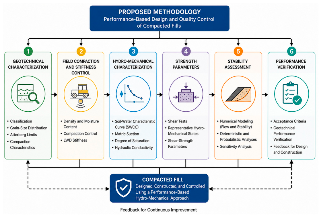
This study proposes an integrated hydro-mechanical framework for the design, construction, and performance-based quality control of compacted fills built with surplus excavation materials, including ZODMES. The methodology combines laboratory geotechnical characterization, LWD stiffness measurements, material hydraulic characterization, and numerical modeling in an integrated procedure for evaluating the fill’s geotechnical performance.
Although the methodology was developed and evaluated in a land-development project constructed through cut-and-fill operations, the heterogeneity, excavation, transport, reuse, and compaction conditions of the materials are representative of those encountered in ZODMES and other fills constructed with excavated materials. The procedure therefore constitutes a methodological framework that may be adapted to other compacted earth structures (dams, railway embankments, and industrial platforms), subject to calibration for the project-specific materials.
The methodology comprises six main stages:
  • Geotechnical characterization of the materials;
  • Evaluation of compaction and stiffness using the LWD;
  • Hydro-mechanical characterization by determining matric suction and the soil-water characteristic curve (SWCC);
  • Determination of shear-strength parameters;
  • Infiltration modeling and stability evaluation using deterministic and probabilistic analyses;
  • Integrated evaluation of fill performance.
In this study, ZODMES are regarded as compacted-fill structures composed of surplus excavation materials; however, the term compacted fill is used more broadly to include other earth structures built through controlled spreading and compaction. The two concepts are therefore not equivalent, although they share construction processes and geotechnical mechanisms that permit transfer of the methodological framework following project-specific calibration.
Figure 1 presents the overall framework and the interactions among its components, while the following sections describe the case study, experimental program, and procedures used for validation.

2.2. Case Study

The methodology was validated during implementation of a land-development project involving cut-and-fill operations in which all excavated materials were reused to construct compacted fills. This setting allowed the methodology to be evaluated under actual construction conditions through geotechnical characterization of the materials, compaction control, LWD stiffness measurements, and verification of the fill’s hydro-mechanical behavior.
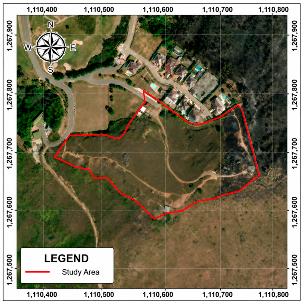
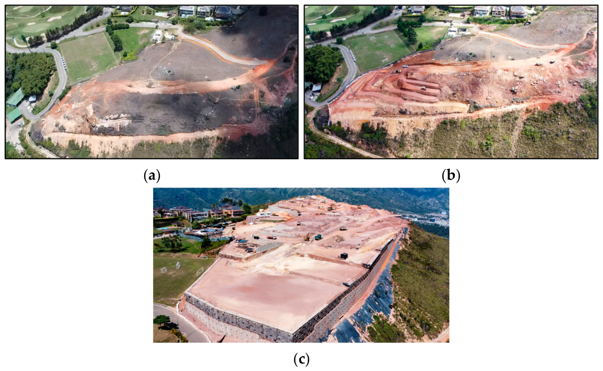
The project is located in the Ruitoque condominium, in the municipality of Piedecuesta, Santander, Colombia (Figure 2), on materials of the Girón Formation (Jg) [18], which consists of medium- to coarse-grained, locally conglomeratic sandstones. The case study covers an area of approximately 40,000 m2, where nearly 70,000 m3 of excavation and fill were undertaken to construct fills ranging from 2.5 to 17.0 m in height. Construction involved placing and compacting successive 30 cm thick lifts with a 12 t vibratory roller, reproducing the operating conditions commonly used for infrastructure fills (Figure 3).
Experimental validation was conducted throughout the different stages of fill construction by integrating laboratory results, field measurements, and numerical analyses within the proposed methodological procedure. Although the case study was a land-development project rather than a conventional ZODME, the comprehensive management of the excavated materials reproduced the fundamental stages associated with such structures, including characterization, transport, placement, and compaction. The project therefore provides a representative setting in which to validate the approach and evaluate its potential application to both ZODMES and other compacted infrastructure fills.

2.3. Experimental Program

The proposed procedure was validated through an integrated experimental program combining laboratory tests, field measurements, and hydro-mechanical characterization of the material during the different stages of fill construction. The program was designed to obtain the information required to characterize the physical, hydraulic, and mechanical properties of the compacted material and to evaluate their influence on the fill’s geotechnical performance.
Geotechnical characterization included determination of the material’s index and compaction properties through classification tests, particle-size analysis, Atterberg limits, and modified Proctor tests. Thin-walled tube samples were subsequently recovered from the same areas in which LWD measurements were performed. Specimens were trimmed from these samples for consolidated–drained direct shear tests to determine the effective parameters corresponding to the in-situ material state. Hydro-mechanical characterization included determination of the soil-water characteristic curve (SWCC) [12] by the filter-paper method, thereby establishing the relationship between matric suction and degree of saturation.
During fill construction, a quality-control program based on field-density and moisture-content measurements was supplemented with LWD tests performed using a Dynatest Light Weight Deflectometer (Dynatest A/S, Ballerup, Denmark) in accordance with ASTM E2583 [19] to evaluate the near-surface stiffness of the compacted material. Field tests used a 300 mm diameter circular loading plate and a drop height of 23 in., yielding the field surface modulus (EField). In parallel, a laboratory reference surface modulus (ELab) was determined by applying the LWD to specimens compacted in the modified Proctor mold. Comparison of EField and ELab made it possible to determine whether the stiffness achieved in the field was compatible with the reference compaction condition defined for each material. The resulting information was subsequently incorporated into the stability, infiltration, probabilistic, and sensitivity analyses used to validate the proposed methodological procedure.
Material shear strength was determined through consolidated–drained (CD) direct shear tests performed in accordance with INV E-154-13 [20]. The specimens were trimmed directly from undisturbed thin-walled tube samples recovered from the same areas where LWD measurements were performed, thereby preserving the in situ condition of the compacted fill as far as practicable during specimen preparation. Circular specimens were approximately 50.76 mm in diameter and 21.7 mm in height, with an initial area of 20.236 cm2. Normal stresses of 45, 90, and 180 kPa were applied in each test series, and shearing was conducted at a horizontal displacement rate of 0.1 mm/min. Shear stress was calculated using the corrected specimen area, and the maximum shear stress recorded during each test was adopted as the peak-failure criterion for defining the Mohr–Coulomb envelope and obtaining the corresponding effective cohesion (c′) and friction angle (φ′).
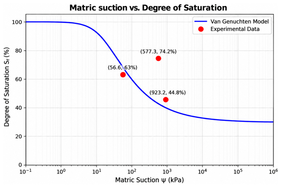
Matric suction was determined using the filter-paper method in accordance with INV E-159-13 [21], using Whatman No. 42 filter paper and an equilibration period of 7 days. For each of the three sampled material states, five independent filter-paper determinations were obtained and averaged, yielding mean matric-suction values of 56.6, 577.3, and 923.2 kPa at degrees of saturation of 63.0%, 74.2%, and 44.8%, respectively. The individual determinations within each material state were retained as valid laboratory measurements; therefore, the 577.3 kPa point is not interpreted here as an experimental error or an anomalous replicate. However, this point was not used to calibrate the adopted SWCC because its combination of higher degree of saturation (74.2%) and substantially higher suction than the 63.0% saturation state (56.6 kPa) was incompatible with the monotonic water-retention trend required by the van Genuchten representation used in the numerical model. The point was retained and reported transparently as experimental evidence, while the SWCC calibration used the two experimental states consistent with the monotonic trend. Laboratory temperature and ambient relative humidity during equilibration were not recorded in the test report; this limitation is explicitly acknowledged and no unrecorded environmental conditions were assumed retrospectively.
Table 1 summarizes the experimental program and the principal variables considered in the study.
More than 1200 LWD tests were performed for the project; however, 20 points, corresponding to the same locations at which direct shear tests were conducted, were selected for this analysis to establish a direct comparison between field-measured stiffness and shear-strength parameters.

2.4. Hydro-Mechanical Integration for Characterizing Fill Performance

The behavior of a compacted fill is governed by the interaction of hydraulic and mechanical variables that evolve during construction and throughout the structure’s service life. Moisture content controls the material’s matric-suction state, while compaction modifies its internal structure and, consequently, its stiffness and shear strength. These variables act in a coupled manner and define the fill’s hydro-mechanical state.
In the proposed methodology, matric suction represents the energy state of pore water and is characterized through the soil-water characteristic curve (SWCC), which describes the relationship between water content and suction. Stiffness is determined with the LWD, whose deformation response reflects the material’s mechanical behavior under actual construction conditions. The experimentally obtained shear-strength parameters complete this characterization and provide the basis for the stability analyses.
Integrating these variables links the material’s hydraulic condition to its mechanical response and enables joint evaluation of fill behavior during design, construction, and numerical analysis.

2.5. Numerical Modeling and Performance Evaluation

To evaluate fill behavior under representative service conditions, the parameters determined through the experimental program were incorporated into an integrated numerical-modeling scheme that addressed hydraulic response, stability, and the uncertainty associated with the fill’s geotechnical behavior. This process constitutes the framework-validation stage because it transforms laboratory and field information into objective performance indicators that support design and quality-control decisions.
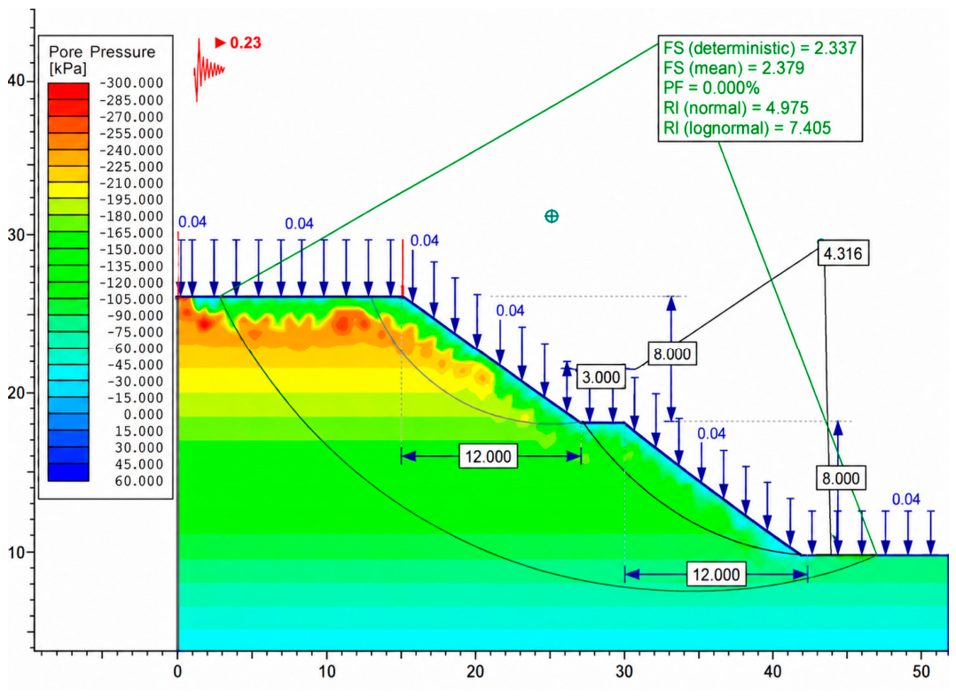
The hydraulic assessment was performed using an unsaturated transient-flow model [24]. The SWCC was represented with the van Genuchten relationship using a residual degree of saturation of 30%, α = 0.05 kPa−1, n = 1.5, and m = 1 − 1/n = 0.3333. The hydraulic-conductivity function was derived from the SWCC through the Mualem–van Genuchten formulation, with a pore-connectivity parameter l = 0.5 and a saturated hydraulic conductivity Ks = 1 × 10⁻⁶ m/s. The latter was adopted on the basis of material type rather than obtained from a direct permeability test. The infiltration scenario applied a constant rainfall flux of 0.04 m/h (40 mm/h) for 2 h, equivalent to 80 mm of cumulative rainfall. The model was initialized in an unsaturated dry state; during the transient analysis, Slide v6.0 calculated the evolution of pore-water pressure, while the corresponding suction response was governed by the adopted SWCC and hydraulic constitutive functions. Hydraulic and stability responses were evaluated at 0.2, 1.0, and 2.0 h. The resulting pore-pressure fields were subsequently coupled with Spencer limit-equilibrium analyses to determine the factor of safety for the geometries and hydraulic conditions evaluated. A horizontal seismic coefficient kh = 0.23 was adopted for the pseudostatic analyses based on the study site’s location and identified soil type. To incorporate the variability inherent in excavated materials, probabilistic Monte Carlo simulations were performed using normal probability distributions and 1000 iterations in which the soil parameters were varied. These simulations yielded the factor-of-safety distribution and probability of failure for each scenario. A complementary sensitivity analysis identified the variables with the greatest influence on fill stability and the parameters requiring tighter control during construction.
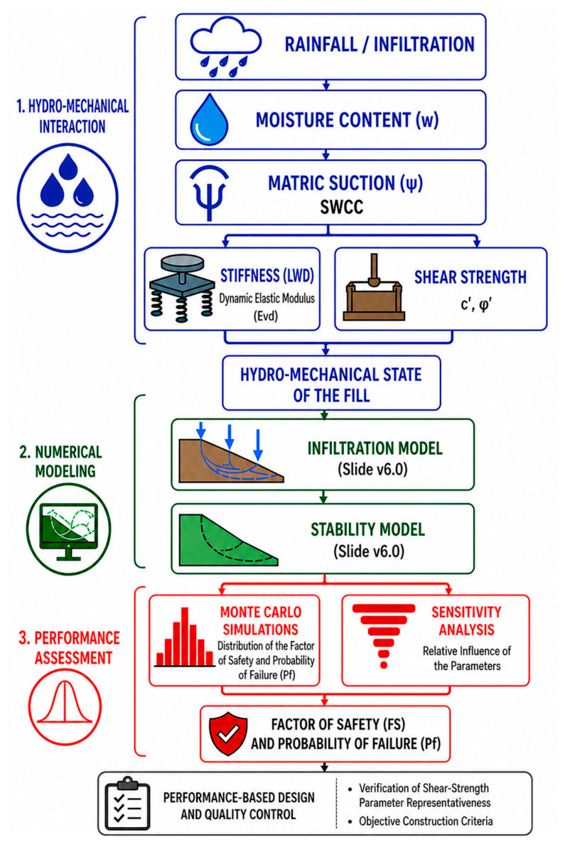
Figure 4 summarizes the integrated scheme developed in this study and shows how hydraulic variables (moisture content and matric suction) and mechanical variables (stiffness and shear strength) converge to define the fill’s hydro-mechanical state, which supplies the input for numerical modeling and subsequent evaluation of geotechnical performance. This approach makes it possible to verify the validity of the shear-strength parameters used in design and to establish acceptance criteria grounded in the fill’s actual behavior, thereby moving beyond conventional procedures based solely on degree of compaction.

3. Results

3.1. Geotechnical Characterization of the Materials

As an initial stage, the materials used to construct the fill were geotechnically characterized to establish their classification, compaction conditions, and shear-strength properties before hydro-mechanical evaluation. This stage identified the inherent variability of the excavated materials and defined the reference parameters used in the subsequent stages of the study.
Physical characterization comprised determination of the particle-size distribution and Atterberg limits, allowing the materials to be classified according to the Unified Soil Classification System (USCS). The results show materials with different proportions of coarse and fine fractions, representative of the mixtures generated during excavation and fill-placement operations. This heterogeneity confirms one of the principal difficulties in designing fills constructed with surplus excavation materials, in which spatial variability limits the definition of a single set of shear-strength parameters for the entire structure. Optimum compaction conditions were subsequently determined through modified Proctor tests, which established the relationship between moisture content and maximum dry density for each material. These results formed the basis of the experimental program and defined the compaction conditions used in the laboratory tests and field verifications. As a complement to the physical characterization, shear-strength parameters were determined by direct shear testing, and hydraulic behavior was assessed through matric-suction tests. Although these results are presented in greater detail in the following sections, obtaining them at this stage provided a consistent set of physical, hydraulic, and mechanical properties for calibrating the methodological framework.
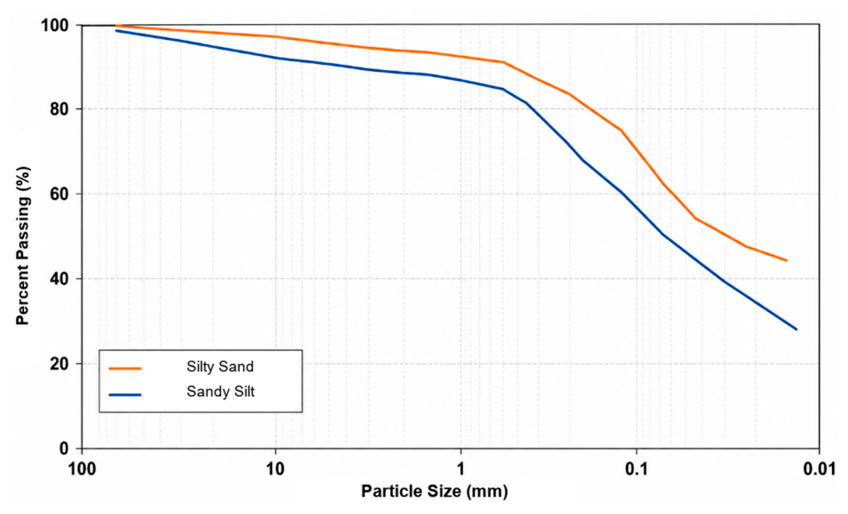
Table 2 presents the results of the geotechnical classification, particle-size distribution curves (Figure 5), and compaction tests for the materials evaluated. Table 3 summarizes the results of the suction tests.

3.2. Hydro-Mechanical Behavior of the Materials

After the physical properties and optimum compaction conditions had been established, the materials’ hydro-mechanical behavior was evaluated by combining matric-suction and shear-strength tests with LWD stiffness measurements. This stage established the relationships among hydraulic state, mechanical response, and stability of the compacted material. Table 4 summarizes the principal experimental results, including the target moduli, SWCC parameters, and correlations developed among moisture content, stiffness, and strength. Table 5 presents the main statistics calculated for each soil parameter.
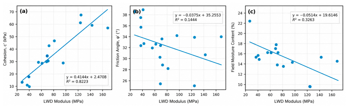
The experimental response showed that the LWD does not represent all strength components equally. Within the statistical dataset used, cohesion had a strong positive relationship with modulus (R2 = 0.8223), whereas the friction angle had a weak relationship (R2 = 0.1444). Moisture content exhibited a negative trend with modulus (R2 = 0.3263), confirming that stiffness must be interpreted jointly with the material’s hydraulic state. These relationships are presented together in Figure 6 and are specific to the materials and compaction conditions evaluated.
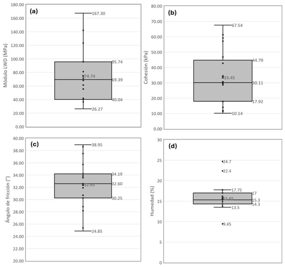
The statistical variability reinforces this interpretation. For the dataset used in the statistical analyses, the LWD modulus had a mean of 74.74 MPa and a standard deviation of 39.46 MPa, while cohesion had a mean of 33.45 kPa and a standard deviation of 18.04 kPa. In contrast, the friction angle was comparatively more stable, with a mean of 32.45° and a standard deviation of 3.89°. Figure 7 shows that fill heterogeneity is expressed more strongly in stiffness and cohesion than in the friction angle.
In parallel, direct shear tests were used to determine the effective shear-strength parameters of samples obtained from the study area. The variability observed in these parameters is consistent with the inherent heterogeneity of excavated materials and confirms the need for procedures that objectively verify their compatibility during construction. The fill’s mechanical response was evaluated through LWD tests performed during construction, yielding stiffness moduli for different project areas and moisture states. The results show substantial variation in the field modulus, reflecting the combined influence of degree of compaction and the material’s hydraulic condition at the time of testing. These measurements were used to establish reference target moduli for quality control, which were subsequently applied to verify the performance of compacted lifts.
Figure 8 integrates the principal experimental results obtained during this stage, including hydraulic characterization through the SWCC. Taken together, these results demonstrate that material stiffness depends not only on the percentage of compaction achieved but also on its hydro-mechanical state, thereby providing the experimental basis for the geotechnical performance assessment presented in the following section.

3.3. Geotechnical Performance Evaluation

The information obtained during experimental characterization was incorporated into an integrated numerical-modeling scheme to evaluate the fill’s hydraulic and mechanical behavior under different operating conditions. This procedure made it possible to analyze the influence of infiltration on the material’s hydro-mechanical state and quantify its effect on stability using deterministic and probabilistic approaches. Unsaturated-flow modeling represented the spatial evolution of moisture content, matric suction, and pore pressures within the fill. The results support the finding that infiltration progressively modifies the material’s hydraulic state, reducing matric suction and, consequently, its contribution to mobilized soil strength. This behavior confirms that fill stability depends not only on the strength properties determined in the laboratory but also on the evolution of hydraulic conditions over its service life. The shear-strength parameters obtained from direct shear tests were first incorporated into deterministic and probabilistic limit-equilibrium stability analyses. Comparing the evaluated configurations identified the geometry with the best geotechnical performance in terms of factor of safety and probability of failure. The infiltration analysis was then performed for the selected configuration to evaluate the evolution of moisture content, matric suction, and pore pressures and to verify their effect on fill stability. To incorporate the uncertainty inherent in the geotechnical parameters, probabilistic Monte Carlo simulations were performed [6]. These simulations estimated the distribution of the factor of safety and the probability of failure for the different scenarios, providing a more robust assessment of design reliability than a purely deterministic approach.
Finally, the sensitivity analysis identified the variables with the greatest influence on fill stability and provided an objective ranking of the parameters that control system behavior. These results are essential for guiding both design and quality control by focusing characterization and monitoring efforts on the variables that actually govern geotechnical performance.
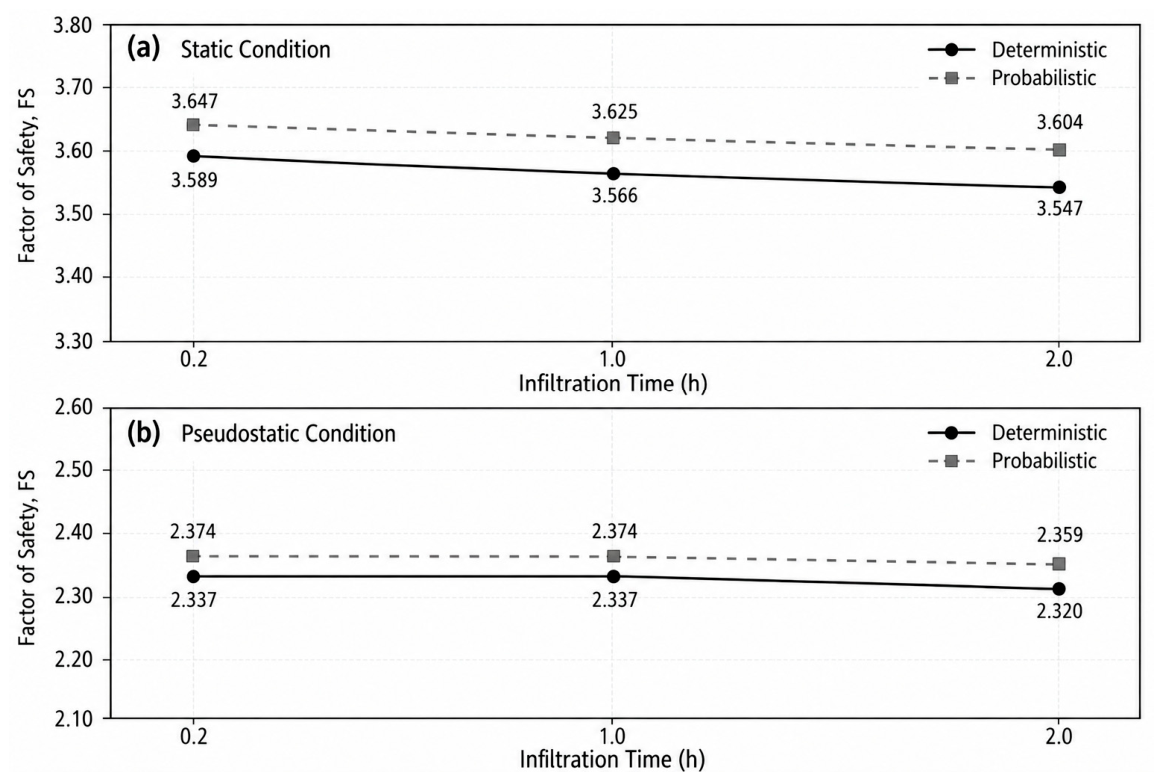
Figure 9 and Figure 10 summarize the fill’s hydraulic response, while Table 6 presents the corresponding infiltration-model results.
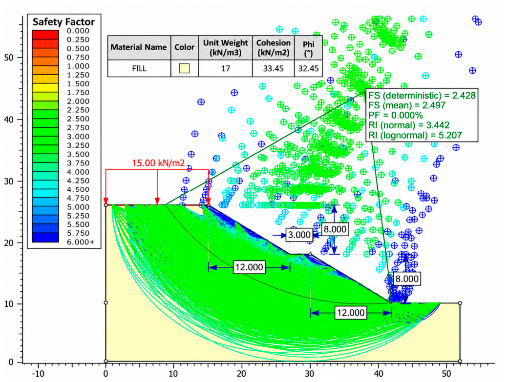
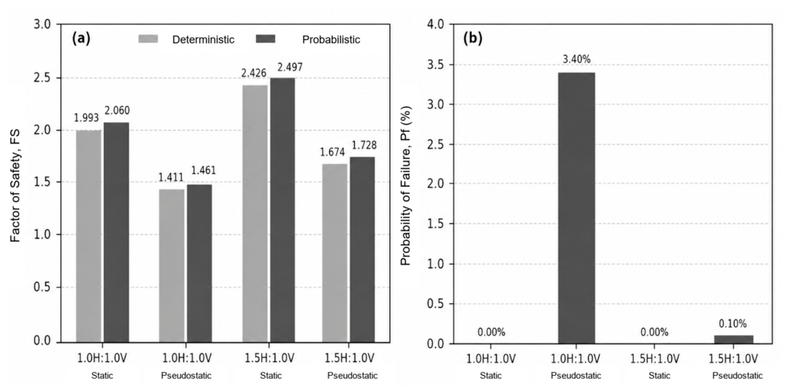
Figure 11 presents an example of the probabilistic stability analysis, Table 7 summarizes the deterministic and probabilistic stability-analysis results, and Figure 12 and Figure 13 integrate the reliability results and sensitivity analysis, respectively.
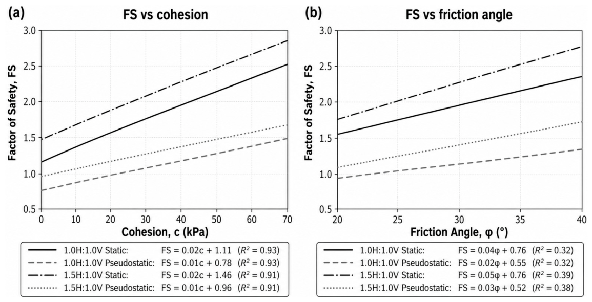
Figure 13 shows that cohesion has a stronger relationship with the factor of safety than the friction angle, indicating that the slope is more sensitive to changes in cohesion.

3.4. Integrated Evaluation of the Proposed Hydro-Mechanical Framework

The experimental results showed substantial variability in the fill’s mechanical properties. The LWD-measured modulus had a mean of 74.74 MPa, a standard deviation of 39.46 MPa, and values ranging from 26.27 to 167.30 MPa. Among the shear-strength parameters, cohesion had a mean of 33.45 kPa and a standard deviation of 18.04 kPa, whereas the friction angle had a mean of 32.45° and a standard deviation of 3.89°. In addition, the relationship between moisture content and stiffness yielded target moduli of 76 MPa for the silty sand and 68 MPa for the sandy silt.
Incorporating these parameters into the stability analyses enabled a quantitative comparison of the two geometries evaluated, 1.0H:1.0V and 1.5H:1.0V, under the same pseudostatic scenario. Deterministic and probabilistic analyses were performed for each geometry. The deterministic factor of safety increased from 1.411 for the 1.0H:1.0V slope to 1.674 for the 1.5H:1.0V slope, while the probabilistic factor of safety increased from 1.461 to 1.728. Concurrently, the probability of failure decreased from 3.40% to 0.10%. The sensitivity analysis further showed that cohesion had the strongest relationship with the factor of safety, with R2 values of 0.91–0.93, whereas the R2 values for the friction angle ranged from 0.32 to 0.39.
Finally, infiltration analyses for the 1.5H:1.0V slope showed a progressive but limited reduction in the factor of safety over the 2 h period evaluated. Under static conditions, the deterministic factor of safety decreased from 3.589 to 3.547; under pseudostatic conditions, it decreased from 2.337 to 2.320. The small magnitude of this change may be associated with the substantial fine content and low hydraulic conductivity of the evaluated materials, which limited penetration of the wetting front during a short-duration event. Consequently, the analyzed 2 h rainfall event was insufficient to cause significant changes in global stability under the scenario considered, although it did reveal the downward trend in the factor of safety as infiltration progressed.

4. Discussion

4.1. Integration of Hydro-Mechanical Behavior and Comparison with the Literature

The results confirm that the difficulty of characterizing fills constructed with excavated materials arises not only from the limited number of tests but also from the physical and construction-related variability of the deposit itself. The materials studied included silty sands, low-plasticity clays, and low-plasticity silts, with a fine clayey–silty matrix that governs overall hydraulic behavior. This composition reduces fill permeability and increases sensitivity to changes in moisture content; stiffness and strength, therefore, should not be interpreted as constant properties independent of hydraulic state.
This interpretation is consistent with Masín (2015), who stated that geotechnical uncertainty arises simultaneously from the natural variability of materials, sampling representativeness, and experimental limitations [5]. In the case analyzed, this uncertainty is expressed not only among different soil types but also within a single material because of spatial variations in moisture content, densification, and compaction energy. Adopting a single cohesion, friction angle, or stiffness modulus to represent the entire fill may therefore conceal important construction-related differences and lead to oversimplified interpretations of its behavior.
The wide dispersion of the LWD-measured modulus provides direct evidence of this heterogeneity. The modulus had a mean of 74.74 MPa and a standard deviation of 39.46 MPa, with measured values ranging from 26.27 to 167.30 MPa. Values below 30 MPa were associated with areas that were difficult for compaction equipment to access, such as edges, corners, and zones adjacent to slopes; moduli above 120 MPa were associated with areas subjected to repeated dump-truck and heavy-vehicle traffic, where localized densification occurred. These results show that the LWD can do more than determine whether a lift meets an acceptance value: it can identify spatial discontinuities in the construction process that may not be adequately captured by a small number of conventional density tests.
Quantitatively, the variability was not uniform among the measured mechanical parameters. The coefficient of variation (CoV) was 0.528 for the LWD modulus and 0.539 for cohesion, compared with only 0.120 for the friction angle. The corresponding P10-P90 intervals were 36.74–127.84 MPa for modulus, 11.84–59.59 kPa for cohesion, and 27.62–37.72° for friction angle. Thus, modulus and cohesion exhibited approximately 4.4–4.5 times the relative variability of friction angle. These statistics quantify the heterogeneity observed across the 20 colocated evaluation points; they describe variability among sampled locations but should not be interpreted as a geostatistical spatial-correlation model because no variogram or random-field structure was derived in this study.
However, modulus dispersion cannot be attributed exclusively to differences in compaction. The observed negative relationship between moisture content and modulus indicates that stiffness increases as material moisture content decreases [25,26]. This trend supports the need to interpret LWD measurements together with the hydraulic state at the time of testing. A high modulus may reflect greater densification, but it may also result from a temporary state of higher suction; conversely, a low modulus may be associated either with inadequate compaction or with high moisture content. Using the LWD in isolation could therefore lead to acceptance or rejection of a lift without adequately distinguishing the cause of its mechanical response. The moderate sensitivity of modulus to moisture content indicates that other variables account for a substantial proportion of its variation. This result is consistent with the role attributed to moisture content in previous studies of LWD applications, particularly those of Kavussi et al. [9] and Buenahora-Ballesteros et al. [10]. The present study extends that application by linking stiffness to matric suction, shear-strength parameters, and global stability. Its contribution is therefore not to demonstrate again that water content affects the LWD-measured modulus, but to incorporate this dependence into a procedure for experimentally substantiating the parameters used in design.
This interpretation is also supported by recent LWD research. Kuttah (2023) demonstrated that moisture content, applied load, and testing configuration can alter LWD response in compacted geomaterials [14]. More recently, Guo et al. (2026) reported pronounced moisture sensitivity in LWD modulus and deflection across laboratory, test-pit, and field scales [27]. These findings reinforce the present framework’s requirement that stiffness be interpreted together with moisture and hydro-mechanical state rather than used as a stand-alone surrogate for strength.
Cohesion was the most variable shear-strength parameter, with a mean of 33.45 kPa and a standard deviation of 18.04 kPa. In the present case, this dispersion is interpreted as reflecting local differences in fine content, dry density, soil fabric, and hydraulic state. In compacted unsaturated soils, these variables modify particle arrangement, interparticle contacts, and the stress state of the fine-grained matrix [8]. Accordingly, the comparatively larger variation in c′ is interpreted here as a material- and state-dependent response rather than as evidence of a universal causal relationship.
The comparatively small variation in friction angle is mechanically consistent with the different roles of soil fabric in the two strength components. Within the range of materials and compaction states investigated, changes in fine content, moisture, and dry density can substantially modify the arrangement and bonding of the fine-grained matrix and therefore the intercept of the shear-strength envelope, while the frictional component remains more strongly governed by particle-to-particle sliding, interlocking, and the mineralogical/granular skeleton. Accordingly, the weak modulus–φ′ relationship observed here should not be interpreted as evidence that density or fines never influence friction angle; rather, their influence was comparatively limited over the range represented by this case study. This distinction is important because the LWD–cohesion relationship is an empirical association between indicators responding to the as-built state, not proof of a direct causal law.
The proportional relationship identified between cohesion and stiffness modulus is consistent with this explanation. An increase in the LWD-measured modulus provides indirect evidence of a denser, stiffer state in which effective interparticle contact increases and the cohesive component is strengthened. Nevertheless, this relationship must be understood as an empirical correlation valid for the materials and conditions evaluated, not as a universal equation for estimating cohesion from LWD results, and it should not be automatically extrapolated to other fills. This limitation is fundamental to the rigor of the proposed framework: the LWD may be used as a control and verification indicator only after material-specific calibration through field and laboratory tests. The friction angle behaved differently. Its relationship with modulus was weak, with an essentially horizontal trend, indicating that variations in stiffness did not significantly modify the frictional-resistance mechanism within the range analyzed.
The absence of a strong correlation should not be regarded as a negative result; rather, it distinguishes which strength components are sensitive to the as-built state and which remain relatively stable. In this case, cohesion was more sensitive to densification, fine content, and hydraulic state, whereas the friction angle exhibited a more uniform response. This difference also appears in the stability analyses. For the 1.0H:1.0V and 1.5H:1.0V geometries under both static and pseudostatic conditions, the relationship between cohesion and factor of safety had coefficients of determination ranging from 0.91 to 0.93. By contrast, the relationships between friction angle and factor of safety had R2 values of 0.32–0.39. Within the ranges studied, stability was therefore governed primarily by variability in cohesion. This finding is especially relevant because conservatively assuming zero cohesion may introduce considerable overconservatism and substantially alter the required geometry, whereas adopting a high value without experimental support could overestimate safety.
The geometric comparison confirms the value of combining deterministic analysis with probabilistic evaluation. For the 1.0H:1.0V slope, the deterministic pseudostatic factor of safety was 1.411 and the probability of failure reached 3.40%. Changing the slope ratio to 1.5H:1.0V increased the pseudostatic factor of safety to 1.674 and reduced the probability of failure to 0.10%. This represents an 18.6% increase in factor of safety and an approximately 97% relative reduction in probability of failure. Probabilistic analysis provides insight that is not evident from the factor of safety alone: two designs may satisfy a deterministic criterion yet exhibit different reliability levels because of dispersion in the shear-strength parameters [28,29].
The infiltration models showed gradual reductions in the factor of safety during the 2 h analyzed. Under static conditions, the deterministic value decreased from 3.589 to 3.547; under pseudostatic conditions, it decreased from 2.337 to 2.320. Although these variations did not compromise stability in the evaluated scenario, they demonstrate that hydraulic evolution progressively modifies fill performance and that parameters obtained under an initial condition should not be assumed invariant during wetting [30,31]. Stability models do not validate shear-strength parameters by themselves; their purpose is to verify that the properties obtained through the experimental procedure produce a mechanically consistent response under the hydraulic and geometric conditions considered. Taken together, these results extend the conventional use of the LWD. The literature presents it primarily as a rapid tool for evaluating stiffness and compaction. Within the proposed framework, the LWD neither replaces strength testing nor permits direct estimation of c′ and φ′ without calibration; instead, it serves as a field measurement that, when interpreted together with moisture content, suction, and direct shear results, establishes whether the near-surface dynamic deformation response of the as-built fill is compatible with the conditions used in design. This integration is the key difference from density-only control: rather than merely verifying how much the material was compacted, it assesses whether the hydro-mechanical response achieved in the field supports the shear-strength parameters and safety level assumed in the analyses. The contribution of this study is therefore not to replace conventional design or quality-control procedures, but to provide an objective mechanism for verifying during construction that the shear-strength parameters adopted at the design stage remain representative of the compacted material’s hydro-mechanical behavior. From this perspective, the LWD becomes more than a stiffness-evaluation instrument; when interpreted jointly with matric suction, shear strength, and stability analyses, it becomes an indicator of fill geotechnical performance. This behavior is consistent with recent work on compacted unsaturated embankments. Zheng et al. (2024) found that rainfall infiltration in compacted embankments reduces suction and promotes deformation and localized shear-strain accumulation [16], whereas the present case showed only a modest reduction in factor of safety during the adopted 2 h rainfall scenario. The difference is important: the present results should not be interpreted as evidence that wetting is generally insignificant, but rather as a case-specific response governed by the adopted rainfall event, hydraulic properties, geometry, and initial unsaturated condition. Similarly, probabilistic studies by Costa et al. (2023) and Gu et al. (2024) demonstrate that transient hydraulic state and parameter uncertainty can materially alter failure probability [15,17]. The present study extends that line of reasoning to construction quality control by linking those hydro-mechanical and reliability concepts with field LWD measurements and colocated shear-strength characterization. Accordingly, the established knowledge is that moisture, suction, material variability, and rainfall affect the response of unsaturated earth structures; the case-specific contribution here is the integrated procedure used to verify whether the as-built compacted fill remains compatible with the parameters and performance assumptions adopted in design.

4.2. Implications for Design and Performance-Based Quality Control

One of the framework’s principal contributions is to reduce the disconnect that traditionally exists between geotechnical design and construction quality control. In engineering practice, the shear-strength parameters used in stability analyses are generally established during the geotechnical-investigation and design phases, whereas construction acceptance has traditionally relied heavily on compaction-related measurements such as density and moisture content; performance-based procedures increasingly incorporate stiffness or modulus measurements [32]. These acceptance measurements do not, by themselves, directly verify whether the c′ and φ′ values adopted in stability analyses remain representative of the material actually placed in the fill. The proposed approach complements these conventional procedures by incorporating construction-stage indicators that objectively verify the consistency of the shear-strength parameters used in design. The assessment criterion moves beyond exclusive verification of compaction-specification compliance and instead examines whether the material’s geotechnical response remains consistent with the design assumptions and the expected geotechnical behavior of the fill. The methodology integrates field measurements, hydro-mechanical characterization, and numerical modeling to verify consistency between the design assumptions and the behavior of the as-built material. It integrates, but does not replace, the geotechnical investigation or conventional laboratory tests.
The practical implications of this methodology extend across the different project stages. Designers gain a tool for checking whether the assumptions adopted in stability analyses remain valid as construction progresses; contractors can promptly identify areas whose behavior differs from expectations and implement corrective measures before completing the work; and construction supervisors gain an additional criterion for evaluating fill geotechnical quality beyond compliance with conventional compaction requirements. Continuous and mechanistic compaction monitoring has been proposed to improve the spatial coverage and documentation of earthwork quality [33]. Within the present framework, these construction-stage observations are further integrated with hydraulic, strength, and stability information so that quality control can also support geotechnical risk management during project execution. Incorporating probabilistic tools complements this approach by explicitly representing the inherent variability of compacted materials. Whereas deterministic analysis provides a single factor-of-safety value, probabilistic evaluation estimates the probability of failure and compares the reliability of design alternatives. In the case analyzed, optimizing fill geometry increased the pseudostatic factor of safety from 1.411 to 1.674 and produced an approximately 97% relative reduction in the probability of failure, demonstrating that small geometric changes can yield substantial reliability improvements when uncertainty in geotechnical parameters is explicitly incorporated into design. The sensitivity analysis likewise identified cohesion as the dominant parameter for the materials evaluated, providing an objective basis for prioritizing future geotechnical-characterization campaigns.
Taken together, these implications support a transition from quality control focused solely on compliance with construction specifications to a performance-based approach in which design, construction, and supervision decisions are supported by the combined hydraulic response, mechanical behavior, and global stability of the fill. From this perspective, the Hydro-Mechanical Performance Framework provides a methodological basis for developing future technical specifications for performance-based quality control of compacted fills [34].
The framework also has a clear conceptual connection with the Observational Method, although the two approaches are not equivalent. The Observational Method relies on predefined performance expectations, monitoring during construction or operation, comparison between observed and anticipated behavior, and adaptation when predefined limits are approached. Koda et al. (2020), for example, applied this logic to landfill-slope safety management using geotechnical investigation, stability assessment, monitoring, and adaptive reinforcement measures [35]. The present framework adopts a similar feedback principle by comparing as-built hydro-mechanical indicators with design assumptions and using deviations to support corrective decisions. Its current implementation, however, is based on discrete construction-stage measurements rather than continuous instrumentation and does not yet establish formal trigger–action–response thresholds. Long-term monitoring would therefore represent a natural extension toward a fully observational performance-management system. A future monitoring scheme could therefore incorporate water-content measurements, matric-suction sensors, piezometers or other pore-water-pressure measurements, and settlement, inclinometer, or surface-displacement monitoring. These observations could be periodically compared with the hydro-mechanical states and performance thresholds established during design, allowing the stability and reliability assessment to be updated as field conditions evolve and providing an objective basis for predefined corrective actions.

4.3. Scope and Limitations

The methodology was evaluated in a land-development project covering approximately 40,000 m2 in Piedecuesta, Santander, where cut-and-fill earthworks reproduced the heterogeneity, transport, reuse, and compaction conditions representative of fills built with surplus excavation materials. The principal scope of the study is therefore to demonstrate the technical feasibility of integrating physical characterization, LWD-measured stiffness, matric suction, shear-strength parameters, and numerical modeling within a single evaluation procedure. The procedure is transferable as a framework; however, the empirical correlations and values obtained in this study are specific to the materials and conditions evaluated.
The first limitation concerns the range of materials studied. Although characterization included materials classified as ML, CL, SM-SC, and SC and grouped into two representative families (silty sand and sandy silt), these do not encompass the diversity of materials that may occur in other fills or ZODMES. Accordingly, the target moduli of 76 and 68 MPa and the correlations developed among stiffness, moisture content, and strength should be interpreted as valid only for the investigated conditions, not as universal design criteria.
The second limitation is associated with the experimental program. The campaign comprised 20 evaluation points and established spatial correspondence between LWD measurements and laboratory tests; however, a larger number of observations, different compaction conditions, and a broader range of materials would strengthen the empirical relationships obtained. Hydraulic characterization comprised three experimental material states, each represented by the mean of five filter-paper determinations obtained with Whatman No. 42 paper after 7 days of equilibration. Two states followed the monotonic water-retention trend and were used to calibrate the van Genuchten–Mualem SWCC. The third state (Sr = 74.2%, matric suction = 577.3 kPa) was retained in the reported experimental dataset but excluded from calibration because it was incompatible with the monotonic trend defined by the other states; it should not be interpreted as a failed individual laboratory determination. Because laboratory temperature and ambient relative humidity during equilibration were not recorded in the test report, their possible influence cannot be assessed retrospectively. Accordingly, the fitted SWCC should be interpreted as a representative approximation for the evaluated conditions rather than as an exhaustive hydraulic characterization. Future work should include additional suction states, controlled environmental documentation, wetting and drying paths, and evaluation of hysteresis. In addition, the saturated hydraulic conductivity used in the model (Ks = 1 × 10⁻⁶ m/s) was adopted on the basis of material type rather than measured by direct permeability testing. Direct measurement of Ks and additional water-retention data would therefore improve the hydraulic calibration and reduce uncertainty in future applications of the framework.

5. Conclusions

  • The framework links matric suction, LWD-measured stiffness, shear strength, and stability within a single verification sequence. For the evaluated materials, target LWD moduli of 76 and 68 MPa were obtained; these values are project- and material-specific and are not proposed as universal acceptance thresholds.
  • Mechanical variability was strongly parameter-dependent. The coefficients of variation were 0.528 for LWD modulus and 0.539 for cohesion, but only 0.120 for friction angle. Consistently, cohesion showed the strongest relationship with factor of safety (R2 = 0.91–0.93), whereas friction angle showed a weaker relationship (R2 = 0.32–0.39).
  • Incorporating uncertainty materially improved comparison of design alternatives. Changing the slope from 1.0H:1.0V to 1.5H:1.0V increased the deterministic pseudostatic factor of safety from 1.411 to 1.674 and reduced probability of failure from 3.40% to 0.10%. The 2 h infiltration scenario produced only a limited reduction in factor of safety, showing that conclusions regarding hydraulic effects remain conditional on the rainfall and hydraulic assumptions evaluated.
  • The main contribution is methodological integration rather than universal numerical correlations. The framework provides a structured means of checking whether as-built hydro-mechanical behavior remains compatible with design assumptions; application to other fills requires project-specific calibration and would be strengthened by direct hydraulic testing and long-term monitoring.

Author Contributions

Conceptualization, C.B., F.C. and A.M.-G.; methodology, C.B., F.C. and A.M.-G.; software, F.C.; validation, C.B. and F.C.; formal analysis, C.B. and F.C.; investigation, C.B. and F.C.; resources, C.B. and F.C.; data curation, F.C.; writing—original draft preparation, C.B. and F.C.; writing—review and editing, C.B., F.C. and A.M.-G.; visualization, C.B. and F.C.; supervision, A.M.-G. All authors have read and agreed to the published version of the manuscript.

Funding

This research received financial, technical, and logistical support from IG+ Ingeniería S.A.S. The scientific design, data analysis, interpretation of results, manuscript preparation, and decision to publish were the sole responsibility of the authors.

Institutional Review Board Statement

Not applicable

Informed Consent Statement

Not applicable

Data Availability Statement

The data supporting the findings of this study are available from the corresponding author upon reasonable request.

Acknowledgments

The authors gratefully acknowledge IG+ Ingeniería S.A.S. for providing the financial support, technical resources, and engineering assistance necessary to carry out this research. The authors also express their sincere appreciation to MASC Ingeniería, the contractor responsible for the project, for facilitating access to the construction site and enabling execution of the field-testing program. Special thanks are extended to Engineer Mario Silva for his valuable collaboration, commitment, and continuous support during the planning and execution of the field investigations. This research was supported by the GEAPAGE Research Group (Environmental Geomorphology and Geological Heritage) and the GeoBioSphera Knowledge Transfer Group at the University of Salamanca. Artificial intelligence-assisted tools were used exclusively to support language editing during manuscript preparation. All scientific content, analyses, interpretations, and graphical materials were prepared, verified, and approved by the authors.

Conflicts of Interest

The authors declare no conflicts of interest. IG+ Ingeniería S.A.S. provided financial, technical, and logistical support for the research. The scientific analysis, interpretation of the results, preparation of the manuscript, and decision to submit the work for publication were the responsibility of the authors.

References

  1. National Roads Institute (INVIAS). General Specifications for Road Construction 2022; INVIAS: Bogotá, Colombia, 2022.
  2. Damgaard, A.; Lodato, C.; Butera, S.; Fruergaard Astrup, T.; Kamps, M.; Corbin, L.; Tonini, D.; Astrup, T.F. Background Data Collection and Life Cycle Assessment for Construction and Demolition Waste (CDW) Management; Publications Office of the European Union: Luxembourg, 2022; p. JRC130992. [Google Scholar] [CrossRef]
  3. Cristóbal, J.; Foster, G.; Caro, D.; Yunta, F.; Manfredi, S.; Tonini, D. Management of excavated soil and dredging spoil waste from construction and demolition within the EU: Practices, impacts and perspectives. Sci. Total Environ. 2024, 944, 173859. [Google Scholar] [CrossRef] [Scilit]
  4. Glarborg, C.N.; Buchard, M.V.; Christensen, T.B. Local recycling and reuse of concrete and soil: The societal impact of double-loop learning from circular urban transformation projects. Soc. Impacts 2024, 3, 100034. [Google Scholar] [CrossRef] [Scilit]
  5. Masín, D. The influence of experimental and sampling uncertainties on the probability of unsatisfactory performance in geotechnical applications. Géotechnique 2015, 65, 897–910. [Google Scholar] [CrossRef] [Scilit]
  6. Fenton, G.A.; Griffiths, D.V. Risk Assessment in Geotechnical Engineering; John Wiley & Sons: Hoboken, NJ, USA, 2008. [Google Scholar] [CrossRef] [Scilit]
  7. Bocovich, C. Chapter 3: Laboratory Compaction Tests. In Quality Control of Soil Compaction Using ASTM Standards, 2nd ed.; ASTM International: West Conshohocken, PA, USA, 2026. [Google Scholar] [CrossRef] [Scilit]
  8. Fredlund, D.G.; Rahardjo, H.; Fredlund, M.D. Unsaturated Soil Mechanics in Engineering Practice; Wiley: Hoboken, NJ, USA, 2012. [Google Scholar] [CrossRef] [Scilit]
  9. Kavussi, A.; Qorbaninik, M.; Hassani, A. The influence of moisture content and compaction level on LWD modulus of unbound granular base layers. Transp. Geotech. 2019, 20, 100252. [Google Scholar] [CrossRef] [Scilit]
  10. Buenahora-Ballesteros, C.A.; Bravo-Molina, O.M.; Martínez-Graña, A.M.; Pedroza-Rojas, A.O. Compatibilidad del ensayo de cono de arena con el equipo LWD para el control de calidad de rellenos in situ y análisis de ensayos MASW. Rev. Ingenio 2025, 23, 1–9. [Google Scholar] [CrossRef] [Scilit]
  11. Van Genuchten, M.T. A closed-form equation for predicting the hydraulic conductivity of unsaturated soils. Soil Sci. Soc. Am. J. 1980, 44, 892–898. [Google Scholar] [CrossRef] [Scilit]
  12. Fredlund, D.G.; Xing, A. Equations for the soil-water characteristic curve. Can. Geotech. J. 1994, 31, 521–532. [Google Scholar] [CrossRef] [Scilit]
  13. Li, X.; Liu, X.; Liu, Y.; Yang, Z.; Zhang, L. Probabilistic slope stability analysis considering the non-stationary and spatially variable permeability under rainfall infiltration-redistribution. Bull. Eng. Geol. Environ. 2023, 82, 350. [Google Scholar] [CrossRef] [Scilit]
  14. Kuttah, D. Assessing the interactions among factors affecting the light-weight deflectometer measurements. Bull. Eng. Geol. Environ. 2023, 82, 238. [Google Scholar] [CrossRef] [Scilit]
  15. Costa, K.R.C.B.d.; Dantas, A.P.d.N.; Cavalcante, A.L.B.; Assis, A.P.d. Probabilistic Approach to Transient Unsaturated Slope Stability Associated with Precipitation Event. Sustainability 2023, 15, 15260. [Google Scholar] [CrossRef] [Scilit]
  16. Zheng, Y.; Wu, H.; Luan, X.; McCartney, J.S. Numerical Simulation of Rainfall-Induced Deformations of Embankments Considering the Coupled Hydro-Mechanical Behavior of Unsaturated Soils. Comput. Geotech. 2024, 175, 106714. [Google Scholar] [CrossRef] [Scilit]
  17. Gu, X.; Zhang, W.; Ou, Q.; Zhu, X.; Qin, C. Conditional Random Field-Based Stochastic Analysis of Unsaturated Slope Stability Combining Hoffman Method and Bayesian Updating. Eng. Geol. 2024, 330, 107415. [Google Scholar] [CrossRef] [Scilit]
  18. Ward, D.E.; Goldsmith, R.; Cruz, J.; Restrepo, H. Geología de los cuadrángulos H-12 Bucaramanga y H-13 Pamplona, departamento de Santander. Bol. Geol. 1973, 21, 1–134. [Google Scholar] [CrossRef] [Scilit]
  19. ASTM E2583-07(2020); Standard Test Method for Measuring Deflections with a Light Weight Deflectometer (LWD). ASTM International: West Conshohocken, PA, USA, 2020.
  20. INV E-154-13; Ensayo de Corte Directo en Condición Consolidada Drenada (CD). Instituto Nacional de Vías (INVIAS): Bogotá, Colombia, 2013.
  21. INV E-159-13; Determinación de la Succión de un Suelo Usando Papel de Filtro. Instituto Nacional de Vías (INVIAS): Bogotá, Colombia, 2013.
  22. INV E-213-13; Análisis Granulométrico de Los Agregados Grueso y Fino. Instituto Nacional de Vías (INVIAS): Bogotá, Colombia, 2013.
  23. INV E-142-13; Relaciones humedad–peso Unitario Seco en los Suelos (Ensayo Modificado de Compactación). Instituto Nacional de Vías (INVIAS): Bogotá, Colombia, 2013.
  24. Mualem, Y. A new model for predicting the hydraulic conductivity of unsaturated porous media. Water Resour. Res. 1976, 12, 513–522. [Google Scholar] [CrossRef] [Scilit]
  25. Tehrani, F.S.; Meehan, C.L. The Effect of Water Content on Light Weight Deflectometer Measurements. In GeoFlorida 2010: Advances in Analysis, Modeling & Design; Geotechnical Special Publication No. 199; ASCE: Reston, VA, USA, 2010; pp. 930–939. [Google Scholar] [CrossRef] [Scilit]
  26. Ghorbani, J.; Sounthararajah, A.; Dutta, T.T.; Kodikara, J. Modelling rapid non-destructive test using light weight deflectometer on granular soils across different degrees of saturation. J. Rock Mech. Geotech. Eng. 2024, 16, 2732–2748. [Google Scholar] [CrossRef] [Scilit]
  27. Guo, X.; Solaimanian, M.; Neff, D.; Shahidi Masouleh, D. Assessing Compaction Quality Using Light Weight Deflectometer: Laboratory versus Field Conditions. Transp. Res. Rec. 2026. OnlineFirst. [Google Scholar] [CrossRef] [Scilit]
  28. Christian, J.T.; Ladd, C.C.; Baecher, G.B. Reliability applied to slope stability analysis. J. Geotech. Eng. 1994, 120, 2180–2207. [Google Scholar] [CrossRef] [Scilit]
  29. Duncan, J.M. Factors of Safety and Reliability in Geotechnical Engineering. J. Geotech. Geoenviron. Eng. 2000, 126, 307–316. [Google Scholar] [CrossRef] [Scilit]
  30. Rahardjo, H.; Ong, T.H.; Rezaur, R.B.; Leong, E.C. Factors Controlling Instability of Homogeneous Soil Slopes under Rainfall. J. Geotech. Geoenviron. Eng. 2007, 133, 1532–1543. [Google Scholar] [CrossRef] [Scilit]
  31. Rangarajan, S.; Rahardjo, H.; Satyanaga, A.; Li, Y. Influence of 3D subsurface flow on slope stability for unsaturated soils. Eng. Geol. 2024, 339, 107665. [Google Scholar] [CrossRef] [Scilit]
  32. Glagola, C.; Rilko, W.; Agdas, D.; Avila, L.; Zheng, X.; Patel, J. Performance-Based Quality Assurance/Quality Control (QA/QC) Acceptance Procedures for In-Place Soil Testing, Phase 3; BDV31-977-25; Florida Department of Transportation: Tallahassee, FL, USA, 2015.
  33. Mooney, M.A.; Rinehart, R.V.; Facas, N.W.; Musimbi, O.M.; White, D.J.; Vennapusa, P.K.R. Intelligent Soil Compaction Systems; NCHRP Report 676; Transportation Research Board: Washington, DC, USA, 2010. [Google Scholar] [CrossRef] [Scilit]
  34. White, D.J.; Vennapusa, P.K.R.; Zhang, J.; Gieselman, H.; Morris, M. Implementation of Intelligent Compaction Performance-Based Specifications in Minnesota; MN/RC 2009-14; Minnesota Department of Transportation: St. Paul, MN, USA, 2009. [Google Scholar]
  35. Koda, E.; Kiersnowska, A.; Kawalec, J.; Osiński, P. Landfill Slope Stability Improvement Incorporating Reinforcements in Reclamation Process Applying Observational Method. Appl. Sci. 2020, 10, 1572. [Google Scholar] [CrossRef] [Scilit]
Figure 1. Methodological workflow of the proposed hydro-mechanical framework for the performance-based design, construction, and quality control of compacted fills.
Geotechnics 06 00099 g001
Figure 2. General location of the study area.
Geotechnics 06 00099 g002
Figure 3. (a) Study area before earthworks. (b) Study area during earthworks. (c) Current construction progress.
Geotechnics 06 00099 g003
Figure 4. Hydro-mechanical integration scheme for evaluating the performance of compacted fills.
Geotechnics 06 00099 g004
Figure 5. Particle-size distribution curves of the tested materials.
Geotechnics 06 00099 g005
Figure 6. Experimental relationships among stiffness, moisture content, and strength parameters of the compacted material: (a) modulus vs. cohesion; (b) modulus vs. friction angle; and (c) modulus vs. field moisture content.
Geotechnics 06 00099 g006
Figure 7. Statistical variability: (a) modulus; (b) cohesion; (c) friction angle; and (d) moisture content.
Geotechnics 06 00099 g007
Figure 8. Soil-water characteristic curve obtained using the van Genuchten–Mualem model.
Geotechnics 06 00099 g008
Figure 9. Example infiltration model for the 2 h rainfall scenario (constant rainfall flux = 0.04 m/h).
Geotechnics 06 00099 g009
Figure 10. Variation in the factor of safety with infiltration time: (a) static condition; (b) pseudostatic condition.
Geotechnics 06 00099 g010
Figure 11. Example of a probabilistic stability analysis and the resulting probability of failure.
Geotechnics 06 00099 g011
Figure 12. Geotechnical performance and reliability results: (a) comparison of deterministic and probabilistic factors of safety for the evaluated slope geometries and loading conditions; (b) probability of failure for the evaluated slope geometries and loading conditions.
Geotechnics 06 00099 g012
Figure 13. Sensitivity of the factor of safety to shear-strength parameters: (a) FS vs. cohesion; (b) FS vs. friction angle.
Geotechnics 06 00099 g013
Table 1. Summary of the experimental program and the principal variables considered in the study.
StageTestVariable ObtainedNo. of TestsApplication in the MethodologyApplicable Standard or Software
CharacterizationParticle-Size AnalysisParticle-Size Distribution5Material ClassificationINV E-213-13 [22]
CharacterizationAtterberg LimitsLL, LP, IP5Classification and PlasticityINV E-213-13 [22]
CompactionModified Proctorγd,max, OMC2Reference ConditionINV E-142-13 [23]
Hydro-Mechanical CharacterizationFilter Paper (SWCC)Matric Suction3Characteristic CurveINV E-159-13 [21]
StrengthCD Direct Shearc′, φ′20Shear-Strength ParametersINV E-154-13 [20]
FieldLWDEvd20Field StiffnessASTM E2583 [19]
ModelingInfiltrationPore Pressures1 static and 1 pseudostaticFlowSlide v6.0
ModelingLimit EquilibriumFS2 static and 2 pseudostaticStabilitySlide v6.0
UncertaintyMonte CarloPf1000 random combinationsReliabilitySlide v6.0
SensitivityGlobal SensitivityVariable Ranking2 static and 2 pseudostaticDominant Parameters-
Table 2. Summary of laboratory tests for fill classification.
LocationMoisture Content (%)%
Gravel
%
Sand
%
Fines
LL (%)PL (%)%
PI (%)
USCS Classification
Lot 179.842.1145.5252.37N.L 1N.P 2N.P 2ML
Lot 1419.261.0017.8281.1840.7521.7219.03CL
Lot 1214.200.0038.7761.2327.4617.589.88CL
Lot 10 M116.131.4450.2348.3322.1215.696.43SM-SC
Lot 10 M215.040.3850.9448.6825.1616.119.04SC
Geotechnics 06 00099 i001Geotechnics 06 00099 i002
Modified Proctor Test-Silty SandModified Proctor Test-Sandy Silt
Maximum Dry Unit Weight (g/cm3) = 1.796Maximum Dry Unit Weight (g/cm3) = 1.929
Optimum Moisture Content (%) = 11.4Optimum Moisture Content (%) = 13.7
1 N.L. = liquid limit not obtained. 2 N.P. = non-plastic.
Table 3. Summary of suction-test results.
LocationMoisture Content (%)Specific GravityWet Density
(g/cm3)
Degree of Saturation (%)Matric Suction
(kPa)
Total Suction (kPa)
Lot 2615.72.621.8463.056.611,976.7
Lot 2712.42.612.0574.2577.39271.0
Lot 289.32.631.8644.8923.28379.4
Table 4. Principal experimental results.
Target Modulus
Soil TypeTarget Modulus (MPa)
Silty Sand76.0
Sandy Silt68.0
SWCC Parameters
ParameterSymbolValue ObtainedUnits
Maximum Degree of Saturation S s 100%
Residual Degree of Saturation S r 30%
Air-Entry Parameter α 0.05 kPa − 1
Pore-Size Distribution Parameter n 1.5Dimensionless
Slope Parameter m 0.3333Dimensionless
Saturated Hydraulic Conductivity K s 1.00 × 10⁻⁶m/s
Connectivity Parameter l 0.5Dimensionless
Table 5. Summary of descriptive statistics.
StatisticCohesion (kPa)Friction Angle (°)Modulus (MPa)
Mean33.4532.4574.74
Median30.1132.6069.39
Range57.3914.10141.03
Variance325.2815.141557.32
Standard Deviation18.043.8939.46
First Quartile—Q117.9230.4740.98
Second Quartile—Q230.1132.6069.39
Third Quartile—Q344.7934.0888.45
10th Percentile—P1011.8427.6236.74
90th Percentile—P9059.5937.72127.84
Coefficient of Variation0.539 (dimensionless)0.120 (dimensionless)0.528 (dimensionless)
Skewness0.489 (dimensionless)−0.261 (dimensionless)0.988 (dimensionless)
Kurtosis−0.826 (dimensionless)−0.053 (dimensionless)0.279 (dimensionless)
Table 6. Summary of infiltration-model results.
AnalysisSlope RatioElapsed Time (h)Deterministic FSProbabilistic FS
Static1.5H:1.0V0.23.5893.647
1.03.5663.625
2.03.5473.604
Pseudostatic1.5H:1.0V0.22.3372.374
1.02.3372.374
2.02.3202.359
Table 7. Results of the deterministic and probabilistic stability analyses.
AnalysisDeterministic FSProbabilistic FSProbability of Failure (%)
Limit−equilibrium stability model, static condition, 1.0H:1.0V slope1.9932.0600.00
Limit−equilibrium stability model, pseudostatic condition, 1.0H:1.0V slope1.4111.4613.40
Limit−equilibrium stability model, static condition, 1.5H:1.0V slope2.4282.4970.00
Limit−equilibrium stability model, pseudostatic condition, 1.5H:1.0V slope1.6741.7280.10
Disclaimer/Publisher’s Note: The statements, opinions and data contained in all publications are solely those of the individual author(s) and contributor(s) and not of MDPI and/or the editor(s). MDPI and/or the editor(s) disclaim responsibility for any injury to people or property resulting from any ideas, methods, instructions or products referred to in the content.