Study of Activity and Super-Capacitance Exhibited by Bifunctional Raney 2.0 Catalyst for Alkaline Water-Splitting Electrolysis


Energy Safety Research Institute, Swansea University Bay Campus, Fabian Way, Swansea SA1 8EN, UK
*
Author to whom correspondence should be addressed.
Hydrogen 2021, 2(1), 1-17; https://doi.org/10.3390/hydrogen2010001
Submission received: 23 September 2020
/
Revised: 14 December 2020
/
Accepted: 21 December 2020
/
Published: 30 December 2020
Abstract
:Low-cost, high-performance coatings for hydrogen production via electrolytic water-splitting are of great importance for de-carbonising energy. In this study the Raney2.0 coating was analysed using various electrochemical techniques to assess its absolute performance, and it was confirmed to have an extremely low overpotential for hydrogen evolution of just 28 mV at 10 mA/cm2. It was also confirmed to be an acceptable catalyst for oxygen evolution, making it the highest performing simple bifunctional electrocatalyst known. The coating exhibits an extremely high capacitance of up to 1.7 F/cm, as well as being able to store 0.61 J/cm in the form of temporary hydride deposits. A new technique is presented that performs a best-fit of a transient simulation of an equivalent circuit containing a constant phase element to cyclic voltammetry measurements. From this the roughness factor of the coating was calculated to be approximately 40,000, which is the highest figure ever reported for this type of material. The coating is therefore an extremely useful improved bifunctional coating for the continued roll-out of alkaline electrolysis for large-scale renewable energy capture via hydrogen production.
1. Introduction
Alkaline water-splitting electrolysis is a mature technology, with a long track-record of producing hydrogen for industrial applications going back over many decades. Despite this, its use for energy capture and storage applications has been severely limited by its high cost. Hydrogen is inevitably cheaper to produce by the reforming of low-cost hydrocarbons such as methane, rather than via the splitting of a thermodynamically stable compound such as water. However, as a result of the inexorable and readily apparent consequences of global warming, the case for modern societies with decarbonised energy systems continues to grow. This case has been strengthened further by the coronavirus lockdown of 2020, which within weeks led to drastic reductions in the levels of carbon-related air pollution normally experienced by many of the world’s urban inhabitants.
An example of such decarbonisation is the commitment made by the city of Copenhagen to achieve carbon neutrality by 2025, largely by further extension of existing initiatives. Currently, 36% of all journeys within the city are made by bicycle, and there are plans to bring 85% of the population within 600 of a subway station. However, the bulk of the reductions will be achieved by alternative methods for the generation of heat and electricity, particularly the concept of combined heat and power. Thus, the city boasts not just the world’s largest district heating system, but also a district cooling system based on seawater that, compared with conventional air-conditioning, results in a reduction in carbon emissions of 70% (sources: https://www.theguardian.com/environment/2013/apr/12/copenhagen-push-carbon-neutral-2025, https://www.weforum.org/agenda/2019/05/the-copenhagen-effect-how-europe-can-become-heat-efficient/).
Amongst the buildings in Copenhagen that already benefit from such low-carbon cooling are data centres, which globally have a carbon footprint that is of great concern. The combined carbon output of all the world’s communication technology is already on a par with that of the aviation industry [1], but unlike the aviation industry, its emissions are set to triple in the next 10 years [2]. Within that, the electricity consumption of data centres and the associated wired networks to connect them is predicted to quintuple by 2030, accounting for nearly 70% of total Information and Communications Technology (ICT) consumption [2]. With energy usage doubling every four years, by 2040 if unchecked the consumption would be equal to that of the US (source: https://www.computerworld.com/article/3431148).
Meanwhile, conventional forms of fossil-derived energy have experienced reduced levels of demand. At the peak of the lockdown the price of aviation fuel fell to 80% below pre-2020 levels at just $16 per barrel (source: https://www.iata.org/en/publications/economics/fuel-monitor/ viewed using Wayback Machine https://web.archive.org for 11 May 2020). Three weeks earlier, as a result of contractual obligations by traders to buy oil even though they had nowhere to store it, the benchmark price of US crude oil fell to minus $37 a barrel. Although in the short term this may make it harder for renewable energy to compete on economic terms with legacy generation, in the longer term it highlights the decreasing return on investment available within the oil and gas sector.
If water-splitting electrolysis is to be competitive, efficiency must be increased and costs reduced, and to this end many technologies and materials have been investigated [3,4,5]. However, it is often the case that increases in efficiency have only been achieved by large increases in cost. This particularly applies to acidic PEM electrolysis, which has remained stubbornly dependent on noble-metal catalysts, particularly for oxygen evolution [6]. Not only does this raise cost, but the scarcity of such metals means that no such technology could ever be scaled. High temperature electrolysis similarly trades electrical efficiency against formidable challenges regarding choice of materials and system longevity. This therefore leaves alkaline electrolysis as the technology still most likely to make up the bulk of future capacity. Meanwhile, if the cost of renewable generation continues to halve every few years, (source: https://www.gov.uk/government/news/offshore-wind-energy-revolution-to-provide-a-third-of-all-uk-electricity-by-2030) the economic case for high efficiency electrolysis could disappear faster than it can be developed.
This brings older technologies back to the fore, and there are few more venerable than Raney nickel. The material was invented in 1926 by American engineer Murray Raney, when seeking an improved method for the hydrogenation of vegetable oils, and is created by dissolving nickel in molten aluminium. Zinc or chromium is then added whilst quenching to produce an alloy, which subsequently undergoes a process called ‘activation’. This refers specifically to the reaction of the alloy with sodium hydroxide:
which selectively leaches out the more reactive alloying components, such as Al, to leave just the nickel behind. This creates a sponge-like material, the catalytic properties of which are based not just on its very much increased surface area, but also on nickel’s ability to adsorb hydrogen. Of all the first-row transition elements, nickel adheres most closely to Sabatier’s Principle, which states:
the best catalysts should bind atoms and molecules with an intermediate strength: not too weakly in order to be able to activate the reactants, and not too strongly to be able to desorb the products [7]
This is equivalent to stating that the optimum binding energy occurs close to the thermoneutral state, i.e., where [8]. At this balance point, the entropy change to and from hydrogen gas is equalised by the enthalpy of adsorption, and hydrogen is thus able to adsorb and desorb at the fastest possible rate. This balance point is exemplified by platinum, which consequently has the second highest exchange current density of any known material. Once incorporated as platinum black, a form with a larger surface area, its ability to adsorb and desorb hydrogen, and thus resist changes in potential, is precisely what makes it a key component of the ultimate reference electrode. It is also why platinum appears close to the top of volcano plots for hydrogen evolution activity [9]. However, in the absence of abundant supplies of platinum, nickel constitutes a far more practical choice.
The activation of Raney nickel relies on the amphoteric properties of aluminium hydroxide. This means that even though it is almost completely insoluble in water, it is able to dissolve in strong sodium hydroxide by producing sodium aluminate:
Thus the hydroxide has reacted with another hydroxide, as if it were an acid. Less concentrated NaOH will result in the precipitation of Al(OH)3, thus blocking the pores and reducing the surface area of the catalyst. By contrast, decreasing the temperature of the solute slows the reaction down, and tends to increase the surface area [10]. An alternative employed by Schiller et al. with Raney nickel deposited by vacuum plasma spraying was 30 wt% KOH at 80 . However, the precipitation of aluminium hydroxide still had to be avoided by the inclusion of 10 wt% K-Na-tartrate-tetrahydrate [11].
Alloying is not the only method by which Raney nickel can be produced, and electrodeposition methods have been investigated commercially since the 1950’s [12], and in academia since the 1980’s [12,13,14,15], in addition to other methods such as pressed powders and plasma spraying [16,17]. Although typically investigated for hydrogen evolution [18,19,20,21,22,23,24,25], as well as in combination with non-abundant compounds [26,27,28], the coating is also known to perform well for oxygen evolution [29,30].
With electrodeposited Raney nickel, the aluminium is exchanged for zinc, but is otherwise completely analogous. The deposition of zinc not just with nickel, but with many ferrous metals, is regarded as an example of Anomalous Co-Deposition (ACD). The anomaly is based on the observation that the less noble metal can be deposited preferentially, and at a higher percentage than is available in the electrolyte [31]. Several theories have been proposed to explain this anomaly, although without any conclusive success [32]. It is known that a lower deposition current density leads to a higher mass fraction of deposited zinc, and thus after activation the potential for a higher surface area of the finished coating. For example, at a density of 10 −2 the proportion of zinc was measured as 93 wt% [32]. Despite this, deposits which are 50 wt% zinc are thought to be the most effective for electrolysis [19], therefore it is expected that a higher current density will produce the best results.
It is known that pure, polished nickel electrodes are vulnerable to a decrease in activity of up to 400 when used for alkaline hydrogen evolution, which has been attributed to hydride formation [33]. It is also known that nickel is more likely to form hydrides in NaOH than KOH [34], as well as at high current density and strong electrolyte [35]. However, this effect was not observed with aluminium-based Raney nickel until the fraction of aluminium fell to very low levels [36]. This loss of Al/Zn is driven by the sort of reduced duty-cycle which is typical of renewable energy, with each current interruption causing the cathode to become briefly anodic, thus leaching out the less noble components. The Zn is therefore able to protect the nickel cathode from current interruption corrosion by acting sacrificially. This finding has been confirmed over long-term intermittent experiments on Raney nickel electrodes, where it was observed that Zn was selectively removed from the cathode, but the levels of nickel remained unaffected [37].
Here we investigate the remarkable properties of the ‘Raney 2.0’ variant of the Raney nickel coating, as deposited on plain 316-grade stainless steel, and show that it has an overpotential for hydrogen evolution of just 28 in 1 KOH, making it one of the highest performing electrocatalysts yet reported. In combination with its modest overpotential for oxygen evolution, this makes it one of the highest performing bifunctional electrocatalysts reported, and certainly the simplest. We show that this activity can be related to its high capacitance and surface area, and also show that a novel technique for the fitting of a transient simulation of an RQ network produced an extremely convincing match to the measured CV waveforms, thus providing a useful theoretical basis for all high surface area research.
2. Materials and Methods
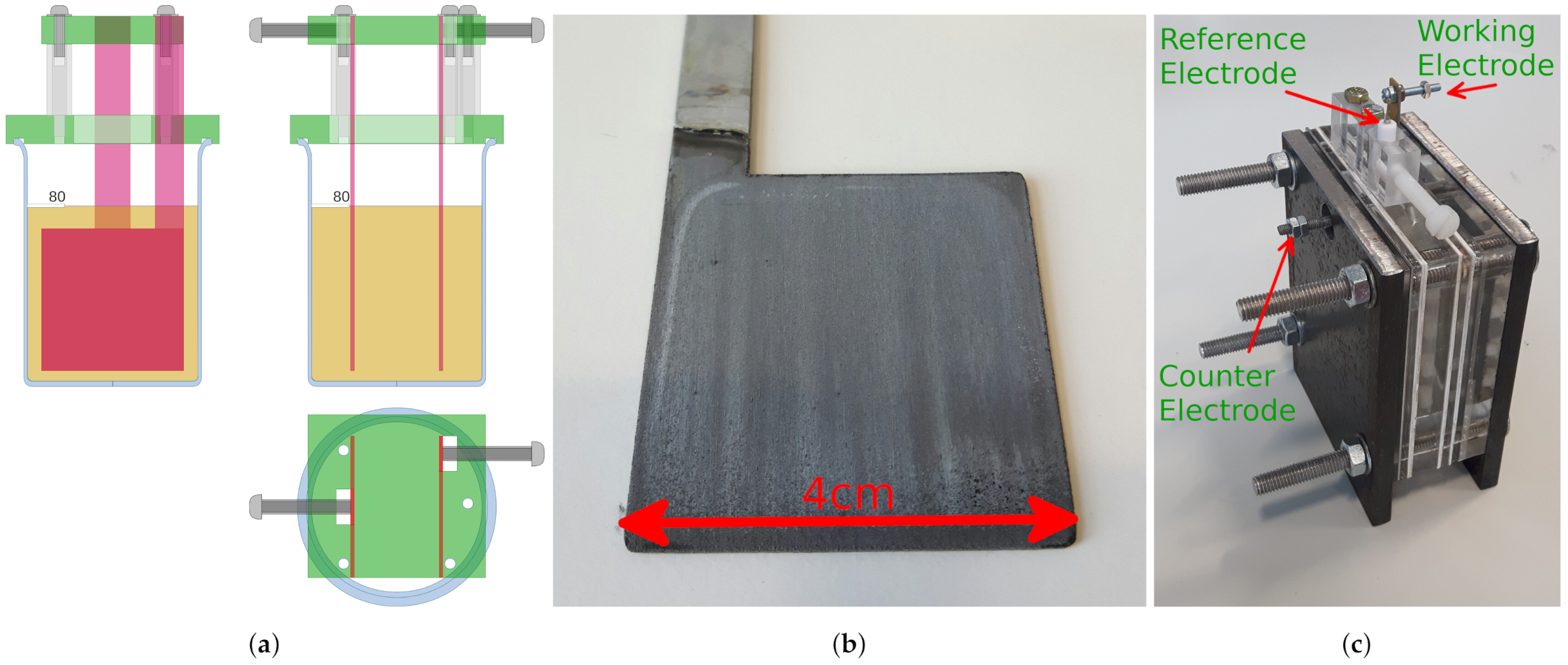
All procedures were conducted in standard laboratory 100 mL beakers. Such beakers are large enough to accommodate up to two paddle-shaped 316-grade stainless-steel (316SS) electrodes, as shown in Figure 1a. All chemicals were standard reagent grade. For Raney1 the counter-electrode was made from a graphite rod. For Raney2 the counter-electrode was made from 316SS, which was partially consumed during the deposition, thereby progressively altering the composition of the coating. The typical appearance of the Raney2 coating, and the three-electrode cell into which it was assembled, were as shown in Figure 1b.
Electrodeposition: The 4 cm × 4 cm 316SS electrode was degreased in hot 25 wt% NaOH for 1 min, then submerged in 18 wt% HCl for 1 min at room temperature, before being placed in 70 wt% H2SO4 for 3 min at an anodic current of 108 mA m−2. The electrode was then placed in a nickel strike solution consisting of 240 g L−1 NiCl2·6H2O and 120 mL L−1 HCl for 5 min at a cathodic current of mA cm−2. Between each step the electrode was rinsed with deionised water, and the air-exposure time minimised. At this point the electrode was covered in a thin, adherent coating of nickel that was able to act as a base for any subsequent functional coating [20]. The electrode was then immersed in a modified Watt’s Bath consisting of 330 g L−1 NiSO4·6H2O, 45 g L−1 NiCl2·6H2O, 37 g L−1 H3BO3 and 20 g L−1 ZnCl2 at 50 for 60 min at a cathodic current of mA cm−2. Lastly the coating was activated by immersion in 6 NaOH at 50 for 48 h.
Potentiostat: All electrochemical experiments were performed on an Ivium n-Stat potentiostat. The electrolyte was NaOH, and the reference electrode was a commercial Ag/AgCl device containing 3 KCl, which was routinely calibrated against a standard calomel electrode. CV was performed within a 100 range around OCP at rates of 10 −1 or less. The potential was held for 10 s between changes of direction to allow diffusion gradients within the electrolyte to disperse. EIS was performed at frequencies below 10 around OCP, starting at low frequency. Method: impedance; technique: constant E; amplitude: between 10 and 100. The electrode was pretreated for 120 s at OCP to reduce initial transient currents. All EIS results were analysed within the IviumSoft software package, wherein RCR and RQ equivalent circuits were fitted to the results (where Q is the symbol that represents a CPE).
Equivalent Capacitance: According to Brug et al. the double-layer capacitance for the series connection of a resistor and a constant-phase element can be calculated using:
where , and n are the best-fit parameters of an RQ network to either the EIS or CV results [38,39]. It is worth noting that in the Brug paper is referred to as , and n is referred to as . can be expressed in units of −1 and in , or as an area pseudo-capacitance Ω−1 cm−2 in which case must be in . From this the roughness factor can be calculated using:
where is the capacitance of a completely smooth surface, which is known to be 40 −2 in alkaline conditions [40].
RQ Transient Best-fit: As a function of time, the voltage across a CPE is given by a convolution integral:
where is the magnitude of the CPE (or its ‘pseudo-capacitance’), n is the phase of the CPE, and is the gamma function [41]. For cyclic voltammetry, where it is the voltage that is controlled and the current that is measured, solving this involves expressing the electrical network as a differential equation.
For example, for the basic RC network shown in Figure 2 the equation can be expressed as:
where q is electrical charge, such that , and is equal to the voltage on the capacitor . The Euler method can be used to approximate a solution to this equation, based on the first-order simplification that:
where h is the step size in time. Replacing the capacitor by a CPE, and therefore by , produces:
This iterative scheme can be converted into a computer program, permitting the simulation of the response of the network to any arbitrary voltage waveform (see SI of Reference [42]).
If the values R, and n are taken to be the axes of a three-dimensional solution space, then standard gradient descent techniques can be employed to find the position of the best-fit, i.e., the position that minimises a suitable cost-function, for example one defined as the square of the difference between the measured and simulated waveforms.
3. Results
3.1. Raney1
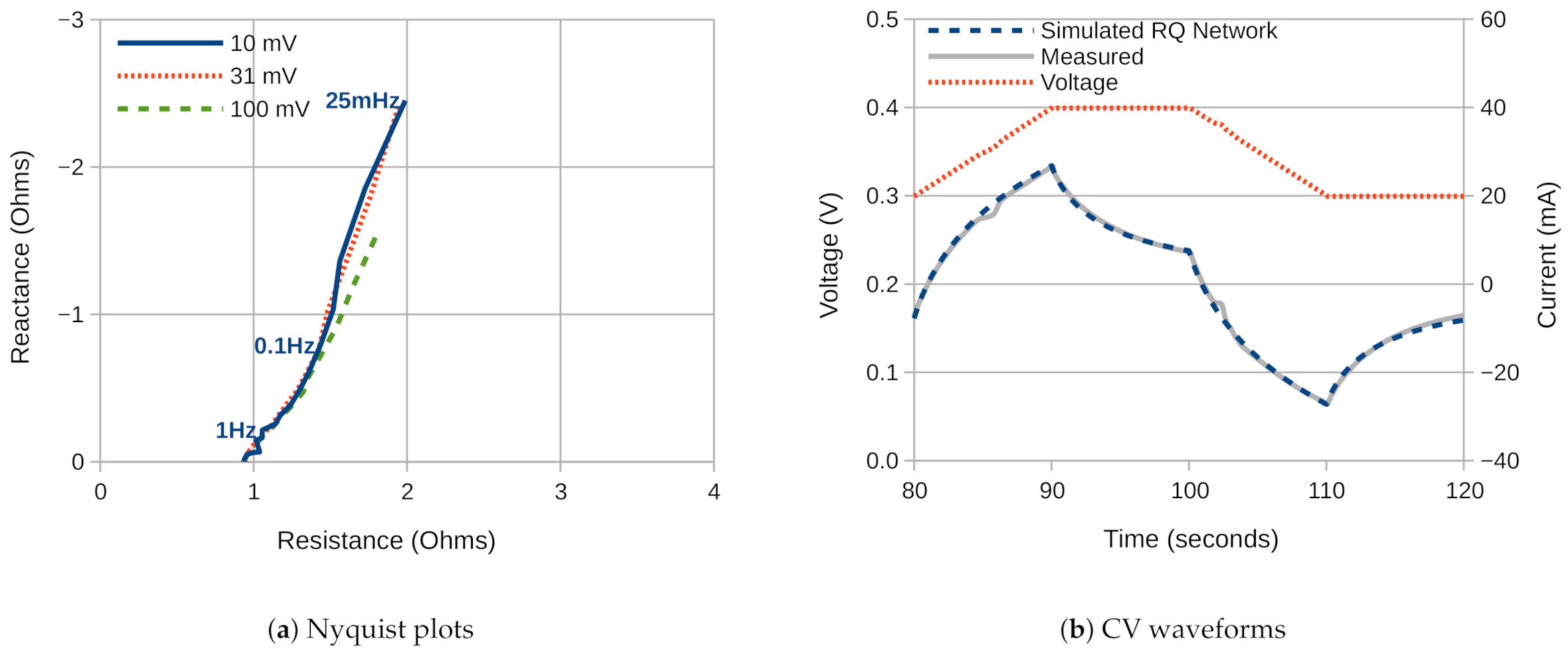
The Raney1 coating is deposited using a graphite counter electrode, which does not dissolve, and therefore does not alter the make-up of the coating. It therefore constitutes the standard Raney nickel coating. The typical EIS results for a Raney1 nickel coated 316SS electrode were as shown in Figure 3a. The Figure shows Nyquist plots taken at 3 different values of signal amplitude. Consistent results were produced until the signal amplitude reached about 100 . Above this amplitude the course of the plot deviated, which suggests that the electrochemical system was being taken out of its linear zone.
In all of the traces, the double-layer capacitance of the electrode produced constant-phase behaviour below approximately 1 , in series with a constant ohmic resistance of , which for an electrode with an exposed area of 3 cm × 3 cm equates to . The proposed electrical equivalent circuit was therefore a series RQ network, with the best-fit parameters generated by Iviumsoft as presented in the top three rows of Table 1.
The table includes an equivalent capacitance, calculated using Equation (3), which shows that the corresponding double-layer capacitance was about 166 −2, which equates to a roughness factor of 4150. The higher value of 255 −2 was measured at the highest EIS amplitude, and should be treated with caution.
The CV waveform for the same electrode measured at 10 −1 was as presented in Figure 3b. The figure shows that the double-layer capacitance was too high to achieve a stable current value within the time frame available, which made it difficult to extract a straightforward value for the capacitance. As discussed in a previous published work, although it is tempting to fit an RC network to the waveform, it does not have the correct shape. This is because, as is seen for electrodes with lower capacitance, the waveform asymptotes towards a slope. Neither is it possible to fit an RCR network to the waveform, since this produces a misleadingly high value for the capacitance. This is a result of the constant-phase behaviour of the double-layer capacitance, which not only produces the asymptotic slope, but also alters the curvature of the waveform so that it appears to have a larger time-constant [42].
Therefore the waveform was fitted to an RQ network using the RQ Transient Best-fit method, with the simulation of that network as shown by the dashed blue line in Figure 3b. The best-fit parameters for this network are as shown in the bottom row of Table 1, and produce a convincing match to the measured waveform. To the knowledge of the author, this is the first time that such a technique has been presented in the literature. The CV results therefore suggest a value for the double-layer capacitance of 266 −2, which equates to a roughness factor of 6650. Some possible explanations for the disparity between the capacitance suggested by EIS and CV will be discussed later.
3.2. Raney2
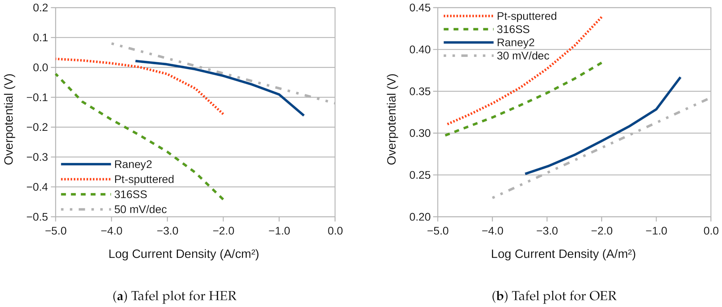
The Raney2 coating was deposited using a 316-grade stainless-steel counter electrode, which partially dissolved during the deposition, and therefore progressively altered the make-up of the coating. It therefore constitutes a version of the coating which has been chemically and morphologically altered by the dissolving stainless-steel [37]. The electrical performance of the Raney2 coating for hydrogen and oxygen evolution was as shown in Figure 4, with the resultant Tafel slopes and overpotentials at 10 −2 as presented in Table 2. The electrode had previously been aged by hydrogen evolution at −2 for 42 h.
The figures show that the performance of the uncoated 316SS for hydrogen evolution was poor, with an overpotential at 10 −2 of nearly . Sputter coating with Pt reduced this overpotential by nearly , which is to be expected since Pt is an excellent hydrogen evolution catalyst. However, with its higher surface area, the Raney2 coating was able to outperform the Pt-coated electrode, achieving a remarkably low overpotential of just 28 at the most widely reported benchmark figure of 10 −2. In fact, the overpotential was still below 100 at 100 −2.
For oxygen evolution, the uncoated 316SS performed well, as has been previously reported [37,43]. It even outperformed the Pt-coated electrode, which underlines how specific Pt is to hydrogen evolution, and why it is not generally used as an OER catalyst [40,44]. In addition, Pt is unstable, and known to dissolve under conditions of alkaline OER [45]. With the Raney2 coating, the overpotential was reduced by , which equates to an increase in current density of more than three orders of magnitude.
It should be noted that these current densities are reported relative to the geometric surface area of the electrode, which places the Pt electrode at a considerable disadvantage. This is fair, because it is much more scalable to generate high area nickel than high area platinum. In fact, it is anticipated that the activity of the Raney2 coating relative to its electrochemical surface area is little different to that of the uncoated electrode, simply because they are both comprised chiefly of nickel and iron. From the horizontal shifts in Figure 4a it can therefore be surmised that Pt is approximately 102.5 times more active for HER than 316SS given equal surface areas. However, the Raney2 coating presents approximately 104 more effective surface area for HER, and 103 for OER, which affords it greater performance.
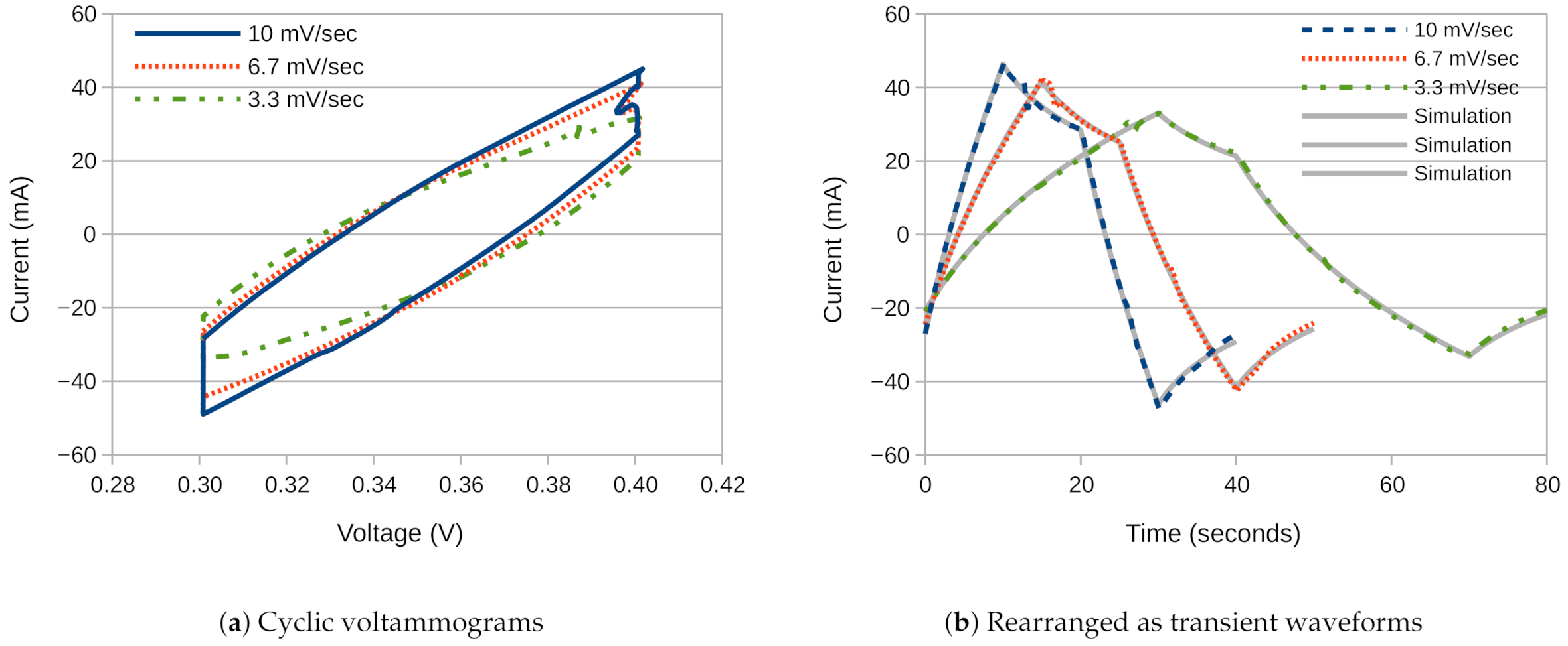
To further assess the surface area of the Raney2 coating, cyclic voltammograms were recorded for three different voltage sweep rates around OCP, as shown in Figure 5a. These show that the coating has a very high level of capacitance, and the waveforms did not come close to achieving a steady value within the 100 window.
Therefore, the voltammograms were rearranged as waveform segments, as shown in Figure 5b. These segments were then suitable for use with the RQ Transient Best-fit method, which produced the results presented in Table 3. To aid comparison, the transient simulation results of the three RQ networks have been underlaid under the measurement data in Figure 5b, and produce a convincing level of agreement.
The results in Table 1 and Table 3 show a consistent pattern, that being that the reported capacitance was greatest when the electrode was driven at the greatest EIS amplitude, or the fastest CV ramp-rate. The reason for this is not known, but it is perhaps significant that for CV the CPE phase-angle n fell to 0.67 at the fastest ramp-rate, and likewise for EIS the phase-angle fell to 0.60 at the largest amplitude. This is not within the normal valid range for the phase angle of a CPE, which is typically between 0.7 and 1.0. Instead, it is closer to the value of 0.5 that would be expected of a Warburg diffusion element. This may be an indication that the large electrode surface area and large amplitude or ramp-rate are impinging upon the mass-transportation limits of the electrolyte. Alternatively, it could be a sign that the assumptions on which Equation (3) is based were no longer valid. According to Brug et al. these assumptions are based on the observation of similar constant-phase behaviour in dielectric materials.
Given this pattern of results, it would therefore appear that the most accurate value for the roughness factor for Raney2 from Table 3 is that for the slowest ramp-rate, i.e., 42,490. This is many times larger than the figure of up to 1700 that was obtained by Marozzi et al. [15], the value of 3620 obtained by Ganesh et al. [46], and the figure of 4400 obtained by Suffredini et al. [47], all for electrodeposited forms of nickel onto metallic sheet. It is also larger than that measured for Raney nickel by Herraiz-Cardona et al., which was about 28,000 at zero HER over-potential [21].
EIS results for the same electrode confirm that the series resistance between WE and RE was 2, which is close to the figure of 2 produced by RQ Transient Best-fit, and builds confidence that this method is able to perform accurate measurements. Similarly, the value for the phase argument n of 0.70 is close to the value of 0.68 measured by EIS in Table 1 for a closely related coating. The average of the capacitance measurements was −2, which equates to a roughness factor of 47,150, and helps to explain how the coating generated such impressively low overpotential figures. However, the value for the capacitance could not be confirmed by EIS, because the frequency range did not go low enough to reveal the point where the impedance magnitude increased. Nevertheless, in combination with Table 1, the CV measurement provides good evidence of the electrode’s high surface area.
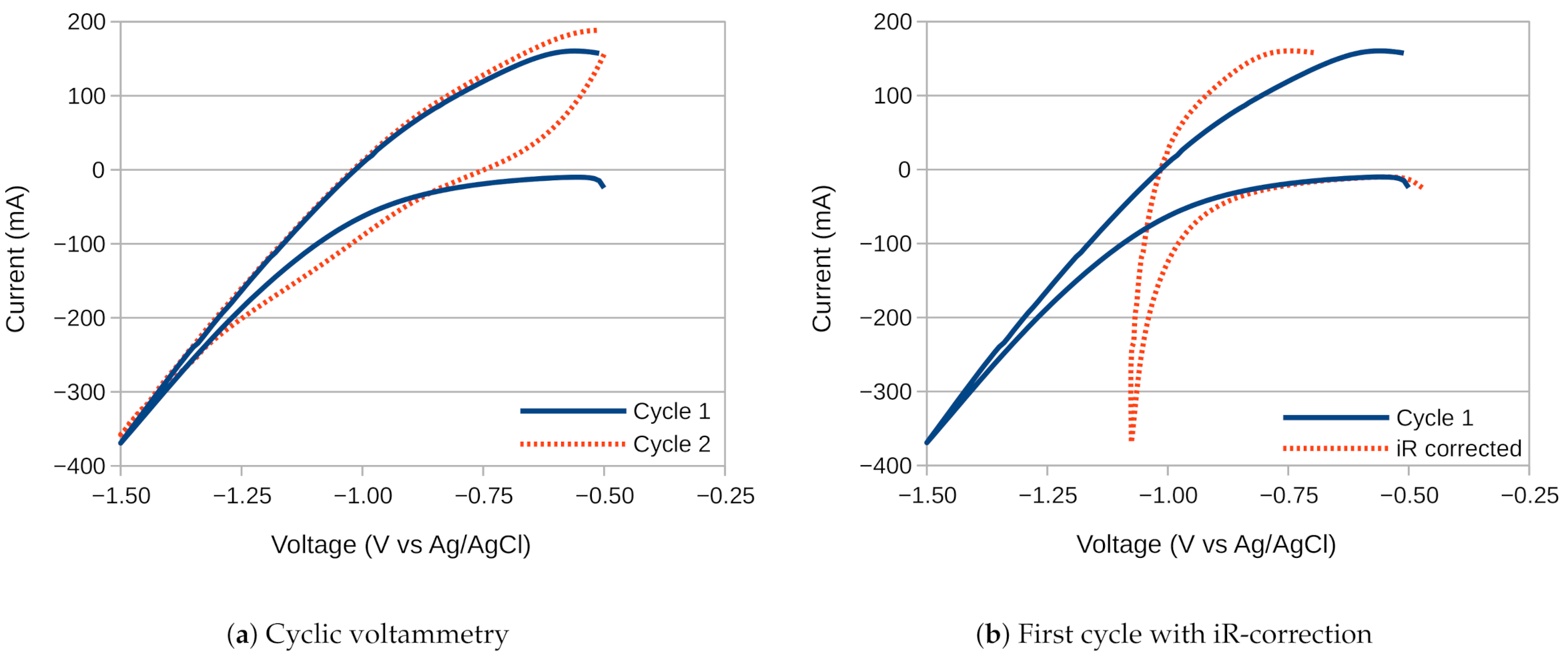
To further evaluate this high capacitance, a freshly deposited Raney2-coated electrode was investigated using cyclic-voltammetry over a wide voltage range, with the results as presented in Figure 6.
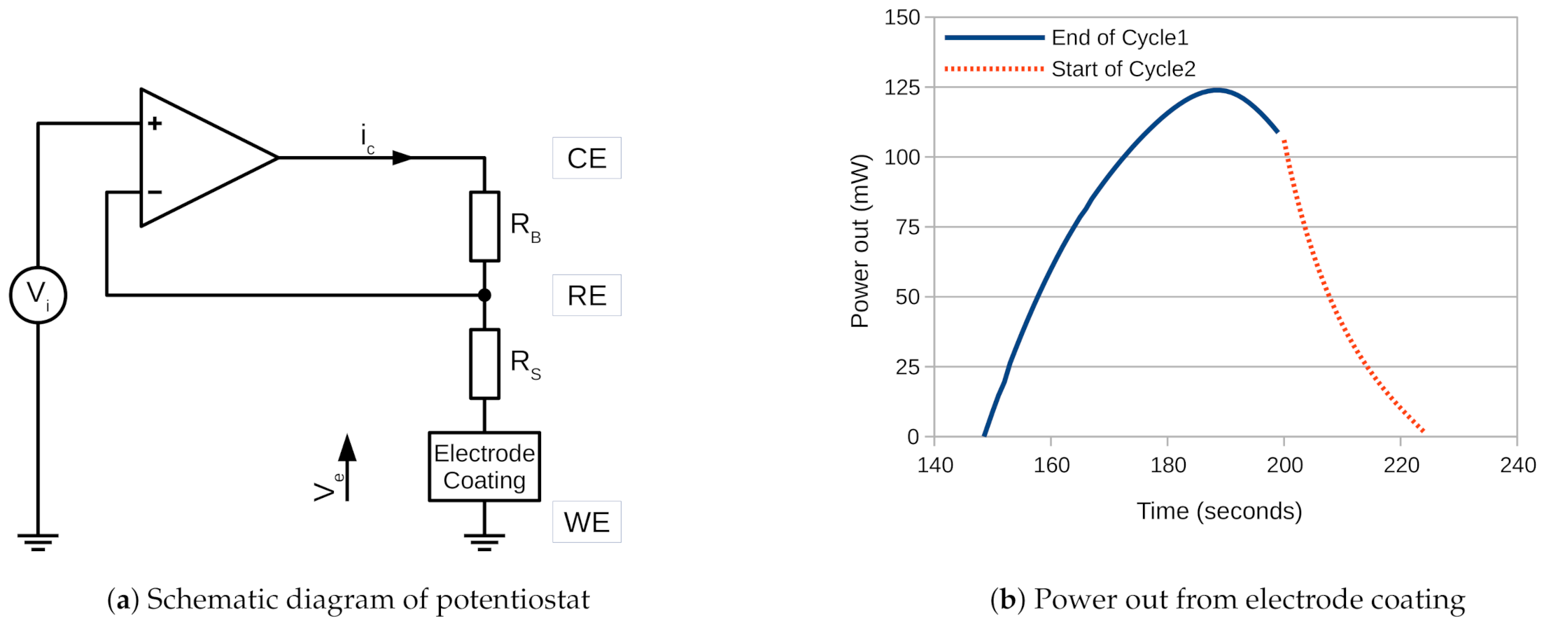
The figure shows that on the cathodic sweep of cycle 1 the current remained negative, and below the electrode was evolving hydrogen. However, on the anodic sweep the current went positive at , which means that the electrode was supplying electrical power. This continued until the voltage reached on cycle 2. Since power is equal to current times voltage, it is possible to calculate the total electrical power supplied by the electrode between these two points. However, the voltage must be corrected for iR losses, as shown in Figure 6b, for which it is helpful to refer to the schematic diagram shown in Figure 7a.
The potentiostat is represented by an amplifier, which continually alters the voltage of CE until the difference between RE and WE is equal to the desired input voltage . No current passes into the negative input of the amplifier since it is high impedance.
The ohmic resistance of the electrolyte solution and electrical wiring, , between RE and WE is known from EIS, based on the valid assumption that the electrode coating is a short-circuit at high-frequency. Regardless of the sign of , this permits to be calculated as:
which is the equation for standard iR correction. Note that if is of opposite polarity to , then will be larger than . If at any time and are of opposite polarity, this means that the electrode coating is supplying electrical power, and the total energy out can be calculated by integrating the product of the two:
which is equivalent to measuring the area under the curve in Figure 7b. When this is done, the figure for the amount of energy released after one cycle is , which means that the Raney2 coating was able to store and release −2 in the form of hydride in a comparatively short period of time. Note that it is not possible to determine the ratio between energy stored and released, because some of the energy was used to split water.
4. Comparisons
Hydrogen evolution: A limited survey of recently published results for earth-abundant hydrogen evolution catalysts is as presented in Table 4. (Abbreviations: CC: carbon cloth; CCH: cobaltous carbonate hydroxide; CFP: carbon fibre paper; CNT: carbon nanotubes; DO: derived oxide; FTO: fluorine-doped tin oxide; GCE: glassy carbon electrode; LDH: layered double hydroxide; MNA: mesoporous nanorod array; MS: microsphere; NA: nanorod array; NF: nickel foam; NP: nanoplates; NR: nanorods; NrGO: nitrogenated reduced graphene oxide; NSh: nanosheets; Nst: nanostructures; NA: nanowire arrays). The table shows that the overpotential, at least at 10 −2, can be almost arbitrarily small. As a result, some authors only quote the overpotential at 100 −2, by which point hydrogen evolution is very well established. Therefore, the table has been generated by taking measurements from published diagrams, so as to establish a common baseline. Many papers also cite a well-known commercial catalyst called ‘PtC’ (platinum on carbon) as a baseline for comparison, therefore it has been included in the table, even though it is not earth-abundant. It is heartening to note that many of the catalysts are able to outperform it, including the Raney2 catalyst studied in this paper.
Oxygen evolution: A limited survey of recently published results for earth-abundant oxygen evolution catalysts is as presented in Table 5.
Although it can be difficult to make direct comparisons between catalysts, a picture has been emerging over recent years of the limits to which transition metals can be taken. At present this looks to be an overpotential of about 200 at a current density of 10 −2. This current density is chosen because it is the most widely quoted figure, and because it is described as the most significant for solar fuel synthesis [40]. However, it is not the most significant figure for a commercial electrolyser, which benefits from attaining figures about two orders of magnitude higher. As an illustration of what is possible, figures of 690 −2 at an overpotential of 281 are quoted for the FeP/Ni2P catalyst, whereas the NiFe-N catalyst has achieved 360 −2 at an overpotential of 255 , fully 220 less than the equivalent figure measured for IrO2.
The table shows that the Raney2 catalyst is certainly not exceptional, being about 100 behind the leading edge. However, it is unusual in being one of only two bifunctional catalysts listed in the table. It should also be noted that the developers of the leading catalyst, FeCoW, discovered that any annealing of their catalyst had a destructive effect on its catalytic ability. This they ascribed to the phase separation of the ternary catalyst into discrete crystalline particles of Fe3O4, Co3O4 and CoWO4. This therefore highlights the difficulty of producing highly active catalysts that are not subsequently prone to some form of instability.
As a bifunctional catalyst the Raney2 coating is not just highly stable, but also achieves a combined overpotential of just 320 at 10 −2. In addition, since 10 of the higher-performing catalysts in Table 5 feature nickel or nickel-iron, the scope for increasing its specificity for OER appears promising.
5. Conclusions
This paper presents a new technique for the fitting of a resistor/constant-phase-element network to cyclic voltammetry (CV) waveforms recorded at open-circuit potential. From this a figure for the double-layer capacitance can be calculated, in accordance with Equation (3). The agreement between simulation and measurement is convincingly close, as shown in Figure 3b and Figure 5b. As such the technique may help with the interpretation of CV results, especially ones involving very high capacitance where alternative techniques become problematic. In addition, there is no reason the technique cannot be extended to the fitting of an RQR network, including a charge transfer resistance, to waveforms recorded away from OCP.
This fitting technique permitted a value to be measured for the roughness factor of 42,500, which is larger than any comparable figures so far discovered in the literature. The coating also demonstrated potentially useful levels of performance as a supercapacitor material, where it attained a capacitance of −2, and as a hydride storage material, where it stored −2. However, possibly its greatest utility is as an electrocatalyst for water-splitting, both for hydrogen and oxygen evolution, where it achieved a combined overpotential of just 320 at the most widely reported benchmark figure of 10 −2. This equates to a water-splitting voltage of just , and is just 70 above the thermoneutral voltage. Taking into consideration the simplicity of the deposition procedure, we believe this makes Raney2 the highest performing simple bifunctional electrocatalytic coating known.
Author Contributions
Conceptualization, C.W.D.; methodology, W.J.F.G.; software, W.J.F.G.; formal analysis, W.J.F.G.; investigation, W.J.F.G.; supervision, C.W.D.; funding acquisition, C.W.D. All authors have read and agreed to the published version of the manuscript.
Funding
This research received no external funding.
Institutional Review Board Statement
Not applicable.
Informed Consent Statement
Not applicable.
Data Availability Statement
The data presented in this study are openly available in FigShare at doi.org/10.6084/m9.figshare.13498692.
Acknowledgments
W.J.F.G. was funded by a College of Engineering Zienkiewicz PhD Scholarship from Swansea University, UK.
Conflicts of Interest
The authors declare no conflict of interest.
Abbreviations
The following abbreviations are used in this manuscript:
| 316SS | 316-grade Stainless Steel |
| CE | Counter Electrode |
| CPE | Constant Phase Element |
| CV | Cyclic Voltammetry |
| EIS | Electrochemical Impedance Spectroscopy |
| HER | Hydrogen Evolution Reaction |
| ICT | Information and Communications Technology |
| OCP | Open-Circuit Potential |
| OER | Oxygen Evolution Reaction |
| PEM | Proton Exchange Membrane |
| RC | a Resistor–Capacitor network |
| RCR | a Resistor–Capacitor–Resistor network |
| RE | Reference Electrode |
| RQ | a Resistor–CPE(Q) network |
| SI | Supplementary Information |
| WE | Working Electrode |
References
- Jones, N. The Information Factories. Nat. Mag. 2018, 561, 163–166. [Google Scholar] [CrossRef] [PubMed]
- Andrae, A.; Edler, T. On Global Electricity Usage of Communication Technology: Trends to 2030. Challenges 2015, 6, 117–157. [Google Scholar] [CrossRef] [Green Version]
- Gannon, W.J.; Jones, D.R.; Dunnill, C.W. Enhanced Lifetime Cathode for Alkaline Electrolysis Using Standard Commercial Titanium Nitride Coatings. Processes 2019, 7, 112. [Google Scholar] [CrossRef] [Green Version]
- Jones, D.; Phillips, R.; Gannon, W.J.; Rome, B.; Warwick, M.; Dunnill, C. Photocapacitive CdS/WOx nanostructures for solar energy storage. Sci. Rep. 2019, 9. [Google Scholar] [CrossRef] [PubMed] [Green Version]
- Gannon, W.J.; Warwick, M.E.A.; Dunnill, C.W. Woven Stainless-Steel Mesh as a Gas Separation Membrane for Alkaline Water-Splitting Electrolysis. Membranes 2020, 10, 109. [Google Scholar] [CrossRef]
- Yu, F.; Yu, L.; Mishra, I.K.; Yu, Y.; Ren, Z.F.; Zhou, H.Q. Recent developments in earth-abundant and non-noble electrocatalysts for water electrolysis. Mater. Today Phys. 2018, 7, 121–138. [Google Scholar] [CrossRef]
- Medford, A.J.; Vojvodic, A.; Hummelshøj, J.S.; Voss, J.; Abild-Pedersen, F.; Studt, F.; Bligaard, T.; Nilsson, A.; Nørskov, J.K. From the Sabatier principle to a predictive theory of transition-metal heterogeneous catalysis. J. Catal. 2015, 328, 36–42. [Google Scholar] [CrossRef] [Green Version]
- Eftekhari, A. Electrocatalysts for hydrogen evolution reaction. Int. J. Hydrogen Energy 2017, 42, 11053–11077. [Google Scholar] [CrossRef]
- Nørskov, J.K.; Bligaard, T.; Logadottir, A.; Kitchin, J.R.; Chen, J.G.; Pandelov, S.; Stimming, U. Trends in the Exchange Current for Hydrogen Evolution. J. Electrochem. Soc. 2005, 152, J23. [Google Scholar] [CrossRef] [Green Version]
- Smith, A.J.; Trimm, D.L. The Preparation of Skeletal Catalysts. Annu. Rev. Mater. Res. 2005, 35, 127–142. [Google Scholar] [CrossRef]
- Schiller, G.; Henne, R.; Mohr, P.; Peinecke, V. High Performance Electrodes for an Advanced Intermittently Operated 10-kW Alkaline Water Electrolyzer. Int. J. Hydrogen Energy 1998, 23, 761–765. [Google Scholar] [CrossRef]
- Endoh, E.; Otouma, H.; Morimoto, T.; Oda, Y. New Raney nickel composite-coated electrode for hydrogen evolution. Int. J. Hydrogen Energy 1987, 12, 473–479. [Google Scholar] [CrossRef]
- Balej, J.; Divisek, J.; Schmitz, H.; Mergel, J. Preparation and properties of raney nickel electrodes on Ni-Zn base for H2 and O2 evolution from alkaline solutions Part I: Electrodeposition of Ni-Zn alloys from chloride solutions. J. Appl. Electrochem. 1992, 22, 705–710. [Google Scholar] [CrossRef]
- De Giz, M.J.; Machado, S.A.S.; Avaca, L.A.; Gonzalez, E.R. High area Ni-Zn and Ni-Co-Zn codeposits as hydrogen electrodes in alkaline solutions. J. Appl. Electrochem. 1992, 22, 973–977. [Google Scholar] [CrossRef]
- Marozzi, C.A.; Chialvo, A.C. Development of electrode morphologies of interest in electrocatalysis. Part 1: Electrodeposited porous nickel electrodes. Electrochim. Acta 2000, 45, 2111–2120. [Google Scholar] [CrossRef]
- Birry, L.; Lasia, A. Studies of the hydrogen evolution reaction on Raney nickel–molybdenum electrodes. J. Appl. Electrochem. 2004, 34, 735–749. [Google Scholar] [CrossRef]
- Chade, D.; Berlouis, L.; Infield, D.; Cruden, A.; Nielsen, P.T.; Mathiesen, T. Evaluation of Raney nickel electrodes prepared by atmospheric plasma spraying for alkaline water electrolysers. Int. J. Hydrogen Energy 2013, 38, 14380–14390. [Google Scholar] [CrossRef]
- Divisek, J.; Malinowski, P.; Mergel, J.; Schmitz, H. Improved components for advanced alkaline water electrolysis. Int. J. Hydrogen Energy 1988, 13, 141–150. [Google Scholar] [CrossRef]
- Sheela, G.; Pushpavanam, M.; Pushpavanam, S. Zinc-nickel alloy electrodeposits for water electrolysis. Int. J. Hydrogen Energy 2002, 27, 627–633. [Google Scholar] [CrossRef]
- Herraiz-Cardona, I.; Ortega, E.; Vázquez-Gómez, L.; Pérez-Herranz, V. Electrochemical characterization of a NiCo/Zn cathode for hydrogen generation. Int. J. Hydrogen Energy 2011, 36, 11578–11587. [Google Scholar] [CrossRef]
- Herraiz-Cardona, I.; Ortega, E.; Pérez-Herranz, V. Impedance study of hydrogen evolution on Ni/Zn and Ni-Co/Zn stainless steel based electrodeposits. Electrochim. Acta 2011, 56, 1308–1315. [Google Scholar] [CrossRef]
- Herraiz-Cardona, I.; González-Buch, C.; Valero-Vidal, C.; Ortega, E.; Pérez-Herranz, V. Co-modification of Ni-based type Raney electrodeposits for hydrogen evolution reaction in alkaline media. J. Power Sources 2013, 240, 698–704. [Google Scholar] [CrossRef]
- González-Buch, C.; Herraiz-Cardona, I.; Ortega, E.; García-Antón, J.; Pérez-Herranz, V. Synthesis and characterization of macroporous Ni, Co and Ni-Co electrocatalytic deposits for hydrogen evolution reaction in alkaline media. Int. J. Hydrogen Energy 2013, 38, 10157–10169. [Google Scholar] [CrossRef]
- Solmaz, R.; Döner, A.; Kardaş, G. Preparation, characterization and application of alkaline leached CuNiZn ternary coatings for long-term electrolysis in alkaline solution. Int. J. Hydrogen Energy 2010, 35, 10045–10049. [Google Scholar] [CrossRef]
- Solmaz, R. Electrochemical preparation, characterization, and application of a novel cathode material, mild Steel/Ni/NiZn-Pt, for alkaline water electrolysis. Energy Sources Part A Recover. Util. Environ. Eff. 2014, 36, 1212–1218. [Google Scholar] [CrossRef]
- Solmaz, R.; Döner, A.; Doğrubaş, M.; Erdoğan, I.Y.; Kardaş, G. Enhancement of electrochemical activity of Raney-type NiZn coatings by modifying with PtRu binary deposits: Application for alkaline water electrolysis. Int. J. Hydrogen Energy 2016, 41, 1432–1440. [Google Scholar] [CrossRef]
- Solmaz, R.; Salcı, A.; Yüksel, H.; Doğrubaş, M.; Kardaş, G. Preparation and characterization of Pd-modified Raney-type NiZn coatings and their application for alkaline water electrolysis. Int. J. Hydrogen Energy 2017, 42, 2464–2475. [Google Scholar] [CrossRef]
- Solmaz, R. Gold-supported activated NiZn coatings: Hydrogen evolution and corrosion studies. Int. J. Energy Res. 2017, 41, 1452–1459. [Google Scholar] [CrossRef]
- Balej, J. Electrocatalysts for oxygen evolution in advanced water electrolysis. Int. J. Hydrogen Energy 1985, 10, 89–99. [Google Scholar] [CrossRef]
- Bates, M.K.; Jia, Q.; Doan, H.; Liang, W.; Mukerjee, S. Charge-Transfer Effects in Ni-Fe and Ni-Fe-Co Mixed-Metal Oxides for the Alkaline Oxygen Evolution Reaction. ACS Catal. 2016, 6, 155–161. [Google Scholar] [CrossRef]
- Tsay, P.; Hu, C.C. Non-Anomalous Codeposition of Iron-Nickel Alloys Using Pulse-Reverse Electroplating Through Means of Experimental Strategies. J. Electrochem. Soc. 2002, 149, C492. [Google Scholar] [CrossRef]
- Tozar, A.; Karahan, I.H. Structural and corrosion protection properties of electrochemically deposited nano-sized Zn-Ni alloy coatings. Appl. Surf. Sci. 2014, 318, 15–23. [Google Scholar] [CrossRef]
- Soares, D.M. Hydride Effect on the Kinetics of the Hydrogen Evolution Reaction on Nickel Cathodes in Alkaline Media. J. Electrochem. Soc. 1992, 139, 98. [Google Scholar] [CrossRef] [Green Version]
- Olivares-Ramírez, J.M.; Campos-Cornelio, M.L.; Godínez, J.U.; Borja-Arco, E.; Castellanos, R.H. Studies on the hydrogen evolution reaction on different stainless steels. Int. J. Hydrogen Energy 2007, 32, 3170–3173. [Google Scholar] [CrossRef]
- Sapountzi, F.M.; Gracia, J.M.; Weststrate, C.K.J.; Fredriksson, H.O.; Niemantsverdriet, J.H. Electrocatalysts for the generation of hydrogen, oxygen and synthesis gas. Prog. Energy Combust. Sci. 2017, 58, 1–35. [Google Scholar] [CrossRef] [Green Version]
- Divisek, J.; Schmitz, H.; Steffen, B. Electrocatalyst Materials Evolution for Hydrogen. Electrochim. Acta 1994, 39, 1723–1731. [Google Scholar] [CrossRef]
- Gannon, W.J.; Dunnill, C.W. Raney Nickel 2.0: Development of a high-performance bifunctional electrocatalyst. Electrochim. Acta 2019, 322, 134687. [Google Scholar] [CrossRef]
- Brug, G.J.; van den Eeden, A.L.G.; Sluyters-Rehbach, M.; Sluyters, J.H. The analysis of electrode impedances complicated by the presence of a constant phase element. J. Electroanal. Chem. 1984, 176, 275–295. [Google Scholar] [CrossRef]
- Jovic, V. Determination of the Correct Value of Cdl From the Impedance Results Fitted by the Commercially Available Software. Technical Report; University of Belgrade: Belgrade, Serbia, 2003. [Google Scholar]
- McCrory, C.C.L.; Jung, S.; Ferrer, I.M.; Chatman, S.M.; Peters, J.C.; Jaramillo, T.F. Benchmarking Hydrogen Evolving Reaction and Oxygen Evolving Reaction Electrocatalysts for Solar Water Splitting Devices. J. Am. Chem. Soc. 2015, 137, 4347–4357. [Google Scholar] [CrossRef] [Green Version]
- Athanasiou, V.; Konkoli, Z. On the efficient simulation of electrical circuits with constant phase elements: The Warburg element as a test case. Int. J. Circuit Theory Appl. 2018, 46, 1072–1090. [Google Scholar] [CrossRef]
- Gannon, W.J.; Dunnill, C.W. Apparent disagreement between cyclic voltammetry and electrochemical impedance spectroscopy explained by time-domain simulation of constant phase elements. Int. J. Hydrogen Energy 2020, 45, 22383–22393. [Google Scholar] [CrossRef]
- Colli, A.N.; Girault, H.H.; Battistel, A. Non-precious electrodes for practical alkaline water electrolysis. Materials 2019, 12, 1336. [Google Scholar] [CrossRef] [Green Version]
- McCrory, C.C.L.; Jung, S.; Peters, J.C.; Jaramillo, T.F. Benchmarking heterogeneous electrocatalysts for the oxygen evolution reaction. J. Am. Chem. Soc. 2013, 135, 16977–16987. [Google Scholar] [CrossRef] [PubMed]
- Bagotzky, V.S.; Khrushcheva, E.I.; Tarasevich, M.R.; Shumilova, N.A. Corrosion of platinum catalyst in alkaline solutions. J. Power Sources 1982, 8, 301–309. [Google Scholar] [CrossRef]
- Ganesh, V.; Lakshminarayanan, V. Preparation of high surface area nickel electrodeposit using a liquid crystal template technique. Electrochim. Acta 2004, 49, 3561–3572. [Google Scholar] [CrossRef]
- Suffredini, H.B.; Cerne, J.L.; Crnkovic, F.C.; MacHado, S.A.S.; Avaca, L.A. Recent developments in electrode materials for water electrolysis. Int. J. Hydrogen Energy 2000, 25, 415–423. [Google Scholar] [CrossRef]
- Wang, M.; Wang, Z.; Yu, X.; Guo, Z. Facile one-step electrodeposition preparation of porous NiMo film as electrocatalyst for hydrogen evolution reaction. Int. J. Hydrogen Energy 2015, 40, 2173–2181. [Google Scholar] [CrossRef]
- Wang, Y.; Zhang, G.; Xu, W.; Wan, P.; Lu, Z.; Li, Y.; Sun, X. A 3D Nanoporous Ni-Mo Electrocatalyst with Negligible Overpotential for Alkaline Hydrogen Evolution. ChemElectroChem 2014, 1, 1138–1144. [Google Scholar] [CrossRef]
- Song, F.; Li, W.; Yang, J.; Han, G.; Liao, P.; Sun, Y. Interfacing nickel nitride and nickel boosts both electrocatalytic hydrogen evolution and oxidation reactions. Nat. Commun. 2018, 9. [Google Scholar] [CrossRef] [Green Version]
- Panda, C.; Menezes, P.W.; Yao, S.; Schmidt, J.; Walter, C.; Hausmann, J.N.; Driess, M. Boosting Electrocatalytic Hydrogen Evolution Activity with a NiPt3@NiS Heteronanostructure Evolved from a Molecular Nickel-Platinum Precursor. J. Am. Chem. Soc. 2019, 141, 13306–13310. [Google Scholar] [CrossRef]
- Yu, F.; Zhou, H.; Huang, Y.; Sun, J.; Qin, F.; Bao, J.; Goddard, W.A.; Chen, S.; Ren, Z. High-performance bifunctional porous non-noble metal phosphide catalyst for overall water splitting. Nat. Commun. 2018, 9, 1–9. [Google Scholar] [CrossRef] [Green Version]
- Zhang, J.; Wang, T.; Liu, P.; Liao, Z.; Liu, S.; Zhuang, X.; Chen, M.; Zschech, E.; Feng, X. Efficient hydrogen production on MoNi 4 electrocatalysts with fast water dissociation kinetics. Nat. Commun. 2017, 8, 1–8. [Google Scholar] [CrossRef]
- Zhang, T.; Yang, K.; Wang, C.; Li, S.; Zhang, Q.; Chang, X.; Li, J.; Li, S.; Jia, S.; Wang, J.; et al. Nanometric Ni5P4 Clusters Nested on NiCo2O4 for Efficient Hydrogen Production via Alkaline Water Electrolysis. Adv. Energy Mater. 2018, 8, 2–7. [Google Scholar] [CrossRef]
- Men, Y.; Li, P.; Zhou, J.; Cheng, G.; Chen, S.; Luo, W. Tailoring the Electronic Structure of Co2P by N Doping for Boosting Hydrogen Evolution Reaction at All pH Values. ACS Catal. 2019, 9, 3744–3752. [Google Scholar] [CrossRef]
- Chen, W.; Mishra, I.K.; Qin, Z.; Yu, L.; Zhou, H.; Sun, J.; Zhang, F.; Chen, S.; Wenya, G.E.; Yu, Y.; et al. Nickel phosphide based hydrogen producing catalyst with low overpotential and stability at high current density. Electrochim. Acta 2019, 299, 756–761. [Google Scholar] [CrossRef]
- Herraiz-Cardona, I.; Ortega, E.; Vázquez-Gómez, L.; Pérez-Herranz, V. Double-template fabrication of three-dimensional porous nickel electrodes for hydrogen evolution reaction. Int. J. Hydrogen Energy 2012, 37, 2147–2156. [Google Scholar] [CrossRef]
- Huang, Y.; Sun, Y.; Zheng, X.; Aoki, T.; Pattengale, B.; Huang, J.; He, X.; Bian, W.; Younan, S.; Williams, N.; et al. Atomically engineering activation sites onto metallic 1T-MoS 2 catalysts for enhanced electrochemical hydrogen evolution. Nat. Commun. 2019, 10, 1–11. [Google Scholar] [CrossRef]
- Xiang, R.; Duan, Y.; Peng, L.; Wang, Y.; Tong, C.; Zhang, L.; Wei, Z. Three-dimensional Core@Shell Co@CoMoO4 nanowire arrays as efficient alkaline hydrogen evolution electro-catalysts. Appl. Catal. B: Environ. 2019, 246, 41–49. [Google Scholar] [CrossRef]
- Gao, M.Y.; Yang, C.; Zhang, Q.B.; Zeng, J.R.; Li, X.T.; Hua, Y.X.; Xu, C.Y.; Dong, P. Facile electrochemical preparation of self-supported porous Ni-Mo alloy microsphere films as efficient bifunctional electrocatalysts for water splitting. J. Mater. Chem. A 2017, 5, 5797–5805. [Google Scholar] [CrossRef]
- Liu, C.; Gong, T.; Zhang, J.; Zheng, X.; Mao, J.; Liu, H.; Li, Y.; Hao, Q. Engineering Ni2P-NiSe2 heterostructure interface for highly efficient alkaline hydrogen evolution. Appl. Catal. B Environ. 2020, 262. [Google Scholar] [CrossRef]
- Shi, Z.; Wang, Y.; Lin, H.; Zhang, H.; Shen, M.; Xie, S.; Zhang, Y.; Gao, Q.; Tang, Y. Porous nanoMoC@graphite shell derived from a MOFs-directed strategy: An efficient electrocatalyst for the hydrogen evolution reaction. J. Mater. Chem. A 2016, 4, 6006–6013. [Google Scholar] [CrossRef]
- Zhu, Y.; Chen, H.C.; Hsu, C.S.; Lin, T.S.; Chang, C.J.; Chang, S.C.; Tsai, L.D.; Chen, H.M. Operando unraveling of the structural and chemical stability of P-substituted CoSe 2 electrocatalysts toward hydrogen and oxygen evolution reactions in alkaline electrolyte. ACS Energy Lett. 2019, 4, 987–994. [Google Scholar] [CrossRef]
- Xing, Z.; Li, Q.; Wang, D.; Yang, X.; Sun, X. Self-supported nickel nitride as an efficient high-performance three-dimensional cathode for the alkaline hydrogen evolution reaction. Electrochim. Acta 2016, 191, 841–845. [Google Scholar] [CrossRef]
- Lai, F.; Feng, J.; Ye, X.; Zong, W.; He, G.; Miao, Y.E.; Han, X.; Ling, X.Y.; Parkin, I.P.; Pan, B.; et al. Energy level engineering in transition-metal doped spinel-structured nanosheets for efficient overall water splitting. J. Mater. Chem. A 2019, 7, 827–833. [Google Scholar] [CrossRef] [Green Version]
- Zhu, W.; Yue, X.; Zhang, W.; Yu, S.; Zhang, Y.; Wang, J.; Wang, J. Nickel sulfide microsphere film on Ni foam as an efficient bifunctional electrocatalyst for overall water splitting. Chem. Commun. 2016, 52, 1486–1489. [Google Scholar] [CrossRef] [PubMed]
- Haque, F.; Zavabeti, A.; Zhang, B.Y.; Datta, R.S.; Yin, Y.; Yi, Z.; Wang, Y.; Mahmood, N.; Pillai, N.; Syed, N.; et al. Ordered intracrystalline pores in planar molybdenum oxide for enhanced alkaline hydrogen evolution. J. Mater. Chem. A 2019, 7, 257–268. [Google Scholar] [CrossRef]
- Feng, Y.; Yu, X.Y.; Paik, U. Nickel cobalt phosphides quasi-hollow nanocubes as an efficient electrocatalyst for hydrogen evolution in alkaline solution. Chem. Commun. 2016, 52, 1633–1636. [Google Scholar] [CrossRef]
- Liang, H.W.; Brüller, S.; Dong, R.; Zhang, J.; Feng, X.; Müllen, K. Molecular metal-Nx centres in porous carbon for electrocatalytic hydrogen evolution. Nat. Commun. 2015, 6, 1–8. [Google Scholar] [CrossRef] [Green Version]
- Chen, G.; Zhu, Y.; Chen, H.M.; Hu, Z.; Hung, S.F.; Ma, N.; Dai, J.; Lin, H.J.; Chen, C.T.; Zhou, W.; et al. An Amorphous Nickel–Iron-Based Electrocatalyst with Unusual Local Structures for Ultrafast Oxygen Evolution Reaction. Adv. Mater. 2019, 31, 1–7. [Google Scholar] [CrossRef]
- Zhang, B.; Zheng, X.; Voznyy, O.; Comin, R.; Bajdich, M.; Arquer, F.P.G.D.; Dinh, C.T.; Fan, F.; Yuan, M.; Janmohamed, A.; et al. Homogeneously dispersed multimetal oxygen-evolving catalysts. Science 2016, 352, 333–337. [Google Scholar] [CrossRef] [Green Version]
- Xu, X.; Song, F.; Hu, X. A nickel iron diselenide-derived efficient oxygen-evolution catalyst. Nat. Commun. 2016, 7, 12324. [Google Scholar] [CrossRef] [PubMed]
- Lu, X.; Zhao, C. Electrodeposition of hierarchically structured three-dimensional nickel–iron electrodes for efficient oxygen evolution at high current densities. Nat. Commun. 2015, 6, 1–7. [Google Scholar] [CrossRef] [PubMed] [Green Version]
- Chi, J.; Yu, H.; Jiang, G.; Jia, J.; Qin, B.; Yi, B.; Shao, Z. Construction of orderly hierarchical FeOOH/NiFe layered double hydroxides supported on cobaltous carbonate hydroxide nanowire arrays for a highly efficient oxygen evolution reaction. J. Mater. Chem. A 2018, 6, 3397–3401. [Google Scholar] [CrossRef]
- Yan, F.; Wang, Y.; Li, K.; Zhu, C.; Gao, P.; Li, C.; Zhang, X.; Chen, Y. Highly Stable Three-Dimensional Porous Nickel-Iron Nitride Nanosheets for Full Water Splitting at High Current Densities. Chem. Eur. J. 2017. [Google Scholar] [CrossRef] [PubMed]
- Liu, R.; Wang, Y.; Liu, D.; Zou, Y.; Wang, S. Water-Plasma-Enabled Exfoliation of Ultrathin Layered Double Hydroxide Nanosheets with Multivacancies for Water Oxidation. Adv. Mater. 2017, 29, 1–7. [Google Scholar] [CrossRef]
- Nai, J.; Lu, Y.; Yu, L.; Wang, X.; Lou, X.W.D. Formation of Ni–Fe Mixed Diselenide Nanocages as a Superior Oxygen Evolution Electrocatalyst. Adv. Mater. 2017, 29, 1–8. [Google Scholar] [CrossRef] [PubMed]
- Lu, X.F.; Gu, L.F.; Wang, J.W.; Wu, J.X.; Liao, P.Q.; Li, G.R. Bimetal-Organic Framework Derived CoFe2O4/C Porous Hybrid Nanorod Arrays as High-Performance Electrocatalysts for Oxygen Evolution Reaction. Adv. Mater. 2017, 29. [Google Scholar] [CrossRef]
- Wang, Z.; Li, J.; Tian, X.; Wang, X.; Yu, Y.; Owusu, K.A.; He, L.; Mai, L. Porous Nickel-Iron Selenide Nanosheets as Highly Efficient Electrocatalysts for Oxygen Evolution Reaction. ACS Appl. Mater. Interfaces 2016, 8, 19386–19392. [Google Scholar] [CrossRef]
- Gong, M.; Li, Y.; Wang, H.; Liang, Y.; Wu, J.Z.; Zhou, J.; Wang, J.; Regier, T.; Wei, F.; Dai, H. An Advanced Ni - Fe Layered Double Hydroxide Electrocatalyst for Water Oxidation. J. Am. Chem. Soc. 2013, 135, 8452–8455. [Google Scholar] [CrossRef]
- Lu, Z.; Xu, W.; Zhu, W.; Yang, Q.; Lei, X.; Liu, J.; Li, Y.; Sun, X.; Duan, X. Three-dimensional NiFe layered double hydroxide film for high-efficiency oxygen evolution reaction. Chem. Commun. 2014, 50, 6479. [Google Scholar] [CrossRef]
- Zhang, H.; Zhou, W.; Dong, J.; Lu, X.F.; Lou, X.W.D. Intramolecular electronic coupling in porous iron cobalt (oxy)phosphide nanoboxes enhances the electrocatalytic activity for oxygen evolution. Energy Environ. Sci. 2019, 12, 3348–3355. [Google Scholar] [CrossRef]
- Smith, R.D.L.; Prévot, M.S.; Fagan, R.D.; Trudel, S.; Berlinguette, C.P. Water Oxidation Catalysis: Electrocatalytic Response to Metal Stoichiometry in Amorphous Metal Oxide Films Containing Iron, Cobalt, and Nickel. J. Am. Chem. Soc. 2013, 135, 11580–11586. [Google Scholar] [CrossRef] [PubMed]
- Xu, Y.; Tu, W.; Zhang, B.; Yin, S.; Huang, Y.; Kraft, M.; Xu, R. Nickel Nanoparticles Encapsulated in Few-Layer Nitrogen-Doped Graphene Derived from Metal–Organic Frameworks as Efficient Bifunctional Electrocatalysts for Overall Water Splitting. Adv. Mater. 2017, 29, 1–8. [Google Scholar] [CrossRef] [PubMed]
- Anantharaj, S.; Reddy, P.N.; Kundu, S. Core-Oxidized Amorphous Cobalt Phosphide Nanostructures: An Advanced and Highly Efficient Oxygen Evolution Catalyst. Inorg. Chem. 2017, 56, 1742–1756. [Google Scholar] [CrossRef] [PubMed]
- Zhu, Y.P.; Liu, Y.P.; Ren, T.Z.; Yuan, Z.Y. Self-supported cobalt phosphide mesoporous nanorod arrays: A flexible and bifunctional electrode for highly active electrocatalytic water reduction and oxidation. Adv. Funct. Mater. 2015, 25, 7337–7347. [Google Scholar] [CrossRef]
- Wang, H.; Wang, J.; Pi, Y.; Shao, Q.; Tan, Y.; Huang, X. Double Perovskite LaFex Ni1-x O 3 Nanorods Enable Efficient Oxygen Evolution Electrocatalysis. Angew. Chem. Int. Ed. 2019, 58, 2316–2320. [Google Scholar] [CrossRef]
- Zhang, H.; Liu, Y.; Chen, T.; Zhang, J.; Zhang, J.; Lou, X.W. Unveiling the Activity Origin of Electrocatalytic Oxygen Evolution over Isolated Ni Atoms Supported on a N-Doped Carbon Matrix. Adv. Mater. 2019, 31, 1–7. [Google Scholar] [CrossRef]
- Song, F.; Hu, X. Ultrathin Cobalt - Manganese Layered Double Hydroxide Is an Efficient Oxygen Evolution Catalyst. J. Am. Chem. Soc. 2014, 136, 16481–16484. [Google Scholar] [CrossRef]
- Liu, G.; Wang, K.; Gao, X.; He, D.; Li, J. Fabrication of mesoporous NiFe2O4 nanorods as efficient oxygen evolution catalyst for water splitting. Electrochim. Acta 2016, 211, 871–878. [Google Scholar] [CrossRef]
- Bikkarolla, S.K.; Papakonstantinou, P. CuCo2O4 nanoparticles on nitrogenated graphene as highly efficient oxygen evolution catalyst. J. Power Sources 2015, 281, 243–251. [Google Scholar] [CrossRef]
- Jiang, J.; Zhang, A.; Li, L.; Ai, L. Nickel-cobalt layered double hydroxide nanosheets as high-performance electrocatalyst for oxygen evolution reaction. J. Power Sources 2015, 278, 445–451. [Google Scholar] [CrossRef]
Figure 1.
(a) Mechanical drawing of the electrodeposition chamber for Raney2, which employed a 316SS counter-electrode. The chamber was constructed using laser cut acrylic components, plus a standard 100 mL laboratory beaker. (b) Typical appearance of the Raney2 coating. (c) As assembled into a three-electrode cell.

Figure 2.
RC Network.
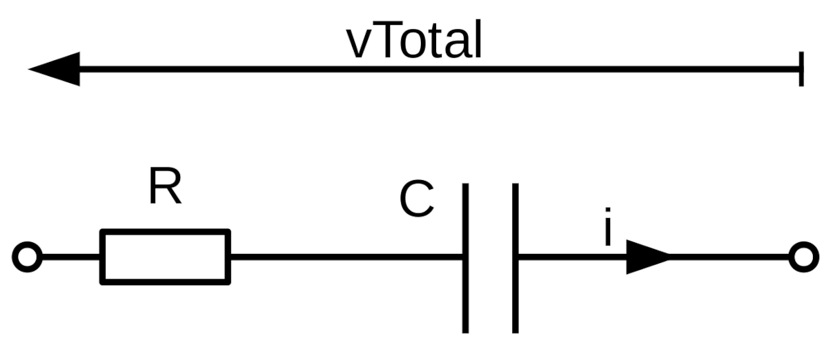
Figure 3.
Electrical results for a Raney1 coated 316SS electrode. (a) EIS measurements at three different signal amplitudes. Frequency range: 25 mHz to 10 kHz. (b) CV waveform recorded at 10 mV s −1. The simulation of the best-fit RQ network has been overlaid.
Figure 3.
Electrical results for a Raney1 coated 316SS electrode. (a) EIS measurements at three different signal amplitudes. Frequency range: 25 mHz to 10 kHz. (b) CV waveform recorded at 10 mV s −1. The simulation of the best-fit RQ network has been overlaid.

Figure 4.
Electrical performance of Raney2-coated 316SS for both HER and OER. Electrolyte: 1M KOH.

Figure 5.
Cyclic Voltammetry measurements for Raney2 at three different voltage sweep rates. (a) Plotted as conventional voltammograms, and (b) plotted as a function of time. The best-fit RQ network simulations have been underlaid under the transient waveforms.
Figure 5.
Cyclic Voltammetry measurements for Raney2 at three different voltage sweep rates. (a) Plotted as conventional voltammograms, and (b) plotted as a function of time. The best-fit RQ network simulations have been underlaid under the transient waveforms.

Figure 6.
Cyclic voltammetry starting at −0.5 V of a Raney2 cathode, (a) without and (b) with iR-correction. All sections with negative voltage and positive current were due to capacitance and hydride formation. Sweep rate: 10 mV s−1.
Figure 6.
Cyclic voltammetry starting at −0.5 V of a Raney2 cathode, (a) without and (b) with iR-correction. All sections with negative voltage and positive current were due to capacitance and hydride formation. Sweep rate: 10 mV s−1.

Figure 7.
Schematic diagram of potentiostat.


Table 1.
Best-fit parameter values for an RQ network to the EIS and CV results in Figure 3. The error values (if known) are listed in brackets. The equivalent double-layer capacitance has been calculated using Equation (3), and the roughness factor RF using Equation (4).
| Trace | n | RF | |||
|---|---|---|---|---|---|
| Ω cm2 | sn Ω−1 cm−2 | mF cm−2 | |||
| EIS at 10 | 8.57 (0.8%) | 0.148 (2.5%) | 0.68 (1.9%) | 166 | 4150 |
| EIS at 31 | 8.52 (0.7%) | 0.149 (2.2%) | 0.68 (1.6%) | 167 | 4180 |
| EIS at 100 | 8.47 (0.7%) | 0.188 (2.3%) | 0.60 (1.9%) | 255 | 6370 |
| CV at 10 −1 | 9.45 | 0.206 | 0.72 | 266 | 6650 |
Table 2.
Tafel slopes, overpotentials and overall water-splitting voltage for coating Raney2 in 1 KOH at laboratory temperature, as presented in Figure 4.
Table 2.
Tafel slopes, overpotentials and overall water-splitting voltage for coating Raney2 in 1 KOH at laboratory temperature, as presented in Figure 4.
| Coating | Reaction | Current | Tafel | Over- | Voltage |
|---|---|---|---|---|---|
| Density | Slope | Potential | |||
| mA cm−2 | mV dec−1 | mV | V | ||
| Raney2 | HER | 10 | 50 | 28 | |
| Raney2 | HER | 100 | 111 | 91 | |
| Raney2 | OER | 10 | 34 | 291 | |
| Raney2 | OER | 100 | 62 | 328 | |
| Raney2 | Both | 10 | 84 | 320 | 1.55 |
| Raney2 | Both | 100 | 173 | 419 | 1.65 |
Table 3.
Best-fit RQ network parameter values to the cyclic voltammetry waveforms in Figure 5b.
Table 3.
Best-fit RQ network parameter values to the cyclic voltammetry waveforms in Figure 5b.
| Ramp Rate | n | RF | |||
|---|---|---|---|---|---|
| mV s−1 | Ω cm2 | sn Ω−1 cm−2 | F cm−2 | ||
| 10 | 9.41 | 0.811 | 0.67 | 2.21 | 55,170 |
| 6.7 | 9.61 | 0.784 | 0.71 | 1.80 | 45,000 |
| 3.3 | 9.84 | 0.762 | 0.72 | 1.70 | 42,490 |
| Average | 9.62 | 0.786 | 0.70 | 1.89 | 47,150 |
Table 4.
Recent achievements in earth-abundant hydrogen evolution catalysis. All overpotentials quoted at 10 −2. Catalyst PtC is noble-metal, and included for comparison purposes only.
Table 4.
Recent achievements in earth-abundant hydrogen evolution catalysis. All overpotentials quoted at 10 −2. Catalyst PtC is noble-metal, and included for comparison purposes only.
| Lead Author(s) | Year | Catalyst | Substrate | Electrolyte | Tafel Slope mV dec | Overpotential mV |
|---|---|---|---|---|---|---|
| Wang Mingyong [48] | 2015 | NiMo | Cu | 10 wt% NaOH | 137 | 7 |
| Wang Yuhang [49] | 2014 | 3D NiMo | Cu foam | 1 NaOH | 11 | |
| Song Fuzhang [50] | 2018 | Ni3N/Ni | NF | 1 KOH | 12 | |
| C Panda [51] | 2019 | NiPt3@NiS | NF | 1 KOH | 24 | 12 |
| Yu Fang [52] | 2018 | FeP/Ni2P | NF | 1 KOH | 24.2 | 14 |
| Zhang Jian [53] | 2017 | MoNi4 / MoO2 | NF | 1 KOH | 30 | 15 |
| Zhang Tao [54] | 2018 | Ni5P4@NiCo2O4 | NF | 1 KOH | 27 | 27 |
| W. Gannon [37] | 2019 | Raney2 | 316SS | 1 KOH | 50 | 28 |
| R. Solmaz [28] | 2017 | NiZn-Au | Cu/Ni | 1 KOH | 66 | 31 |
| Men Yana [55] | 2019 | Ni−Co2P | CC | 1 KOH | 51 | 34 |
| Chen Weiwu [56] | 2019 | S-NiP | NF | 1 KOH | 44 | 35 |
| Herraiz-Cardona [57] | 2012 | Ni | Cu foam | 30 wt% KOH | 103 | 41 |
| Huang Yichao [58] | 2019 | 1T-MoS2 | CFP | 1 KOH | 52 | 43 |
| Xiang Rui [59] | 2019 | PtC | NF | 1 KOH | 53 | 46 |
| Xiang Rui [59] | 2019 | Co@CoMoO4 | NF | 1 KOH | 85 | 46 |
| Gao M. [60] | 2017 | Ni-Mo MS | Cu | 1 KOH | 49 | 49 |
| Liu Caichi [61] | 2020 | Ni2P−NiSe2 | CC | 1 KOH | 72.6 | 66 |
| Shi Zhangping [62] | 2016 | nano MoC | GCE | 1 KOH | 50 | 77 |
| Zhu Yanping [63] | 2019 | CoSe1.26P1.42 | CC | 1 KOH | 90 | 92 |
| Xing Zhicai [64] | 2016 | Ni3N | NF | 1 KOH | 109 | 121 |
| Lai Feili [65] | 2019 | Fe−NiCo2O4@HNCP | GCE | 1 KOH | 47 | 124 |
| Zhu Wenxin [66] | 2016 | NiS−MS | Ni foam | 1 KOH | 83 | 134 |
| Farjana Haque [67] | 2019 | 2D Crys-AMO | NF | KOH | 50 | 138 |
| Feng Yi [68] | 2016 | Ni-Co-P-300 | not known | 1 KOH | 61 | 150 |
| Liang Hai-Wei [69] | 2015 | CoNx | C | 1 KOH | 75 | 170 |
Table 5.
Recent achievements in earth-abundant oxygen evolution catalysis. All overpotentials quoted at 10 −2.
Table 5.
Recent achievements in earth-abundant oxygen evolution catalysis. All overpotentials quoted at 10 −2.
| Lead Author(s) | Year | Catalyst | Substrate | Electrolyte | Tafel Slope mV dec | Overpotential mV |
|---|---|---|---|---|---|---|
| Yu Fang [52] | 2018 | FeP/Ni2P | NF | 1 KOH | 22.7 | 154 |
| Gao Chen [70] | 2019 | Amorphous LaNiFe | NF | 1 KOH | 36 | 189 |
| Bo Zhang [71] | 2016 | Gelled FeCoW | Au-plated NF | 1 KOH | 191 | |
| Xiang Xu [72] | 2016 | NixFe1-xSe2−DO | NF | 1 KOH | 28 | 195 |
| Lu Xunyu, Zhao Chuan [73] | 2015 | NiFe NSh | NF | 1 KOH | 28 | 215 |
| Chi Jun [74] | 2018 | FeOOH/NiFe | CCH NA | 1 KOH | 220 | |
| Feng Yan [75] | 2017 | NiFe-N NSh | CC | 1 KOH | 26 | 224 |
| Liu Rong [76] | 2017 | CoFe LDH NSh | NF | 1 KOH | 36 | 232 |
| Nai Jianwei [77] | 2017 | Ni-Fe-Se disks | GCE | 1 KOH | 26 | 240 |
| Lu Xue Feng [78] | 2017 | CoFe2O4/C NRA | NF | 1 KOH | 45 | 240 |
| Wang Zhaoyang [79] | 2016 | NiFeSe NSh | CC | 1 KOH | 47 | 229 |
| Gong Ming [80] | 2013 | NiFe-LDH | CNT | 1 KOH | 31 | 247 |
| Lu Zhiyi [81] | 2014 | NiFe-LDH NP | Nickel | 1 KOH | 43 | 250 |
| Zhang Huabin [82] | 2019 | FeCoP nanoboxes | CFP | 1 KOH | 31 | 269 |
| Rodney Smith [83] | 2013 | Fe40%Ni60% | FTO | KOH | 34 | 284 |
| Xu You [84] | 2017 | Ni@NC-800 | NF | 1 KOH | 45 | 285 |
| Sengeni Anantharaj [85] | 2017 | CoP NSt | GC | 1 KOH | 70 | 287 |
| Yun-Pei Zhu [86] | 2015 | CoP-MNA | NF | 1 KOH | 65 | 290 |
| W. Gannon [37] | 2019 | Raney2 | 316SS | 1 KOH | 38 | 293 |
| Wang Huaping [87] | 2019 | LaFexNi1-xO3 NR | GCE | 1 KOH | 50 | 302 |
| Zhang Huabin [88] | 2019 | HCM@Ni-N | Carbon | 1 KOH | 76 | 304 |
| Song Fang, Xile Hu [89] | 2014 | CoMn LDH | GC | 1 KOH | 43 | 324 |
| Guang Liu [90] | 2016 | NiFe2O4 NR | GC | 1 KOH | 44 | 342 |
| Santosh Bikkarolla [91] | 2015 | CuCo2O4 | NrGO | 1 KOH | 64 | 360 |
| Jing Jiang [92] | 2014 | NiCo-LDH NSh | NF | KOH | 113 | 420 |
Publisher’s Note: MDPI stays neutral with regard to jurisdictional claims in published maps and institutional affiliations. |
© 2020 by the authors. Licensee MDPI, Basel, Switzerland. This article is an open access article distributed under the terms and conditions of the Creative Commons Attribution (CC BY) license (http://creativecommons.org/licenses/by/4.0/).
Share and Cite
MDPI and ACS Style
Gannon, W.J.F.; Dunnill, C.W. Study of Activity and Super-Capacitance Exhibited by Bifunctional Raney 2.0 Catalyst for Alkaline Water-Splitting Electrolysis. Hydrogen 2021, 2, 1-17. https://doi.org/10.3390/hydrogen2010001
AMA Style
Gannon WJF, Dunnill CW. Study of Activity and Super-Capacitance Exhibited by Bifunctional Raney 2.0 Catalyst for Alkaline Water-Splitting Electrolysis. Hydrogen. 2021; 2(1):1-17. https://doi.org/10.3390/hydrogen2010001
Chicago/Turabian StyleGannon, William J. F., and Charles W. Dunnill. 2021. "Study of Activity and Super-Capacitance Exhibited by Bifunctional Raney 2.0 Catalyst for Alkaline Water-Splitting Electrolysis" Hydrogen 2, no. 1: 1-17. https://doi.org/10.3390/hydrogen2010001