Abstract
Plasma-facing components (PFCs) are among the most critical functional components in a nuclear fusion device. Their reliability and durability under high heat loads are directly tied to the safe operation and lifetime of the fusion device. Under cyclic high thermal loads, accumulated plastic strain can lead to material property degradation. Furthermore, severe temperature gradients generate alternating tensile and compressive stresses within the material, resulting in the initiation and propagation of microcracks, ultimately causing structural failure of the PFCs. This study focuses on the issues of thermal stress concentration and plastic strain accumulation at the tungsten (W)/copper (Cu) joint interface and proposes an optimized design scheme based on a laminated tungsten structure. Using a combined approach of finite element simulation and theoretical analysis, the effects of tungsten layer thickness and interface geometry on the thermomechanical performance of the PFC joint were systematically investigated. The results indicate that reducing the thickness of tungsten sheet can significantly decrease the interfacial stress level. As the tungsten sheet thickness is reduced from the millimeter scale to the micrometer scale, the thermal mismatch at the W/Cu interface is reduced, thereby leading to a notable reduction in normal stress along the axial direction. In particular, when the thickness falls below 10 μm, the axial normal stress approaches zero, and the equivalent stress at the interface is effectively mitigated. Further research indicates that optimizing the flat W/Cu interface into an arc-shaped interface can alter the location of stress concentration. When the ascending distance of the Cu exceeds 600 μm, the stress concentration at the interface vertex is essentially eliminated. However, an excessively ascending distance of the Cu can exacerbate plastic deformation in the copper layer. By optimizing the extended distance of the Cu, a balance between stress relief and plastic strain accumulation can be effectively achieved.
1. Introduction
Tokamaks confine high-temperature plasma via strong magnetic fields and are considered the most promising devices for future controllable nuclear fusion. During operation, the nuclear fusion plasma deposits substantial amounts of high energy particles and extreme heat loads onto the inner wall. Plasma-facing components (PFCs) are designed to withstand these extreme thermal conditions and consist of three parts: the plasma-facing material (PFM), a thermal stress buffering interlayer, and the heat sink material [,]. Since tungsten (W) has excellent properties, including high melting point, low radiation sputtering, and low coefficient of thermal expansion, it is considered to be the most promising plasma-facing material []. CuCrZr is commonly used as a heat sink material due to its good thermal properties []. A soft copper (Cu) interlayer can reduce the thermal stress caused by mismatch of coefficient of thermal expansion (CTE) between W and CuCrZr []. However, W and Cu are immiscible and exhibit significant differences in both CTE and elastic modulus. Thermal stress tends to concentrate at the material interface, making it the most likely site for crack initiation [], which compromises the service life and reliability of the component. The interface between W and Cu has an important impact on the joint performance. Furthermore, the Cu interlayer is susceptible to plastic fatigue under high heat flux (HHF) loading conditions.
In large-scale fusion experiments such as ITER and DEMO, the steady-state heat flux [] on plasma-facing components is projected to reach 10 MW/m2 during stable plasma operation, and up to 20 MW/m2 during slow transient events. In addition, during plasma instabilities such as Edge Localized Modes (ELMs), transient thermal loads can attain magnitudes on the order of 100 MW/m2 within milliseconds [].
Long-term thermal loading imposes demanding requirements on the mechanical properties of plasma-facing components to withstand cyclic thermal stresses. Consequently, the development of high-quality joints for PFCs is an important area of plasma fusion research in tokamak []. Several PFC designs have been developed, among which the most effective are the monoblock and flat-type designs []. Jiang et al. [] fabricated four distinct micro/nano-interfacial structures via femtosecond laser processing, leading to enhanced mechanical performance in W/Cu joints. Li et al. [] considered the influence of the size parameters of the monolithic PFC on the plastic fatigue and fracture behavior of the target and speculated that the smaller size PFC has lower failure rates in terms of tungsten brittle cracking and copper interlayer plastic fatigue. Lu et al. [] applied microchannel cooling technology to reduce the thermal load on PFCs. Steady-state high heat flux testing and thermal fatigue evaluation demonstrated that this method is effective in mitigating heat loads on divertor targets. Tivey et al. [] designed a W brush-like structure, which accommodates the coefficient of thermal expansion mismatch between W and Cu. However, under certain conditions, it experiences significant creep deformation. Li et al. [] replaced the soft oxygen-free copper (OFCu) interlayer with a functional gradient material (FGM) interlayer. W-Cu FGMs transition from high W to high Cu, and by gradually changing the composition, CTE mismatch between W and Cu can be mitigated, thus reducing the thermal stress at the interface. The proposed laminated tungsten structure has been demonstrated to reduce surface damage induced by particle bombardment through a decrease in the axial thickness of the tungsten sheet [,]. Thermal fatigue tests conducted using an electron beam device on laminated tungsten samples with varying thicknesses confirmed that reducing the thickness of the tungsten sheets effectively mitigates surface crack damage [].
Therefore, preventing W/Cu interface cracking under high load is an effective way to improve the service life of PFC. This paper focuses on the connection between laminated W-PFM and interlayer Cu, studies the influence of W-PFM with different axial thickness on the overall thermal and mechanical properties of PFC, and introduces a special arc interface to disperse the stress at the interface. The finite element analysis method is used to calculate the stress and strain at the W/Cu interface under steady-state thermal load, and the overall performance of PFC focuses on the stress of W and the plastic strain of Cu. An optimization design for laminated W-PFM is proposed.
2. Finite Element Simulation Model
2.1. PFC Model
A flat-type PFC composed of laminated tungsten PFM was adopted as the analysis model. A three-dimensional elasto-plastic analysis was performed on a one-half model. The overall dimensions of the PFC are shown in Figure 1. The cross section of CuCrZr alloy is 20 mm × 20 mm rectangular; the inner diameter of the central water pipe channel is 10 mm and the outer diameter is 12 mm. The thickness of the pure copper interlayer is 1 mm. t is the axial (y-direction) thickness of the W-PFM is between 2 mm and 0.01 mm. Considering that the presence of gaps becomes non-negligible as t decreases, the length ratio of the tungsten to the gap in the y-direction was set to 20:1. To ensure model validity and accuracy, the tungsten, copper, and CuCrZr alloy were assumed to exhibit ideal elasto-plastic behavior, and the bilinear kinematic hardening model was applied to all materials. To accurately evaluate the stress and strain at the interface, the mesh near the W/Cu interface was sufficiently refined, and a smooth mesh transition was implemented along the Z-direction on the symmetry plane. A mesh independence study ensured numerical accuracy. For each tungsten thickness, the interfacial mesh was refined through thickness until variations in maximum von Mises stress and accumulated plastic strain fell below 2%, confirming convergence and stability across all simulations. Temperature-dependent material properties used in the model are provided in Table 1.
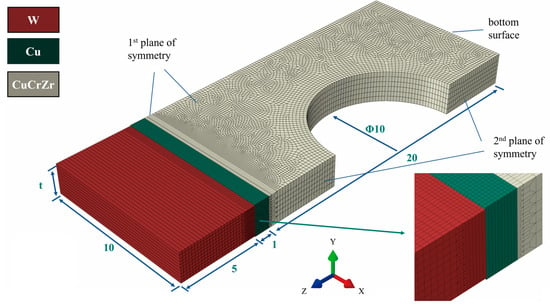
Figure 1.
Finite element model dimensions, mesh, and boundary conditions.

Table 1.
Thermal–physical properties of the considered materials at selected temperatures [,].
2.2. Boundary Conditions
A finite element analysis of the temperature, stress, and strain in the PFC model was conducted using an indirect coupling method. The underlying governing equations for the transient thermomechanical response are the classical heat conduction and mechanical equilibrium equations:
where is temperature, is time, is thermal conductivity, is density, is specific heat, and is the stress tensor.
In each heating cycle, a heat flux of 10 MW/m2 was uniformly applied to the top surface of the tungsten armor, constituting a Neumann-type thermal boundary condition, mathematically expressed as:
where is the applied heat flux of 10 MW/m2, and n is the unit normal vector outward from the surface. The initial model temperature was 20 °C. A pressure of 4 MPa was applied to the inner wall of the cooling tube to simulate the hydraulic pressure induced by the coolant water, which represents a Neumann-type mechanical boundary condition:
where denotes the coolant pressure of 4 MPa. The convective heat transfer coefficient on the inner surface of the cooling tube was set to 110,000 W/(m2·K), corresponding to a Robin (Mixed) boundary condition:
where is the convection coefficient of 110,000 W/(m2·K), and a is the coolant temperature of 100 °C. For the Stefan–Boltzmann radiation condition, an ambient temperature of 200 °C and a tungsten emissivity of 0.3 were applied to the loaded surface, forming a nonlinear Mixed boundary condition:
where is the emissivity, is the Stefan–Boltzmann constant, and is the ambient temperature. For the bottom surface of the PFC, the other side of the loading surface is set as a fixed constraint to simulate the connection of the component to the stainless steel bracket, imposing a Dirichlet boundary condition on displacement:
where u is the displacement vector. The temporal evolution of the heat flux applied to the top surface of the tungsten is shown in Figure 2. A total of five loading cycles were simulated to study the time-dependent behavior of temperature, stress, and strain. Each cycle consisted of 10 s of heating followed by 10 s of cooling. Perfect thermal contact was assumed at all material interfaces [,,,].
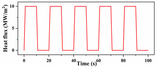
Figure 2.
Time evolution of heat flux loaded on top surface.
3. Results and Discussion
3.1. Thermomechanical Analysis
Simulations of the temperature history over five loading cycles were performed using the finite element software ABAQUS 2021. Figure 3a shows the thermal analysis results at t = 10 s (the end of the first heating phase), where the highest temperature occurs at the vertex region farthest from the cooling channel. The temperature evolution at this point throughout the cyclic process is presented in Figure 3b. During the heating phase, the temperature of the tungsten top surface increases rapidly and stabilizes after approximately 6 s. In the cooling phase, the temperature decreases quickly, and after 10 s of active cooling, the temperature of the entire PFC approaches that of the coolant water. The maximum temperature does not increase with the number of cycles, indicating that the cooling is sufficiently effective. The maximum temperature in the cycle process is only 791.7 °C, while the recrystallization of tungsten becomes obvious after 1200 °C at least, and the maximum temperature in the steady state does not reach the W recrystallization temperature, so the influence of W recrystallization on stress and strain is not considered.
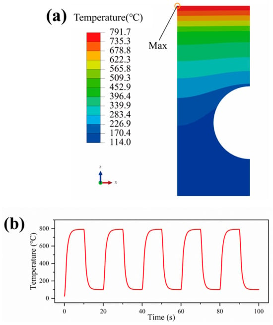
Figure 3.
(a) The temperature distribution in the tungsten monoblock after 10 s of heating at 10 MW/m2. (b) Time evolution of maximum temperature.
Figure 4 shows the trend of the maximum temperature of the tungsten with the thickness. Since the ratio of the tungsten thickness t to the gap width between the adjacent tungsten sheets was kept constant at 20:1, the ratio of the heated area to the heat dissipation area remained unchanged. Moreover, as heat is transferred primarily along the Z-direction toward the water cooling area, the vertical gaps have little effect on heat transfer. Therefore, the thickness t only has a minor influence on the maximum temperature of the tungsten during heating. Finite element results show that the temperature variation with thickness does not exceed 0.5 °C. In contrast, although the tungsten surface is also subjected to high thermal loads, its thermal stress response remains relatively moderate under the absence of external constraints, owing to its high strength at elevated temperatures and low coefficient of thermal expansion.
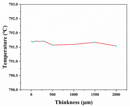
Figure 4.
The variation in PFC maximum temperature with thickness.
Figure 5a,b show the equivalent stress and cumulative plastic strain distribution nephograms at the end of the cyclic load (time = 100 s) for thickness t = 2 mm, respectively. The results show that the stress and plastic strain distribution regions of different thickness samples show similar characteristics. Under the thermal load, the equivalent stress and cumulative plastic strain are highly concentrated near the tungsten–copper interface. The extreme value of the equivalent stress appears on the tungsten side at the interface, while the extreme value of the cumulative plastic strain concentrates on the copper side at the interface, and these extreme values are distributed in the area far away from the center of the cooling channel.
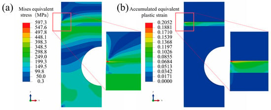
Figure 5.
Analysis results during the cooling period after 5 HHF cycles at t = 2 mm. (a) Mises equivalent stress distribution. (b) Accumulative equivalent plastic strain distribution.
This phenomenon can be attributed to the following reasons: as the distance from the water-cooled center increases, the temperature of the copper layer rises. Elevated temperatures significantly reduce the yield strength of the copper, promoting easier plastic deformation. Furthermore, plastic deformation in the copper induces work hardening, resulting in localized stress concentration.
Figure 6a shows the evolution of the Mises equivalent stress in the tungsten layers of different thicknesses during thermal cycling. The stress–time curves clearly indicate that the rate of increase in the peak equivalent stress during the cooling phase is significantly higher than that during the heating phase, and this difference becomes more pronounced with increasing material thickness. During the heating process, although the thermal expansion of the copper layer is restricted by the tungsten layer to generate compressive stress, the decrease in the elastic modulus of the copper under high temperature and the combined action of the plastic flow effect effectively relieve the stress accumulation, making the stress increase relatively gentle.
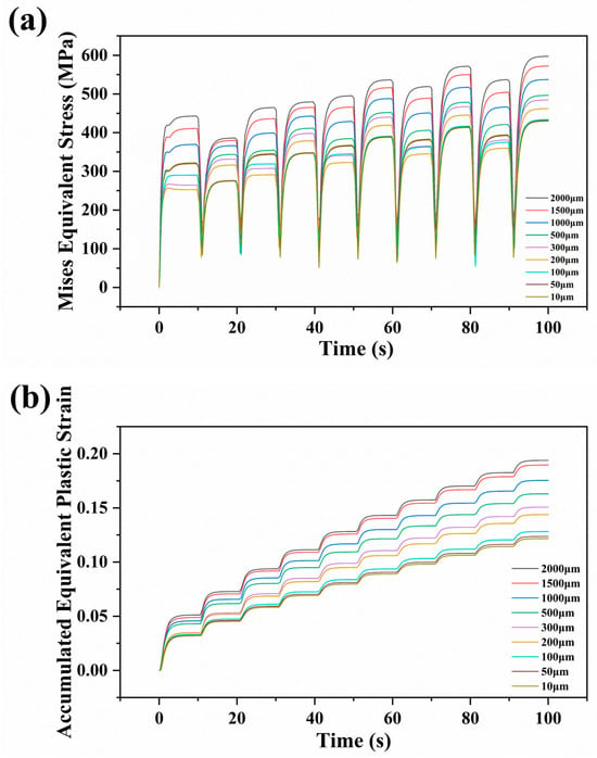
Figure 6.
(a) Variation in von Mises equivalent stress over time. (b) Variation in cumulative equivalent plastic strain over time.
During the cooling phase, the contraction of the copper layer is strongly constrained by the tungsten layer. As the temperature decreases, the elastic modulus of the tungsten gradually recovers, leading to a continuous increase in constraint stiffness. More importantly, irreversible plastic deformation generated during the heating stage interacts with and constrains the elastic recovery during cooling, resulting in greater deformation incompatibility. Meanwhile, the temperature-dependent differences in thermal contraction between the tungsten and the copper further amplify this mismatch, ultimately leading to a rapid increase in stress levels during the cooling stage.
Figure 7 reveals the significant influence of the tungsten sheet thickness on the interfacial stress state. The data show a clear positive correlation between the axial thickness of the W-PFM and the Mises equivalent stress, i.e., as the thickness increases, the level of equivalent stress also rises. However, when the thickness decreases below 100 μm, this increasing trend slows noticeably. Further analysis indicates that this phenomenon stems from the synergistic reduction in normal stresses in both the X and Y directions: when the thickness falls below 100 μm, the normal stresses in both directions exhibit a plateauing decline, with the Y-direction normal stress approaching nearly zero once the thickness reaches 10 μm. In particular, these stress data are collected at the end of the cycle load (the process equivalent stress reaches the maximum value).
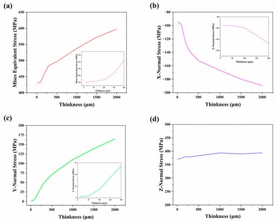
Figure 7.
Analysis results during the cooling period after 5 HHF cycles. (a) Mises equivalent stress, (b) X-direction normal stress, (c) Y-direction normal stress, (d) Z-direction normal stress.
From a mechanistic perspective, this size effect is primarily governed by the following factors. First, the normal stress in the Y direction decreases as the Y-direction thickness of the W-PFM is reduced. Second, due to the Poisson effect (), the normal stress in the X direction also decreases as the Y-direction normal stress diminishes. When the Y-direction normal stress approaches zero, the coupled X-direction normal stress correspondingly stabilizes. It is worth noting that the Z-direction normal stress exhibits relatively low sensitivity to the thickness of the tungsten structure, indicating distinct variation characteristics among the three principal normal stress components.
Figure 8 further illustrates the cumulative plastic strain variation with tungsten thickness. Similar to the stress variation trend, the cumulative plastic strain also decreases with the decrease in the thickness of the tungsten sheet and shows a significant trend reduction when the thickness of the tungsten sheet is less than 100 μm. Sensitivity analysis confirmed the robustness of conclusions under varying heat flux and coolant temperatures.
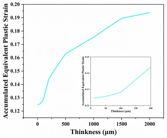
Figure 8.
Accumulative equivalent plastic strain variation with thickness.
The mechanism underlying the reduction in both equivalent stress and plastic strain with decreasing thickness is illustrated in Figure 9. The interfacial mechanical behavior between the tungsten and the copper during thermal cycling originates primarily from the mismatch in their thermal expansion properties. During the heating phase, the copper layer exhibits a greater tendency to expand thermally due to its higher coefficient of thermal expansion. However, as the two materials are mechanically bonded at the interface, the free expansion of copper is constrained, resulting in a compressive stress field within the copper layer. When this stress exceeds the material’s yield strength, irreversible compressive plastic deformation occurs. In the subsequent cooling process, since the copper layer has undergone plastic deformation during the heating phase, its shrinkage behavior differs from elastic recovery. The copper layer shrinks more than the tungsten layer, but this difference is limited by the interface constraints, which create tensile stress inside the copper layer and residual compressive stress in the tungsten layer.
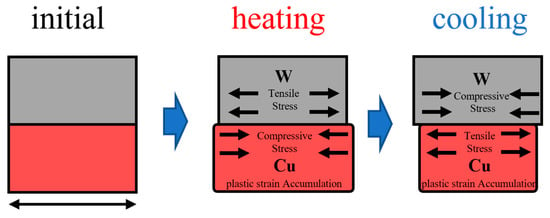
Figure 9.
The influence mechanism of thickness on interface stress/strain during thermal cycling process.
According to the theory of thermal expansion, assuming an initial thickness t, the free thermal deformations of the two materials under unconstrained conditions are given by
where and represent the free thermal deformations of the tungsten and the copper, respectively; and denote the coefficients of thermal expansion of the tungsten and the copper, respectively; and ΔT is the temperature change.
Owing to the strong interfacial constraint, the actual thermal mismatch deformation, , can be expressed as
It is noteworthy that both the degree of interfacial stress concentration and the accumulation of plastic strain are positively correlated with . Therefore, as the thickness t of the W-PFM decreases, the value of is reduced, thereby effectively mitigating interfacial stress concentration and plastic strain accumulation. This size effect offers an effective approach to regulating the interfacial stress–strain state. By optimizing the geometric dimensions, the thermal fatigue resistance of PFCs can be significantly improved without altering the material composition. This study demonstrates that reducing tungsten thickness mitigates interfacial stress and plastic strain by controlling δ, thereby extending the geometric optimization strategy beyond suppressing surface cracking [], while also providing a means to address the key low-cycle fatigue failure driver identified in standard W/Cu monoblock designs [].
3.2. Analysis of Optimization Results for the PFC Structure
3.2.1. Interface Optimization Design
Given the significant pressure and plastic strain at the interface resulting from the thermal expansion mismatch between the tungsten and the copper, replacing the flat W/Cu interface with a curved geometry can alleviate stress concentration. However, this may lead to an overly narrow (sharp) geometry in the oxygen-free copper region, which is unfavorable for sufficient deformation. Therefore, the Cu and CuCrZr regions are extended outward in the X direction to provide adequate deformation space, as illustrated schematically in Figure 10. Throughout the design process, the vertical distance between the top surface of tungsten and the lowest point of the curved interface, as well as the distance from that point to the center of the cooling channel, remain unchanged. The shape of the interface is controlled by two parameters: the vertical rise height H of the highest point of the Cu region and the lateral extension distance D of the Cu/CuCrZr boundary in the X direction. The meshed model of the designed structure is also shown in Figure 10. Paths A-A and B-B are defined to better account for the effect of the structure on temperature and interface stresses.
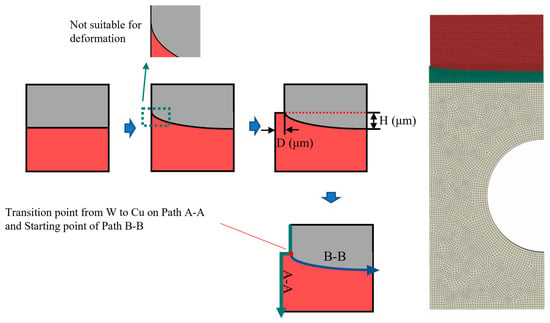
Figure 10.
Interface optimization design process and mesh.
3.2.2. Influence of Parameters H and D on Thermal–Mechanical Properties of PFC
Simulation results indicate that optimizing the W/Cu interface from a flat to a curved geometry leads to a significant influence of parameters H and D on the thermomechanical performance of the PFC. As the ascending distance of Cu (H) increases, the volume fraction of highly thermally conductive copper grows, leading to a noticeable decrease in the maximum temperature on the tungsten surface. At the same time, due to the reduced distance between the Cu and the heating zone (upper surface of tungsten), there is a temperature rise in the Cu ascending zone (shown as the inflection point of the image), and this redistribution of the temperature field is clearly shown in Figure 11 and directly affects the thermal stress state of the PFC.
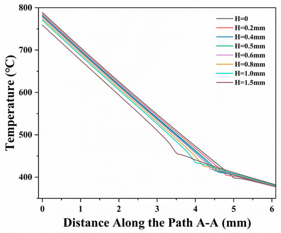
Figure 11.
The influence of H on the temperature distribution on path A-A (D = 100 μm).
From the perspective of stress distribution, the introduction of the curved interface significantly alleviates the original stress concentration issue. As the value of H increases, the concentrated stress that originally appeared at the tungsten vertex away from the cooling channel in the W/Cu interface is effectively relieved. By analyzing the distribution of the stress path along B-B (Figure 12a), it is clearly observed that at the initial stage of the increase in the value of H, the left-side stress peak point gradually shifts towards the central region. When H exceeds 600 μm, the left position is no longer the maximum point of interface stress, which fully demonstrates that the arc interface has excellent stress release capacity. Further analysis shows that the maximum stress at the interface decreases continuously with the increase in H (Figure 12b), and when H exceeds 600 μm, the position of the maximum stress shifts to the area above the pipe center. The stress here is mainly from the extrusion of the surrounding tungsten on the central area, and the arc interface becomes relatively straight at this place, so the impact of the arc interface on the stress in this area is relatively limited, and the reduction trend tends to be stable.
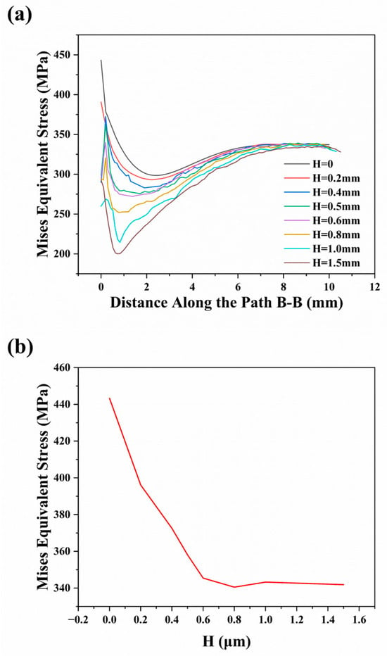
Figure 12.
Influence of parameter H on stress distribution. (a) Mises equivalent stress along path B-B. (b) Maximum stress at the W/Cu interface (D = 100 μm).
A nonlinear variation in plastic strain behavior has been observed, as illustrated in Figure 13. As the value of H increases, the accumulated plastic strain exhibits an initial decrease followed by a sharp increase. The initial decline indicates that an appropriately designed interface geometry can effectively mitigate stress concentration and reduce plastic deformation. However, the subsequent rapid increase can be attributed to two main factors. The first is the continued rise in H, which leads to elevated temperature in the copper region, resulting in accelerated material softening and promoting further plastic strain. The second is the significant alteration in the geometry of the copper zone, which reduces the space available for deformation.
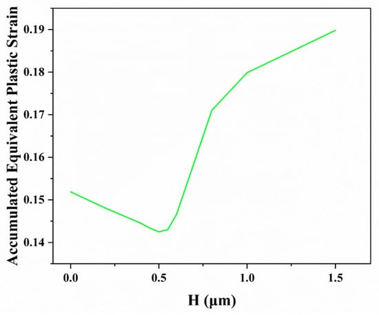
Figure 13.
The trend of maximum cumulative equivalent stress of PFC in HHF process with respect to H (D = 100 μm).
By reducing the thickness of the tungsten sheet and optimizing the interface shape, the stress of the tungsten is far less than the allowable stress, and the fatigue life of the joint is estimated based on the plastic strain data of irradiated copper, so the reduction in plastic strain under steady-state thermal load is more important []. Considering the sharp increase in plastic strain in copper under large values of H, the influence of the lateral extension distance D of the Cu (CuCrZr) region on the performance of the W/Cu joint was systematically investigated under a fixed arc height of H = 1500 μm. The results are shown in Figure 14. As the value of D increases, the temperature field and mechanical response of the material system exhibit regular changes. In terms of thermal properties, the increase in D value reduces the maximum operating temperature of the tungsten and the copper, and the temperature drop of the copper is obvious. In terms of mechanical properties, increasing the value of D can further reduce the interface stress. The main reason is that increasing the value of D will reduce the overall temperature of PFC.

Figure 14.
The impact of D on finite element results. (a) The maximum temperature of W and Cu, (b) Maximum stress of W. (c) The maximum cumulative equivalent plastic strain of Cu.
In-depth analysis reveals that an increase in the value of D influences the plastic behavior of the copper through two key mechanisms. On one hand, a larger D provides more space for material deformation and makes the strain distribution more coordinated. On the other hand, the reduced operating temperature effectively suppresses the plastic deformation capability of the copper. It is worth noting that this improvement effect exhibits a distinct size threshold: once D exceeds 500 μm, the decreasing trend in plastic strain slows significantly, indicating that the expanded space has largely satisfied the requirement for deformation release. More importantly, practical engineering constraints prevent D from increasing indefinitely—excessive D would increase the gap between adjacent PFCs, exposing the copper region to the risk of direct plasma bombardment.
4. Conclusions
This study investigates the W/Cu interface in flat-type plasma-facing components (PFCs) for nuclear fusion devices, with a focus on systematically exploring the influence of the axial thickness of tungsten sheets in laminated tungsten plasma-facing material (PFM) and interface geometry optimization on the thermomechanical performance of PFC joints. Using a combined approach of finite element simulation and theoretical analysis, this work reveals inherent correlations between geometric parameters and thermomechanical behavior, providing an important theoretical basis for the reliability design of key fusion device components. The findings can be summarized as follows:
- (1)
- Laminated tungsten PFM: It was found that as the axial thickness of the tungsten sheets decreases from the millimeter scale to the micrometer level, the thermal mismatch deformation δ in the Y direction between the tungsten and the copper exhibits a significant decreasing trend. This geometric size effect directly leads to a systematic reduction in the normal stress in the Y direction at the interface. When the thickness is reduced to 10 μm, the normal stress in the Y direction approaches nearly zero. This phenomenon fundamentally confirms the notably improved thermal deformation compatibility of the materials at the micrometer scale, offering a new approach for regulating interfacial stress.
- (2)
- In the study on interface geometry optimization, the conventional flat interface was modified into a curved structure. Experimental data indicate that as the distance H of the highest point of the Cu region increases, the stress concentration zone undergoes significant spatial redistribution, shifting gradually from the initial tungsten vertex location toward the central area. Quantitative analysis shows that when the value of H exceeds 600 μm, stress concentration no longer occurs at the original vertex position. This improvement effectively mitigates the risk of interfacial fatigue failure, thereby enhancing the service life of the PFC joint.
- (3)
- The study further revealed that interface optimization must be coordinated with the overall structural design. As H gradually increases, the deformation space within the Cu/CuCrZr region becomes progressively constrained. By increasing the value of D, sufficient space for deformation accommodation can be provided, thereby reducing plastic strain in copper. This geometric compatibility relationship fundamentally reflects a dynamic balance between the material’s deformation capacity and external constraints. Its optimization design requires comprehensive consideration to achieve the optimal balance between stress relief effectiveness and structural reliability.
Author Contributions
Original draft, J.L.; methodology, J.L.; investigation, Y.Q.; supervision, B.W. (Bing Wang); review, B.W. (Bo Wang); editing, B.W. (Bo Wang). All authors have read and agreed to the published version of the manuscript.
Funding
This work was supported by the National Natural Science Foundation of China (NO. 52104374) and the Hebei Province Central Leading Local Science and Technology Development Fund Project (NO. 236Z1004G).
Data Availability Statement
The data presented in this study are available on request from the corresponding author.
Conflicts of Interest
The authors declare no conflicts of interest.
References
- El-Morshedy, S.E.-D. Thermal-hydraulic modelling and analysis of ITER tungsten divertor monoblock. Nucl. Mater. Energy 2021, 28, 101035. [Google Scholar] [CrossRef]
- Jiang, M.; Pan, Z.; Huang, S.; Zhou, Z.; Su, Y. Thermomechanical measurements for a flat-type divertor mock-up: A benchmark for simulation. Nucl. Mater. Energy 2023, 36, 101483. [Google Scholar] [CrossRef]
- Zhou, Z.; Pintsuk, G.; Linke, J.; Ma, Y.; Roedig, M. Performance of the different swaged tungsten grades under transient high heat loads. Phys. Scr. 2009, T138, 014058. [Google Scholar] [CrossRef]
- Wei, B.; Zhou, R.; Xu, D.; Chen, R.; Chen, P.; Cheng, J. Achieving high-strength W/W-10Cu joints by vacuum diffusion bonding with FeCoCu interlayer. Fusion Eng. Des. 2023, 191, 113553. [Google Scholar] [CrossRef]
- Crescenzi, F.; Bachmann, C.; Richou, M.; Roccella, S.; Visca, E.; You, J.-H. Design study of ITER-like divertor target for DEMO. Fusion Eng. Des. 2015, 98–99, 1263–1266. [Google Scholar] [CrossRef]
- Richou, M.; Gallay, F.; Chu, I.; Li, M.; Magaud, P.; Missirlian, M.; Rocella, S.; Visca, E.; You, J.H. Status on the W monoblock type high heat flux target with graded interlayer for application to DEMO divertor. Fusion Eng. Des. 2017, 124, 338–343. [Google Scholar] [CrossRef]
- Li, M.; You, J.-H. Cracking behavior of tungsten armor under ELM-like thermal shockloads II: A revised prediction for crack appearance map. Nucl. Mater. Energy 2016, 9, 598–603. [Google Scholar] [CrossRef]
- Gwon, H.; Takeuchi, Y.; Kasada, R.; Konishi, S. Evaluation of heat transfer by sublimation for the application to the divertor heat sink for high fusion energy conversion. Fusion Eng. Des. 2014, 89, 1003–1008. [Google Scholar] [CrossRef]
- Khirwadkar, S.S.; Singh, K.P.; Patil, Y.; Khan, M.S.; Buch, J.J.U.; Patel, A.; Tripathi, S.; Jaman, P.M.; Rangaraj, L.; Divakar, C. Fabrication and characterization of tungsten and graphite based PFC for divertor target elements of ITER like tokamak application. Fusion Eng. Des. 2011, 86, 1736–1740. [Google Scholar] [CrossRef]
- Alba, R.; Iglesias, R.; Angeles Cerdeira, M. Materials to Be Used in Future Magnetic Confinement Fusion Reactors: A Review. Materials 2022, 15, 6591. [Google Scholar] [CrossRef]
- Jiang, D.; Long, J.; Han, J.; Cai, M.; Lin, Y.; Fan, P.; Zhang, H.; Zhong, M. Comprehensive enhancement of the mechanical and thermo-mechanical properties of W/Cu joints via femtosecond laser fabricated micro/nano interface structures. Mater. Sci. Eng. A-Struct. Mater. Prop. Microstruct. Process. 2017, 696, 429–436. [Google Scholar] [CrossRef]
- Li, M.; You, J.-H. Structural impact of armor monoblock dimensions on the failure behavior of ITER-type divertor target components: Size matters. Fusion Eng. Des. 2016, 113, 162–170. [Google Scholar] [CrossRef]
- Lu, M.; Han, L.; Zhao, Q.; Qiu, J.; Zhou, J.; Hu, D.; Mou, N.; Chen, X. Microchannel cooling technique for dissipating high heat flux on W/Cu flat-type mock-up for EAST divertor. Plasma Sci. Technol. 2022, 24, 095602. [Google Scholar] [CrossRef]
- Tivey, R.; Ando, T.; Antipenkov, A.; Barabash, V.; Chiocchio, S.; Federici, G.; Ibbott, C.; Jakeman, R.; Janeschitz, G.; Raffray, R.; et al. ITER divertor, design issues and research and development. Fusion Eng. Des. 1999, 46, 207–220. [Google Scholar] [CrossRef]
- Li, Q.; Xie, C.; Wang, W.; Wang, J.; Wang, X.; Gao, Q.; Chen, Z.; Peng, W.; Yang, Z.; Luo, G.-N. Optimization of W/Cu monoblock mock-up with FGM interlayer for CFETR devertor targets. Fusion Eng. Des. 2019, 147, 111262. [Google Scholar] [CrossRef]
- Song, H.; Qi, C.; Peng, J.; Guo, P.; Lai, J.; Cheng, L.; Yuan, Y.; Wang, B.; Lu, G. Resistance to deuterium-induced blistering in laminated microstructure tungsten. Nucl. Mater. Energy 2025, 43, 101921. [Google Scholar] [CrossRef]
- Xiao, S.; Ma, Y.; Tian, L.; Li, M.; Qi, C.; Wang, B. Decrease of blistering on Helium irradiated tungsten surface via transversal release of helium from the grooved surfaces. Nucl. Mater. Energy 2020, 23, 100746. [Google Scholar] [CrossRef]
- Qi, C.; Qi, Y.; Song, H.; Wang, X.; Xiao, S.; Wang, B. Finite Element Analysis and Experimental Verification of Thermal Fatigue of W-PFM with Stacked Structure. Metals 2024, 14, 555. [Google Scholar] [CrossRef]
- Li, C.; Zhu, D.; Wang, B.; Chen, J. Theoretical analysis on the damages for tungsten plasma facing surface under superposition of steady-state and transient heat loads. Fusion Eng. Des. 2018, 132, 99–106. [Google Scholar] [CrossRef]
- Wang, S.-M.; Li, J.-S.; Wang, Y.-X.; Zhang, X.-F.; Ye, Q. Thermal Shock Behavior Analysis of Tungsten-Armored Plasma-Facing Components for Future Fusion Reactor. Acta Metall. Sin.-Engl. Lett. 2018, 31, 515–522. [Google Scholar] [CrossRef]
- Wang, Y.; Wang, H.; Mi, B.; Zhao, J.; Zhang, C. Microstructure-based crack formation in tungsten exposed to cyclic transient heating. J. Nucl. Mater. 2023, 583, 154555. [Google Scholar] [CrossRef]
- Panayotis, S.; Hirai, T.; Barabash, V.; Amzallag, C.; Escourbiac, F.; Durocher, A.; Komarov, V.; Martinez, J.M.; Merola, M. Fracture modes of ITER tungsten divertor monoblock under stationary thermal loads. Fusion Eng. Des. 2017, 125, 256–262. [Google Scholar] [CrossRef]
- Zhang, K.; von Mueller, A.; Greuner, H.; You, J.-H. Stress analysis of divertor plasma-facing component designs using tungsten particle-reinforced copper composite heat sink. Fusion Eng. Des. 2020, 154, 111510. [Google Scholar] [CrossRef]
- Li, M.; You, J.-H. Interpretation of the deep cracking phenomenon of tungsten monoblock targets observed in high-heat-flux fatigue tests at 20 MW/m2. Fusion Eng. Des. 2015, 101, 1–8. [Google Scholar] [CrossRef]
- Li, M.; Werner, E.; You, J.-H. Low cycle fatigue behavior of ITER-like divertor target under DEMO-relevant operation conditions. Fusion Eng. Des. 2015, 90, 88–96. [Google Scholar] [CrossRef]
Disclaimer/Publisher’s Note: The statements, opinions and data contained in all publications are solely those of the individual author(s) and contributor(s) and not of MDPI and/or the editor(s). MDPI and/or the editor(s) disclaim responsibility for any injury to people or property resulting from any ideas, methods, instructions or products referred to in the content. |
© 2025 by the authors. Licensee MDPI, Basel, Switzerland. This article is an open access article distributed under the terms and conditions of the Creative Commons Attribution (CC BY) license (https://creativecommons.org/licenses/by/4.0/).