
Effects of Carboxyl Functionalized CNT on Electrochemical Behaviour of Polyluminol-CNT Composites
by
 , , ,
, , ,
Raunaq Bagchi
1,*,
Mohamed Elshazly
1,2,
Jeanne N’Diaye
3,
Dian Yu
1,
Jane Y. Howe
1 and
Keryn Lian
1,* 1
Department of Materials Science and Engineering, University of Toronto, Toronto, ON M5S 3E4, Canada
2
The Edward S. Rogers Sr. Department of Electrical & Computer Engineering, University of Toronto, 10 King’s College Road, Toronto, ON M5S 3G4, Canada
3
Beckman Institute for Advanced Science and Technology, University of Illinois at Urbana-Champaign, 405 N Mathews Ave, Urbana, IL 61801, USA
*
Authors to whom correspondence should be addressed.
Chemistry 2022, 4(4), 1561-1575; https://doi.org/10.3390/chemistry4040103
Submission received: 1 October 2022
/
Revised: 9 November 2022
/
Accepted: 9 November 2022
/
Published: 11 November 2022
(This article belongs to the Section Electrochemistry and Photoredox Processes)
Abstract
:The effect of carboxyl groups on the redox activity of polyluminol-carbon nanotube composites was studied. Carboxyl groups were selected due to their known contributions toward surface wettability and pseudocapacitance while often present on naturally derived low-cost porous carbons. Density functional theory (DFT) predicted energetically favoured bonding and a significantly reduced band gap between the luminol and carboxylated graphene relative to that of bare graphene, suggesting improved charge storage for carboxylated carbon substrates. The prediction was validated using bare carbon nanotubes (CNTs) and carboxylated CNTs (COOH-CNTs) as the substrates for in situ chemical polymerized luminol (CpLum). Surface morphological studies showed a ca. 1.1 nm thick coating of CpLum on CNT (CpLum/CNT) and a ca. 1.3 nm on COOH-CNT (CpLum/COOH-CNT), while surface chemical analysis revealed ca. 10% nitrogen from CpLum on both CpLum/CNT and CpLum/COOH-CNT. However, with merely 4.4% of COOH functionalization, CpLum/COOH-CNT was able to store more charge (137.1 ± 17.1 C cm−3) relative to CpLum/CNT (86.1 ± 14.1 C cm−3) and had increased charge retention over 5000 cycles. The insights from these studies can be used to engineer the surface of carbons such as CNTs and ACs to improve the interfacial properties for redox active materials and composites.
1. Introduction
The mounting demand for clean energy and environmental sustainability has led to the rising interest in redox-active organic-carbon composite electrodes for high power and long-lasting energy storage, especially for electrochemical capacitors (EC) [1,2,3]. Nitrogen-containing organic redox-active materials such as the conducting polymers polyaniline (PANI), and polypyrrole (PPy) have been extensively investigated in the literature as components of redox-active composites due to their strong redox activities [4,5,6,7].
Polyluminol is a conducting polymer with strong redox activity and can be leveraged in composites [8,9,10,11]. Chemically polymerized luminol (CpLum) on multi-walled carbon nanotubes (CNT) showed increased capacitive charge storage properties in the composite (CpLum-CNT). With merely a few nm CpLum, the composite electrodes exhibited reversible faradaic redox reactions and stored ca. 2–3 times higher volumetric charge than that of bare CNT.
Among first principles modelling, density functional theory (DFT) leveraging quantum mechanical approximations of electron densities has been widely leveraged to understand the intrinsic properties of 2-D materials [12,13] and the interactions of organic molecules such as aniline [14], on 2-D monolayers such as coronene or graphene [15,16]. This DFT-based approach modelling a luminol monomer on graphene has been used to predict π-π interactions between the polymer and the CNT substrate. These interactions are thought to stabilize the composite and contribute to its strong electrochemical performance [8,17].
To further increase the charge storage capability, the interactions and surface chemistry between the redox active species and the carbon substrate need to be explored [2]. Among commonly found oxygen functional groups, carboxyl groups provide increased surface wettability [18,19] and charge storage through pseudocapacitance [20] while being present on naturally derived porous carbons such as carbonized and activated carbons (ACs) [21]. Furthermore, carboxyl functionalities can be introduced onto carbon surfaces through acid treatments involving H2SO4/HNO3 mixtures, allowing the surface functionalities to be tuned [18,22]. Surface carboxyl groups might promote the adsorption of the monomers such as luminol onto the surface of carbons prior to in situ chemical polymerization as reported in absorption studies involving carboxylic acid functionalized carbon and organic pollutants [23], dyes [24], and enzyme molecules [25]. Carboxyl groups have also served as tethering points for PANI [26] and PPy [27,28] during in situ oxidative polymerization on CNTs, which may be leveraged for polyluminol.
In this work, we investigated the effects of carboxylic groups on CNT towards the redox activities of the CpLum-CNT composites. The surface and electrochemical properties of the COOH-functionalized CNT CpLum composites (CpLum/COOH-CNT) were compared to the CNT composites (CpLum/CNT). The insights from this study can be used to engineer the surface of carbons such as CNTs and ACs [29] to improve the interfacial properties for redox active composite electrodes.
2. Materials and Methods
2.1. Materials
Luminol monomer was purchased from Alfa Aesar. Ammonium persulfate, dimethyl sulfoxide (DMSO), isopropyl alcohol (IPA) solvent and polytetrafluoroethylene (PTFE) 60% wt. aqueous dispersion were purchased from Aldrich. Multiwalled carboxylated carbon nanotubes (COOH-CNT) and bare carbon nanotubes (CNT) were purchased from US Research Nanomaterials, Inc. (Houston, TX, USA).
2.2. Polyluminol-CNT Composites
The CNTs were mixed with 5% by weight of the binder PTFE. The COOH-CNT and binder solution was mixed with IPA and left to dry under ambient conditions. The dried slurry-like mixture was placed on a pasta roller to compress and form 100–200 μm free-standing films [8].
Luminol was polymerized in situ on either CNT or COOH-CNT to produce chemically polymerized luminol on CNTs (CpLum/CNT) and (CpLum/COOH-CNT) through the following sequence: free-standing CNT or COOH-CNT films were immersed in 20 mL DMSO-water mixture (9:1) dissolved with 0.35 g of luminol followed by the addition of 0.19 g of ammonium persulfate and letting the reaction proceed for 3 h at room temperature. The carbon films were then repeatedly washed in deionized water to remove excess products.
2.3. Material Characterizations
Surface morphological characterizations were performed through scanning electron microscopy (SEM) using the secondary electron signals from a Hitachi SU-7000 SEM in beam deceleration at a landing voltage of 1 kV. The presence of surface coating and its thickness was also studied using transmission electron microscopy (TEM) with a Hitachi HF-3300 cold FE-TEM operated at 100 kV. The samples were prepared by dry-casting dispersed materials onto a holy-carbon film supported on a 200-mesh copper TEM grid. for analysis in both SEM and TEM. Surface chemical composition analysis was performed using X-ray photoelectron spectroscopy (XPS) with a Thermo Scientific™ K-Alpha X-ray photoelectron spectrometer using a monochromated Al Kα source.
2.4. Electrochemical Characterizations
The electrochemical measurements were taken using a Princeton Applied Research PARSTAT MC Multichannel potentiostat. The free-standing carbon films were tested in a 3-electrode cell setup using a cavity microelectrode as the working electrode, Ag/AgCl reference electrode, a graphite counter electrode and 1 M H2SO4 as the electrolyte. The films were loaded into the 3.5 × 10⁻⁶ cm−3 cavity by compressing the microelectrode (CME) into films [30]. A minimum of 10 samples were tested for each composition. In the voltametric studies, each sample was tested at scan rates of 15 mV s−1, 50 mV s−1, 100 mV s−1, 500 mV s−1 and 1 V s−1.
2.5. First Principles Methods
The planewave pseudopotential implementation of Kohn–Sham Density Functional Theory (DFT) was used to model a luminol molecule adsorbed to a carboxyl-functionalized graphene substrate. Flat graphene is a reasonable approximation of the local CNT surface when considering that the diameters of the CNTs used in this work are 10-20 nm while our DFT-optimized structures show that the maximum Euclidean distance between two atoms within the luminol molecule is 7 Å. This means that the average local CNT curvature underneath luminol is 4.8°, which is nearly flat. Additionally, previous ab-initio studies of single-walled CNTs with metallic chirality show that their band structures are nearly identical to flat graphene within 1 eV of the Fermi level [31], which is sufficient to approximate the most interesting physicochemical interactions between CNT and adsorbate.
The simulation cell was built to contain a single luminol molecule within an infinitely periodic 9 × 9 carboxyl-functionalized graphene supercell, which ensures at least 10 Å of vacuum between the luminol molecule and its lateral periodic image to avoid spurious interactions. The supercell also includes 20 Å of vacuum along the vertical axis to ensure no spurious interaction between the luminol molecule and the graphene’s bottom in the periodic image. The graphene supercell contains 189 carbon atoms in the graphene layer, which is functionalized by 9 carboxyl groups. Including the luminol, this corresponds to an atomic oxygen percentage of 8.25% in the simulation cell, which lies within the experimentally measured range of 6.7 ± 2.1% in CpLum/COOH-CNT.
Simulations were conducted using the Quantum ESPRESSO package [32,33] version 6.4.1 with the revised VV10 [34] van der Waals exchange-correlation functional and projector augmented-wave pseudopotentials [35,36]. The energy cut-offs for wave functions and charge density are 820 and 9800 eV, respectively. A Monkhorst–Pack [37] grid of 4 × 4 × 1 was used to discretize and sample the supercell’s reciprocal space in all structural relaxation and self-consistent field runs. A denser grid of 8 × 8 × 1 was used for the density of states calculations. Bengtsson dipole corrections [38] were added to eliminate spurious electrostatic interactions between the supercell and its images due to the asymmetry of the layered structure along the vertical axis. Structural convergence criteria were set such that the total energy variation between structures is below 1.5 × 10⁻³ eV and each component of atomic forces is below 2 × 10⁻² eV Å−1. All graphical rendering of structures and data grids was conducted using XCrysDen [39]. Bader charge analysis was conducted using the Bader code [40,41,42,43].
3. Results and Discussion
The interaction of luminol on COOH-graphene compared to bare graphene was investigated through first-principles methods to provide a prediction for the effect of the functionality present. This was leveraged to design the composite, where the presence of CpLum on the surface of COOH-CNT was confirmed through material characterizations. The electrochemical behaviour was characterized and then compared with CpLum on bare CNT, to reveal the effect of the carboxyl group functionalization.
3.1. First Principles Analysis
To better understand the adsorption energetics of luminol in the presence of carboxyl-functionalized graphene, a luminol molecule was simulated in three separate adsorption sites relative to the underlying carboxyl groups: atop1, atop2, and interstitial. The three adsorption configurations are shown in Table 1. Atop1 and atop2 luminol molecules both began relaxation in a horizontal position above the carboxyl groups. Atop1 luminol was centred above a row of carboxyl groups, while atop2 luminol was situated at the same height, but above the gap between rows of carboxyl. Interstitial luminol began relaxation in between rows of carboxyl closer to the surface of graphene. Ultimately, both atop1 and atop2 luminol molecules ended up angling towards the carboxyl groups closest to their amine or NH edges. Most notably, the interstitial luminol ended up binding with the carboxyl groups and removing them off the graphene surface.
To compare the likelihood of adsorption at each site, the adsorption energy was calculated for all structures using Equation (1):
where is the total energy of the system containing luminol and COOH-graphene, is the total energy of the isolated luminol molecule, and is the total energy of the isolated COOH-graphene; with all three structures relaxed to their minimum energy configuration. A negative indicates that the formation of the combined luminol/COOH-graphene structure is exothermic, and therefore that adsorption will be energetically favourable.
of the three adsorbed structures are given in Table 1. While the negative signs of indicate that all three configurations are energetically favourable, the interstitial site is at least twice as energetically favourable as any of the atop sites. It is worth noting that the adsorption energy of luminol on bare graphene was found to be −0.97 eV, which means that carboxyl functionalization enhanced luminol adsorption regardless of its surface orientation. Due to its high energetic favourability and the prohibitive computational cost of such large DFT simulations, all further analysis will be limited to the interstitial adsorption configuration.
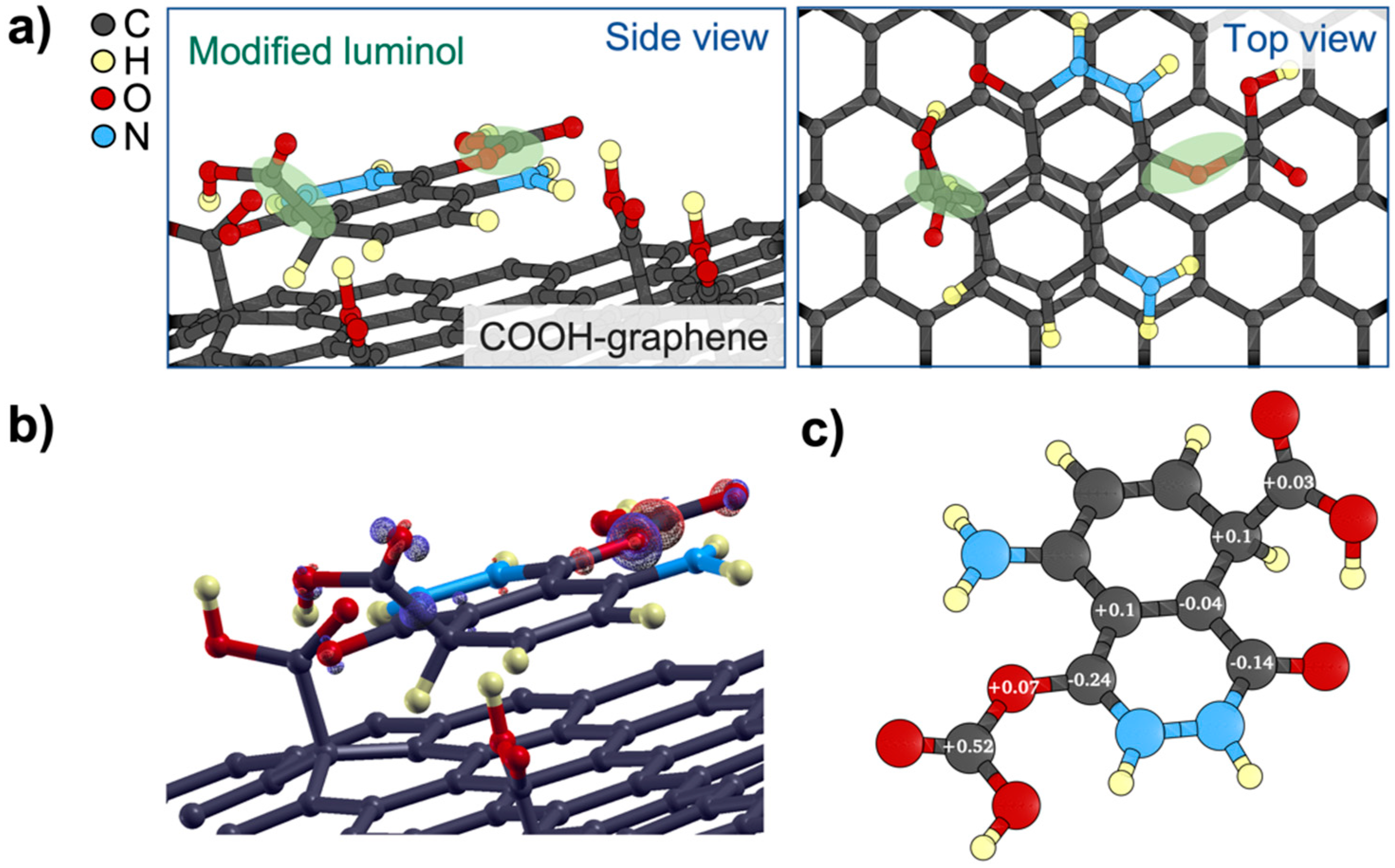
Beyond its favourable adsorption, the interstitial configuration is particularly interesting due to the likely formation of new bonds between luminol, and the surface carboxyl groups. Figure 1a shows close-up top and side views of interstitial luminol-COOH-graphene. The figure shows the formation of two new bonds between luminol and carboxyl (highlighted in green). When normalized per atom in luminol, the adsorption energy is in the order of 10 meV for the atop configurations and 100 meV for the interstitial configuration. This serves as the first piece of evidence that at least one of new bonds may be covalent, since the range for physisorption does not typically exceed the 10 meV atom−1 order of magnitude.
Two more pieces of evidence for the covalent nature of the new bonds can be found in Figure 1b,c, showing the difference in electron charge density (∆r) and the difference in Bader charges in luminol upon adsorption, respectively. ∆r is defined in Equation (2) as:
where is the electronic charge density of the system containing luminol adsorbed to COOH-graphene, is the charge density of the isolated luminol molecule, and is the charge density of the isolated COOH-graphene surface; with the isolated luminol and COOH-graphene structures fixed at their respective configurations favoured upon adsorption. The carboxyl groups bonded to luminol are included in the data grid.
Figure 1b shows that ∆ isosurfaces of ±0.2 eV Å−3, which are the highest visible isosurfaces in the data grid, are indeed localized around the bonding sites of carboxyl to luminol and their nearest neighbours. This can be quantitatively confirmed by the differences in Bader charges shown in Figure 1c. Most notably, the carbon in the carboxyl group bonded to luminol’s carbonyl has gained an additional +0.52e ionic charge following adsorption. This is a significant valence charge redistribution that suggests the formation of a new covalent bond. Noteworthy charge redistributions of −0.24e and +0.1e were also found in luminol’s carbonyl near the bonding site and another carbon atom at the bonding site with the other carboxyl group. In general, while Figure 1b shows where the strongest charge redistribution is localized, Figure 1c confirms the presence of covalent bonds with at least one of the carboxyl groups and serves as a heat map for charge reorganization within luminol’s molecular orbitals upon bonding with carboxyl.
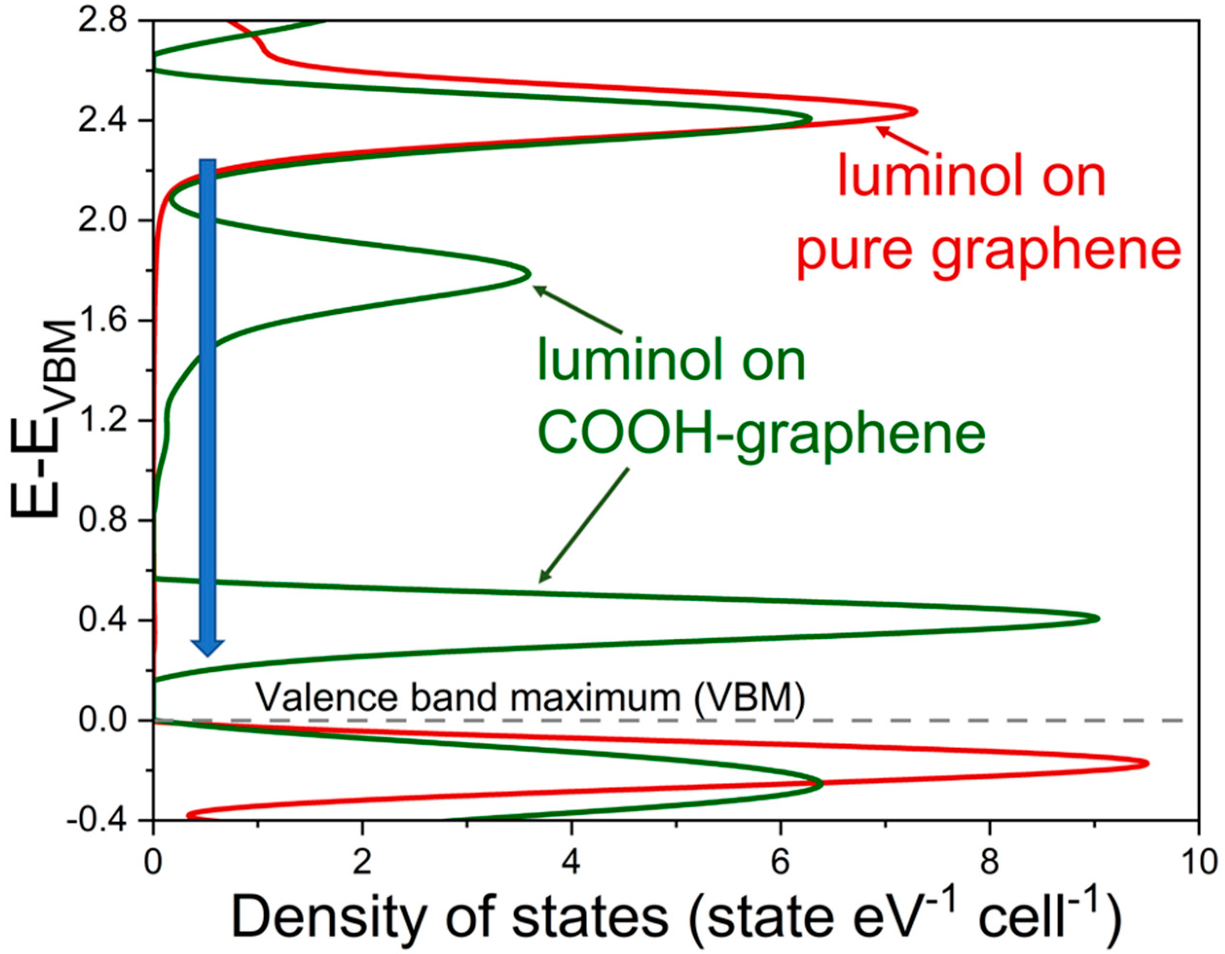
Beyond the characterization of bonds and charge reorganization, understanding the electrochemical behaviour of CpLum COOH-graphene requires investigating the influence of this carboxyl modification on the electronic structure of luminol. Figure 2 compares the projected Density of States (pDOS) produced through the linear combination of atomic orbitals in the luminol species adsorbed to pure graphene versus to COOH-graphene. Simulations for luminol on pure graphene were purpose-built for this work to provide benchmark values for pDOS and were conducted using parameters and methods identical to those previously reported in the Methods Section 2.5. The figure shows significant qualitative and quantitative changes in electronic structure due to COOH-graphene adsorption. Most notably interaction with carboxyl groups created additional electronic states above the Valence Band Maximum (VBM) with peaks at 0.4 eV and 1.8 eV, which possessed higher DOS and reduced the HOMO-LUMO gap from 2.2 to 0.2 eV. This gap reduction with higher DOS may be the underlying cause of the improved performance exhibited by CpLum/COOH-CNT composites compared to CpLum/CNT [44].
It is important to note that these new energy bands forming closer to the VBM upon adsorption to COOH-graphene are an intrinsic change in the luminol’s molecular orbital structure, and not simply additional orbitals associated with the bonded carboxyl groups. A comparison between the pDOS in Figure 2 and that including the contribution of the carboxyl-modified luminol groups can be found in the supplementary material (Figure S1). The pDOS of luminol and carboxyl-modified luminol (interstitial) on COOH-graphene confirmed that only additional densities of states are introduced without altering the HOMO-LUMO gap (Figure S1). This highlighted the importance of the transition from pure graphene to COOH-graphene to reduce the HOMO-LUMO gap for luminol.
3.2. Material Surface Structure and Functionality Analysis
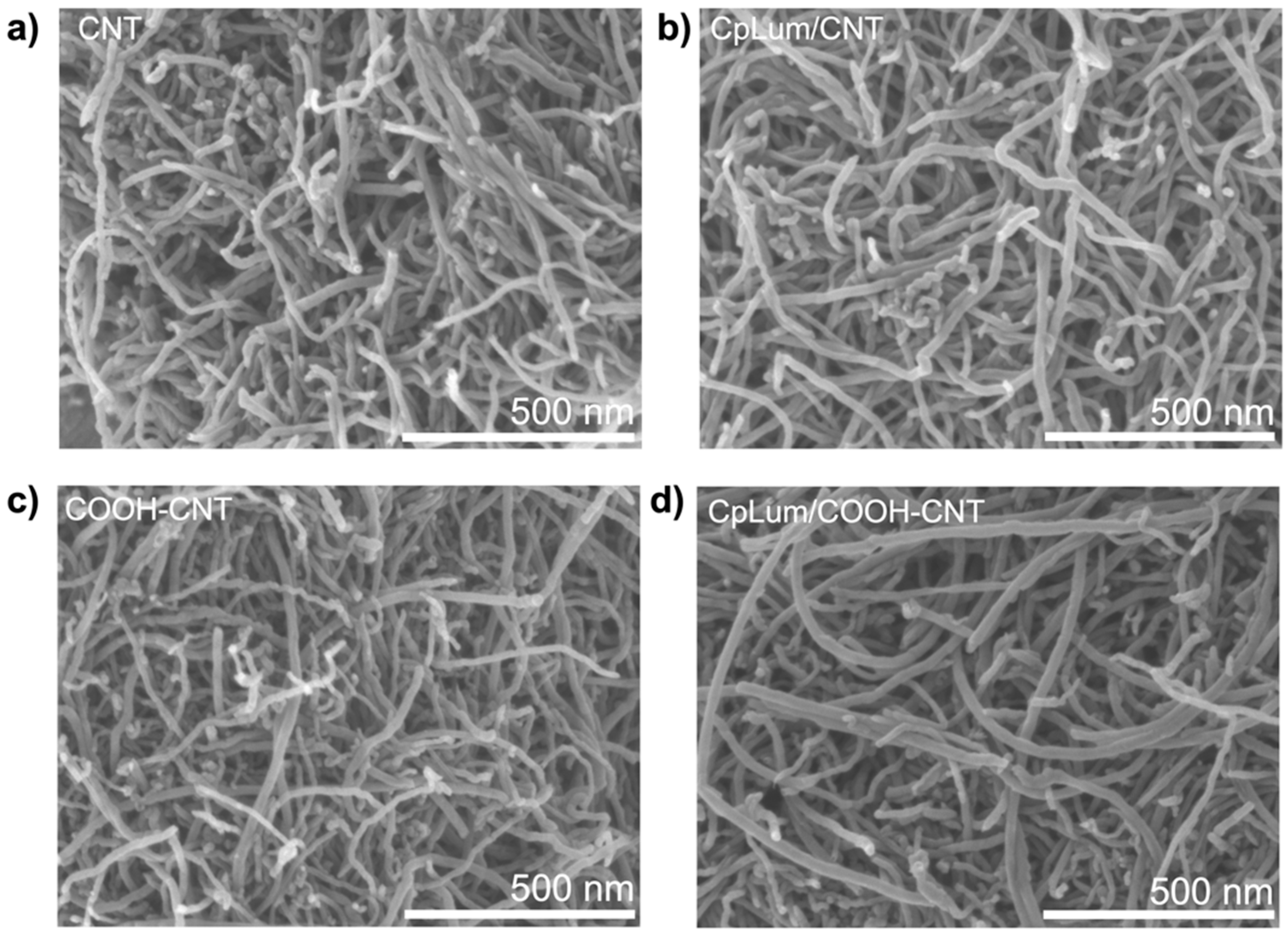
The surface morphology of CNT, CpLum/CNT, COOH-CNT and CpLum/COOH-CNT was investigated using SEM (Figure 3), which revealed tubular and open macropore structures. Following the CpLum coating, the comparison of Figure 3a vs. Figure 3b and Figure 3c vs. Figure 3d indicates similar morphology for the coated samples. The measured CNT tube diameters as summarized in Table 2 revealed an average CpLum coating of ca. 1.1 nm on CNT and a slightly thicker apparent coating of ca. 1.3 nm on CpLum/COOH-CNT.
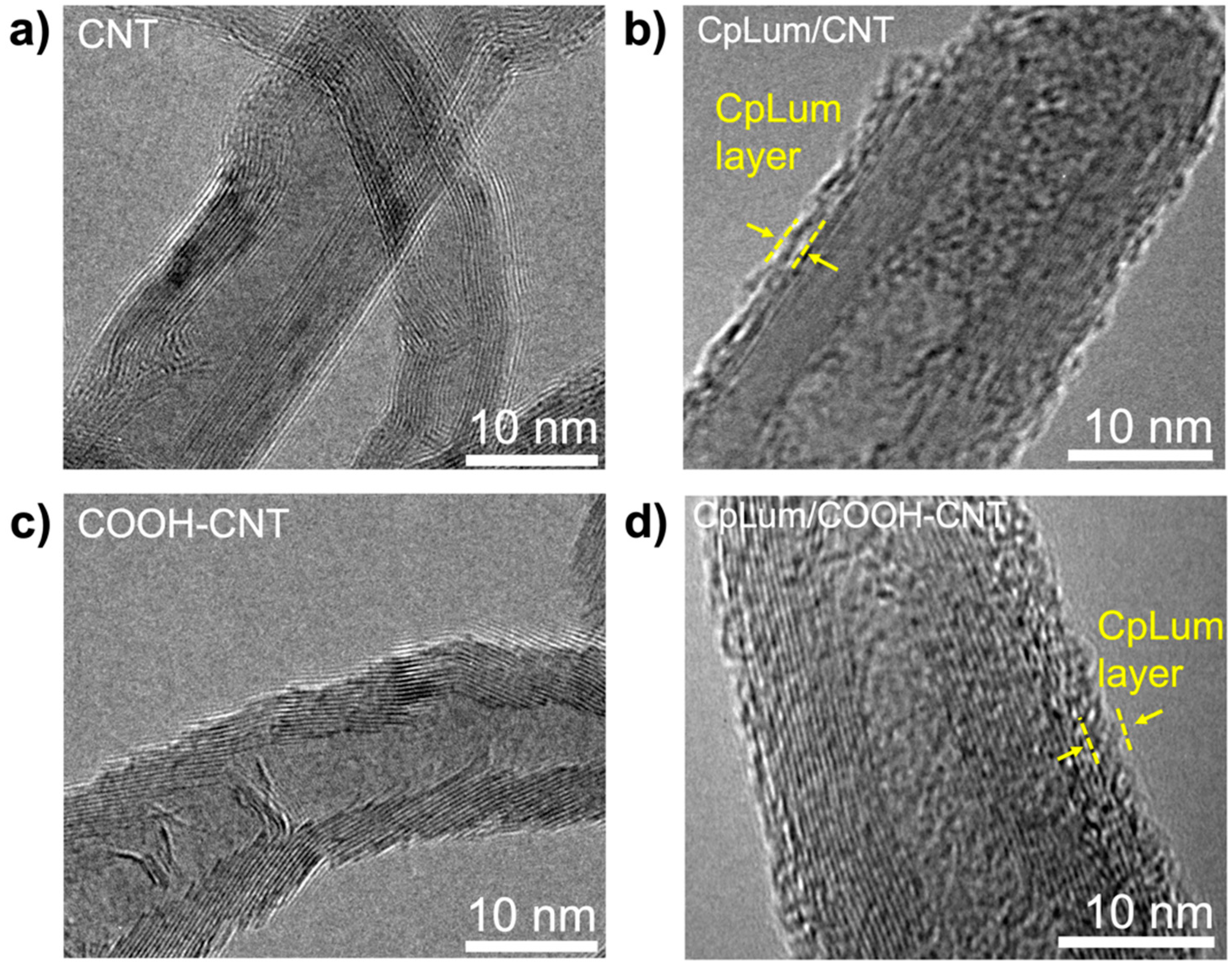
To further probe the tube surface, TEM micrographs were acquired showing the ordered tube walls of the CNT in Figure 4a and coated in Figure 4b. The nm-thick coating in CpLum/CNT was seen to cover most of the CNT surface, which is consistent with previous observations by N’Diaye et al. [8]. The COOH-CNT had slightly disordered tube walls (Figure 4c), possibly due to the concentrated acid chemistry during COOH functionalization [45]. After the coating on these rougher, functionalized tube walls, the CpLum/COOH-CNT composite exhibited a thin layer of CpLum ca. 1–2 nm in thickness well distributed across the surface (Figure 4d).
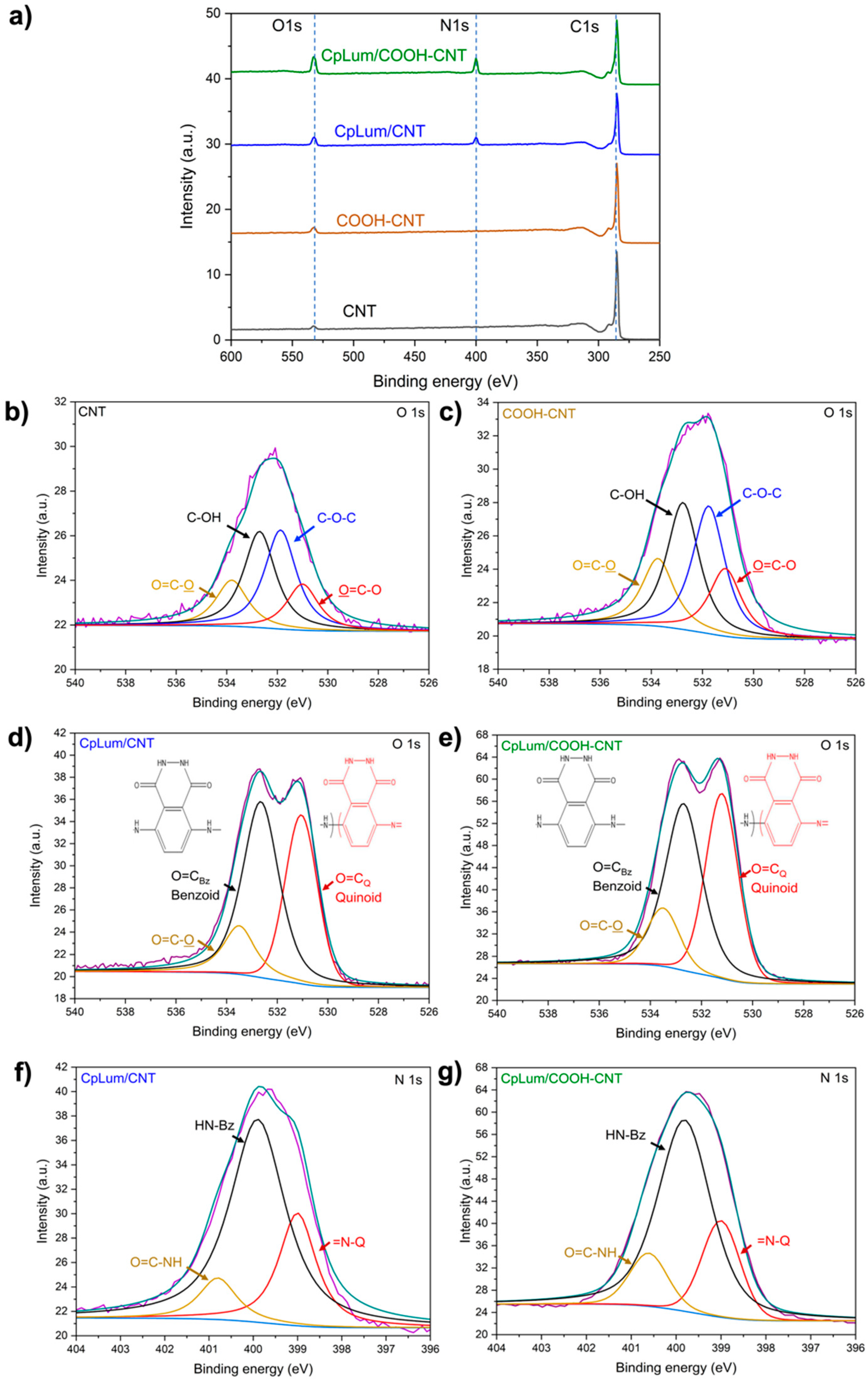
The presence of the CpLum coating on CNT and COOH-CNT is confirmed with the XPS survey spectra (Figure 5a) as indicated by the N1s peak from CpLum [11]. A summary of the elemental compositions is provided in Table 3 where the intensities of the peaks were compared after normalization by the different cross-sections. On the substrates, COOH-CNT has a higher concentration of O species owing to the additional carboxyl functionalities present. Further evidence of coating was provided by the high-resolution O 1s peaks (Figure 5b–e). The singlet peaks of CNT (Figure 5b) and COOH-CNT (Figure 5c) highlighted the distribution of peaks from C-O (C-O-C and C-OH) and COOH groups (O=C-O and O=C-O) [46,47]. Thus, COOH-CNT possessed a total of ca. 3% of its surface oxygen in COOH groups, translating to ca. 4.4% carboxyl group coverage on the CNT surface. Following CpLum coating, the O 1s peaks for CpLum/CNT (Figure 5d) and CpLum/COOH-CNT (Figure 5e) exhibited doublets, which are the signatures of carbonyl group from quinoid (O=CQ) and benzoid (O=CBz) subunits in CpLum [8,11]. The similar atomic percentages of N 1s for CpLum/CNT and CpLum/COOH-CNT indicate an identical level of the CpLum coating. The deconvolution of the high-resolution N 1s peaks for CpLum/CNT (Figure 5f) and CpLum/COOH-CNT (Figure 5g) revealed the key O=C-N-H polymerization signatures which are comparable. Notably, the overall benzoid (reduced) subunits observed in the CpLum is relatively higher for CpLum/COOH-CNT than that for CpLum/CNT, possibly indicating a role in changing the electronic states in the composite [48]. The functional groups and bonds deconvoluted using high-resolution peaks are summarized in Table S1 with high-resolution C 1s peaks showing the rich-surface functionalities for CpLum/CNT and CpLum/COOH-CNT in Figure S2.
3.3. Electrochemical Analysis
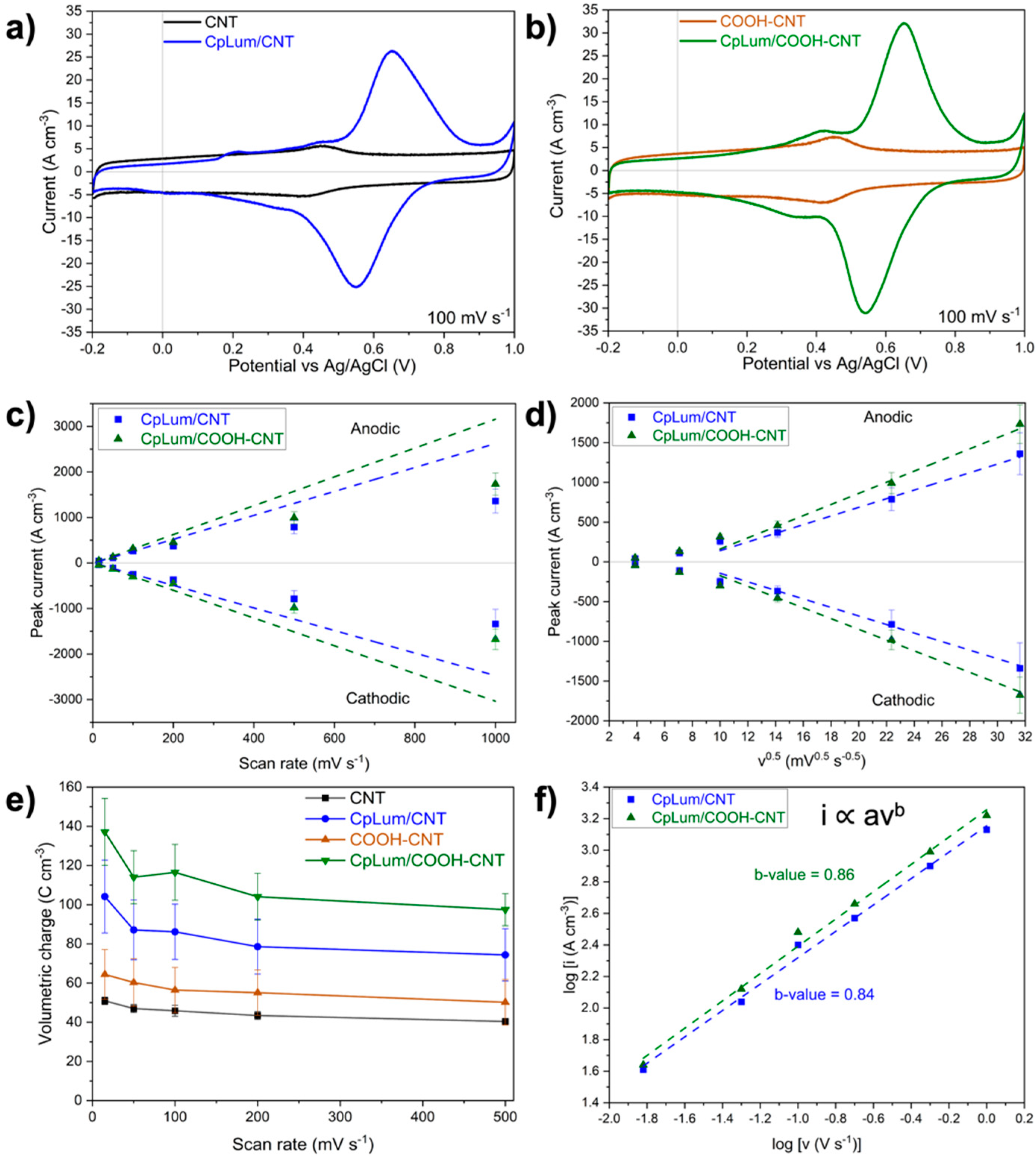
The redox activity of CpLum on unfunctionalized CNT involves a pair of anodic and cathodic peaks at 0.66 V and 0.56 V, respectively at 100 mV s−1 (Figure 6a). For CpLum/COOH-CNT, the redox peaks were stronger than those of CpLum/CNT while maintaining their potentials with a comparable peak separation of 0.11 V (Figure 6b). CpLum/CNT had a capacity 86.2 ± 14.1 C cm−3, about 88% increase from the baseline CNT, whereas CpLum/COOH-CNT achieved 116.5 ±14.2 C cm−3, a ca. 115% increase in charge stored relative to bare COOH-CNT. This charge enhancement is more significant at lower scan rates as illustrated in Table S2. An analogous charge storage increase was observed in the literature by Liu et al. for COOH-functionalized GO with PANI due to strong π-π interactions between the carboxyl groups on GO and PANI [49]. Similarly, Chaabani et al. observed increased oxidation for ciprofoxacin on COOH-functionalized CNT on glassy carbon electrodes citing a decrease in interfacial charge-transfer resistance [50].
To investigate the redox peak kinetics, the anodic and cathodic peak currents as a function of sweep rate, v, and the square root of scan rate, v0.5, were plotted in Figure 6c,d for both CpLum/CNT and CpLum/COOH-CNT. Both composite electrodes had relatively linear responses up to 100 mV s−1, suggesting largely surface control and fast kinetics at these rates. At the higher scan rates, peak currents of both composites were proportioned linearity against v0.5, indicating of diffusion control as expected owing to the limitation of ion movement at high scan rates. The performance of charge stored at different rates is summarized in Figure 6e.
To study the redox peak kinetics and the mechanisms of charge storage, the peak current was further related to the scan rate via Equation (3) [51]:
where i is the peak current, is the scan rate, a is a constant, and b (or b-value) is the slope of the plot of log (i) vs. log (). The b-value indicates which charge storage mechanism may be dominating: between 0.5 and 0.8 signifying diffusion-controlled (battery-type) processes; between 0.8 and 1 representing surface capacitive or electrical double layer (EDL) dominated processes. Across rates, the anodic and cathodic b-values for CpLum/CNT and CpLum/COOH-CNT (Figure 6f and Table S3) exceed 0.8. This indicates a combined surface capacitive and bulk diffusion (battery-type) but with the fast surface faradaic reactions and double-layer capacitive processes being more dominating.
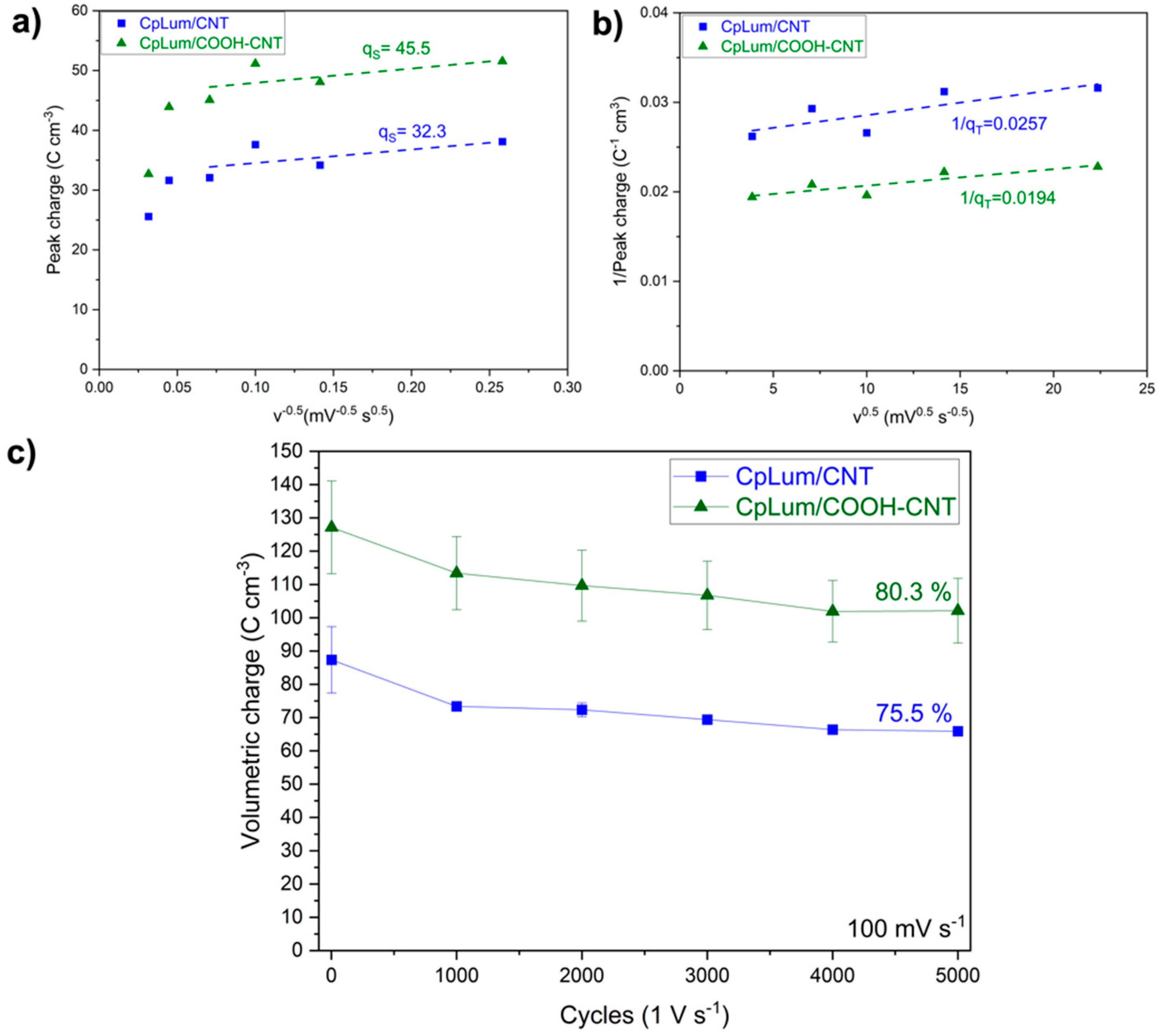
Another approach to differentiate the diffusion and surface-controlled peak charge stored was proposed by Trasatti, which provided an approximate deconvolution of these components regardless of the peak shifting behaviour observed at higher scan rates [52]. The method involves a theoretical maximum charge stored (qT) at scan rates approaching zero. This maximum peak charge is estimated using the intercept (1/qT) of the line-of-best fit from the inverse charge or 1/q plot vs. v0.5 (Figure 7a). The surface capacitive or EDL contribution to the total charge stored, qS, can be derived from the charge, q, against v−0.5 plot with extrapolation from lower scan rates (Figure 7b). The deconvolutions of the diffusion-limited and surface-limited charges for CpLum/CNT and CpLum/COOH-CNT are summarized in Table 4. On top of higher redox peak current and charge storage on CpLum/COOH-CNT, it also possesses 86% surface-controlled peak charge, which is higher than that of CpLum/CNT (83%) counterpart. This comparison suggests a similar distribution of charge-storage mechanisms on both composites. However, the increased charge storage on CpLum/COOH-CNT does not compromise the fast reaction kinetics.
In addition to high charge storage and fast kinetics, energy storage applications require stability over several thousands of charge/discharge cycles. To investigate the stability, cycle life of CpLum/CNT and CpLum/COOH-CNT composites were compared (Figure 7c). The higher charge of CpLum/COOH-CNT is also marginally better retained than that of the CpLum/CNT over long cycles. This indicates the stability of the composite is higher with COOH- functionality on CNT substrate.
Although there are no significant apparent differences in surface morphology (Figure 3) and only 4.4% of COOH groups on the surface (Table 2), there is a distinguished difference in the charge storage capability and stability. The increased charge storage occurs while slightly increasing the percentage of surface capacitive processes and maintaining fast kinetics. This may be attributed to the energetically favoured luminol deposition and smaller HOMO-LUMO band gap of CpLum/COOH-CNT predicted from the DFT models.
4. Conclusions
The effects of surface carboxyl groups on CNT on the behaviour of CpLum/CNT composites were investigated by the first principles, surface morphology and chemical composition as well as electrochemical analyses. First-principles DFT calculations predicted significantly more stable adsorption energies and a reduced HOMO-LUMO gap (2 eV to 0.2 eV) for three different luminol positions on COOH-graphene relative to that of luminol on pure graphene which could promote electrochemical redox activity. The thin, surface coating of CpLum/CNT (ca. 1.1 nm thick) and CpLum/COOH-CNT (ca. 1.3 nm thick) was confirmed with SEM/TEM analysis, with further surface elemental evidence provided by XPS.
Electrochemical analyses showed that while both composites had significant increases in charge storage over their CNT baselines, the CpLum/COOH-CNT had higher charge storage (ca. 35%), better rate performance and longer cycle life than that of CpLum/CNT. Further, b-value analysis and Trasatti’s method showed similar surface control dominated processes in CpLum/CNT and CpLum/COOH-CNT, suggesting both fast surface redox processes and double-layer capacitance occurring with marginally higher b-values and surface-controlled peak charge for CpLum/COOH-CNT.
The work has demonstrated that even small quantities of surface carboxyl groups can be leveraged to improve the charge storage of organic redox active coatings on composites, as they can provide desirable electronic interactions. These results underline the importance of considering the effect of surface functionalities on carbon materials and tuning them when designing redox active composites for charge storage.
Supplementary Materials
The following supporting information can be downloaded at: https://www.mdpi.com/article/10.3390/chemistry4040103/s1, Figure S1. A comparison between the pDOS of luminol and carboxyl modified-luminol adsorbed to COOH-graphene; Figure S2. High-resolution C 1s spectra of CpLum/CNT (left) and CpLum/COOH-CNT; Table S1. Bonding group percentages in CpLum/CNT and CpLum/COOH-CNT; Table S2. Summary of total charge storage at 15 mV s−1 and 100 mV s−1; Table S3. b-values for CpLum/CNT and CpLum/COOH-CNT.
Author Contributions
Conceptualization, R.B., K.L. and M.E.; methodology, R.B., M.E., D.Y., J.N., J.Y.H. and K.L.; software, R.B. and M.E.; formal analysis R.B., M.E., D.Y., J.N., J.Y.H. and K.L.; writing—original draft, R.B., M.E., D.Y. and K.L.; writing—review and editing, R.B., M.E., D.Y., J.N., J.Y.H. and K.L.; visualization, R.B., M.E. and D.Y.; supervision, J.Y.H. and K.L. All authors have read and agreed to the published version of the manuscript.
Funding
This research was funded by the Natural Sciences and Engineering Research Council of Canada (NSERC) NSERC-NFRFE-2019-00739 and NSERC-RGPIN-2022-04801.
Data Availability Statement
Not applicable.
Acknowledgments
The authors would like to appreciate the financial support from the Natural Sciences and Engineering Research Council of Canada (NSERC-NFRFE-2019-00739 and RGPIN-2022-04801). R.B. acknowledges the Queen Elizabeth II/Eleanor and Burnett Thall Graduate Scholarship for Science & Technology and the Hatch Graduate Scholarship for Sustainable Energy Research.
Conflicts of Interest
The authors declare no conflict of interest.
References
- Simon, P.; Gogotsi, Y. Materials for electrochemical capacitors. Nat. Mater. 2008, 7, 845–854. [Google Scholar] [CrossRef] [PubMed] [Green Version]
- N’Diaye, J.; Bagchi, R.; Howe, J.; Lian, K. Redox Active Organic-Carbon Composites for Capacitive Electrodes: A Review. Sustain. Chem. 2021, 2, 407–440. [Google Scholar] [CrossRef]
- Wang, Y.; Song, Y.; Xia, Y. Electrochemical capacitors: Mechanism, materials, systems, characterization and applications. Chem. Soc. Rev. 2016, 45, 5925–5950. [Google Scholar] [CrossRef] [PubMed]
- Wang, X.; Wu, D.; Song, X.; Du, W.; Zhao, X.; Zhang, D. Review on Carbon/Polyaniline Hybrids: Design and Synthesis for Supercapacitor. Molecules 2019, 24, 2263. [Google Scholar] [CrossRef] [Green Version]
- Gul, H.; Shah, A.-U.A.; Bilal, S. Fabrication of Eco-Friendly Solid-State Symmetric Ultracapacitor Device Based on Co-Doped PANI/GO Composite. Polymers 2019, 11, 1315. [Google Scholar] [CrossRef] [Green Version]
- Chang, H.-H.; Chang, C.-K.; Tsai, Y.-C.; Liao, C.-S. Electrochemically synthesized graphene/polypyrrole composites and their use in supercapacitor. Carbon 2012, 50, 2331–2336. [Google Scholar] [CrossRef]
- Wei, H.; Wang, Y.; Guo, J.; Yan, X.; O’Connor, R.; Zhang, X.; Shen, N.Z.; Weeks, B.L.; Huang, X.; Wei, S.; et al. Electropolymerized Polypyrrole Nanocoatings on Carbon Paper for Electrochemical Energy Storage. ChemElectroChem 2014, 2, 119–126. [Google Scholar] [CrossRef]
- N’Diaye, J.; Chang, J.H.; Lian, K. The Capacitive Behavior of Polyluminol on Carbon Nanotubes Electrodes. ChemElectroChem 2019, 6, 5454–5461. [Google Scholar] [CrossRef]
- Geiselhart, C.M.; Barner-Kowollik, C.; Mutlu, H. Untapped toolbox of luminol based polymers. Polym. Chem. 2021, 12, 1732–1748. [Google Scholar] [CrossRef]
- Al-Ghaus, Z.; Akbarinejad, A.; Zhu, B.; Travas-Sejdic, J. Polyluminol-polyoxometalate hybrid hydrogels as flexible and soft supercapacitor electrodes. J. Mater. Chem. A 2021, 9, 20783–20793. [Google Scholar] [CrossRef]
- N’Diaye, J.; Lian, K. Investigation of the chemical structure and electrochemical activity of a chemically polymerized luminol. J. Electroanal. Chem. 2019, 839, 90–95. [Google Scholar] [CrossRef]
- Li, D.; He, J.; Ding, G.; Tang, Q.; Ying, Y.; He, J.; Zhong, C.; Liu, Y.; Feng, C.; Sun, Q.; et al. Borophene: Stretch-Driven Increase in Ultrahigh Thermal Conductance of Hydrogenated Borophene and Dimensionality Crossover in Phonon Transmission (Adv. Funct. Mater. 31/2018). Adv. Funct. Mater. 2018, 28, 1870213. [Google Scholar] [CrossRef] [Green Version]
- Lee, J.H.; Kwon, S.H.; Kwon, S.; Cho, M.; Kim, K.H.; Han, T.H.; Lee, S.G. Tunable Electronic Properties of Nitrogen and Sulfur Doped Graphene: Density Functional Theory Approach. Nanomaterials 2019, 9, 268. [Google Scholar] [CrossRef] [PubMed] [Green Version]
- Duan, Y.; Liu, J.; Zhang, Y.; Wang, T. First-principles calculations of graphene-based polyaniline nano-hybrids for insight of electromagnetic properties and electronic structures. RSC Adv. 2016, 6, 73915–73923. [Google Scholar] [CrossRef]
- Lazar, P.; Karlický, F.; Jurečka, P.; Kocman, M.; Otyepková, E.; Šafářová, K.; Otyepka, M. Adsorption of Small Organic Molecules on Graphene. J. Am. Chem. Soc. 2013, 135, 6372–6377. [Google Scholar] [CrossRef] [PubMed]
- Mollenhauer, D.; Brieger, C.; Voloshina, E.; Paulus, B. Performance of Dispersion-Corrected DFT for the Weak Interaction between Aromatic Molecules and Extended Carbon-Based Systems. J. Phys. Chem. C 2015, 119, 1898–1904. [Google Scholar] [CrossRef]
- N’Diaye, J.; Elshazly, M.; Lian, K. Unraveling Synergistic Redox Interactions in Tetraphenylporphyrin–Polyluminol–Carbon Nanotube Composite for Capacitive Charge Storage. ACS Appl. Mater. Interfaces 2022, 14, 28359–28369. [Google Scholar] [CrossRef]
- Bogdanovskaya, V.; Vernigor, I.; Radina, M.; Sobolev, V.; Andreev, V.; Nikolskaya, N. Modified Carbon Nanotubes: Surface Properties and Activity in Oxygen Reduction Reaction. Catalysts 2021, 11, 1354. [Google Scholar] [CrossRef]
- Yang, H.; Yang, Y.; Liu, Y.; He, D.; Bai, J. Multi-scale study of CNT and CNT-COOH reinforced epoxy composites: Dispersion state, interfacial interaction vs. mechanical properties. Compos. Interfaces 2020, 28, 381–393. [Google Scholar] [CrossRef]
- Li, L.-X.; Li, F. The effect of carbonyl, carboxyl and hydroxyl groups on the capacitance of carbon nanotubes. New Carbon Mater. 2011, 26, 224–228. [Google Scholar] [CrossRef]
- Bernal, V.; Giraldo, L.; Moreno-Piraján, J.C. Physicochemical Properties of Activated Carbon: Their Effect on the Adsorption of Pharmaceutical Compounds and Adsorbate–Adsorbent Interactions. C 2018, 4, 62. [Google Scholar] [CrossRef] [Green Version]
- Wulandari, S.A.; Arifin; Widiyandari, H.; Subagio, A. Synthesis and characterization carboxyl functionalized Multi-Walled Carbon Nanotubes (MWCNT-COOH) and NH2 functionalized Multi-Walled Carbon Nanotubes (MWCNTNH2). J. Phys. Conf. Ser. 2018, 1025, 012005. [Google Scholar] [CrossRef] [Green Version]
- Supong, A.; Bhomick, P.C.; Karmaker, R.; Ezung, S.L.; Jamir, L.; Sinha, U.B.; Sinha, D. Experimental and theoretical insight into the adsorption of phenol and 2,4-dinitrophenol onto Tithonia diversifolia activated carbon. Appl. Surf. Sci. 2020, 529, 147046. [Google Scholar] [CrossRef]
- Vargas, A.M.M.; Cazetta, A.L.; Kunita, M.H.; Silva, T.L.; Almeida, V.C. Adsorption of methylene blue on activated carbon produced from flamboyant pods (Delonix regia): Study of adsorption isotherms and kinetic models. Chem. Eng. J. 2011, 168, 722–730. [Google Scholar] [CrossRef]
- Liu, Y.; Zhang, J.; Cheng, Y.; Jiang, S.P. Effect of Carbon Nanotubes on Direct Electron Transfer and Electrocatalytic Activity of Immobilized Glucose Oxidase. ACS Omega 2018, 3, 667–676. [Google Scholar] [CrossRef]
- David, T.; Mathad, J.K.; Padmavathi, T.; Vanaja, A. Part-A: Synthesis of polyaniline and carboxylic acid functionalized SWCNT composites for electromagnetic interference shielding coatings. Polymer 2014, 55, 5665–5672. [Google Scholar] [CrossRef]
- Zhang, B.; Xu, Y.; Zheng, Y.; Dai, L.; Zhang, M.; Yang, J.; Chen, Y.; Chen, X.; Zhou, J. A Facile Synthesis of Polypyrrole/Carbon Nanotube Composites with Ultrathin, Uniform and Thickness-Tunable Polypyrrole Shells. Nanoscale Res. Lett. 2011, 6, 431. [Google Scholar] [CrossRef] [Green Version]
- Zhou, H.; Zhai, H.-J.; Zhi, X. Enhanced electrochemical performances of polypyrrole/carboxyl graphene/carbon nanotubes ternary composite for supercapacitors. Electrochim. Acta 2018, 290, 1–11. [Google Scholar] [CrossRef]
- Moreno-Castilla, C.; Lopez-Ramon, M.V.; Carrasco-Marín, F. Changes in surface chemistry of activated carbons by wet oxidation. Carbon 2000, 38, 1995–2001. [Google Scholar] [CrossRef]
- Portet, C.; Chmiola, J.; Gogotsi, Y.; Park, S.; Lian, K. Electrochemical characterizations of carbon nanomaterials by the cavity microelectrode technique. Electrochim. Acta 2008, 53, 7675–7680. [Google Scholar] [CrossRef]
- Matsuda, Y.; Tahir-Kheli, J.; Goddard, I.W.A. Definitive Band Gaps for Single-Wall Carbon Nanotubes. J. Phys. Chem. Lett. 2010, 1, 2946–2950. [Google Scholar] [CrossRef] [Green Version]
- Giannozzi, P.; Andreussi, O.; Brumme, T.; Bunau, O.; Nardelli, M.B.; Calandra, M.; Car, R.; Cavazzoni, C.; Ceresoli, D.; Cococcioni, M.; et al. Advanced capabilities for materials modelling with Quantum ESPRESSO. J. Phys. Condens. Matter 2017, 29, 465901. [Google Scholar] [CrossRef] [Green Version]
- Giannozzi, P.; Baroni, S.; Bonini, N.; Calandra, M.; Car, R.; Cavazzoni, C.; Ceresoli, D.; Chiarotti, G.L.; Cococcioni, M.; Dabo, I.; et al. QUANTUM ESPRESSO: A modular and open-source software project for quantum simulations of materials. J. Phys. Condens. Matter 2009, 21, 395502. [Google Scholar] [CrossRef] [PubMed]
- Sabatini, R.; Gorni, T.; de Gironcoli, S. Nonlocal van der Waals density functional made simple and efficient. Phys. Rev. B 2013, 87, 041108. [Google Scholar] [CrossRef]
- Blöchl, P.E. Projector augmented-wave method. Phys. Rev. B Condens. Matter Mater. Phys. 1994, 50, 17953–17979. [Google Scholar] [CrossRef] [Green Version]
- Kresse, G.; Joubert, D. From ultrasoft pseudopotentials to the projector augmented-wave method. Phys. Rev. B 1999, 59, 1758–1775. [Google Scholar] [CrossRef]
- Monkhorst, H.J.; Pack, J.D. Special points for Brillouin-zone integrations. Phys. Rev. B 1976, 13, 5188. [Google Scholar] [CrossRef]
- Bengtsson, L. Dipole correction for surface supercell calculations. Phys. Rev. B 1999, 59, 12301–12304. [Google Scholar] [CrossRef]
- Kokalj, A. XCrySDen—A new program for displaying crystalline structures and electron densities. J. Mol. Graph. Model. 1999, 17, 176–179. [Google Scholar] [CrossRef]
- Yu, M.; Trinkle, D.R. Accurate and efficient algorithm for Bader charge integration. J. Chem. Phys. 2011, 134, 064111. [Google Scholar] [CrossRef]
- Sanville, E.; Kenny, S.D.; Smith, R.; Henkelman, G. Improved grid-based algorithm for Bader charge allocation. J. Comput. Chem. 2007, 28, 899–908. [Google Scholar] [CrossRef] [PubMed]
- Henkelman, G.; Arnaldsson, A.; Jónsson, H. A fast and robust algorithm for Bader decomposition of charge density. Comput. Mater. Sci. 2005, 36, 354–360. [Google Scholar] [CrossRef]
- Tang, W.; Sanville, E.; Henkelman, G. A grid-based Bader analysis algorithm without lattice bias. J. Phys. Condens. Matter 2009, 21, 084204. [Google Scholar] [CrossRef] [PubMed]
- McCreery, R.L. Advanced Carbon Electrode Materials for Molecular Electrochemistry. Chem. Rev. 2008, 108, 2646–2687. [Google Scholar] [CrossRef] [PubMed]
- Díez-Pascual, A. Chemical Functionalization of Carbon Nanotubes with Polymers: A Brief Overview. Macromol 2021, 1, 64–83. [Google Scholar] [CrossRef]
- Aarva, A.; Deringer, V.L.; Sainio, S.; Laurila, T.; Caro, M.A. Understanding X-Ray Spectroscopy of Carbonaceous Materials by Combining Experiments, Density Functional Theory, and Machine Learning. Part II: Quantitative Fitting of Spectra. Chem. Mater. 2019, 31, 9256–9267. [Google Scholar] [CrossRef] [Green Version]
- Cossaro, A.; Puppin, M.; Cvetko, D.; Kladnik, G.; Verdini, A.; Coreno, M.; de Simone, M.; Floreano, L.; Morgante, A. Tailoring SAM-on-SAM Formation. J. Phys. Chem. Lett. 2011, 2, 3124–3129. [Google Scholar] [CrossRef]
- Scotland, K.M.; Strong, O.K.; Parnis, J.M.; Vreugdenhil, A.J. DFT modeling of polyaniline: A computational investigation into the structure and band gap of polyaniline. Can. J. Chem. 2022, 100, 162–167. [Google Scholar] [CrossRef]
- Liu, Y.; Deng, R.; Wang, Z.; Liu, H. Carboxyl-functionalized graphene oxide–polyaniline composite as a promising supercapacitor material. J. Mater. Chem. 2012, 22, 13619–13624. [Google Scholar] [CrossRef]
- Chaabani, A.; Ben Jabrallah, T.; Tahar, N.B. Electrochemical Oxidation of Ciprofloxacin on COOH-Functionalized Multi-Walled Carbon Nanotube–Coated Vitreous Carbon Electrode. Electrocatalysis 2022, 13, 402–413. [Google Scholar] [CrossRef]
- Wang, J.; Polleux, J.; Lim, A.J.; Dunn, B. Pseudocapacitive Contributions to Electrochemical Energy Storage in TiO2 (Anatase) Nanoparticles. J. Phys. Chem. C 2007, 111, 14925–14931. [Google Scholar] [CrossRef]
- Ardizzone, S.; Fregonara, G.; Trasatti, S. “Inner” and “outer” active surface of ruo, electrodes. Electrochim. Acta 1990, 35, 263–267. [Google Scholar] [CrossRef]
Figure 1.
(a) Schematic of side (left) and top (right) views of the structural arrangement of luminol adsorbed on COOH-graphene in the interstitial configuration, (b) 3D difference charge density plot of luminol adsorbed on COOH-graphene corresponding to the ±0.2 eV/Å3 isosurface. Blue and red wire mesh surfaces correspond to regions of electron accumulation and depletion, respectively. (c) Most significant differences in Bader ionic charges following adsorption and chemical modification of luminol. A positive value indicates an increase in positive ionic charge, and vice versa, in units of fundamental charge (e).

Figure 2.
A comparison between the pDOS of luminol adsorbed to pure graphene and to COOH-graphene with a significant decrease in the LUMO indicated by the blue arrow.
Figure 2.
A comparison between the pDOS of luminol adsorbed to pure graphene and to COOH-graphene with a significant decrease in the LUMO indicated by the blue arrow.

Figure 3.
SEM micrographs of (a) CNT, (b) CpLum/CNT, (c) COOH-CNT and (d) CpLum/COOH-CNT.

Figure 4.
TEM images of (a) CNT, (b) CpLum/CNT, (c) COOH-CNT, and (d) CpLum/COOH-CNT.

Figure 5.
(a) XPS survey of CNT, COOH-CNT CpLum/CNT and CpLum/COOH-CNT, high-resolution spectra of (b) CNT O 1s, (c) COOH-CNT O 1s, (d) CpLum/CNT O 1s, (e) CpLum/COOH-CNT O 1s peak, (f) CpLum/CNT N 1s peak, and (g) CpLum/COOH-CNT N 1s peak. The raw data (purple), the fit envelope (teal) and baseline (blue) has been included.

Figure 6.
Cyclic voltammograms of (a) CNT vs. CpLum/CNT, (b) COOH-CNT vs. CpLum/COOH-CNT, peak currents varying across (c) scan rate, v and (d) v0.5, (e) rate performance for CNT, CpLum-CNT, COOH-CNT and CpLum/COOH-CNT, (f) log cathodic peak current vs. log v plot revealing cathodic b-values for CpLum/CNT and CpLum/COOH-CNT.

Figure 7.
Comparing CpLum/CNT and CpLum/COOH-CNT (a) inverse peak charge vs. v0.5, (b) peak charge vs. v−0.5, (c) comparison of CpLum/CNT vs. CpLum/COOH-CNT using volumetric charge after cycling 5000 cycles at 1 V s−1, with measurements of 100 mV s−1 at 1000 cycle intervals.
Figure 7.
Comparing CpLum/CNT and CpLum/COOH-CNT (a) inverse peak charge vs. v0.5, (b) peak charge vs. v−0.5, (c) comparison of CpLum/CNT vs. CpLum/COOH-CNT using volumetric charge after cycling 5000 cycles at 1 V s−1, with measurements of 100 mV s−1 at 1000 cycle intervals.


Table 1.
A comparison of the adsorption energies of the three favourable adsorption sites for luminol on COOH-graphene. All three sites are more energetically favourable than luminol adsorption to bare graphene with Eads = −0.97 eV.
Table 1.
A comparison of the adsorption energies of the three favourable adsorption sites for luminol on COOH-graphene. All three sites are more energetically favourable than luminol adsorption to bare graphene with Eads = −0.97 eV.
| Atop1 | Atop2 | Interstitial |
|---|---|---|
 | ||
Table 2.
Diameters of the CNT samples measured from SEM micrographs.
| CNT (nm) | COOH-CNT (nm) | |
|---|---|---|
| Bare | 16.7 ± 3.3 | 16.5 ± 3.4 |
| CpLum-coated | 18.9 ± 3.2 | 18.9 ± 3.7 |
Table 3.
Elemental survey normalized atom percentages of C1s, O1s and N1s.
| Element | CNT [%] | CpLum/CNT [%] | COOH-CNT [%] | CpLum/COOH-CNT [%] |
|---|---|---|---|---|
| C1s | 98.1 ± 0.2 | 84.0 ± 4.7 | 93.2 ± 2.2 | 83.3 ± 4.9 |
| O1s | 1.9 ± 0.2 | 5.9 ± 1.8 | 6.8 ± 2.2 | 6.7 ± 2.1 |
| N1s | - | 10.1 ± 3.2 | - | 10.0 ± 2.8 |
Table 4.
Summary of surface- and diffusion-controlled contributions to peak charge for CpLum/CNT and CpLum/COOH-CNT.
Table 4.
Summary of surface- and diffusion-controlled contributions to peak charge for CpLum/CNT and CpLum/COOH-CNT.
| Material | Total Peak Charge, qT (C cm−3) | Surface-Controlled Charge, qS (C cm−3) | Diffusion-Controlled Charge, qD (C cm−3) |
|---|---|---|---|
| CpLum/CNT | 38.8 | 32.3 | 6.6 |
| CpLum/COOH-CNT | 53.1 | 45.5 | 7.6 |
Publisher’s Note: MDPI stays neutral with regard to jurisdictional claims in published maps and institutional affiliations. |
© 2022 by the authors. Licensee MDPI, Basel, Switzerland. This article is an open access article distributed under the terms and conditions of the Creative Commons Attribution (CC BY) license (https://creativecommons.org/licenses/by/4.0/).
Share and Cite
MDPI and ACS Style
Bagchi, R.; Elshazly, M.; N’Diaye, J.; Yu, D.; Howe, J.Y.; Lian, K. Effects of Carboxyl Functionalized CNT on Electrochemical Behaviour of Polyluminol-CNT Composites. Chemistry 2022, 4, 1561-1575. https://doi.org/10.3390/chemistry4040103
AMA Style
Bagchi R, Elshazly M, N’Diaye J, Yu D, Howe JY, Lian K. Effects of Carboxyl Functionalized CNT on Electrochemical Behaviour of Polyluminol-CNT Composites. Chemistry. 2022; 4(4):1561-1575. https://doi.org/10.3390/chemistry4040103
Chicago/Turabian StyleBagchi, Raunaq, Mohamed Elshazly, Jeanne N’Diaye, Dian Yu, Jane Y. Howe, and Keryn Lian. 2022. "Effects of Carboxyl Functionalized CNT on Electrochemical Behaviour of Polyluminol-CNT Composites" Chemistry 4, no. 4: 1561-1575. https://doi.org/10.3390/chemistry4040103