Article

Effect of pH, Surfactant, and Temperature on Mixed-Phase Structure and Band Gap Properties of BiNbO4 Nanoparticles Prepared Using Different Routes

Department of Chemistry, UAE University, P.O. Box 15551, Al-Ain, UAE
*
Author to whom correspondence should be addressed.
Chemistry 2019, 1(1), 89-110; https://doi.org/10.3390/chemistry1010008
Submission received: 26 June 2019 / Revised: 23 July 2019 / Accepted: 26 July 2019 / Published: 28 July 2019
(This article belongs to the Section Chemistry at the Nanoscale)

Abstract

:
α- and β-BiNbO4 nanoparticles were successfully prepared using three different routes, namely co-precipitation, hydrothermal, and citrate precursor methods. Structural characterization has been analyzed using powder X-ray diffraction where results confirmed the mixed-phase nature of the prepared powders. When co-precipitation method is applied, BiNbO4 prepared at pH 2 and calcined at 750 °C shows predominately the α-BiNbO4 owning the narrowest band gap of 2.86 eV, whereas an increase in the pH value resulted in the β-BiNbO4 phase being the predominant phase. On the other hand, samples prepared using citrate precursor method show co-existence of both α- and β-BiNbO4 at all pH values under study; however, at pH 10 the β-BiNbO4 was the dominant phase exhibiting a higher bandgap energy value of 3.16 eV. When applying the hydrothermal approach, BiNbO4 prepared at all pH ranges of the present study show a band gap >3.2 eV indicating their activity in the ultraviolet region of the spectrum. Moreover, increasing calcination temperature to 900 °C, a gradual transformation of α- to β was observed. Lastly, it was noticed that as the lattice volume increases, the band gap of prepared BiNbO4 decreases.

1. Introduction

Much research has been devoted toward mixed metal oxides, especially mixed transition metal oxides, due to their outstanding catalytic [1], electrochemical [2], energy storage [3], magnetic [4], and electrical properties [5]. Mixed transition metal oxides of the formula MM’O4 (where M and M’ are transition metals such as Bi, V, Co, Ni, Zn, Mn, Fe, Nb, etc.) are the most widely used catalysts for numerous applications in many fields [6], such as: selective reduction of CO [7], water remediation [8], catalysts/co-catalyst in many organic transformations [6], and SO2 destruction [9].
Various methods have been investigated for the preparation of MM’O4 mixed transition metal oxides including: sol-gel [10,11], co-precipitation [12], hydrothermal [13], mechanochemical [14], and microwave irradiation [7]. Mixed metal niobates, MNbO4, especially transition metal niobates, have attracted many researchers due to their well-defined diverse structures and intrinsic properties. The merit of enhanced photocatalytic activities associated with metal niobite is that the energy level of Nb-4d level along with the distorted octahedral (NbO6) units in the metal niobite lower the band gap of such photocatalysts in such a way that they absorb light in the visible region of the spectrum [15].
Among transition metal niobates, bismuth niobate (BiNbO4) has been reported as a promising microwave dielectric ceramic [16]. Bismuth niobite exists in two polymorphs: orthorhombic (α-BiNbO4), the low-temperature phase, and a triclinic (β-BiNbO4), the high-temperature phase [17]. BiNbO4 was first synthesized by Aurivillius and Arkiv in 1951 [18]. In 1962, Roth and Waring demonstrated the formation of the orthorhombic phase at low temperature and claimed the irreversible transformation of the triclinic phase to the orthorhombic phase upon heating at 1020 °C, which eventually melts at 1245 °C [19]. Further investigations by Diehl and Carpentier in 1973 provided a structural refinement of β-BiNbO4 and revealed similar discoveries that were detailed by Roth and Waring with respect to the irreversibility of the phase transformation from β-BiNbO4 to ⍺-BiNbO4. Moreover, they reported the use of β-BiNbO4 as an antiferroelectric and ferro-elastic materials [20,21]. In 1993, full structural description of BiNbO4 orthorhombic phase was provided by Subramanian and Calabrese [22]. In their report, they describe the growth of ⍺-BiNbO4 particles from BiOF flux at temperature below 900 °C. Furthermore, they attributed the irreversible nature of phase transformation from β- BiNbO4 to ⍺-BiNbO4 to the lattice structure difference between the high-temperature phase and the low-temperature phase.
The transformation of β-BiNbO4 to ⍺-BiNbO4 was first observed in 2007 upon heating the bulk of β-BiNbO4 to a temperature range of 700 °C to 1030 °C. The transformation was hypothesized to be related to associated activation of stress and heat energy in the heating course. This observation was not observed in powder samples and the cooling course [23]. Zhai et al. reported the co-existence of what is denoted as low-β phase formed below 750 °C as the thermodynamically metastable state of BiNbO4 along with the preformed Bi5Nb3O15 intermediate phase facilitated by using citrate method in the preparation. The low-β completely transforms into the ⍺-BiNbO4 phase when thermally heated above 1040 °C, the α-BiNbO4 transforms into β-BiNbO4 (High-β which formed above 1040 °C) again [24,25].
The formation of both phases of BiNbO4 was investigated systematically over a wide range of temperatures and pressures as a driving force for phase transition (300-1800 °C and 0-5 GPa) [26]. The solid-state method was adopted for the formation of both β-BiNbO4 and ⍺-BiNbO4 at 1150 °C and 900 °C, respectively. A schematic illustration of such transformations is shown in Figure 1. In their findings, Xu et al. reported that heating the bulk β-BiNbO4 at 900 °C prompts transformation to the ⍺-BiNbO4. Both phases convert to what is denoted as a high-pressure (HP-BiNbO4) metastable phase which occurs at a pressure above 3 GPa and 800 °C. It was found that the temperature requirement to obtain such a phase transformation decreases as the pressure increases [27,28,29]. Moreover, heating HP-BiNbO4 phase at 101.325 kPa to 1150 °C and 600 °C converts it back to β-BiNbO4 and ⍺-BiNbO4, respectively.
To gain an understanding of the band structures of different phases of BiNbO4, Zou et al. reported the substitution effect of Ta5+ by Nb5+ on Photocatalytic, Photophysical, and Structural Properties of BiTa1–xNbxO4(0 ≦ x≦ 1.0). In their findings, the orthorhombic exhibits much higher activity than that of triclinic photocatalyst, which is higher than that of the well-known TiO2 [30]. The band structure of BiNbO4 consists of 6s2 energy level of Bi3+ and the 2p energy level of O2- at the valance band. The d-level of Nb5+ lies on the conduction band of BiNbO4. Figure 2 depicts the band structure of BiNbO4, the 6s2 level of Bi3+ lies just above the 2p level of O2- in the case of β-BiNbO4. Nonetheless, the situation is reversed in the case of ⍺-BiNbO4, in this case the 2p level of O2- lies just above the 6s2 level of Bi3+. Distinctive band structures were attributed to the crystal structure of these two phases. The band gap of metal oxides is defined by the oxygen 2p-level and the metal d-level. Hence, the band gap of β-BiNbO4 (high-temperature triclinic phase) is relatively wider than that of ⍺-BiNbO4 (low-temperature orthorhombic phase). Accordingly, ⍺-BiNbO4 is the more efficient visible-light-harvesting phase than the β-BiNbO4 counterpart [31]. This explanation is in agreement with the 1995 article by Wiegel et al. [32].
In this work, BiNbO4 mixed phase was studied using three distinctive synthetic routes: co-precipitation, hydrothermal, and citrate precursor methods. Moreover, the effect of pH, surfactant, and temperature on the phase polymorphism and band gaps properties of prepared BiNbO4 nanoparticles was investigated.

2. Experimental

2.1. Materials

Bismuth (III) Nitrate pentahydrate (Bi(NO3)3·5H2O), Bismuth (III) Citrate ([O2CCH2C(OH)(CO2)CH2CO2]Bi, 99.99%), Ammonium Niobate (V) Oxalate hydrate (C4H4NNbO9·xH2O, 99.99%), Acetic Acid (CH3COOH, 99.7%), Hydrochloric Acid (HCl, 37%), Nitric acid (HNO3, ≥99%), Ethylene Glycol (HOCH2CH2OH, ≥99.5%), Sodium Dodecyl Sulfate (CH3(CH2)11OSO3Na, ≥98.5%) and Polyethylene Glycol average Mn 400 (PEG-400) were purchased from Sigma Aldrich and used as received without further purification. Aqueous solutions were prepared using doubly distilled water passed through a Millipore Milli-Q® integral 15 water purification system. All Samples calcined using carbolite ELF type 201 furnace open to atmosphere.

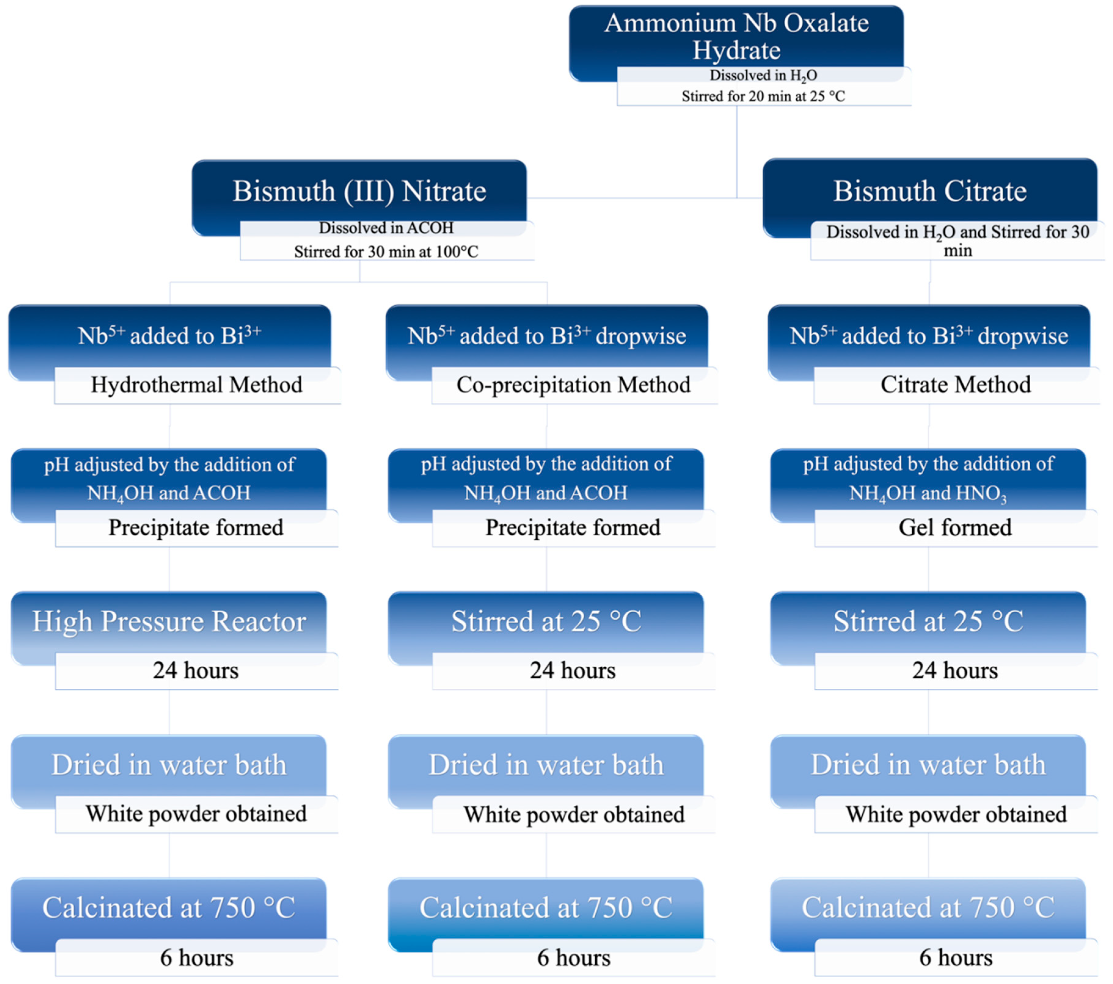
2.2. Preparation of Mixed-Phase BiNbO4 Nanoparticles

2.2.1. Co-precipitation Method

A series of BiNbO4 nanoparticles were prepared by co-precipitation method using bismuth nitrate pentahydrate, and ammonium niobate (V) oxalate hydrate as starting materials, with a stoichiometric proportion of 1:1, Bi(NO3)3·5H2O:C4H4NNbO9·xH2O. In a typical synthesis, 5 g of Bi(NO3)3·5H2O was dissolved in 100 mL 4 M acetic acid under mild heating for complete dissolution (bismuth solution). C4H4NNbO9·xH2O was dissolved in 75 mL deionized water (niobium solution). Bismuth solution was added to the niobium solution, the two solutions were mixed and kept under constant stirring using Witeg MSH-20D speed adjusted at 300 RPM. Then, acetic acid (CH3COOH) or ammonium hydroxide (NH4OH) was used to adjust the pH values to 2, 7, and 10, respectively. The obtained white colloidal solution was left under constant stirring for 24 h followed by evaporating the excess solvent. Finally, the obtained powder was dried, calcined at 750 °C and 900 °C respectively for 6 h. When surfactant was used, it was added to the niobium solution before being added to the bismuth solution at the following mol%: (3% SDS, 10% EG, 10% PEG).

2.2.2. Hydrothermal Method

Same above-mentioned procedure was implemented for synthesis of BiNbO4 using hydrothermal method. However, the colloidal solution was transferred into high-pressure Parr reactor model 4848 equipped with turbine type impellers, speed adjusted at 300 RPM at 220 °C for 24 h. The obtained powder was dried by evaporating the excess solvent and calcined at 750 °C for 6 h.

2.2.3. Citrate Precursor Method

BiNbO4 nanoparticles was prepared by citrate method using bismuth (III) citrate, and ammonium niobate (V) oxalate hydrate as starting materials, with a stoichiometric proportion of 1:1, Bi3+: Nb5+. In a typical synthesis, 5g of bismuth (III) citrate was dissolved in 100 mL deionized water. ammonium niobate (V) oxalate hydrate was dissolved in 75mL deionized water. The two solutions were mixed and kept stirring. Amount of concentrated nitric acid or ammonium hydroxide was used to adjust the pH values to 2, 7, and 10, respectively. The obtained white gel was aged for 24 h followed by evaporating the excess solvent. Finally, the obtained powder was calcined at 750 °C for 6 h. Figure 3 represents detailed synthetic steps for each method used in this study.

2.3. Characterization of the Mixed-Phase BiNbO4

This section provides a detailed investigation of the analytical methods and techniques used to characterize structure and properties of the obtained mixed-phase BiNbO4. Such investigation considers structural, optical, morphological, and elemental analysis of the synthesized BiNbO4.

2.3.1. Powder X-Ray Diffraction (PXRD)

The X-ray diffraction (XRD) of prepared BiNbO4 nanoparticles was investigated using Shimadzu-6100 powder XRD diffractometer equipped with (Cu Kα) radiation tube at (40 kV–30 mA) over the 2θ range of 10°–75° at a rate of 2°/min where λ = 1.542 Å. Figure 4 displays the XRD results for all prepared samples.
The lattice parameters of all prepared BiNbO4 were calculated using Bragg’s law [33] and applying equations (1–10) found in supporting information:
n λ = 2 d sin θ
where n is the order of diffraction (usually n = 1), λ is the X-ray wavelength and d is the spacing between planes of given Miller indices h, k, and l.
The crystalline size was calculated using Scherrer equation [34,35] (2).
B ( 2 θ ) =   K λ L cos θ  
where the peak width B(2θ), at a specific value of (θ being the diffraction angle and λ the X-ray wavelength) is inversely proportional to the crystallite size L. K is a constant; a function of the crystallite geometry generally with a value close to unity. Calculated cell parameters for prepared BiNbO4 are listed in Table 1, Table 2, Table 3, Table 4 and Table 5.
The amount of β-BiNbO4 in a mixed-phase sample was calculated using the intensity of prominent diffraction peaks corresponding to α-BiNbO4 and β-BiNbO4 according to the following equation:
%   β B i N b O 4 = I β B i N b O 4 I β B i N b O 4 + I α B i N b O 4   ×   100
Where I represent the intensity of specific phase present in the sample. The calculated % β-BiNbO4 are listed in Tables S1–S5.

2.3.2. UV-Vis Diffuse Reflectance Spectroscopy (UV-Vis DRS)

Diffused reflectance spectra were obtained using Shimadzu UV-3600 UV-Vis spectrophotometer and recorded in the range from 200 nm to 800 nm. High purity barium sulfate (BaSO4) was used as a standard for baseline correction. The output spectrum shows relation between the intensity of light reflected versus the wavelength. The band gap energies were calculated using the results obtained from the DRS spectra applying Tauc plot method [35]. The band gaps were calculated considering that BiNbO4 is direct semiconductors and using Equation (4).
( α h ν ) 1 n = A ( h ν E g )  
Where α is the absorptivity coefficient, and h ν is the energy of the applied incident light in electron volt, n depends on the nature of transition, for direct allowed transition, the value for n is ½, A is a proportionality [36]. The value of Eg can be estimated by extrapolating the linear fit of a plot of (α ν )1/n vs. (ℎ ν ) as shown in Figure 5. Band gap energies for prepared BiNbO4 are listed in Table 1, Table 2, Table 3, Table 4 and Table 5.

2.3.3. Scanning Electron Microscopy (SEM) and Energy-Dispersive X-Ray Spectroscopy (EDS)

SEM images were obtained from samples applied to carbon tape using a FEI SEM Quanta Inspect S50 Scanning electron microscope operated at an accelerating voltage of 15–30 kV equipped with EDS-Oxford INCA PENTA system for determining the elemental distribution on the surface of the sample.

2.3.4. Specific Surface Area and Porosity

Surface area and porosity were characterized using N2 adsorption at −196.15 °C using a Quantachrome Autosorb-1 volumetric gas sorption instrument. Before measurements, samples were degassed at 200 °C for two hours. Brunauer–Emmett–Teller (BET) theory was used to calculate surface area, pore size distributions were determined by Barett–Joyner–Halenda (BJH) model based on the desorption branch of the N2 isotherms over a selected range of relative pressure P/P0 from 0 to 1. Specific surface area and porosity data are presented in Table 1, Table 2, Table 3, Table 4 and Table 5.

3. Results and Discussion

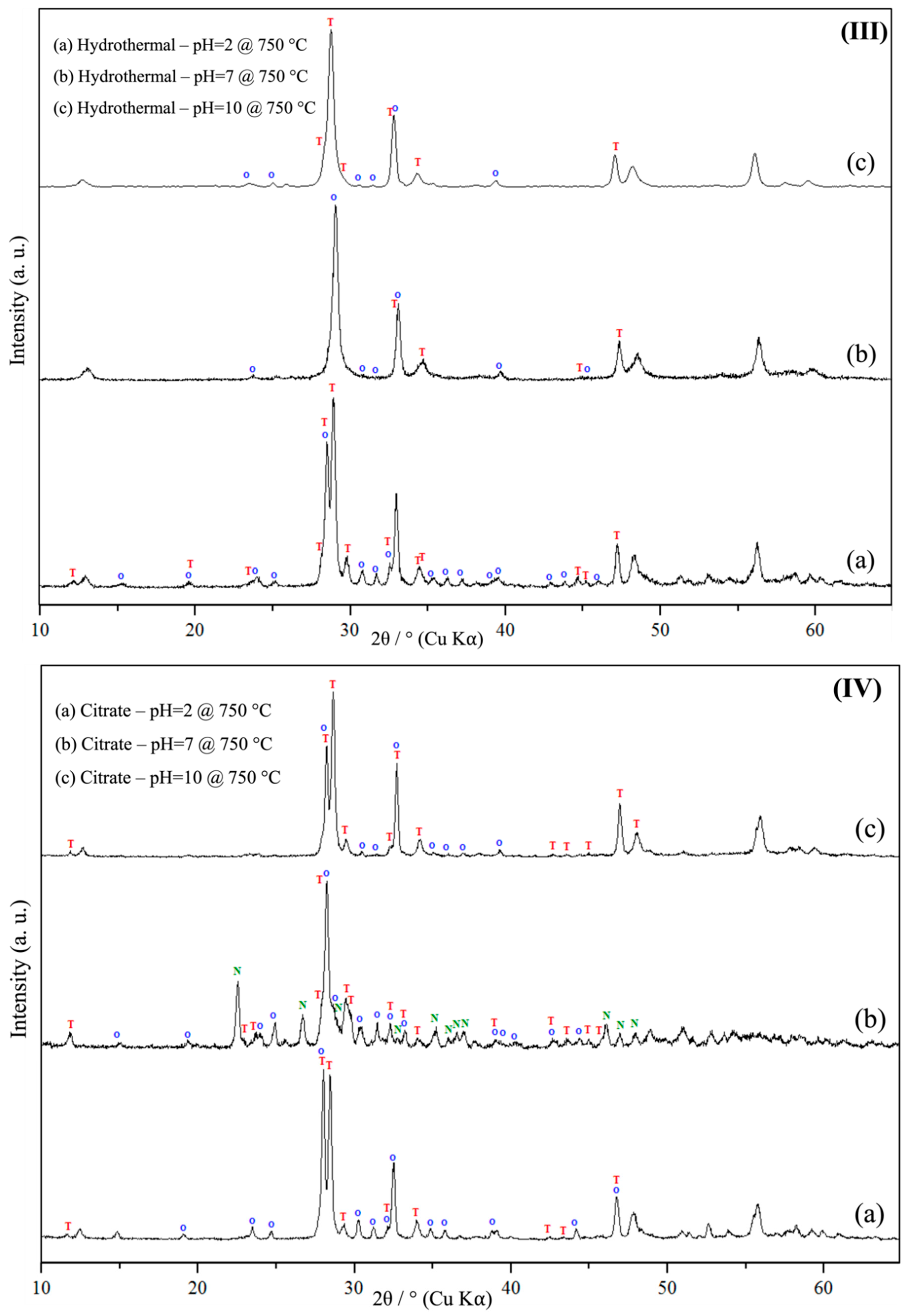
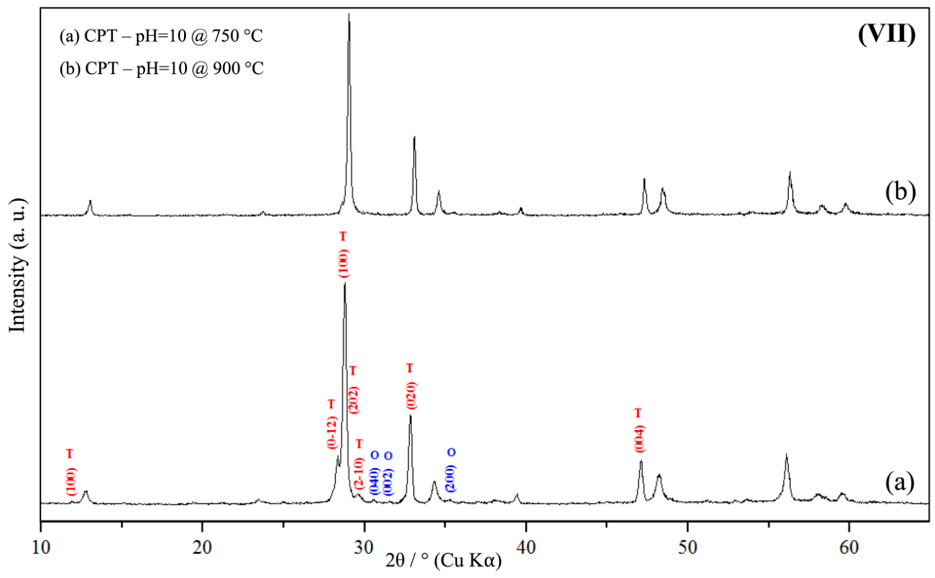
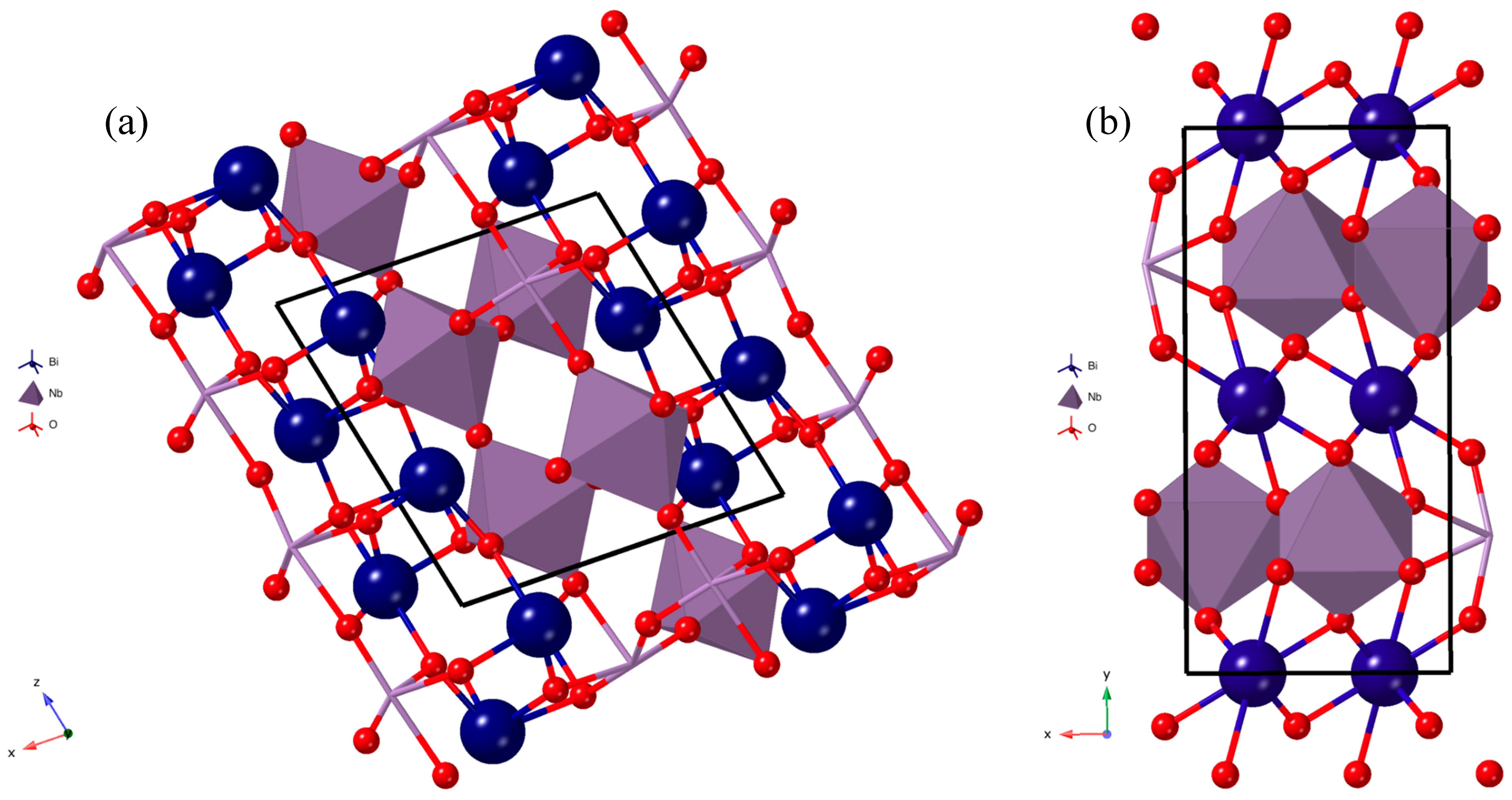
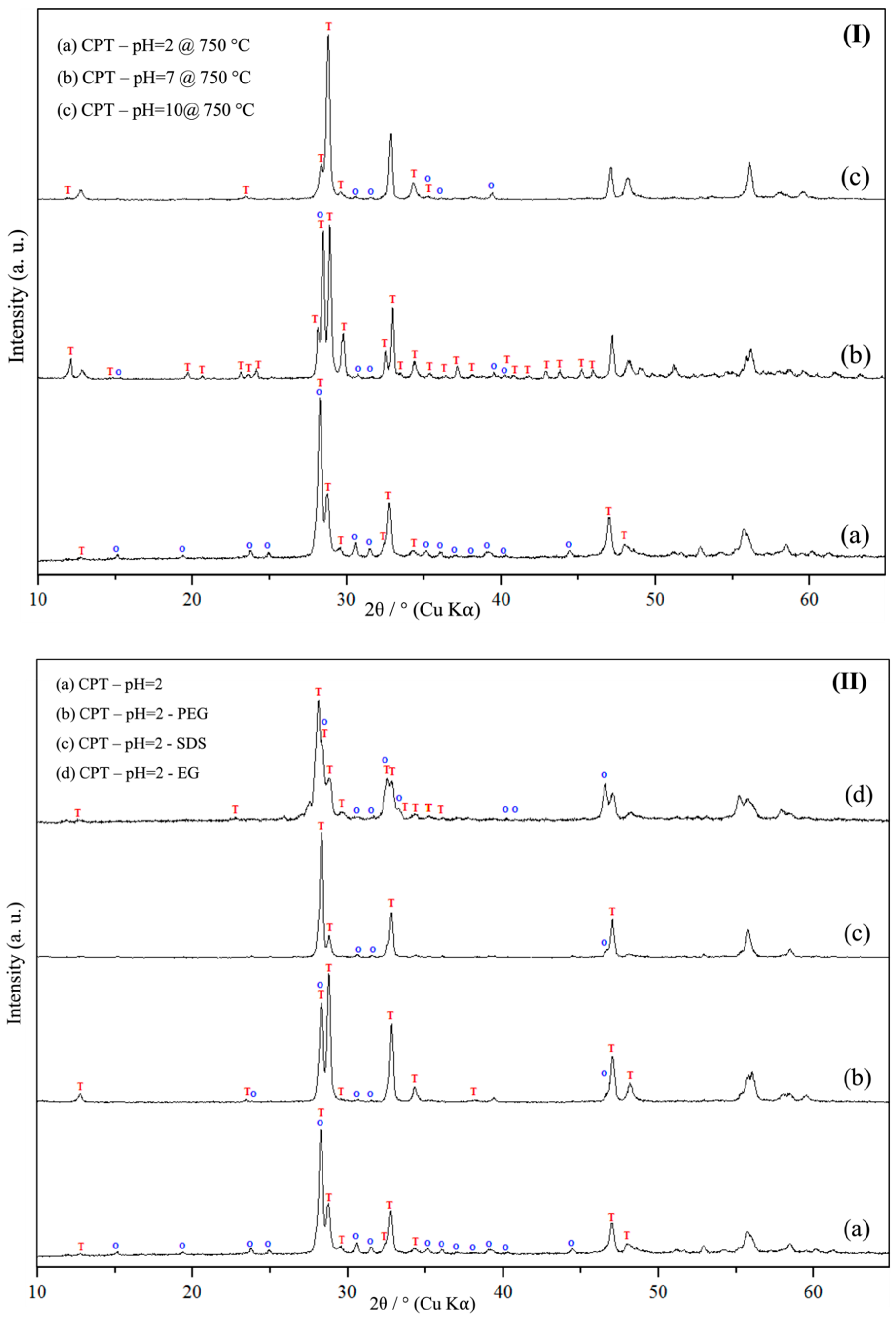
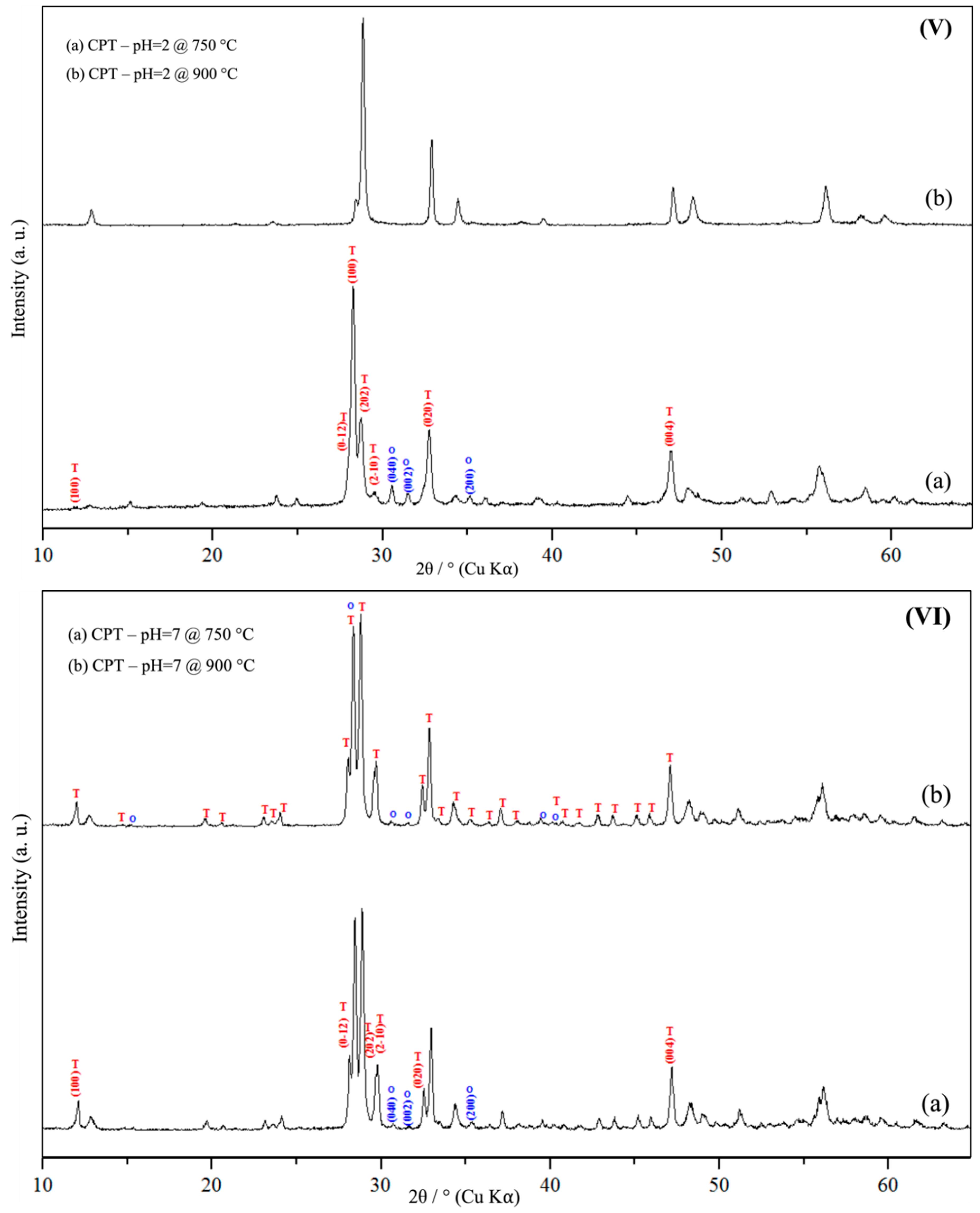
3.1. Powder X-Ray Diffraction Spectroscopy (PXRD)
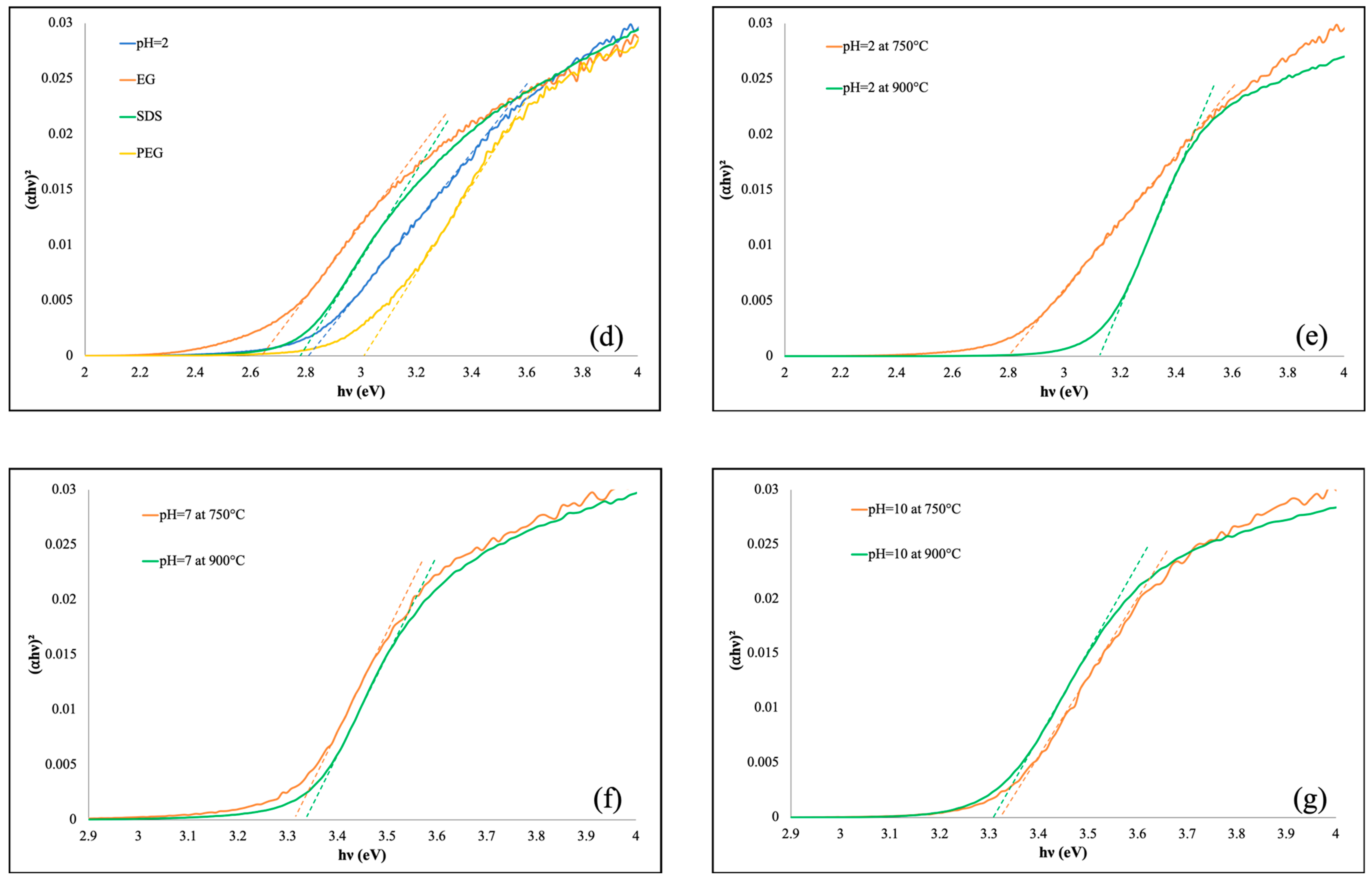
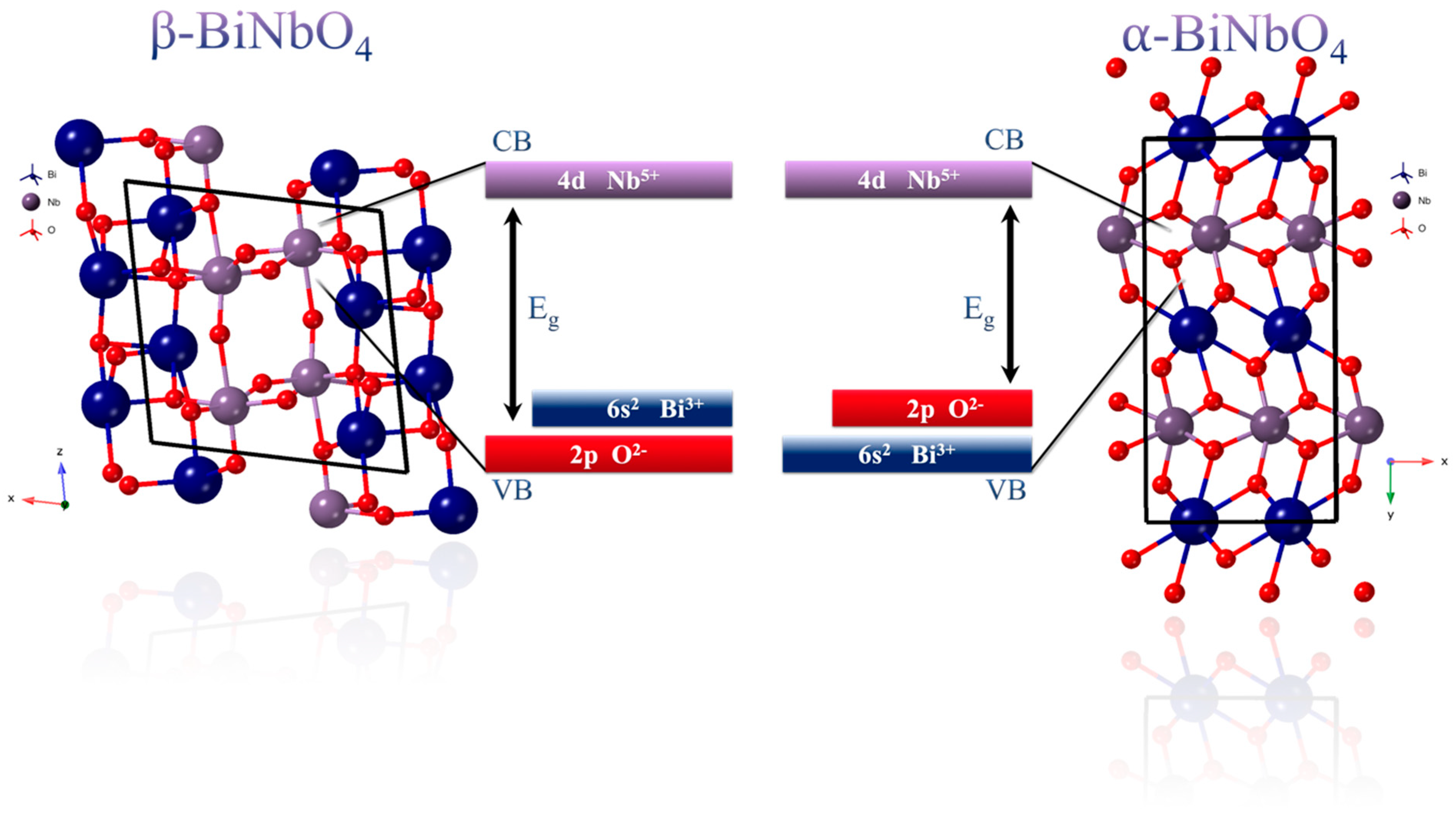
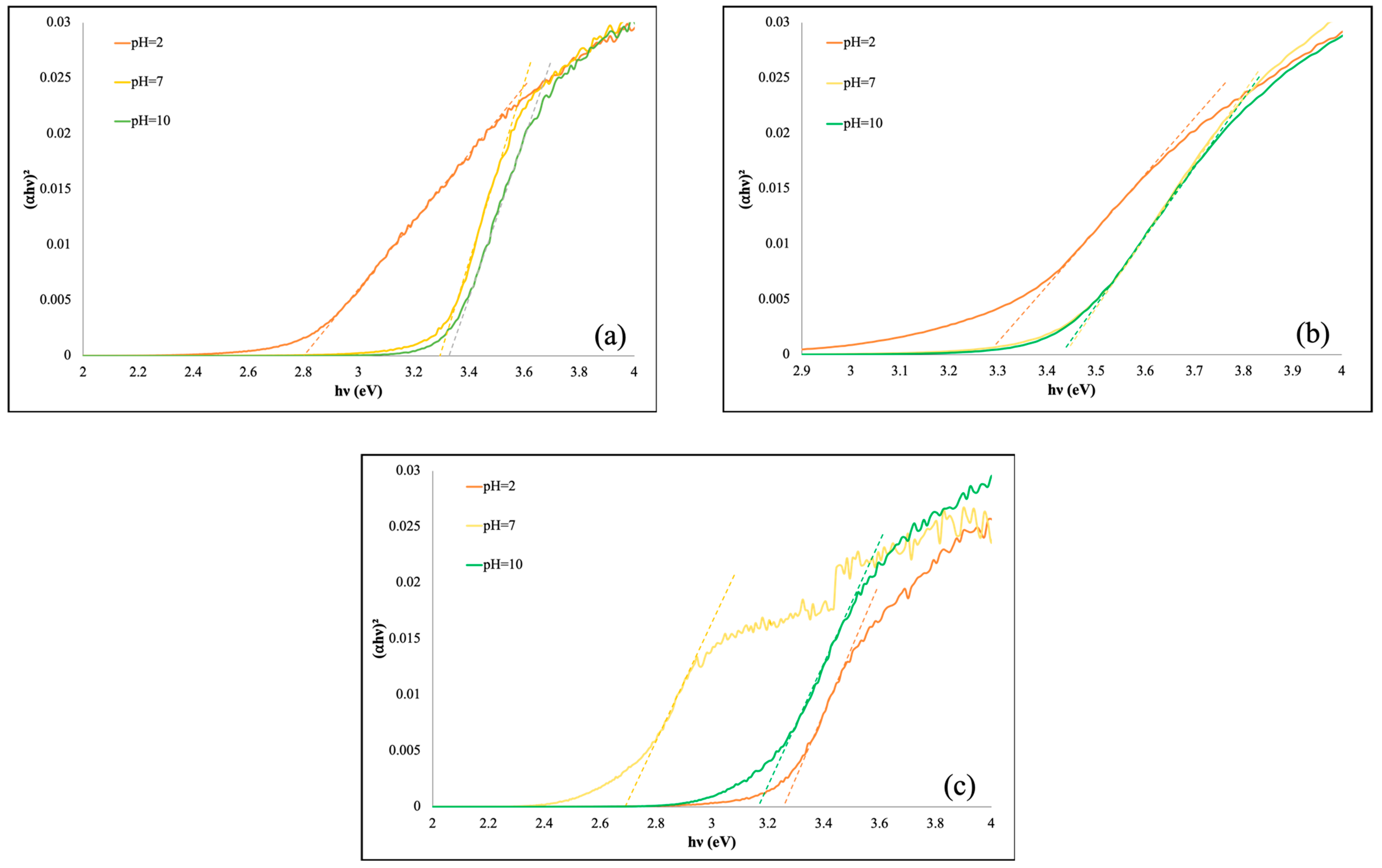
The crystalline phase of BiNbO4 was examined using PXRD. Initially, the XRD pattern of BiNbO4 was analyzed and confirmed based on the standard PXRD database card (ICDD, 2018). Figure 4I shows the XRD pattern of BiNbO4 prepared using co-precipitation method at different pHs and calcined at 750 °C for 6 h. Based on the obtained XRD data, the lattice exhibits α to β phase transformation upon increasing the pH of the solution. The obtained XRD patterns of were correlated with the crystallographic information data base of α- BiNBO4 (PDF-00-016-0295) and β-BiNBO4 (PDF 00-016-0486). Figure 4Ia shows the XRD pattern of BiNbO4 prepared at pH 2, the majority of the XRD peaks including the main peak correspond to (hkl) of (121) plane at 2θ = 28.3 are readily indexed to α-BiNbO4. The calculated cell parameters were: a = 4.99 Å, b = 11.70 Å, c = 5.69 Å, which is in good agreement with literature values reported previously [37].
Figure 4Ib shows the XRD pattern of BiNbO4 prepared at pH 7. At neutral pH, both α- and β-BiNbO4 phase co-exist. Furthermore, based on the intensity ratio of the diffracted peaks, 86.41% of the obtained powder present as β-BiNbO4. It should be noted that the XRD pattern shows a gradual 0.2° shift of the peak towards a higher scattering angle with a net decrease on the part of the lattice parameters and increase in crystalline size as shown in Table 1. The overall effect can be attributed to the change in the phase composition associated with increasing the pH, i.e., increase amount of β-BiNbO4, data reported in Table S1. The decrease in the crystallite size at pH 2 may be attributed to the repulsive interactions between an acid and precursor solution that prevents coalescence of the nanocrystallites and inhibits the particle growth, on the other hand, opposite effect occurs when pH increased by introducing base in the precursor solution enhancing formation of β-BiNbO4 which causes excess compressive stress on the crystalline lattice [38]
Figure 4Ic shows the XRD pattern of the BiNbO4 prepared at pH 10. Based on the pattern obtained, the diffraction peaks of the β-BiNbO4 are more dominant where 75.9% of the obtained powder is present as β-BiNbO4, data reported in Table S1. The pH variation affects the reaction rate by which the intermediate is formed as well the release of gaseous byproducts at the calcination temperature [39]. Such variation revels the existence of tensile stress within the crystallite material as confirmed by the shift appeared in the XRD peaks as well the DRS analyses [40,41].
At this point, it is tempting to say that an increase in the pH results in an increase in β-BiNbO4 formation. Moreover, the powders showed an increase in the crystalline size (Table 1) associated with an increase in the pH. Figure 7a–c show the SEM images of BiNbO4 powder, an agglomerated morphology of the BiNbO4 prepared using co-precipitation method under different pH. Moreover, as indicated from XRD data, the powder showed an increase in the crystalline size with increase in the pH of the precursor solution.
The favored formation of the β-BiNbO4 at high pH can be attributed to the increase crystalline size due to the agglomeration resulting in the preferred β-BiNbO4 formation on the expense of stability of the α-BiNbO4 at high pH. To the best of our knowledge this is the first claim on pH effect on the phase dominance of BiNbO4.
Figure 4III shows the XRD patterns of BiNbO4 prepared using hydrothermal method at pH 2, 7 and 10 and calcined at 750 °C for 6 h. Figure 4IIIa shows the co-existence of both α and β-BiNbO4 for powder prepared at pH 2. Nonetheless, as pH increases the dominant phase becomes the β-BiNbO4 phase as illustrated in Table S2. Moreover, The PXRD pattern of BiNbO4 prepared at pH 2 shows a gradual 0.2° shift of the peak towards a higher scattering angle which can be attributed to the same reasoning discussed above.
Figure 4IV shows the XRD patterns of prepared BiNbO4 using citrate precursor method at pH 2, 7 and 10 and calcined at 750 °C for 6 h. The co-existence of both α and β-BiNbO4 phase is obvious at all pH under study (Table S1) with increase in the amount of β-BiNbO4 at pH 10 observed which is in good agreement with XRD data shown in Figure 4IV. Contrary to the previous observation, the XRD pattern shows a gradual 0.2° shift of the peak towards lower scattering angle indicating a compressive stress of the lattice which could be attributed to incorporating more of the larger size bismuth ions into the lattice structure, this is supported by the increased Bi/Nb ratio (1:1.2) using EDS analysis as shown in Table S19. Moreover, there is an individual niobium oxide present along the obtained products at pH 7, Figure 4IVb. The formation of Nb2O5 is anticipated due to the rapid precipitation in basic solution.
Figure 4II shows the XRD patterns of the prepared BiNbO4 using co-precipitation method at pH 2 and calcined at 750 °C with different surfactant added. Both phases are co-exist however as indicated from XRD, excess of β- phase present when using ethylene glycol (EG) as surfactant, Figure 4II, and Table 4 and Table S4. Based on the results obtained, adding surfactant is of little effect on the phase transformation of BiNbO4.
Figure 4V–VII show the XRD patterns of BiNbO4 prepared using co-precipitation method at pH 2, 7 and 10 and calcined at 750 °C and 900 °C for 6 h. As shown, there is a gradual disappearance of peaks correspond to the α-BiNbO4 upon increasing calcination temperature to 900 °C. Moreover, there is a 0.1° shift in the XRD pattern towards lower scattering angles upon increasing the temperature at pH 7, Figure 4VI. This shift most likely due temperature effect on the crystalline lattice upon increasing the temperature, phase transformation occurs leading to a change in the composition resulted in unit cell expansion i.e., increasing unit cell parameters, data shown in Table 5. The average crystalline size was calculated using Debye–Scherrer equation considering the broadening of the main peak at each case, calculated results are tabulated in Table 1, Table 2, Table 3, Table 4 and Table 5 and Tables S1–S5. The diffraction peaks assigned by the letters O, T and N are correspond to α-BiNbO4, β-BiNbO4 and Nb2O5, respectively. There was some overlap of corresponding peaks from ⍺ and β which was excluded when calculating cell parameters.

3.2. UV-Vis DRS

Table 1, Table 2, Table 3, Table 4 and Table 5 list the calculated band gap energy associated with each prepared nanoparticles. Tauc plot of prepared BiNbO4 using co-precipitation method at pH 2 and calcined at 750 °C is shown in Figure 5a, sample prepared at such condition was found to have the narrowest band gap of 2.8 eV. Nevertheless, nanoparticles prepared at higher pH were found to have relatively larger band gap (>3.2 eV) i.e., capable of harvesting UV light. UV-Vis DRS measurements confirm the dominance of ⍺-BiNbO4 phase at pH 2 whereas β-BiNbO4 dominant at pH 7 and 10 which is in a good agreement with the XRD data discussed above.
BiNbO4 prepared using hydrothermal method at pH 2, Figure 5b, shows the narrowest band gap of 3.26 eV. Therefore, it is tempting to assume that all samples prepared using hydrothermal method can only harvest UV light. Which in agreement with the amount of the β-BiNbO4 present as well as the decrease in the volume observed in each sample as shown in Table S2.
Figure 5c represents band gaps of BiNbO4 prepared using citrate precursor method. The narrowest band gap of 2.69 eV is with dominant α-BiNbO4 present in the mixed-phase powder prepared at pH 7, this was further confirmed by the XRD, Figure 4IV. Whereas, BiNbO4 prepared at pH 2 and 10 show absorbance at lower wavelength i.e., in the UV region of the spectrum.
When ethylene glycol is used as a surfactant, significant shift of absorption band towards the visible region for the photocatalyst prepared at pH = 2 occurred i.e., a red shift of 34.06 nm. On the other hand, when polyethylene glycol (PEG-400) is used as a surfactant, a blue shift of 67 nm in the ban gap energy was observed. Moreover, when using SDS as a surfactant, a red shift of 4.8 nm was observed with the presence of ⍺-BiNbO4 as the dominant phase. Tauc plots are shown in Figure 5d.
Figure 5e–g show Tauc plots for the direct allowed transition of BiNbO4 calcined at 750 °C and 900 °C prepared using co-precipitation method at different pH values. Increasing the calcination temperature from 750 °C to 900 °C caused a significant shift of absorption band towards UV region which reveals the role of temperature on phase transition from α- to β-BiNbO4. Moreover, this observation is further supported using XRD data shown in Figure 4.
The band position of crystalline materials is affected by the crystalline structure, more specifically, the lattice constant. Decreasing lattice constant will decrease the interatomic distance, which in turn, increase the binding energy of the valence electrons to the parent atom. Therefore, more energy is needed to excite the electrons to the conduction band. The crystal structures corresponding to the orthorhombic ⍺-BiNbO4 and the triclinic β-BiNbO4 are represented in Figure 6. The difference between the two crystalline structures is due to the arrangement of (NbO6) polyhedron with respect to the bismuth atoms. In the orthorhombic system, (NbO6) polyhedron alternate with bismuth atoms in a planar manner [42], with a relatively large cell volume, (~330 Å3). Whereas in the triclinic phase, such alternating occur in a distorted manner, and the cell volume is smaller than that of the orthorhombic system (about 324 Å3) [43].
Based on our findings, there is a direct correlation between band gap of prepared BiNbO4 and lattice volume; as the lattice volume increases the band gap decreases. As an example, in Table 1; BiNbO4 prepared under co-precipitation method at pH 2 shows co-existence of both phases with a major orthorhombic phase of ~54.44% in the mixture with lattice volume of 332.1 Å3 which led to a smaller band gap of 2.8. On the other hand, as Table 2 shows when comparing BiNbO4 prepared under hydrothermal method at pH 7 and 10, band gap increased to 3.43 eV with majority of triclinic phase present. The wider band gap can be attributed to the lower crystal volume of 265.64 Å3 and 274.79 Å3, respectively. All discussion above can be applied systematically to all prepared BiNbO4 with consisting trend across the board.

3.3. SEM and Energy-Dispersive X-Ray (EDS) Analysis

SEM images of prepared BiNbO4 are shown in Figure 7. The morphologies of BiNbO4 prepared under co-precipitation method Figure 7a–c show the formation of agglomerated particles. However, BiNbO4 prepared under co-precipitation with surfactants Figure 7d–f, irregular grains were obtained. Moreover, under hydrothermal conditions, BiNbO4 prepared at pH 2, Figure 7g, shows a stretched agglomeration with rough surface and low porosity, nevertheless as the pH increases particles turns into condensed compact structure of agglomeration fine powders. Furthermore, applying citrate precursor method in preparation, agglomeration across all pH values under study is observed. Particles prepared using citrate precursor method (Figure 7j–l) and hydrothermal condition (Figure 7g–i) appeared to be larger than the other preparation conditions under the same magnification. This can be attributed to the presence of severe particle agglomeration.

3.4. N2 Adsorption–Desorption Analysis

Surface area and pore size for all prepared BiNbO4 were investigated using nitrogen adsorption/desorption isotherm. As presented in Table 1, Table 2, Table 3 and Table 4, surface area for hydrothermally prepared samples is the highest when compared to other samples prepared under co-precipitation or citrate precursor conditions. Moreover, prepared BiNbO4 at Ph 2 and 7 using citrate method exhibited lager surface area than those prepared by co-precipitation method. The adsorption–desorption isotherm for the samples is of a type (III) isotherm with observed hysteresis loop range of 0.8–1.0 P/P0. According to the observed data, pore size ranges from 5.6 nm–7.8 nm indicates that all samples possess mesoporous structures. Furthermore, hydrothermally prepared samples showed quite higher pore volume, especially sample prepared at a pH = 7 and 10. Detailed BET adsorption isotherms are listed in Figure S23.

4. Conclusions

In our present study, a combination of orthorhombic α-BiNbO4 and triclinic β-BiNbO4 was always obtained when calcined at a temperature range from 750 °C to 900 °C. PXRD patterns suggest the co-existence of both phases where preferred phase formation is pH and temperature dependent. When co-precipitation method is used, it was observed that pH plays an important role towards the formation of β-BiNbO4 phase, where high pH promotes α- β-BiNbO4 structure, while low pH results in α-BiNbO4 phase. In such a case, BiNbO4 prepared at pH 2 shows the narrowest band gap of 2.86 eV with dominant α-BiNbO4 phase present. Using citrate precursor method, BiNbO4 prepared at pH 7 shows the narrowest band gap of 2.69 eV with dominant α-BiNbO4 phase present, whereas, at acidic or basic conditions wider band gaps >3.0 eV were obtained with dominant β-BiNbO4 phase present. Using hydrothermal approach, BiNbO4 prepared at all pH range of present study show band gap >3.2 eV indicating their absorbance in the UV region. Finally, as temperature increases to 900 °C, a gradual transformation of α- to β is observed. Finally, it can be noticed that as the lattice volume increases, the band gap decreases.

Supplementary Materials

The following are available online at https://www.mdpi.com/2624-8549/1/1/8/s1.

Author Contributions

Conceptualization, M.B.. and S.H.A.; methodology, M.B.; writing—original draft preparation, M.B.; writing—review and editing, A.A.; supervision, A.A.

Funding

This research project was financially supported by the United Arab Emirates University research start-up fund, A.A. (grant No. 31S304).

Conflicts of Interest

The authors declare no conflict of interest.

References

  1. Pahalagedara, M.N.; Pahalagedara, L.R.; Kuo, C.H.; Dharmarathna, S.; Suib, S.L. Ordered mesoporous mixed metal oxides: Remarkable effect of pore size on catalytic activity. Langmuir 2014, 30, 8228–8237. [Google Scholar] [CrossRef] [PubMed]
  2. Yuan, C.; Wu, H.B.; Xie, Y.; Lou, X.W. Mixed transition-metal oxides: Design, synthesis, and energy-related applications. Angew. Chem. Int. Ed. 2014, 53, 1488–1504. [Google Scholar] [CrossRef] [PubMed]
  3. Barmi, M.J.; Minakshi, M. Tuning the Redox Properties of the Nanostructured CoMoO4 Electrode: Effects of Surfactant Content and Synthesis Temperature. ChemPlusChem 2016, 81, 964–977. [Google Scholar] [CrossRef]
  4. Zhou, Y.X.; Yao, H.B.; Zhang, Q.; Gong, J.Y.; Liu, S.J.; Yu, S.H. Hierarchical FeWO4 microcrystals: Solvothermal synthesis and their photocatalytic and magnetic properties. Inorg. Chem. 2009, 48, 1082–1090. [Google Scholar] [CrossRef] [PubMed]
  5. Tan, F.K.; Hassan, J.; Wahab, Z.A.; Azis, R.S. Electrical conductivity and dielectric behaviour of manganese and vanadium mixed oxide prepared by conventional solid state method. Eng. Sci. Technol. Int. J. 2016, 19, 2081–2087. [Google Scholar] [CrossRef] [Green Version]
  6. Arora, A.K.; Jaswal, V.S.; Singh, K.; Singh, R. Applications of metal/mixed metal oxides as photocatalyst: A review. Orient. J. Chem. 2016, 32, 2035–2042. [Google Scholar] [CrossRef]
  7. Gawande, M.B.; Pandey, R.K.; Jayaram, R.V. Role of mixed metal oxides in catalysis science—Versatile applications in organic synthesis. Catal. Sci. Technol. 2012, 2, 1113–1125. [Google Scholar] [CrossRef]
  8. Mao, N.; Jiao, Y. CuAl Hydrotalcite Formed CuAl-Mixed Metal Oxides for Photocatalytic Removal of Rhodamine B and Cr(VI). ChemistrySelect 2018, 3, 12676–12681. [Google Scholar] [CrossRef]
  9. Rodriguez, J.A. Electronic and chemical properties of mixed-metal oxides: Basic principles for the design of DeNOx and DeSOx catalysts. Catal. Today 2003, 85, 177–192. [Google Scholar] [CrossRef]
  10. Cui, H.; Zayat, M.; Levy, D. Sol-gel synthesis of nanoscaled spinels using propylene oxide as a gelation agent. J. Sol-Gel Sci. Technol. 2005, 35, 175–181. [Google Scholar] [CrossRef]
  11. Elia, A.; Aispuro, P.M.; Quaranta, N.; Martín-Martínez, J.M.; Vázquez, P. Synthesis and characterization of new silica-titania mixed oxides obtained by sol-gel technique. Macromol. Symp. 2011, 301, 136–145. [Google Scholar] [CrossRef]
  12. Gawande, M.B.; Branco, P.S.; Parghi, K.; Shrikhande, J.J.; Pandey, R.K.; Ghumman, C.A.A.; Bundaleski, N.; Teodoro, O.M.N.D.; Jayaram, R.V. Synthesis and characterization of versatile MgO-ZrO2 mixed metal oxide nanoparticles and their applications. Catal. Sci. Technol. 2011, 1, 1653–1664. [Google Scholar] [CrossRef]
  13. Sheets, W.C.; Stampler, E.S.; Kabbour, H.; Bertoni, M.I.; Cario, L.; Mason, T.O.; Marks, T.J.; Poeppelmeier, K.R. Facile Synthesis of BiCuOS by Hydrothermal Methods. Inorg. Chem. 2007, 46, 2333–2335. [Google Scholar] [CrossRef]
  14. Zyryanov, V.V. Mechanochemical synthesis and thermal behavior of metastable mixed oxides in the CaO-Sb2O3-Bi2O3 system. Inorg. Mater. 2003, 39, 1163–1171. [Google Scholar] [CrossRef]
  15. Babu, R.; Kelkar, S.; Kashid, V.; Achary, S.N.; Salunke, H.G.; Gupta, N.M. Photophysical, bandstructural, and textural properties of o-FeNbO4 in relation to its cocatalyst-assisted photoactivity for water oxidation. RSC Adv. 2014, 4, 33435–33445. [Google Scholar] [CrossRef]
  16. Rao, K.S.; Buddhudu, S. Structural, Thermal and Dielectric Properties of BiNbO4 Ceramic Powder. Ferroelectr. Lett. Sect. 2010, 37, 101–109. [Google Scholar] [CrossRef]
  17. Dunkle, S.S.; Suslick, K.S. Photodegradation of BiNbO4 Powder during Photocatalytic Reactions. Scanning 2009, 113, 1031–10345. [Google Scholar] [CrossRef]
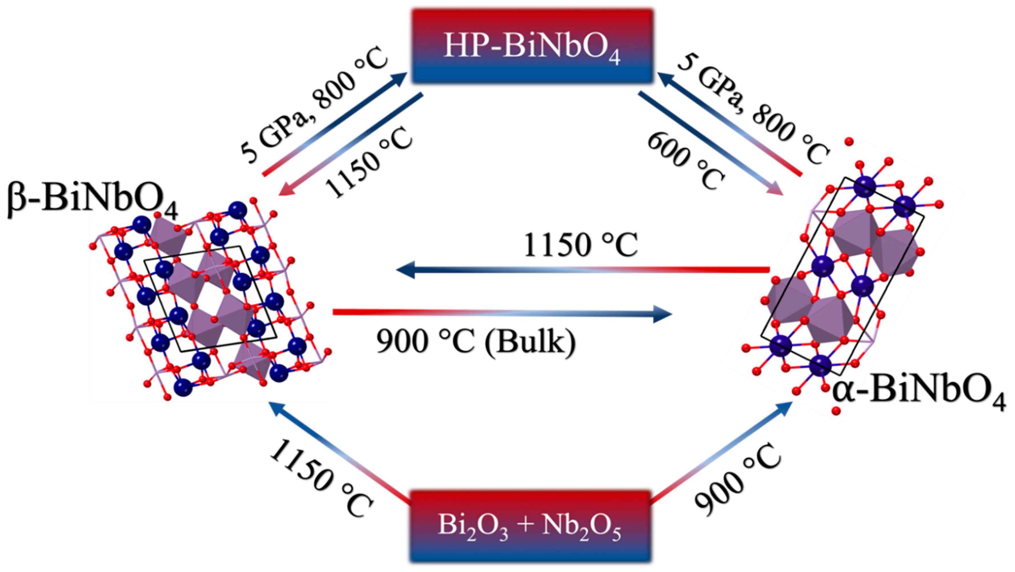
  18. Aurivillius, B. X-ray investigations on BiNbO4, BiTaO4 and BiSbO4. Ark. Kemi. 1951, 3, 153–161. [Google Scholar]
  19. Roth, R.S.; Waring, J.L. Phase equilibrium relations in the binary system bismuth sesquioxide-niobium pentoxide. J. Res. Natl. Bur. Stand. Sect. A Phys. Chem. 1962, 66A, 451. [Google Scholar] [CrossRef]
  20. Diehl, R.; Carpentier, C. The Crystal Structure of Triclinic β-BiNbO4. Acta Crystallogr. 1973, B34, 1105–1111. [Google Scholar]
  21. Popolitov, V.I.; Ivanova, L.A.; Stephanovitch, S.Y.; Chetchkin, V.V.; Lobachev, A.N.; Venevtsev, Y.N. Ferroelectrics ab04: Synthesis of single crystals and ceramics; dielectric and nonlinear optical properties. Ferroelectrics 1974, 8, 519–520. [Google Scholar] [CrossRef]
  22. Subramanian, M.A.; Calabrese, J.C. Crystal Structure of The Low Temperature Form of Bismuth Niobium Oxide [⍺-BiNbO4]. Mater. Res. Bull. 1993, 28, 523–529. [Google Scholar] [CrossRef]
  23. Zhou, D.; Wang, H.; Yao, X.; Wei, X.; Xiang, F.; Pang, L. Phase transformation in BiNbO4 ceramics. Appl. Phys. Lett. 2007, 90, 172910. [Google Scholar] [CrossRef]
  24. Zhai, H.F.; Qian, X.; Kong, J.Z.; Li, A.D.; Gong, Y.P.; Li, H.; Wu, D. Abnormal phase transition in BiNbO4 powders prepared by a citrate method. J. Alloys Compd. 2011, 509, 10230–10233. [Google Scholar] [CrossRef]
  25. Zhai, H.F.; Li, A.D.; Kong, J.Z.; Li, X.F.; Zhao, J.; Guo, B.L.; Yin, J.; Li, Z.S.; Wu, D. Preparation and visible-light photocatalytic properties of BiNbO4 and BiTaO4 by a citrate method. J. Solid State Chem. 2013, 202, 6–14. [Google Scholar] [CrossRef]
  26. Xu, C.; He, D.; Liu, C.; Wang, H.; Zhang, L.; Wang, P.; Yin, S. High pressure and high temperature study the phase transitions of BiNbO4. Solid State Commun. 2013, 156, 21–24. [Google Scholar] [CrossRef]
  27. Zhou, D.; Xu, C.; He, D.W.; Sen Fu, M.; Guo, J.; Zhou, H.F.; Pang, L.X.; Yao, X. Dielectric properties and phase transitions of BiNbO4 ceramic. Scr. Mater. 2014, 81, 40–43. [Google Scholar] [CrossRef]
  28. Liu, Y.; Xu, C.; He, D.; Zhang, J.; Hu, Q.; Qi, L. Exploring the phase transition of BiNbO4: A high pressure x-ray diffraction study. Solid State Commun. 2017, 265, 15–18. [Google Scholar] [CrossRef]
  29. Zou, Z.; Arakawa, H.; Ye, J. Substitution Effect of Ta5+ by Nb5+ on Photocatalytic, Photophysical, and Structural Properties of BiTa1–x NbxO4 (0≦x≦1). J. Mater. Res. 2002, 17, 1446–1454. [Google Scholar] [CrossRef]
  30. Zou, Z.; Ye, J.; Arakawa, H. Photocatalytic water splitting into H2 and/or O2 under UV and visible light irradiation with a semiconductor photocatalyst. Int. J. Hydrog. Energy 2003, 28(6), 663–669. [Google Scholar] [CrossRef]
  31. Zou, Z.; Ye, J.; Arakawa, H. Optical and structural properties of the BiTa1−xNbxO4 (0≦x≦1) compounds. Solid State Commun. 2001, 119, 471–475. [Google Scholar] [CrossRef]
  32. Wiegel, M.; Middel, W.; Blasse, G. Influence of ns2 ions on the luminescence of niobates and tantalates. J. Mater. Chem. 1995, 5, 981–983. [Google Scholar] [CrossRef]
  33. Bragg, W.H.; Bragg, W.L. The reflection of X-rays by crystals. Proc. R. Soc. London. Ser. A Contain. Pap. Math. Phys. Character. 1913, 88, 428–438. [Google Scholar] [CrossRef]
  34. Scherrer, P. Bestimmung der inneren Struktur und der Größe von Kolloidteilchen mittels Röntgenstrahlen. In Kolloidchem. Ein Lehrb; Springer: Berlin/Heidelberg, Germany, 1912; pp. 387–409. [Google Scholar]
  35. Tauc, J. Absorption edge and internal electric fields in amorphous semiconductors. Mater. Res. Bull. 1970, 5, 721–729. [Google Scholar] [CrossRef]
  36. Ting, C.-C.; Chen, S.-Y.; Liu, D.-M. Structural evolution and optical properties of TiO2 thin films prepared by thermal oxidation of sputtered Ti films. J. Appl. Phys. 2000, 88, 4628–4633. [Google Scholar] [CrossRef]
  37. Radha, R.; Gupta, U.N.; Samuel, V.; Muthurajan, H.; Kumar, H.H.; Ravi, V. A co-precipitation technique to prepare BiNbO4 powders. Ceram. Int. 2008, 34, 1565–1567. [Google Scholar] [CrossRef]
  38. Schreiner, W.N. A standard test method for the determination of RIR values by X-ray diffraction. Powder Diffr. 1995, 10, 25–33. [Google Scholar] [CrossRef]
  39. Cullity, B.D. Elements of X-Ray Diffraction; Addison-Wesley publishing Co., Inc.: Boston, MA, USA, 1978. [Google Scholar]
  40. Fluri, A.; Pergolesi, D.; Roddatis, V.; Wokaun, A.; Lippert, T. In situ stress observation in oxide films and how tensile stress influences oxygen ion conduction. Nat. Commun. 2016, 7, 10692. [Google Scholar] [CrossRef] [Green Version]
  41. Khan, M.A.; Yang, J.W.; Simin, G.; Gaska, R.; Shur, M.S.; zur Loye, H.-C.; Tamulaitis, G.; Zukauskas, A.; Smith, D.J.; Chandrasekhar, D. Lattice and energy band engineering in AlInGaN/GaN heterostructures. Appl. Phys. Lett. 2000, 76, 1161–1163. [Google Scholar] [CrossRef]
  42. Lee, C.-Y.; Macquart, R.; Zhou, Q.; Kennedy, B.J. Structural and spectroscopic studies of BiTa1− xNbxO4. J. Solid State Chem. 2003, 174, 310–318. [Google Scholar] [CrossRef]
  43. Maruyama, Y.; Izawa, C.; Watanabe, T. Synthesis of BiNbO4 by the Flux Method. ISRN Mater. Sci. 2012, 2012, 1–5. [Google Scholar] [CrossRef]
Figure 1. Phase change of BiNbO4. Crystal structures reproduced with permission from Ref. [26].
Chemistry 01 00008 g001
Figure 2. Band structures of BiNbO4. Crystal structures reproduced with permission from Ref. [20]. Atom colors: blue: Bi, purple: Nb and red: O.
Chemistry 01 00008 g002
Figure 3. Schematic illustration of the synthetic procedures of BiNbO4.
Chemistry 01 00008 g003
Figure 4. PXRD patterns of BiNbO4: (I) Co-precipitation: (a) pH 2, (b) pH 7, (c) pH 10; (II) pH 2, calcined at 750 °C: (a) no surfactant, (b) polyethylene glycol (PEG), (c) sodium dodecyl sulfate (SDS), (d) ethylene glycol (EG); (III) Hydrothermal: (a) pH 2, (b) pH 7, (c) pH 10; (IV) Citrate precursor: (a) pH 2, (b) pH 7, (c) pH 10; (V) Co-precipitation, calcined at 750 °C and 900 °C at pH 2; (VI) Co-precipitation, calcined at 750 °C and 900 °C at pH 7; (VII) Co-precipitation, calcined at 750 °C and 900 °C at pH = 10. The diffraction peaks assigned by the letters O, T and N are correspond to α-BiNbO4, β-BiNbO4 and Nb2O5, respectively.
Chemistry 01 00008 g004aChemistry 01 00008 g004bChemistry 01 00008 g004cChemistry 01 00008 g004d
Figure 5. Tauc plots of directly allowed transition of BiNbO4: (a) Co-precipitation; (b) Hydrothermal; (c) Citrate method; (d) Co-precipitation at pH 2; (e) Co-precipitation calcined at 750 °C and 900 °C at pH 2; (f) pH 7; and (g) pH 10.
Chemistry 01 00008 g005aChemistry 01 00008 g005b
Figure 6. Crystal structure of (a) β-BiNbO4 and (b) ⍺-BiNbO4. Crystal structures printed with permission from Ref. [20,42]. Atom colors: blue: Bi, purple: Nb and red: O.
Chemistry 01 00008 g006
Figure 7. SEM images of BiNbO4 calcined at 750 °C: (a) Co-precipitation; pH 2, (b) Co-precipitation, pH 7; (c) Co-precipitation, pH 10; (d) Co-precipitation, EG; (e) Co-precipitation, PEG; (f) Co-precipitation, SDS; (g) Hydrothermal, pH 2; (h) Hydrothermal, pH 7; (i) Hydrothermal, pH 10; (j); Citrate precursor, pH 2; (k) Citrate, pH 7; (l) Citrate precursor, pH 10.
Chemistry 01 00008 g007
Table 1. BiNbO4 prepared by co-precipitation method at 750 °C.
Co-Precipitation Method at 750 °C
ConditionBand Gap Energy (eV)SBET (m2g−1)Pore Size (nm)Vpores (10−3 cm3g−1)Crystalline Size (nm)Lattice Constants
SYSa (Å)b (Å)c (Å) α / ° β / ° γ / ° Vol (Å3)
pH = 22.861.07.61.923.1T7.665.547.9190.0978.1186.65327.88
O4.9911.7015.687909090332.10
pH = 73.33.16.14.735.7T7.515.517.9090.1477.0991.93318.53
O4.9611.655.66909090309.25
pH = 103.32.95.74.134.3T7.265.508.0391.9474.0482.61305.58
O4.9711.685.68909090330.04
Table 2. BiNbO4 prepared by hydrothermal approach at 750 °C.
Hydrothermal Approach at 750 °C
ConditionBand Gap Energy (eV)SBET (m2g−1)Pore Size (nm)Vpores (10−3 cm3g−1)Crystalline Size (nm)Lattice Constants
SYSa (Å)b (Å)c (Å) α / ° β / ° γ / ° Vol (Å3)
pH = 23.266.25.99.213.5T7.125.197.4789.8876.3487.53267.62
O4.9411.635.65909090324.60
pH = 73.4312.97.524.323.1T-------
O-------
pH = 103.4320.57.639.121.1T7.285.197.4886.0377.6387.13274.79
O4.9111.815.73909090332.27
Table 3. BiNbO4 prepared by citrate method at 750 °C.
Citrate Method at 750 °C
ConditionBand Gap Energy (eV)SBET (m2g−1)Pore Size (nm)Vpores (10−3 cm3g−1)Crystalline Size (nm)Lattice Constants
SYSa (Å)b (Å)c (Å) α / ° β / ° γ / ° Vol (Å3)
pH = 23.254.67.48.811.8T7.395.207.3590.8678.3986.01275.13
O4.8411.845.74909090328.93
pH = 72.694.57.08.0-T-------
O5.0311.705.64909090331.92
pH = 103.164.67.48.821.8T7.265.177.4489.5977.1486.65271.62
O4.7911.755.73909090322.50
Table 4. BiNbO4 prepared by co-precipitation method at 750 °C with Surfactant.
Co-Precipitation Method at 750 °C with Surfactant
ConditionBand Gap Energy (eV)SBET (m2g−1)Pore Size (nm)Vpores (10−3 cm3g−1)Crystalline Size (nm)Lattice Constants
SYSa (Å)b (Å)c (Å) α / ° β / ° γ / ° Vol (Å3)
pH = 22.801.07.61.923.1T7.665.547.9190.0978.1186.65327.88
O4.9911.705.69909090332.10
SDS2.771.66.32.541.1T7.335.167.4389.7978.5485.4274.45
O4.9511.725.71909090331.26
PEG3.301.25.71.732.9T-------
O4.9211.675.67909090325.19
EG2.60.67.81.218.6T7.635.517.9290.56102.086.34325.29
O4.9711.755.67909090331.49
Table 5. BiNbO4 prepared by co-precipitation method at 900 °C.
Co-Precipitation Method at 900 °C
ConditionBand Gap Energy (eV)Crystalline Size (nm)Lattice Constants
SYSa (Å)b (Å)c (Å) α / ° β / ° γ / ° Vol (Å3)
pH = 23.1343.5T-------
O4.9711.695.67909090329.4
pH = 73.334.3T7.575.527.9190.1277.3387.60322.73
O4.9411.695.67909090327.43
pH = 103.347.7T-------
O-------

