Article

Ellipsoidal Design of Robust Secure Frequency Control in Smart Cities Under Denial-of-Service Cyberattack

by
Hisham Soliman
1,
Ehab Bayoumi
2,* and
Sangkeum Lee
3,*
1
Department of Electrical Power Engineering, Faculty of Engineering, Cairo University, Giza 12613, Egypt
2
Department of Electrical Engineering, Faculty of Engineering and Technology, University of Botswana, Gaborone Private Bag UB0022, Botswana
3
Department of Computer Engineering, Hanbat National University, 125, Dongseo-daero, Yuseong-gu, Daejeon 305-719, Republic of Korea
*
Authors to whom correspondence should be addressed.
Smart Cities 2025, 8(2), 39; https://doi.org/10.3390/smartcities8020039
Submission received: 8 January 2025 / Revised: 13 February 2025 / Accepted: 25 February 2025 / Published: 3 March 2025

Abstract

Highlights

This research develops a frequency control method, robust against parameter uncertainties, for islanded microgrids. The control method can also withstand the impact of cyberattacks and ensure reliable and secure operation.
What are the main findings?
  • The denial-of-service threat is modeled by the Bernoulli stochastic variable.
  • A new sufficient condition is developed to design the controller in terms of linear matrix inequalities.
What is the implication of the main findings?
  • A microgrid frequency norm-bounded model representing parameter uncertainty and cyberattack is developed.
  • Various testing scenarios demonstrate the suggested controller’s efficacy.

Abstract

To meet the requirements of a smart city in supporting a sustainable high-quality lifestyle for people, there is a need for many smart technologies and smart grids. A smart grid integrates electrical and digital technologies, information, and communication. Microgrids (MGs) are the main components of smart grids. The proposed control scheme introduces a robust control mechanism against model uncertainties and is secure against communication cyberattacks. A novel design criterion is formulated as linear matrix inequalities (LMIs) to provide the required state feedback with integral control. In contrast to the conventional H∞ control approach, the suggested tracker offers enhanced disturbance attenuation and a faster response. Different testing scenarios demonstrate the successful performance of the suggested controller.

1. Introduction

1.1. Brief Survey and Motivation

The rising need for electricity has driven the integration of renewable energy sources (RESs), including wind and solar power, into power systems. The increasing utilization of RESs has several advantages, although it also introduces new obstacles, particularly regarding their stable operation in conjunction with traditional generating units [1,2]. A microgrid (MG) is defined as a low-voltage network linked to a distributed energy generation system, loads, and storage devices such as batteries and flywheels. An MG can function in grid-connected and isolated (or islanded) modes [1,2].
Islanded operation enhances the reliability of RES-based systems by enabling independent frequency and voltage regulation [1,3]. However, maintaining a stable frequency within the microgrid is crucial, as it directly depends on the delicate balance between power generation from the RES and the ever-changing load demands. The intermittent nature of renewable energy sources frequently disrupts this equilibrium. In grid-connected mode, the microgrid frequency matches that of the main grid.
Load frequency control (LFC) aims to address this challenge by dynamically adjusting power generation to maintain constant frequency. This involves regulating power output from sources such as fuel cells and diesel generators.
The objective of LFC is to regulate the actual power generated and the management of power exchange across transmission lines within specified constraints to keep the frequency constant. The load frequency varies due to mismatches between the active power produced by renewable energy sources and the load demand. The load frequency should also be maintained against parameter variations and cyberattacks to ensure stability and security for microgrid operation.
Traditional LFC methods, such as droop control, are commonly employed to adjust the frequency of island microgrids [4]. The main merit of droop control is its decentralized structure, i.e., it does not require state information on the global system. However, it results in reference changes, which must be corrected using a secondary-level regulator. An example of non-droop microgrid control is given in [3]. The control of a microgrid (MG), as described in [3,5,6,7], can be categorized as either alternating current (AC-MG), direct current (DC-MG), or hybrid (AC-DC MG). MGs face the following operational challenges: (1) stabilization under load connection and disconnection, known as plug-and-play operation, as described in [3]; (2) nonlinear loads which result in grid harmonic distortion, whose effect must be attenuated, a power quality problem addressed in [8]; (3) rejection of negative-sequence voltages/currents due to unbalanced loads, as depicted in [9]; and (4) MG control under cyberattacks [10].
Variations in the actual system frequency are caused by parametric uncertainties, system nonlinearities, unpredictable load demand, and the stochastic and intermittent nature of renewable energy sources [1]. In the worst circumstances, these variations may result in system instability and shutdown. Consequently, it is necessary to restore the frequency to its desired value via a secondary controller. This problem is called LFC, or frequency control in short. Control signals are transmitted to the regulated energy sources, such as fuel cells (FCs) and diesel generators (DeGs). The control signals from the secondary controllers in the linked microgrid designs are disseminated among them via communication channels. In modern industry, physical plants are controlled through a communication network known as a cyber-physical system (CPS), unlike conventional control systems. The communication lines are often open and, thus, susceptible to the threat of cyberattacks. Cyberattack threats, including time delays, data manipulation, and denial-of-service attacks, can severely damage the communication networks essential for effective LFC [11].
The following are examples of cyberattacks: (1) time delay attack (TDA); (2) false data injection (FDI), also known as a deception attack; (3) denial of service (DoS), which causes communication congestion and consequently prevents the delivery of measurement or control signals; and (4) replay attacks, in which legitimate data transfer is deliberately or fraudulently duplicated or delayed. The two main types of cyberattacks from a control security viewpoint are DoS and FDI attacks; the former is shown in Figure 1.
A comprehensive analysis of the vulnerabilities of cyber-physical systems to diverse cyberattacks and associated issues is presented in [12]. For example, the power infrastructure in Ukraine saw a DoS assault in 2016 [13], resulting in power outages nationwide. Furthermore, a nuclear power facility in Iran was compromised by the Stuxnet virus, inflicting loss on 60% of the systems [14]. Consequently, it is essential to ensure the stability and security of microgrids against cyberattacks.
The literature highlights several recent advancements in LFC strategies designed to mitigate the impact of cyberattacks:
  • Event-triggered control has been employed to reduce communication network burden and enhance resilience against stealthy attacks [15,16].
  • FDI attacks have been extensively studied, including the development of attack models and analysis of their impact on microgrid stability [17].
  • Robust control techniques such as H control have been investigated to improve system robustness against FDI and DoS attacks in multi-area systems [18].
  • Sampled-data systems have been considered, with controllers designed to address the effects of sampling, time delays, and demand response [19].
  • Distributed event-triggered control has been proposed to mitigate the consequences of FDI attacks in secondary frequency control systems [20].
  • Attack detection and identification have been addressed by the development of observers capable of detecting attacks within the system [21].
  • Time-varying delays have been tackled by implementing decentralized limited bandwidth event-triggered LFC in multi-area power systems [22].
  • Sliding mode control has been utilized in conjunction with event-triggering mechanisms to enhance resilience against periodic DoS attacks in multi-area systems [23].
These studies demonstrate a growing focus on developing LFC strategies that are secure from various cyberattacks, including FDI, DoS, and time delays. By incorporating advanced control techniques and utilizing communication efficiently, researchers are working towards improving the security and reliability of microgrids in the face of increasing cyber threats.

1.2. Paper Contribution

This research focuses on developing robust LFC strategies for islanded microgrids that can withstand the impact of DoS cyberattacks to ensure reliable and secure operation. The DoS attack is modeled as an external disturbance whose effect has to be attenuated. The objective of control is to attract the system’s state to an invariant set (ellipsoid, centered origin) and maintain the states inside it. Reducing the volume of the invariant ellipsoid guarantees the system’s stability and mitigates the effects of disturbances.
The significant contributions of this study are as follows:
  • The invariant ellipsoid technique is employed to enhance robustness against system uncertainties and ensure security against DoS cyberattacks.
  • The development of robust and secure invariant-set control is based on quadratic boundedness of uncertainties in the state-input and disturbances matrices.

1.3. Paper Organization

The subsequent outline presents the structure of the paper: Section 2 presents the MG modeling and problem formulation. In Section 3, the ellipsoidal design of control is introduced. The MG frequency response under system uncertainty and DoS attack is depicted in Section 4. The conclusions are given at the end.
All notation used follow standard conventions: scalars are represented by lowercase Greek letters, vectors by lowercase Latin letters, and matrices by uppercase Latin letters. The symbol (.)’ indicates transposition for matrices or vectors. If X > 0 (≥0) for symmetric matrices, then X is positive definite (non-negative definite). R denotes the sets of real numbers. To simplify the notation of partitioned symmetric matrices, the symbol (*) is used to generically indicate symmetric blocks, whereas trace (X) indicates the trace function of X for square matrices. In the following, the listed mathematical inequalities are used.
  • Fact 1—Bounding Inequality [24]:
For any real matrices X 1 , X 2 , and X 3 of appropriate dimensions, with X 3 X 3 I, the following holds:
X 1   X 3   X 2 + ε X 1 X 1 + ε 1 X 2 X 2 , s c a l a r   ε > 0
  • Fact 2—Schur Complement [24]:
Given a matrix X composed of constant matrices X 1 , X 2 ,   a n d   X 3 , where X 1 = X 1 and 0 < X 2 = X 2 ,
X = X 1 X 3 X 2 ,
we obtain the following result: X > 0 if and only if
X 2 > 0 , X 1 X 3 X 2 1 X 3 > 0 .

2. Renewable Microgrid Modeling and Problem Formulation

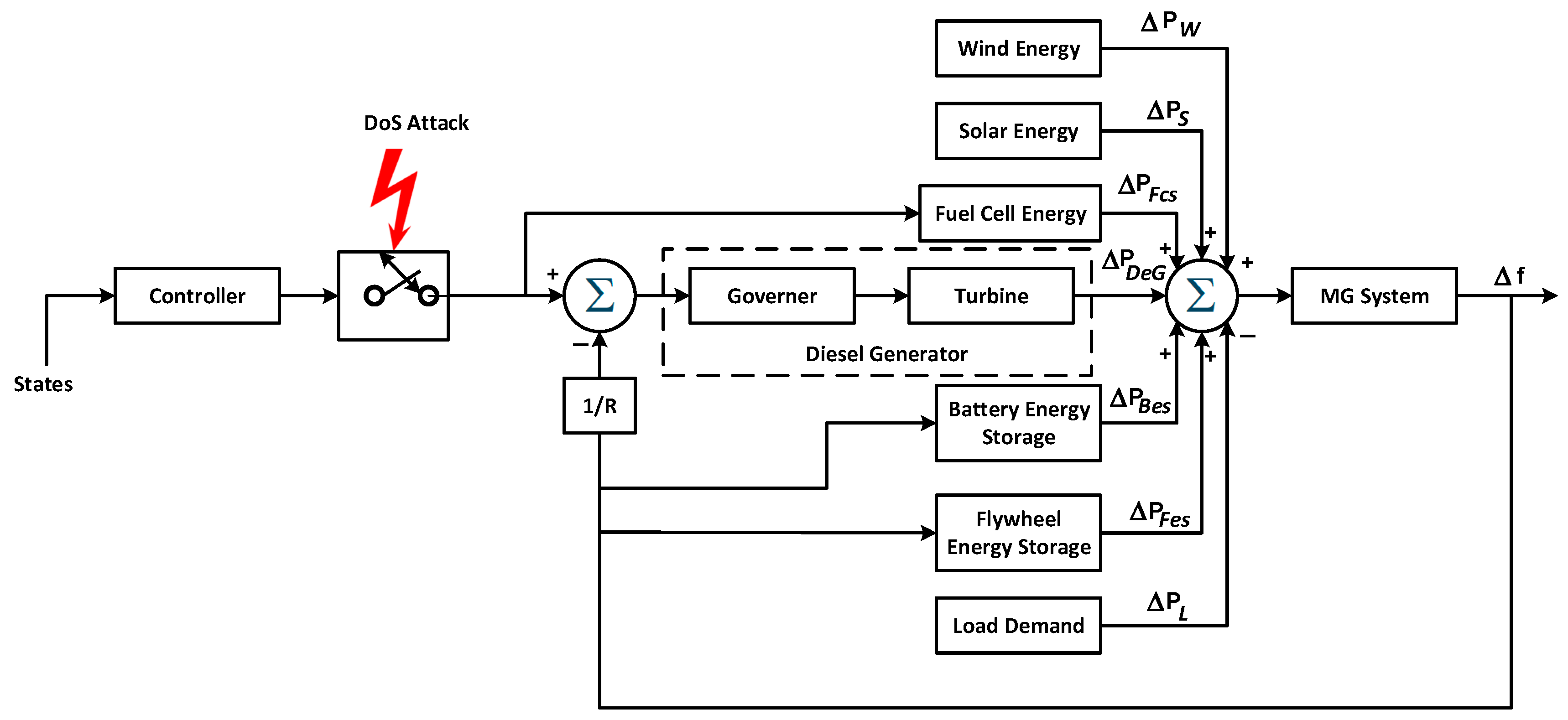
2.1. MG Continuous-Time Model

The block diagram of the microgrid in question is shown in Figure 2. This microgrid acts independently since it is not connected to the main grid. It is made up of a diesel generator, a fuel cell, a storage unit of batteries, a flywheel storage unit, a wind power generation unit, and a solar power generation unit [1]. The microgrid’s diesel generator and fuel cell receive the controller’s output. It is assumed that the generators of renewable energy are running at maximum efficiency. Therefore, the only controllable power-producing equipment includes the diesel generator unit and fuel cell unit. The continuous-time state-space model, linearized around an operating point, of the microgrid shown in Figure 2 is given as follows:
x ˙ = A c x + B c u + D c w , y = C x , z = C x
where x t R n , u t R m , w t R p , y t R l , a n d z t R l are the state, control, external disturbance, output for feedback, and controlled output vectors, respectively. For the MG under consideration, n = 9, m = 2, p = 3, and l = 1. A detailed description of the study MG model and definitions of the variables are given in [25], where x 1 = f , z = f ,
A c = D 2 H 0.0 1 2 H 0.0 1 2 H 0.0 0.0 1 2 H 1 2 H 0.0 1 T i n v 0.0 0.0 0.0 0.0 0.0 0.0 0.0 0.0 1 T f i l t 1 T f i l t 0.0 0.0 0.0 0.0 0.0 0.0 1 R T g 0.0 0.0 1 T g 0.0 0.0 0.0 0.0 0.0 0.0 0.0 0.0 1 T t 1 T t 0.0 0.0 0.0 0.0 1 R f c 0.0 0.0 0.0 0.0 1 T f c 0.0 0.0 0.0 0.0 0.0 0.0 0.0 0.0 1 T i n v 1 T i n v 0.0 0.0 0.0 0.0 0.0 0.0 0.0 0.0 1 T f i l t 1 T f i l t 0.0 1 T b 0.0 0.0 0.0 0.0 0.0 0.0 0.0 1 T b ,
B c = 0 0 0 0 0 0 1 T g 0 0 0 0 1 T f c 0 0 0 0 0 0 , D c = 1 2 H 1 2 H 0 0 0 1 T i n v 0 0 0 0 0 0 0 0 0 0 0 0 0 0 0 0 0 0 0 0 0 ,       C = 1 0 0 0 0 0 0 0 0 .
The study system parameters are given in Table 1.
Symbol definitions for Table 1 are provided in the Abbreviations section at the end of this paper.

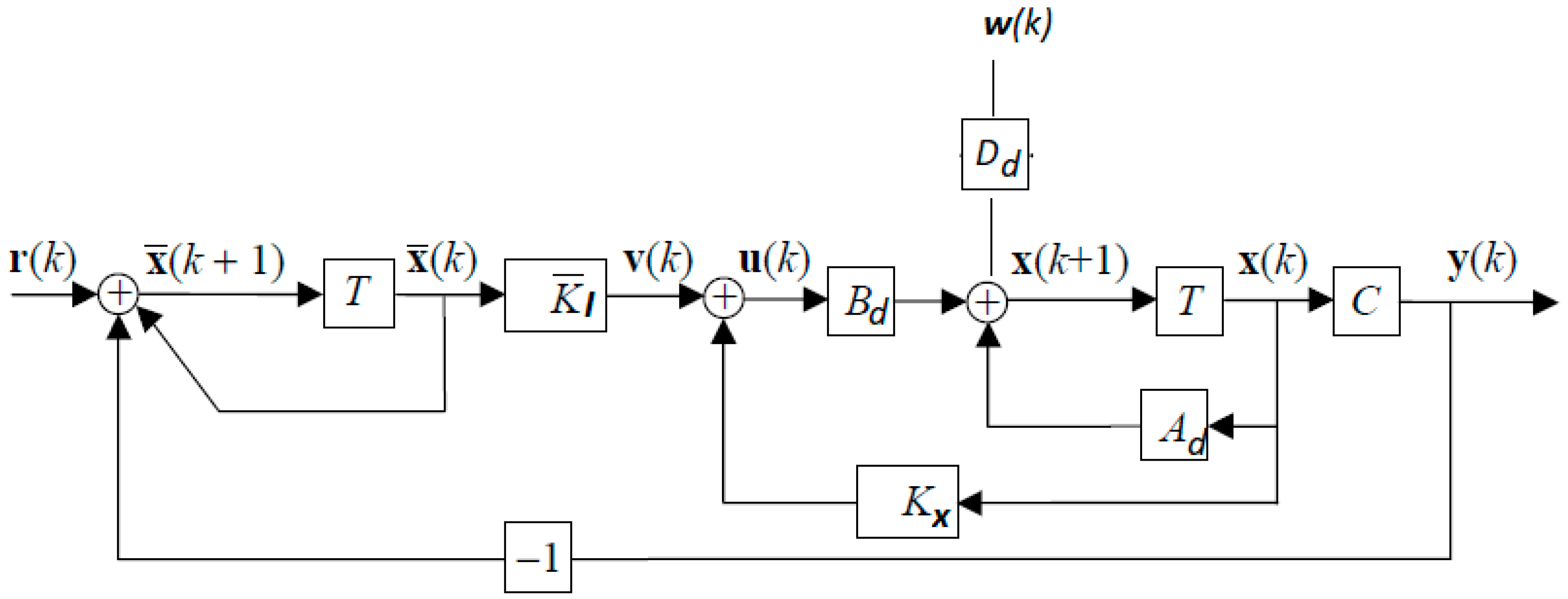
2.2. MG Discrete-Time Model

Since digital computers are employed to control modern industry, a discrete-time model is required. The sampling time for Equation (1) was selected to be nearly one-tenth of the time constant of the fastest pole of Equation (1). By selecting a sampling time T s = 0.01   s , the discrete-time model for Equation (1) becomes the following:
x k + 1 = A d x k + B d u k + D d w k , y k = C x k = z ( k ) }
Since the study system is type 0, it has steady-state errors, f ( ) 0 , for a step input. To eliminate these errors, the system type must be increased by incorporating integral control. Figure 3 shows the addition of a new state for each control error that is integrated.
The resulting state-space equations are as follows:
x k + 1 = A d x k + B d u k + D d w k , y k = C x ( k ) x ¯ ( k + 1 ) = x ¯ ( k ) + r ( k ) y ( k ) u ( k ) = K x x ( k ) + K I x ¯ ( k ) }
Note that the reference r k = f r e f = 0 , and the state estimation vector x ¯ is lx1. The state equations can be combined and rewritten as an augmented state vector x a k = x k , x ¯ k , as shown in Figure 3, as follows:
x k + 1 x ¯ k + 1 = A d 0 C I l x k x ¯ k + B d 0 K x K I x k x ¯ k + D d 0 w ( k ) + 0 I l r k y k = C 0 x k x ¯ k }
or
x a k + 1 = A x a k + B u k + D w k + 0 I l r k , u k = K x a k , y k = C a x a k }
where
A = A d 0 C I l , B = B d 0 , K = K x K I , D = D d 0 , C a = C 0

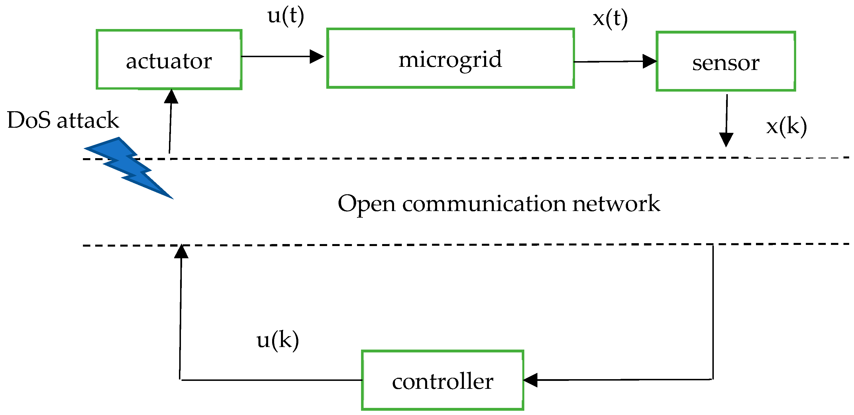
2.3. MG Uncertain Stochastic Discrete-Time Model Under DoS Attack

Either the Markov model or the Bernoulli model could be used the MG stochastic model [26]. The Bernoulli-distributed white sequences β k were selected to model the DoS cyberattacks. With the addition of parameter uncertainty, System (5) becomes the following:
x a k + 1 = A + A x a k + β k B u k + D + D w k
The discrete probability distribution of a random variable that takes the value 0 with probability q = 1 − p and the value 1 with probability p is known as the Bernoulli distribution. In other words, β ( k ) switches between two values, 0 and 1.
The problem is to design a robust, secure state-feedback with integral control,
u ( k ) = K x a ( k ) ,
to stabilize the uncertain system under DoS attack (Equation (6)).

3. Ellipsoidal Design of Secure MG Control

3.1. The Proposed Control

Given an LTI uncertain system:
x a k + 1 = A + A x a k + B + B u k + D + D w k , y ( k ) = C a x a ( k )
The main idea of the ellipsoidal control design is to force the state trajectory x(k) to be attracted into a small region around the origin (ellipsoid, centered the origin):
E = x a k P 1 x a k 1 , P > 0
As time progresses, xa(k) will remain in E when the state trajectory reaches the ellipsoid (time-invariant ellipsoid). Hence, the ellipsoid E is termed attractive or invariant. It is necessary to reduce the ellipsoid volume in terms of the linear function trace (P) in order to attenuate the effect of the external disturbance on the system performance. This problem is solved by the following theorem.
Theorem 1
[27]. Consider the following minimization problem:
m i n i m i z e   t r C a P C a
subject to the following constraints
α P A P + B Y 0 P H A H B Y 0 Ψ D 0 0 0 1 α I 0 0 H D ε 1 I 0 0 ε 2 I 0 ε 3 I 0 ,
P > 0 ,
a n d   t h e   s c a l a r s   0 < α < 1 , ε 1 > 0 , ε 2 > 0 , ε 3 > 0
where
Ψ = P + ε 1 F A F A + ε 2 F B F B + ε 3 F D F D
The minimization is carried out with respect to the matrix variables P = P ; the scalar variables ε 1 , ε 2 , a n d ε 3 ; and the scalar parameter α. The solution P ^ , Y ^ of this problem defines the matrix C a P C a of the output bounding ellipsoid and the state regulator:
K ^ = Y ^ P ^ 1
In the MG control under consideration, the DoS attack β ( k ) switches between two values, 0 and 1, and is multiplied by the input matrix B. Therefore, the input matrix B under the DoS attack switches between two values, 0   a n d   B . Therefore, B = B . d i a g β 1 β m = B . B . I . Comparing these terms with the general form, B = F B B H B , gives F B = B , H B = I . Hence, System (8) can be modified in the norm-bounded form as follows:
x a k + 1 = A + A x a k + ( B + B ) u k + D + D w k
where A = F A A H A   , B = F B B H B ,   D = F D D H D   w i t h   F B = B , H B = I , and A 1 , B 1 , D 1 .
Note that the uncertainty B in Equation (10) is also modeled in the norm-bounded form.
It is worth mentioning that Theorem 1 [27] tackles the regulator problem (constant reference) and ignores the DoS attack. The work of [27] is extended in the following theorem to address the DoS attack and the tracking problem (time-varying reference). Additionally, as previously mentioned, the DoS attack depicts the changes in the input matrix as jumps between matrices B and 0.
The above problem can be solved using the following theorem.
Theorem 2.
Consider the following minimization problem:
m i n i m i z e   t r C a P C a
subject to the following constraints
α P A P + B Y 0 P H A Y 0 Ψ D 0 0 0 1 α I 0 0 H D ε 1 I 0 0 ε 2 I 0 ε 3 I 0 ,
P > 0 ,
a n d   t h e   s c a l a r s   0 < α < 1 , ε 1 > 0 , ε 2 > 0 , ε 3 > 0
where
Ψ = P + ε 1 F A F A + ε 2 B B + ε 3 F D F D
The minimization is carried out with respect to the matrix variables P = P ; the scalar variables ε 1 , ε 2 , a n d   ε 3 ; and the scalar parameter α. The solution P ^ , Y ^ of this problem defines the matrix C a P ^ C a of the output bounding ellipsoid and the state regulator:
K ^ = Y ^ P ^ 1
Proof Sketch of Theorem 2:
See Appendix A. □
Using the numerical values in Table 1 and assuming ±30% uncertainty in H, the average model of the augmented system among such extremities is given as follows:
A = 0.9959 0.0070 0.0583 0.0008 0.0650 0.0006 0.0070 0.0583 0.0626 0 0 0.7788 0 0 0 0 0 0 0 0 0 0.1947 0.7788 0 0 0 0 0 0 0 0.0391 0.0001 0.0012 0.8825 0.0013 0 0.0001 0.0012 0.0013 0 0.00050 0 0 0.0232 0.9753 0 0 0 0 0 0.0126 0 0.0004 0 0.0004 0.9623 0 0.0004 0.0004 0 0.0015 0 0 0 0 0.2168 0.7788 0 0 0 0.0001 0 0 0 0 0.0261 0.1947 0.7788 0 0 0.0950 0.0003 0.0029 0 0.0032 0 0.0003 0.0029 0.9018 0 1.0000 0 0 0 0 0 0 0 0 1.0000
The deviation A = F A H A is obtained using the singular value decomposition as follows [28]:
F A = 0.2279 0 0 0.0049 0 0.0012 0 0 0.0012 0
H A = 0.0055 00.0092 0.0766 0.0011 0.0856 0.0009 0.0092 0.0766 0.0823 0
Similarly, the external disturbance is given as follows:
D = 0.0659 0.0659 0 0 0 0.2500 0 0 0 0 0 0 0 0 0 0 0 0 0 0 0 0 0 0 0 0 0 0 0 0
F D = 0.1990 0 0 0 0 0 0 0 0 0
H D = 0.0055 0.0092 0.00766 0.0011 0.0856 0.0009 0.0092 0.0766 0.0823 0
B = 4.297 e 05 7.7116 e 06 0 0 0 0 0.1175 6.4066 e 08 00.0014868 2.7021 e 10 1.3772 e 07 0.037731 6.6498 e 09 0.0043735 2.7021 e 10 0.00035065 1.0611 e 06 1.544 e 07 0 0
The proposed secure control was obtained by solving Theorem 2 using the MATLAB 2023b LMI control toolbox [29], yalmip interface [30,31], and sedumi solvers [32,33,34], as follows:
K x = 0.36315 0.00290740 0.019315 5.493 0.19187 0.00047615 0.002435 0.019136 0.023224 0.061608 8.5495 e 05 0.0027926 1.9613 e 05 0.0031388 2.764 0.42876 0.051835 0.002918
K i = 0.045952 0.0038624

3.2. Comparison with H Control

The H control can be obtained as follows:
m i n i m i z e   γ
subject to
P A P B Y D 0 P 0 P C γ I 0 γ I > 0 , P > 0 , γ > 0
The resulting controller is K = YP1.
γ o p t = 0.19652
K x = 13668 136.36 933.92 20.575 1068 11.894 135.64 933.68 1019 3365 24.755 521.95 5.7682 482.47 30.003 26.66 521.31 498.08
K i = 0.065488 0.18521

4. Results and Discussion

The microgrid’s LFC performance was assessed using the MATLAB 2023b package. The results are shown in Figure 4, and the microgrid details given in [25] were used for simulation. The model with the proposed controller was evaluated during normal operation and under DoS attack. The microgrid’s load frequency control system with the proposed tracker was assessed under three distinct scenarios during the DoS attack, including deterministic and stochastic disturbances. In each scenario, a DoS attack was generated using a Bernoulli stochastic variable with a probability of 0.8. The DoS attack timing is given in Table 2. For each scenario, we compared the proposed tracker’s performance to that of the H controller to see how well it performs.

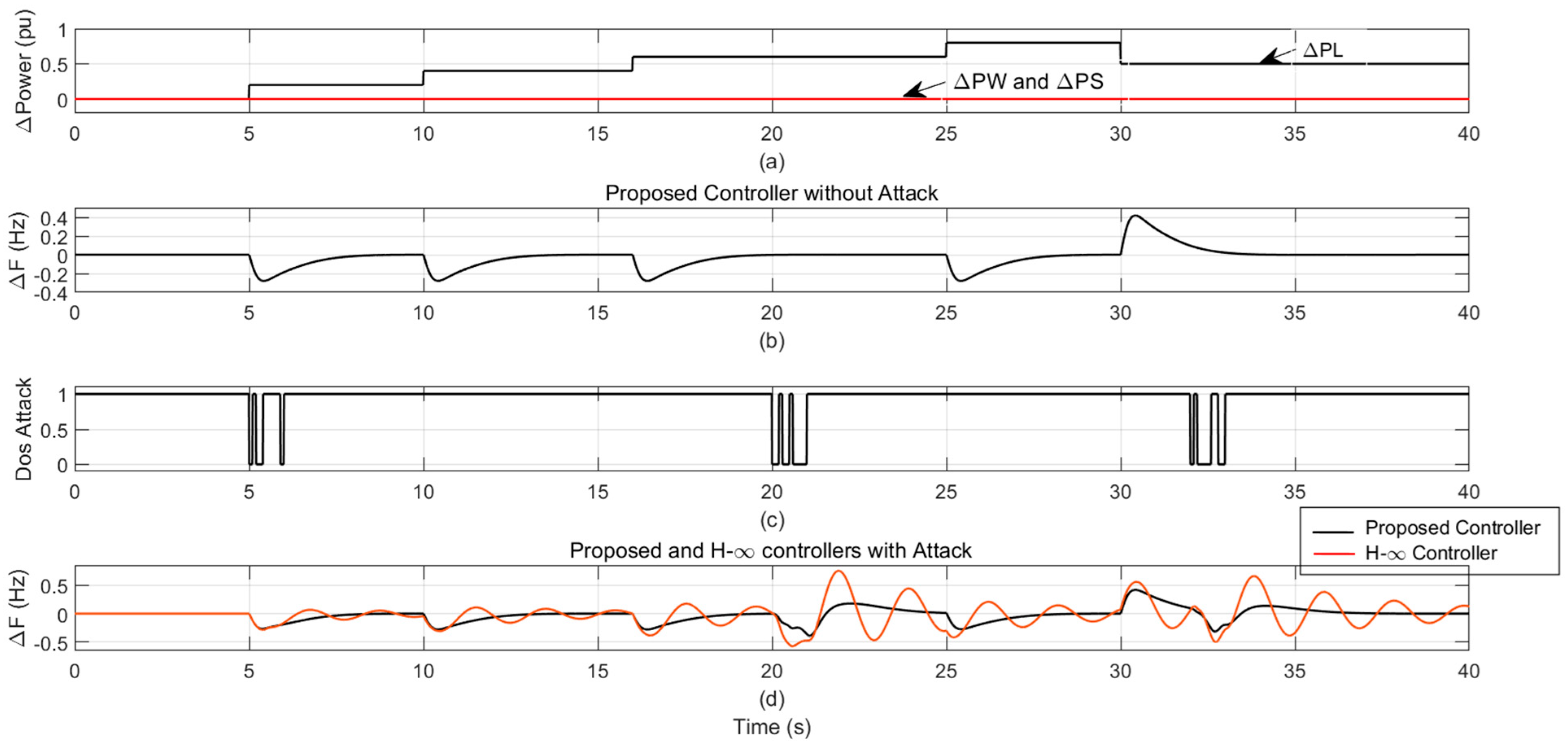
4.1. Scenario 1: Deterministic Disturbance with and Without DoS Attack

4.1.1. Case 1: Multiple Disturbance Steps in Load Power

A multi-step load disturbance with random occurrences at 5, 10, 15, 16, 25, and 30 s was examined, as shown in Figure 4a. The MG frequency change response without an attack under such load patterns is depicted in Figure 4b. Figure 4c illustrates the timing of the DoS attack. Figure 4d illustrates the MG frequency change response using the proposed tracker and the H controller under the above load pattern and DoS attack. Under a step load increase and DoS attack at t = 5 s, the enhanced performance using the proposed tracker is evident, as it outperformed the H controller. The successive up-and-down load step changes, coupled with DoS attack, demonstrate the superiority of the suggested method over the H controller in terms of percentage overshoot, settling time, rise time, and steady-state error.

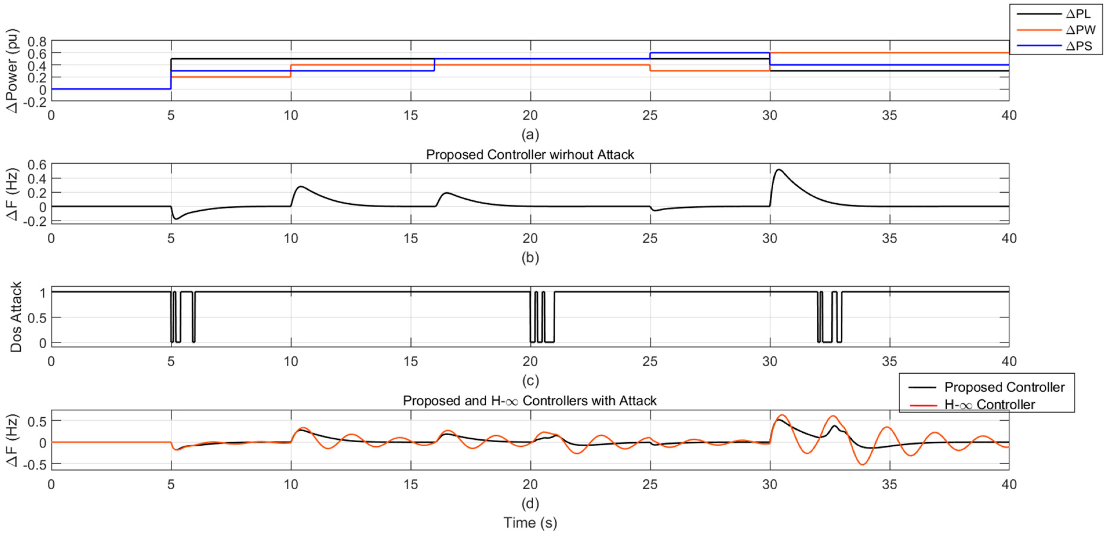
4.1.2. Case 2: Multiple-Step Disturbances in Wind Power, Solar Power and Load Power

Multi-step disturbances in the wind, solar, and load power were also investigated, with step changes happening at 5, 10, 15, 16, 25, and 30 s, as shown in Table 3. Figure 5a shows the pattern of several load step changes. Figure 5b shows the MG frequency change response without attack. Figure 5c displays a DoS attack as well as step changes in load, wind, and solar power. Figure 5d shows the MG frequency change response using the proposed tracker and the H controller under the above-mentioned disturbances and a DoS attack.
The recommended tracker outperformed the H controller in terms of percentage overshoot, settling time, rising time, and steady-state error.

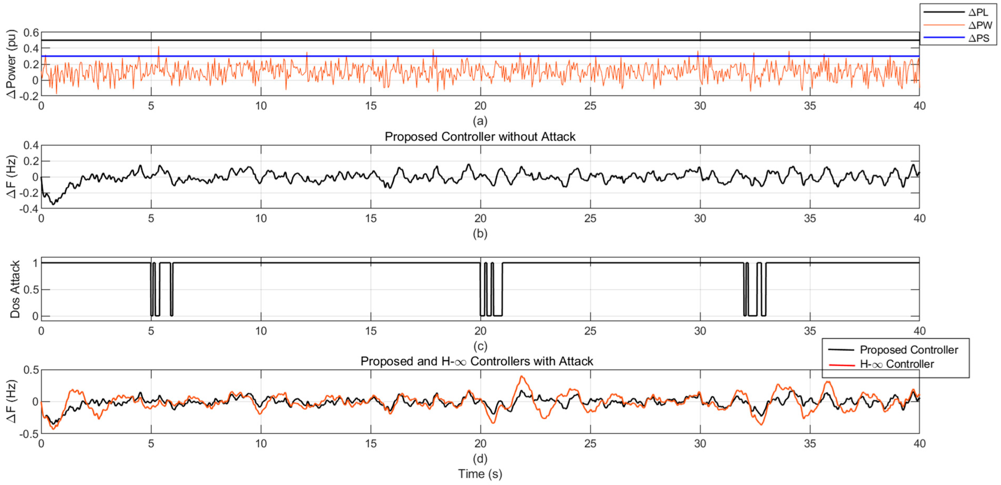
4.2. Scenario 2: Stochastic Disturbance in Wind Power

The MG frequency response under stochastic disturbances in wind power is examined in Figure 6a. The solar and load powers are kept constant at 0.3 pu and 0.5 pu, respectively. Figure 6b illustrates the MG frequency change response without a DoS attack. Figure 6c illustrates the DoS attack with stochastic disturbances in wind power. Figure 6d illustrates the MG frequency change response using the proposed tracker and the H controller. The proposed tracker eliminates the steady-state frequency deviation error and outperforms the H controller. Note that for a stochastic system input, the output will also be stochastic.

4.3. Scenario 3: Robustness Against Parameter Variation

In this scenario, a comparison between the recommended tracker and the H controller is studied. The robustness of the proposed tracker was tested on the studied MG under uncertain parameters, including ±30% deviations in inertia (H), in addition to security against DoS attack. Figure 7a,b show the load step changes and the DoS attack occurrence, respectively. The MG frequency responses of the proposed tracker and H controller are displayed at 100% MG inertia (H) in Figure 7c. Similarly, Figure 7d,e show the MG frequency response using the proposed tracker and the H controller at 130% H and 70% H, respectively. The proposed tracker shows swift and robust responses at 100%, 130%, and 70% MG inertia and during step changes in the load, and it is secure against DoS attack.

5. Conclusions

To effectively and swiftly manage the load frequency for an isolated microgrid against parameter uncertainty and DoS attacks, a new control design method has been proposed. The proposed invariant ellipsoid design provides state feedback with integral control. The analyzed isolated microgrid consists of several different power-generating units, including wind, solar, diesel, fuel cells, and batteries. Presuming that all renewable energy generators are operating at full capacity, the only electricity that can be controlled is that generated by the fuel cell unit and the diesel generator.
The efficacy of the proposed controller was evaluated under different operating conditions and during a denial-of-service (DoS) attack. The operating scenarios covered both deterministic and stochastic load variations, as well as system parameter variations. The microgrid’s load frequency control system, incorporating the proposed tracker, successfully stabilized the system under the above operating scenarios and DoS attacks. The proposed control strategy has demonstrated resilience against DoS attacks and robustness against system uncertainties. The performance analysis revealed the superiority of the proposed control method compared to the H controller. Critically, this method models a DoS attack as uncertainty within the input matrix. The impact of the other uncertainties are treated as an external disturbance. This disturbance is subsequently attenuated through minimization of the ellipsoidal volume.

Author Contributions

Conceptualization, H.S. and E.B.; methodology, H.S. and E.B.; software, H.S. and E.B.; validation, H.S. and E.B.; formal analysis, H.S.; investigation, H.S. and E.B.; resources, S.L.; data curation, E.B. and S.L.; writing—original draft preparation, H.S., E.B. and S.L.; writing—review and editing, H.S., E.B. and S.L.; visualization, H.S. and E.B.; supervision, H.S. All authors have read and agreed to the published version of the manuscript.

Funding

This research received no external funding.

Data Availability Statement

Additional questions can be forwarded to the corresponding author; the article contains the original contributions made throughout the study.

Conflicts of Interest

The authors declare no conflicts of interest.

Abbreviations

The following abbreviations are used in this manuscript:
MGMicrogrid
DoSDenial of service
LMILinear matrix inequality
LFCLoad frequency control
AC-MGAlternating current microgrid
DC-MGDirect current microgrid
AC-DC MGHybrid microgrid
FCFuel cell
DeGDiesel generator
CPSCyber-physical system
TDATime delay attack
FDIFalse data injection
HInertia constant of rotating part in microgrid
DDamping coefficient of microgrid
TfcTime constant of the fuel cell
TinvTime constant of the inverter
TfiltTime constant of the filter
TgTime constant of the governor
TtTime constant of the turbine
TbTime constant of batteries
RDroop frequency

Appendix A. Proof Sketch of Theorem 2

Consider the following discrete-time system:
x k + 1 = A x k + D w k , z k = C x k
where x k ,   w k ,   a n d   z k are the vectors of state, external disturbance, and output to be optimized for dimensions n, p, and l, respectively. The disturbance is subject to the following constraint:
w k 1 , k = 0,1 , 2 ,
The ellipsoid
E = x k P 1 x k 1 ,   P > 0
centered at the origin is termed attractive and state-invariant, as explained before, for Equations (A1) and (A2), if and only if the following theorem is satisfied:
Theorem A1 [27]
α P * * A P P * 0 D 1 α I 0   subject   to   P > 0 ,   t h e   s c a l a r   α > 0
Proof
Consider the Lyapunov function:
V x k = x k Q x k ,   Q = P 1 > 0
The trajectory x k of System (A1) will not leave Ellipsoid (A3) if and only if the following is satisfied:
V x k + 1 1 A x k + D w k A A x k + D w k 1 ,   s u b j e c t   t o   V x k 1 ,   w k w k 1
Equation (A6) is derived by introducing the augmented vector s = x w . Using the S-procedure gives the following:
A Q A α Q A Q D * D Q D α I 0
The proof of Theorem (A1) is derived from Equation (A7) using the Lemma of matrix inversion and congruence transformation [24].
For state feedback control, System (A1) becomes the following:
x k + 1 = A x k + B u k + D w k , z k = C x k
Substituting u k = K x k and replacing A   b y   A + B K in Theorem (A1) gives the following:
α P * * ( A P + B Y ) P * 0 D 1 α I 0       s u b j e c t   t o   P > 0 ,   t h e   s c a l a r   α > 0
where
Y = K P
The controller K is obtained by solving Equation (A10). The effect of the disturbance on the system’s performance is attenuated by minimizing the ellipsoid volume; therefore, Equation (A9) becomes the following:
m i n i m i z e   t r P   s . t . α P * * ( A P + B Y ) P * 0 D 1 α I 0 ,     P > 0 , α > 0  
When there are uncertainties in A, B, and D, Theorem 2 can be easily obtained using Fact 1.

References

  1. Bevrani, H.; François, B.; Ise, T. Microgrid Dynamics and Control, 1st ed.; John Wiley & Sons, Inc.: Hoboken, NJ, USA, 2017; pp. 435–486. [Google Scholar]
  2. Mahmoud, M.S.; AL-Sunni, F.M. Control and Optimization of Distributed Generation Systems, 2015th ed.; Springer International Publishing: Cham, Switzerland, 2015. [Google Scholar]
  3. Bayoumi, E.H.E.; Soliman, H.M.; Albadi, M.; Soliman, M. Invariant set design of decentralized control for islanded microgrids under plug-and-play operation. Int. J. Electr. Power Energy Syst. 2021, 128, 106678. [Google Scholar] [CrossRef]
  4. Kammer, C.; Karimi, A. Advanced Droop Control in Islanded Microgrids Using Dynamic Phasor Models. IFAC-Pap. Online 2017, 50, 6642–6647. [Google Scholar] [CrossRef]
  5. Soliman, H.M.; Bayoumi, E.H.E.; El-Sheikhi, F.A.; Ibrahim, A.M. Ellipsoidal-Set Design of the Decentralized Plug and Play Control for Direct Current Microgrids. IEEE Access 2021, 9, 96898–96911. [Google Scholar] [CrossRef]
  6. Awad, H.; Bayoumi, E.H.E.; Soliman, H.M.; De Santis, M. Robust tracker of hybrid microgrids by the invariant-ellipsoid set. Electronics 2021, 10, 1794. [Google Scholar] [CrossRef]
  7. Mahmoud, M.S. Microgrid: Advanced Control Methods and Renewable Energy System Integration, 1st ed.; Elsevier Inc.: Amsterdam, The Netherlands, 2017. [Google Scholar]
  8. Soliman, H.M.; Saleem, A.; Bayoumi, E.H.E.; De Santis, M. Harmonic Distortion Reduction of Transformer-Less Grid-Connected Converters by Ellipsoidal-Based Robust Control. Energies 2023, 16, 1362. [Google Scholar] [CrossRef]
  9. Awad, H.; Soliman, H.M.; Bayoumi, E.H.E. Disturbance-Rejection Control for Unbalanced Operation of Microgrids: Invariant-Set Approach. ISA Trans. 2024, 153, 334–349. [Google Scholar] [CrossRef]
  10. Mahmoud, M.S.; Khalid, H.M.; Hamdan, M.M. Cyber-physical infrastructures in power systems: Architectures and Vulnerabilities. In Aca, 1st ed.; Elsevier Inc.: Amsterdam, The Netherlands, 2021. [Google Scholar]
  11. Veronica, A.J.S.J.; Kumar, N.S.; Longatt, F.G. Robust PI controller design for frequency stabilization in a hybrid microgrid system considering parametric uncertainties and communication time delay. IET Gener. Transm. Distrib. 2019, 13, 3048–3056. [Google Scholar] [CrossRef]
  12. Duo, W.; Zhou, M.; Abusorrah, A. A Survey of Cyber Attacks on Cyber Physical Systems: Recent Advances and Challenges. IEEE/CAA J. Autom. Sin. 2022, 9, 784–800. [Google Scholar] [CrossRef]
  13. Nejabatkhah, F.; Li, Y.W.; Liang, H.; Ahrabi, R.R. Cyber-security of smart microgrids: A survey. Energies 2021, 14, 27. [Google Scholar] [CrossRef]
  14. Xiahou, K.S.; Liu, Y.; Wu, Q.H. Robust load frequency control of power systems against random time-delay attacks. IEEE Trans. Smart Grid 2020, 12, 909–911. [Google Scholar] [CrossRef]
  15. Zhang, J.; Xia, Y.; Sun, Z.; Chen, D. Networked and Event-Triggered Control Approaches in Cyber-Physical Systems, 1st ed.; CRC Press: Boca Raton, FL, USA, 2022. [Google Scholar] [CrossRef]
  16. Sahoo, S.; Yang, Y.; Blaabjerg, F. Resilient synchronization strategy for AC microgrids under cyber-attacks. IEEE Trans. Power Electron. 2021, 36, 3–77. [Google Scholar] [CrossRef]
  17. Bi, J.; Luo, F.; He, S.; Liang, G.; Meng, W.; Sun, M. False data injection and propagation aware game: Theoretical approach for microgrids. IEEE Trans. Smart Grid 2022, 13, 3342–3353. [Google Scholar] [CrossRef]
  18. Chen, X.; Hu, S.; Li, Y.; Yue, D.; Dou, C.; Ding, L. Co-estimation of state and FDI attacks and attack compensation control for multi-area load frequency control systems under FDI and DoS attacks. IEEE Trans. Smart Grid 2022, 13, 2357–2368. [Google Scholar] [CrossRef]
  19. Lin, C.; Hu, B.; Shao, C.; Li, W.; Li, C.; Xie, K. Delay-dependent optimal load frequency control for sampling systems with demand response. IEEE Trans. Power Syst. 2022, 37, 4310–4324. [Google Scholar] [CrossRef]
  20. Khalili, J.; Dehkordi, N.M.; Hamzeh, M. Distributed event-triggered secondary frequency control of islanded AC microgrids under cyber attacks with input time delay. Int. J. Electr. Power Energy Syst. 2022, 143, 108506. [Google Scholar] [CrossRef]
  21. Hu, S.; Ge, X.; Chen, X.; Yue, D. Resilient load frequency control of islanded AC microgrid under concurrent false data injection and denial-of-service attacks. IEEE Trans. Smart Grid 2023, 14, 690–700. [Google Scholar] [CrossRef]
  22. Zhao, X.; Zou, S.; Wang, P.; Ma, Z. Bandwidth-aware event-triggered load frequency control for power systems under time-varying delays. IEEE Trans. Power Syst. 2023, 38, 4530–4541. [Google Scholar] [CrossRef]
  23. Qiao, S.; Liu, X.; Liang, Y.; Xiao, G.; Kang, Y.; Ge, S.S. Event-triggered sliding mode load frequency control of multiarea power systems under periodic denial-of-service attacks. IEEE Syst. J. 2023, 17, 2803–2814. [Google Scholar] [CrossRef]
  24. Poznyak, A. Robust Control: Supplementary Topics, 1st ed.; Cambridge Scholars Publishing: Cambridge, MA, USA, 2024. [Google Scholar]
  25. Tudu, A.K.; Naguru, N.; Dey, S.H.N.; Paul, S. Load frequency control of an isolated microgrid using optimized model predictive control by GA. Electr. Eng. 2024, 106, 4171–4183. [Google Scholar] [CrossRef]
  26. Mahmoud, M.S.; Hamdan, M.M.; Baroudi, U.A. Modeling and control of Cyber-Physical Systems subject to cyber attacks: A survey of recent advances and challenges. Neurocomputing 2019, 338, 101–115. [Google Scholar] [CrossRef]
  27. Khlebnikov, M.V.; Polyak, B.T.; Kuntsevich, V.M. Optimization of Linear Systems Subject to Bounded Exogenous Disturbances: The Invariant Ellipsoid Technique. Autom. Remote Control. 2011, 72, 2227–2275. [Google Scholar] [CrossRef]
  28. Werner, H.; Korba, P.; Yang, T.C. Robust Tuning of Power System Stabilizers Using LMI-Techniques. IEEE Trans. Control. Syst. Technol. 2003, 11, 147–152. [Google Scholar] [CrossRef]
  29. The MathWorks, Inc. MATLAB Version: 9.13.0 (R2023b). 2023. Available online: https://www.mathworks.com (accessed on 11 December 2024).
  30. Lofberg, J. YALMIP: A toolbox for modeling and optimization in MATLAB. In Proceedings of the 2004 IEEE International Conference on Robotics and Automation (IEEE Cat. No.04CH37508), Taipei, Taiwan, 2–4 September 2004; pp. 284–289. [Google Scholar] [CrossRef]
  31. Löfberg, J. Modeling and solving uncertain optimization problems in YALMIP. IFAC Proc. Vol. 2008, 41, 1337–1341. [Google Scholar] [CrossRef]
  32. Labit, Y.; Peaucelle, D.; Henrion, D. SEDUMI INTERFACE 1.02: A tool for solving LMI problems with SEDUMI. In Proceedings of the IEEE International Symposium on Computer Aided Control System Design, Glasgow, UK, 18–20 September 2002; pp. 272–277. [Google Scholar] [CrossRef]
  33. Henrion, D.; Lasserre, J.-B. GloptiPoly: Global optimization over polynomials with Matlab and SeDuMi. In Proceedings of the 41st IEEE Conference on Decision and Control 2002, Las Vegas, NV, USA, 10–13 December 2002; Volume 1, pp. 747–752. [Google Scholar] [CrossRef]
  34. Wong, W.K.; Yin, Y.; Zhou, J. Using SeDuMi to find various optimal designs for regression models. Stat Pap. 2019, 60, 1583–1603. [Google Scholar] [CrossRef]
Figure 1. Block schematic of the DoS-attacked closed-loop system.
Smartcities 08 00039 g001
Figure 2. Schematic of the proposed microgrid system.
Smartcities 08 00039 g002
Figure 3. Control scheme with integral control.
Smartcities 08 00039 g003
Figure 4. Multiple-step disturbance: (a) load power, wind power, and solar power; (b) MG frequency change response using the proposed controller without DoS attack; (c) DoS attack; (d) MG frequency change response using the proposed and H controllers with DoS attack.
Smartcities 08 00039 g004
Figure 5. Multiple-step disturbances in wind power, solar power, and load power: (a) load power, wind power, and solar power; (b) MG frequency change response of the proposed controller without DoS attack; (c) DoS attack; (d) MG frequency change response of the proposed and H controllers with DoS attack.
Smartcities 08 00039 g005
Figure 6. Stochastic disturbance in wind power: (a) load power, wind power, and solar power; (b) MG frequency response of the proposed controller without DoS attack; (c) DoS attack; (d) MG frequency response of the recommended and H controllers with DoS attack.
Smartcities 08 00039 g006
Figure 7. Robustness against inertia variation (±30% H): (a,b) step changes in load power and the DoS attack, respectively; (c) MG frequency change response at 100% MG inertia; (d) MG frequency change response at 130% MG inertia; (e) MG frequency change response at 70% MG inertia.
Smartcities 08 00039 g007
Table 1. MG system parameters [25].
ParameterValueParameterValue
D (p.u. MW/Hz)0.015Tg(s)0.08
2H(s)0.1667Tt0.4
Tfc(s)0.26Tb(s)0.1
Tinv(s)0.04R (Hz/p.u. MW)3
Tfilt(s)0.004
Table 2. Timing of the DoS attacks.
Attack #TimeStatus
1t = 5 sDuring step change
2t = 20 sAt normal operation
3t = 32 sDuring frequency settling
Table 3. Timing of the multi-step disturbances in Scenario 2.
Attack #TimeLoad PowerWind PowerSolar Power
1t = 5 s0.50 pu0.20 pu0.30 pu
2t = 10 s0.50 pu0.40 pu0.30 pu
3t = 16 s0.50 pu0.40 pu0.50 pu
5t = 25 s0.50 pu0.30 pu0.60 pu
6t = 30 s0.30 pu0.60 pu0.40 pu
Disclaimer/Publisher’s Note: The statements, opinions and data contained in all publications are solely those of the individual author(s) and contributor(s) and not of MDPI and/or the editor(s). MDPI and/or the editor(s) disclaim responsibility for any injury to people or property resulting from any ideas, methods, instructions or products referred to in the content.

