Article

Noise-Reducing Structure Optimization of Inverted Bucket Steam Valves Based on SVM-NOA

1
School of Petrochemical Engineering, Lanzhou University of Technology, Lanzhou 730050, China
2
Machinery Industry Pump Special Valve Engineering Research Center, Lanzhou 730050, China
*
Author to whom correspondence should be addressed.
Acoustics 2025, 7(4), 74; https://doi.org/10.3390/acoustics7040074
Submission received: 11 July 2025 / Revised: 6 November 2025 / Accepted: 7 November 2025 / Published: 13 November 2025
(This article belongs to the Special Issue Vibration and Noise (2nd Edition))

Abstract

The inverted bucket steam valve is a key piece of equipment in steam systems. Optimizing its noise reduction performance via intelligent algorithms is crucial for enhancing the stability of steam systems. In this study, the nutcracker optimization algorithm (NOA) was investigated and improved. A simulation method coupling computational fluid dynamics (CFD) with acoustic software was employed to characterize the acoustic properties of inverted bucket steam valves equipped with noise-reducing elements of different structures. Subsequently, the structural dimensions of the valve’s noise-reducing element were optimized using a support vector machine (SVM)-based surrogate model and the improved NOA. Concurrently, experimental tests were conducted on the inverted bucket steam valve before and after optimization to validate the simulation accuracy. The experimental results demonstrate that the SVM-NOA increases the maximum transmission loss (TL) of the valve’s noise-reducing element by 44.14 dB, with the error between experimental and simulation results being less than 3%. This verifies the accuracy of the acoustic simulation method and confirms the practicality and versatility of the SVM-NOA for solving real-world engineering problems.

1. Introduction

Steam energy is widely used as a secondary energy source in thermal power, petroleum, chemical, light industry and other fields. The inverted bucket steam valve is an important form of steam valve, an indispensable device in the steam system, and a key device for condensate recovery. It plays the role of a steam valve that blocks the passage of water and exhausts air and is of great significance in making full use of the latent heat of steam and improving the energy efficiency of the steam system. When working under high parameter conditions, inverted bucket steam valves have many problems. When condensate is throttled by the valve, the resulting turbulent pressure pulsation will produce intense turbulence, resulting in the loss of mechanical energy of the fluid medium, a portion of which will be transformed into acoustic energy and radiate outflow noise, which will cause damage to the valve and piping to varying degrees, and reduce the service life of the equipment and piping. In the initial state, the barrel naturally droops. After the valve is opened, condensed water is injected into the valve chamber to form a liquid seal. The barrel is reset by fluid impact. Due to the same density of the medium inside and outside the barrel, the buoyancy is insufficient to offset its own weight. When the barrel sinks, the linkage valve core component opens for drainage. When steam flows in, the inverted barrel generates buoyancy, which drives the valve core to move upward and close the valve. As the steam gradually condenses, the buoyancy weakens to the critical value. The barrel opens for drainage again under the action of gravity, and the cycle repeats. The hot condensed water in the valve is recovered, forming a hot condensed water recovery steam trap and valve control pipe system. Due to the coupling of turbulent pulsation and condensed water during the throttling process of valves, the noise of steam traps and valve control piping systems exhibits significant nonlinear acoustic characteristics during the operation of steam systems. Such noise is a visual representation of energy loss in steam systems. So, it is important to study the acoustic characteristics of inverted bucket steam valves. The study of acoustic characteristics of inverted bucket steam valves is of great significance. A study of the noise problem of high parameter pressure reducing valves by Chen et al. [1] showed that porous plates can be effectively applied for noise control at the outlet of pipelines and French doors. Zhou et al. [2] considered the effect of the vibration of the micro-porous plate itself on the cavity sound field, proposed a plate–cavity coupling model to calculate the noise reduction performance of the microporous plate, and optimized the micro-porous plate perforation rate, aperture diameter, and plate thickness. Li et al. [3] used a reduced-pressure orifice plate as a simplified model of the multi-stage throttling internal parts of the valve regulator. Based on the computational fluid dynamics method of different opening spacings and different opening forms of the orifice plate model for jet flow characteristics of numerical simulations and the experimental validation, the results show that the orifice plate opening spacing of more than 20 mm, the media flow rate and so on have been reduced. Su et al. [4] and others applied CFD technology to simulate the dynamic characteristics of the relief valve, derived the main reasons for the noise generated by the fuel pump system, and optimized the clearance between the spool and the valve body for noise reduction. Jiang et al. [5] performed a numerical simulation of submarine hydrodynamic noise using the boundary element method and the traditional FW-H equation and compared the numerical simulation results with the experimental values, showing that the boundary element method is closer to the experimental results. Li et al. [6] predicted the aerodynamic noise of steam turbine control valves by the sound path and source approximation method, which provides guidance for the control of aerodynamic noise of control valves. Meng et al. [7] took the aerodynamic noise generated by gas flowing through the valve as the research object, and numerical simulation calculations were carried out by using the method of software linkage, and the results showed that the velocity pulsation and pressure pulsation of the fluid were the fundamental causes of aerodynamic noise generation, and the dipole sound source dominated at low Mach numbers. Zhang et al. [8] used the computational fluid dynamics method to calculate the flow field of the minimum flow circulation valve of the boiler feed pump and used the FW-H equation to analyze the noise characteristics and noise sources of the valve. On this basis, the valve outlet structure is modified to better suppress the noise propagation. Yang et al. [9] considered the reflection or transmission of incident waves at the exit boundary and applied passive metamaterials to sound absorption in the low-frequency domain with deep subwavelength dimensions; this approach has been widely used in one-dimensional inverse problems. However, the generalized problem of impedance boundary conditions remains unclear.
Valves, pumps, and other valve control system components of the noise reduction structure optimization, stability analysis, etc., are currently the main direction of the system optimization research. Xu et al. [10], based on the accurate theory of a micro-perforated plate acoustic absorber, used the particle swarm optimization algorithm for the resonance frequency of micro-perforated plate structural parameters to optimize the perforated plate structural model by taking the urban rail traffic noise as an example and verified this by numerical experiments. Nie et al. [11], based on the dynamic characteristics of the solenoid valve simulation model, the use of genetic algorithms to optimize the key structural parameters of the solenoid valve, the study of the structural parameters of the solenoid valve dynamic response characteristics of the influence of the law, and, through the comparison of the simulation results with the experimental results, verified the accuracy of the simulation model. The research results show that for the optimized solenoid valve, after the reduction in the overall response time of 0.25 ms, the dynamic response speed improved by 31.7%. Xie et al. [12] proposed a multi-objective genetic algorithm-based axial-piston pump low-pulsation structure optimization design method; simulation results show that for the optimized structure, the flow pulsation rate is 12.02%. Compared with the pre-optimization flow pulsation rate, which was reduced by 43.59%, the pressure pulsation was reduced by 0.16%, proving that genetic algorithms can be applied to engineering practice. Ji et al. [13] proposed an integrated optimal design method by combining intelligent optimization algorithms with generative design, and the results of the study showed that the mass of the structure generated by the integrated optimization method was reduced by 27%, the intrinsic energy was increased by a factor of 0.95, and the superiority of the proposed optimal structural design method was confirmed by the qualitative study and analysis of the experimental results. Jafari Malihe et al. [14] proposed an efficient hybrid algorithm for the optimal design of truss structures based on the particle swarm optimization (PSO) algorithm and cultural algorithm (CA). The performance of PSOC was evaluated using a set of five common truss design examples, and the results show that PSOC is suiFigure for an engineering design to obtain the optimized design dimensions of the optimal truss structures. Chen et al. [15] established an aerodynamic optimization design platform for a local inlet turbine using an artificial neural network combined with the particle swarm genetic hybrid method, and the results showed that the optimized turbine’s internal flow state was significantly improved, the flow separation due to the local inlet was eliminated, and the total static efficiency of the local inlet turbine was improved by 3.72% compared with that of the prototype. Xu et al. [16] proposed an optimization method for an annular jet pump based on a radial basis function (RBF) neural network model and non-dominated sorting genetic optimization algorithm (NSGA-II); the results show that the optimized model’s suction angle increases, the diffusion angle, flow ratio, and area ratio decrease, and the head ratio increases by 30.46%. Nouhi B et al. [17] proposed the group optimizer with a mechanism-based approach to find the optimal steel frame and the results show that the performance of the new approach can be demonstrated by solving two structural problems, and the weight efficiency of the optimized steel frame is increased. Zhu et al. [18] proposed an optimization method to reduce the sound pressure level of composite laminates by combining the response surface method (RSM) with the genetic optimization algorithm, and the results show that the use of this method to analyze the noise characteristics of composite laminates can significantly improve the optimization efficiency and provide a reference for the engineering practice. The results show that using this method to analyze the noise characteristics of composite laminates can significantly improve the optimization efficiency and provide reference for engineering practice. Zhang et al. [19] solved the application of dual indicators based on the reference point non-dominated genetic algorithm (PB-NSGA-III) and found a combination of geometric parameters to meet the performance requirements for the establishment of the impeller geometric parameters and the performance parameters of the pipe relationship between the impeller multi-objective optimization method and the optimized high-speed centrifugal pump. In the design of the working condition of the pump, hydraulic efficiency increased by 2.2%, and numerical simulation results and the performance parameters obtained by the optimization method have good consistency. The optimized high-speed centrifugal pump has improved hydraulic efficiency by 2.2% in the design working conditions, and the numerical simulation results are in good agreement with the performance parameters obtained by the optimization method. Jin et al. [20] used a computational fluid dynamics (CFD) data set to train a CNN to establish the mapping relationship between the pressure fluctuation on the cylinder and the velocity field around the cylinder.
To summarize, although existing research has advanced the simulation of flow-induced noise and the optimization of noise-reducing structures, two key limitations remain. First, few studies have focused on the unique acoustic properties of high-temperature and high-pressure steam traps, and detailed analysis of flow field–acoustic field coupling within the valve is lacking. Second, most optimization studies have centered on the algorithms themselves, with insufficient experimental validation of optimization results and inadequate discussion of the underlying acoustic mechanisms.
Therefore, this paper takes the PN40 DN100 inverted bucket steam trap as the research object and focuses on establishing its high-precision flow-induced acoustic prediction model and verifying it through experiments. In order to solve the computational cost problem in the optimization process, this paper uses the strategy of combining a SVM approximate model and the NOA to optimize the structure of the porous noise reduction plate. The ultimate goal of the study is to clarify the mechanism of noise reduction through detailed simulation and experimental comparison and provide a reliable methodology for a low-noise design of valves.

2. Nutcracker Optimization Algorithm

In the process of structural optimization for the inverted bucket steam valve noise reduction orifice plate, the efficiency can be improved by using optimization algorithms which have various forms. In this paper NOA is chosen; NOA is a novel algorithm based on the different behaviors of the nutcrackers’ nature-inspired meta-heuristic algorithm [21].
Initially, the position of the nutcrackers is random, i.e., some points are randomly generated in the search space of the problem, assuming that the population size is N and the problem dimension is D. The initialization formula is as follows:
X i j t = + ( U j L j ) R M + L j
where i = 1, 2 …, N; j = 1, 2 …, D. Xij denotes the j th dimensional variable of individual i, and Lj and Uj denote the next and previous terms of the j th dimensional variable, respectively, R M is the random vector between [0, 1].
By storing food in summer and retrieving cached food based on spatial memory in winter, the behavior of the nutcracker achieves a balance between global exploration and local development. During the optimization process, each nutcracker keeps updating the exploration position according to the reference point; they will apply the exploration mechanism to search for the most promising food area, and the algorithm will explore and utilize the area around the cache with appropriate Rp in order to avoid falling into the local minima. The second stage of the exploitation position update formula is shown in Equation (2):
X i t + 1 = X i t                   i f   f ( X i t ) < i f   R P i , 1 t R P i , 1 t                   O t h e r w i s e
where X i t + 1 represents the new position of the first nutcracker at iteration (t + 1), X i t is the current position of the i th nutcracker in the current iteration t.
Depending on the optimization problem, the balancing of the exploration and development phases in the balancing algorithm of Equation (3) is applied.
X i t + 1 = X i t + 1 ,           if   f ( X i t + 1 )   <   f ( X i t ) X i t ,                         O t h e r w i s e
Logistic chaos mapping is used to improve the population initialization of the star sparrow optimization algorithm; logistic chaos mapping is a typical representative of chaotic mapping, and its mathematical expression is shown in Equation (4).
f ( x n + 1 ) = a f ( x n ) ( 1 f ( x n ) )
In Equation (4), f(xn) ∈ [0, 1], ɑ is the logistic parameter, and the range of values is [0, 4]. According to experimental results [22], the closer the logistic parameter gets to 4, the more evenly the range of values of f(xn) is distributed throughout the range [0, 1]. In the text, ɑ = 3.9999 and f(xn) = 0.5.

3. Acoustic Modeling and Optimization Methods

3.1. Optimized Design Model of Noise Reduction Element

The inverted bucket steam valve within the noise reduction element design is a very complex problem. In practice, the selection of the structure of the significant effect of the factors acts as the design variable, holding other non-critical factors as constant. The difference in aperture will change the local flow field characteristics and affect the acoustic impedance matching effect. The distance between holes determines the jet interaction and acoustic interference effect between holes; the thickness of the orifice plate determines the propagation path and friction dissipation of sound waves in the hole. Therefore, for optimization of the structure of the noise reduction element within the bucket steam valve, the aperture, hole spacing, and thickness of orifice plate are chosen for the design variables, as shown in Equation (5).
X = ( x 1 , x 2 , x 3 )
where x1 is the aperture, x2 is the hole spacing, and x3 is the thickness of orifice plate.
The values of the design variables are shown in Table 1.

3.2. SVM-NOA-Based Noise Reduction Optimization Method

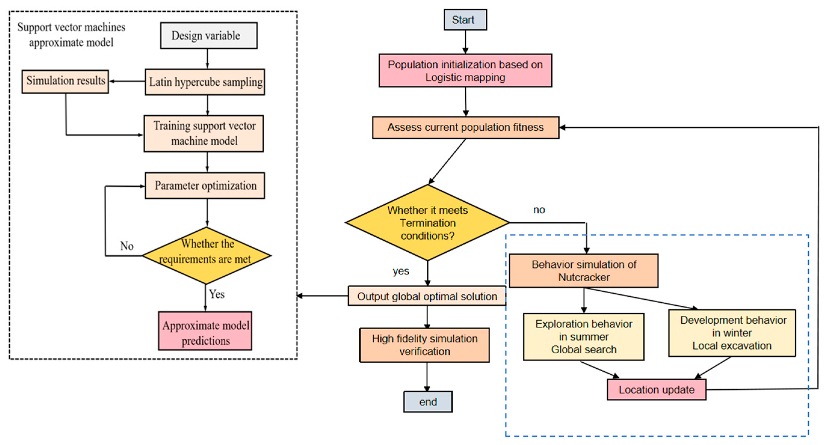
Due to the huge computational volume of the acoustic analysis of the inverted bucket steam valve and the time-consuming long optimization, which leads to the low efficiency of the optimal design of the noise reduction structure, the acoustic analysis of the noise reduction elements with different structural parameters in the inverted bucket steam valve is firstly carried out to obtain the sample data set D = {(xi,yi), i = 1, 2, 3 ……}. At the same time, this data set is used to establish the support vector machine approximation model of the noise reduction structure inside the inverted bucket steam valve, the SVM approximation model of the noise reduction structure inside the inverted bucket steam valve is applied for the computation, and the optimal solution is solved by using the NOA genetic algorithm; the process is shown in Figure 1.

4. Acoustic Analysis of Noise Reduction Elements with Different Structural Parameters

4.1. Inverted Bucket Steam Valve Structure

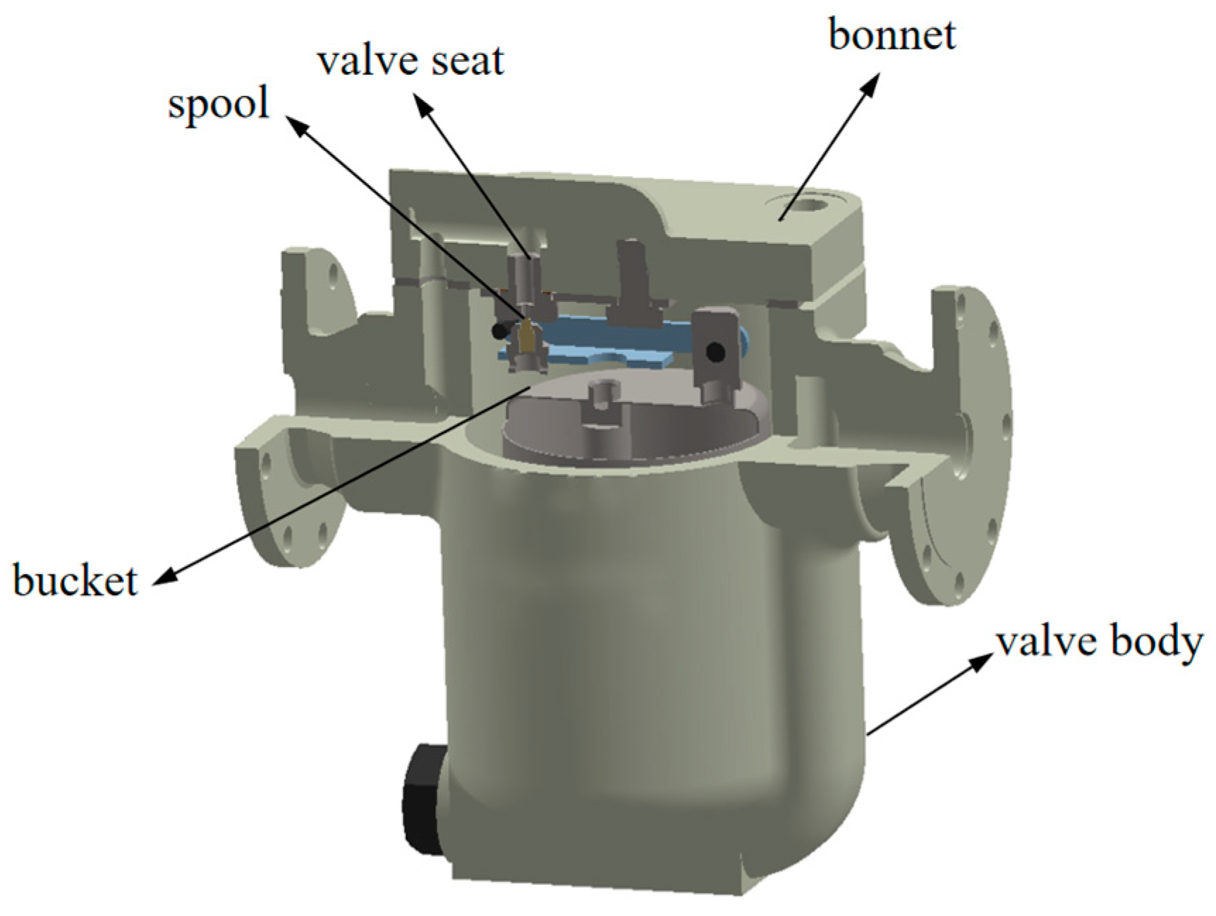
The PN40 DN100 inverted bucket steam valve is the object of study, and the basic principle of work is to use the density difference between condensate and steam so that the inverted bucket produces upward buoyancy, so as to achieve the purpose of regulating the pressure to achieve the closure of the valve. Its structure is shown in Figure 2. It consists of a valve body, valve cover, inverted bucket, valve seat, spool, etc.

4.2. Acoustic Simulation Theory

Currently, the acoustic simulation methods applied to the valve flow noise are mainly divided into three categories, which are the computational pneumatic acoustic method, Wright-Hill acoustic analogy method, and hybrid computation method. Considering the computational accuracy and the applicable conditions, the paper selects the hybrid computation method to simulate the noise of an inverted bucket steam valve, which refers to the acoustic simulation method combining the CFD simulation and acoustic analogy theory, and the results of non-constant flow calculation are output in the CGNS format. Firstly, the non-constant flow is calculated in the fluid software, and the results of the non-constant flow are output in the CGNS format, and then the pressure pulsation information is imported into the acoustic software to simulate and calculate the flow-induced noise.
Fluent and LMS Virtual.Lab were used to simulate and analyze the external noise of the inverted bucket steam valves. Based on the Lighthill acoustic analogy theory, the sound pressure fluctuation equations and Helmholtz acoustic equations were used for the simulation and analysis; the continuity equations of sound pressure fluctuation, the equations of motion, and the equations of state are shown in Equations (6)–(8).
ρ 0 + ρ t = ρ 0 + ρ q ρ 0 + ρ v
ρ 0 + ρ t + v v = p 0 + p
p = γ   p 0 ρ 0 ρ + γ ( γ 1 ) 2 ρ 0 2 ρ 2 +
where p0, ρ0, v0 are sound pressure, density, and velocity at rest, respectively, p0′, ρ0′, v0′ are the changes in fluid acoustic pressure, density, and velocity caused by external perturbations, respectively, and γ is the medium specific heat ratio.
The acoustic Helmholtz equation is derived from the continuity equation, the equation of motion, and the equation of state of matter of sound waves as shown in Equation (9).
2   p x , y , z k 2   p x , y , z = j   ρ 0 ω q x , y , z
where k is the wave number, ω is the angular frequency.
The transmission loss is used to measure the noise reduction performance of acoustic elements, which is defined as the logarithm of the ratio of incident sound energy to transmitted sound energy, as shown in Equation (10). The larger the transmission loss, the more significant the noise suppression effect.
T L = 10 lg W i n W o u t
where TL is the transmission loss, unit of dB; Win is the incident sound power, unit of W; Wout is the transmitted sound power, unit of W.

4.3. Acoustic Performance Analysis of Noise Reduction Components

In order to determine the acoustic performance of inverted bucket steam traps after joining the noise reduction structure, a hybrid calculation method of CFD software 2022R1 and LMS.Virtual.Lab software 13.6 is adopted.
In order to achieve a high-precision CFD flow field simulation, under the premise of ensuring the calculation accuracy, the three-dimensional geometric model of a steam trap and valve control system is reasonably simplified. In order to ensure the stability of fluid flow at the inlet and the full development of turbulence at the outlet, the front and rear pipe lengths are guaranteed on the steam trap and valve control pipe system model. In the process of mesh generation, the flow channel shape in the steam trap and valve control piping system model is complex, so tetrahedron/hexahedron hybrid mesh is used to mesh the flow channel model. Considering the requirements of the grid number and solution accuracy, for the case of stable flow and less flow field information, the number of grids can be appropriately reduced to reduce the calculation time on the premise of ensuring the calculation accuracy, and the number of grids can be increased at the valve seat and valve core to achieve a high-precision flow field calculation.
In the case of a large pressure difference, the grid independence verification parameters are shown in Table 2.
Through the comparative analysis in Table 2, it is found that the increase in the number of grid cells has a significant correlation between the accuracy of calculation results and the consumption of computing resources. When the grid density is gradually refined from scheme 1 to scheme 3, the total number of elements reaches 828,384. When the number of grids is increased, the mass flow of the steam trap is basically unchanged, and the error is less than 5%, then it is verified that the meshing has little impact on the calculation, indicating that scheme 2 effectively balances the requirements of calculation efficiency and accuracy while ensuring the ability to capture flow details, so a hybrid grid scheme consisting of 82,731,100 grid cells and 16,335,100 nodes was selected: the grid size of the main flow channel of the valve body is 2 mm, the local area of the valve core throttling zone is densified to 0.5 mm, and the area of the orifice plate is densified to 0.3 mm; five layers of cuboidal boundary layers are set near the wall surface, with the thickness of the first layer being 0.02 mm, and the average y+ value is 58.6, which takes into account both the capture of flow field details and the computational efficiency.
Through the verification of grid independence, the acoustic characteristics of 24 groups of inverted bucket steam traps with different structural parameters of noise reduction elements in the design space were studied, and the specific parameters are as shown in Table 3, Table 4 and Table 5. Table 3 is the comparison group of apertures, Table 4 is the comparison group of hole spacing, and Table 5 is the comparison group with different thickness of orifice plate.
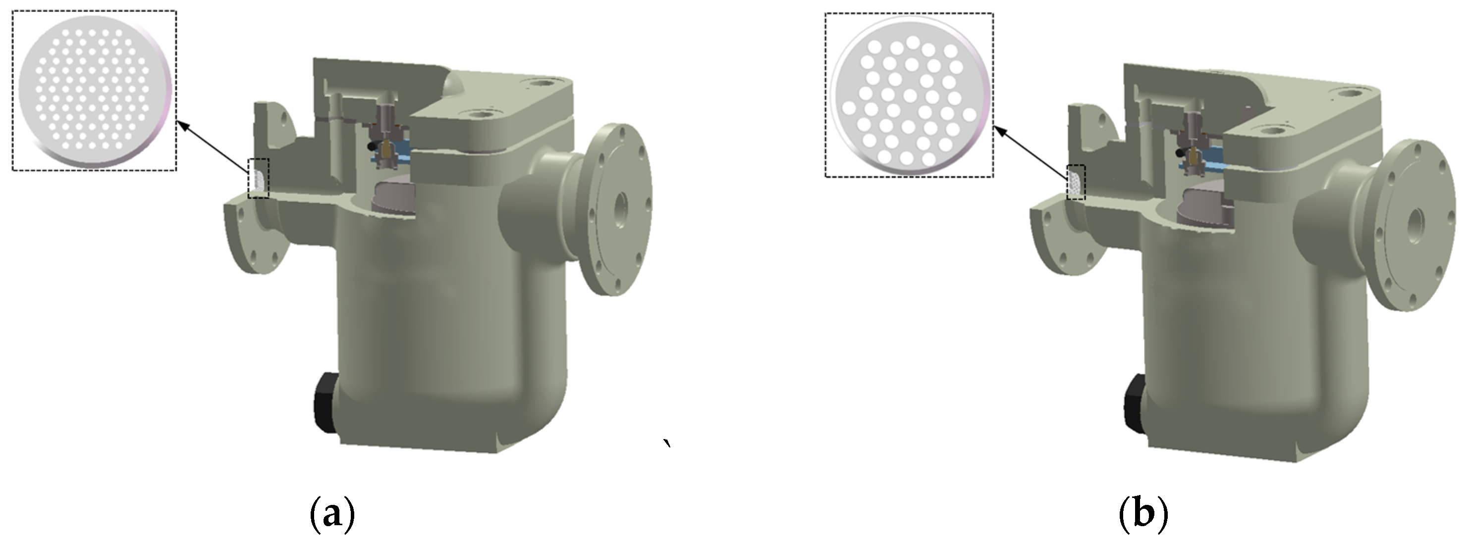
To show the results of the acoustic characterization of the 4.5 mm and 8 mm aperture plates in the unperforated plate and aperture comparison group, the 3D model of the 4.5 mm and 8 mm aperture steam valves is shown in Figure 3. As shown in Figure 4 and Figure 5, the pressure and velocity maps of the steam valve flow field at a certain moment are shown for the unadded noise-reducing orifice plate, with the addition of the noise-reducing orifice plate with an aperture of 4.5 mm and an aperture of 8 mm, respectively.
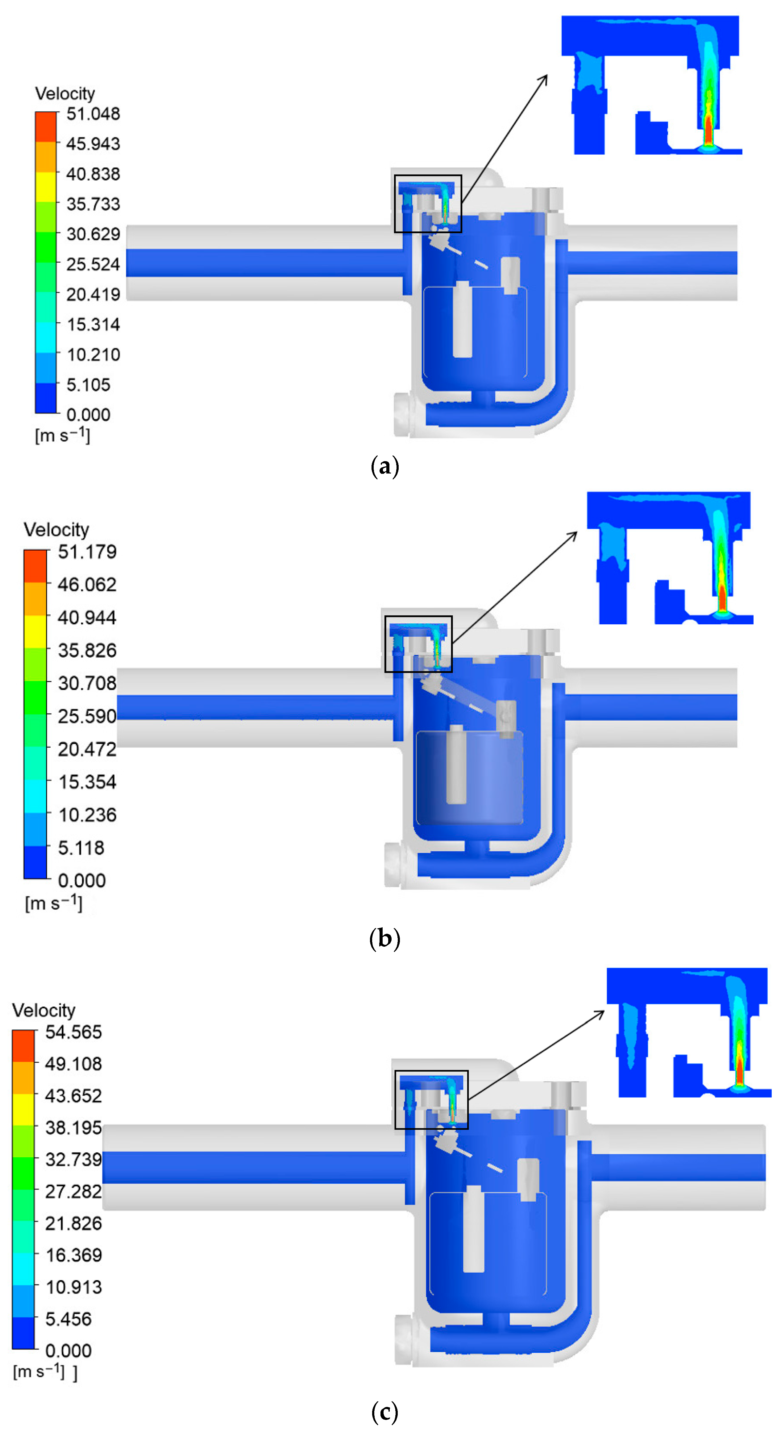
As can be seen from Figure 4, the pressure distribution of the fluid inside the steam valve shows the same pressure drop pattern in all three cases, which is basically consistent with the operating pressure drop of the steam valve and ensures the normal operation of the inverted bucket type steam valve. From Figure 5a, it can be seen that the inverted bucket steam valve studied in this paper, due to the partial throttling effect of the spool, the valve seat, and its rear area form a jet effect, forming a quadrupole sound source. For the noise control of the turbulent quadrupole sound source, a certain number and a certain size of small holes can be set up so that diffusion and attenuation of the noise occurs after it passes through the small holes. A specific size and number of small holes are selected and arranged between the noise source and the receiving point, such that turbulent quadrupole noise diffuses and attenuates upon passing through the small holes, thereby achieving noise reduction [23]. Figure 5 illustrates the internal flow velocity distribution of the valve under the three aforementioned conditions. The fluid passes through the throttling section and eventually enters the valve cavity, with the maximum velocity concentrated in the throttling region and at the orifice plate. As shown in Figure 5b,c, the addition of the orifice plate increases the pressure pulsation, and the flow velocity is concentrated in the throttle area of the valve core and the orifice plate. The reduced aperture leads to the increase in local flow resistance, and the flow velocity changes inversely, which provides the flow field basis for the difference in noise source intensity: the maximum flow velocity reaches 20.83 m/s2 when the orifice plate aperture is 8 mm, and 28.42 m/s2 when the aperture is 4.5 mm.
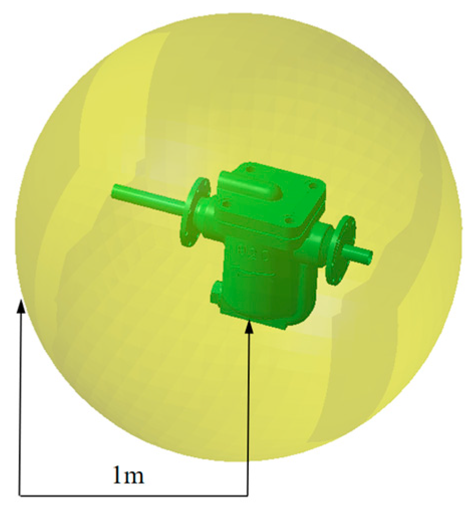
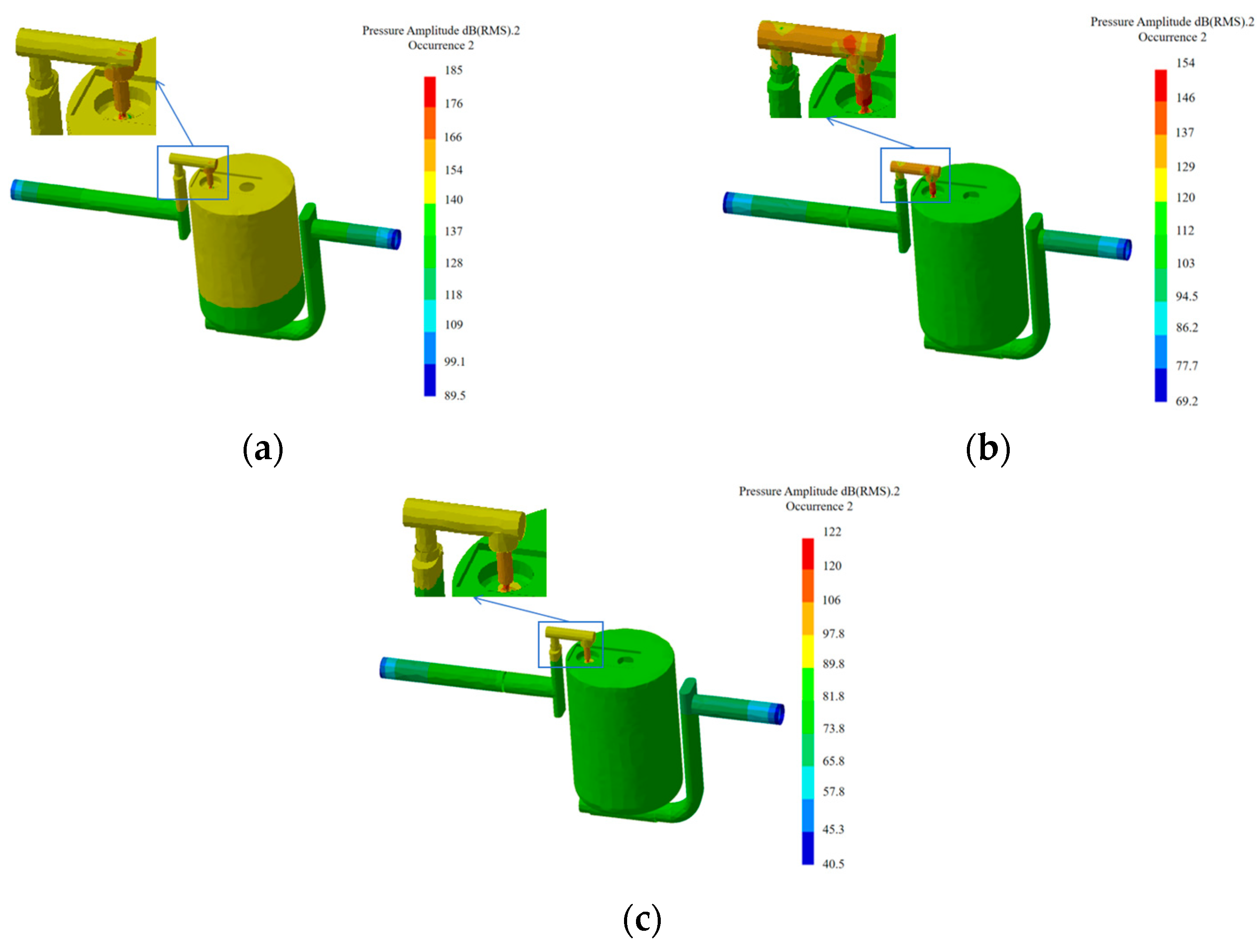
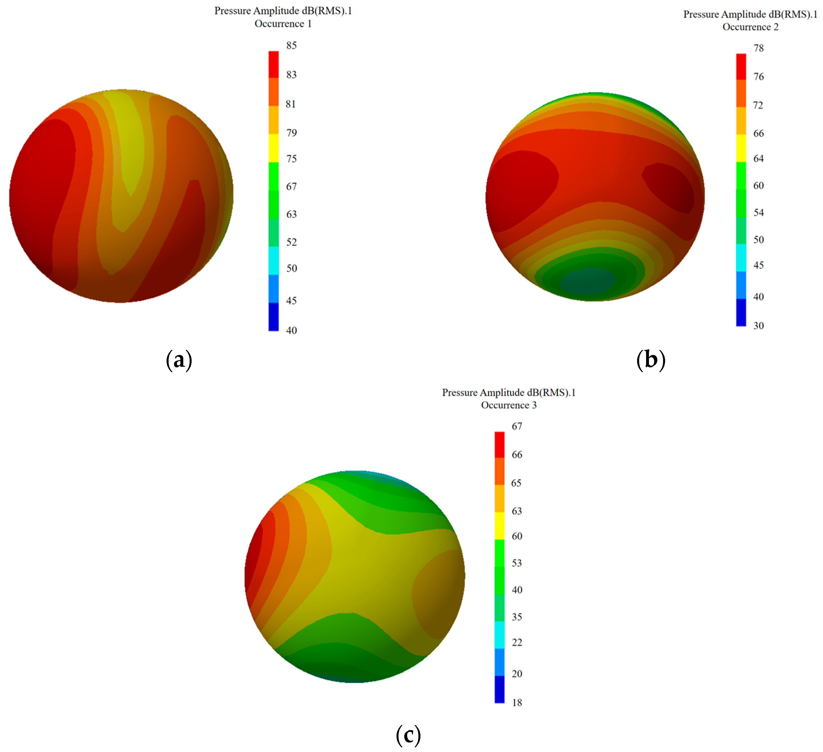
The LMS Virtual.Lab software was applied to set up the spherical sound field monitoring surface one meter outside of the valve, as shown in Figure 6. According to the flow field boundary conditions and sound source excitation, the pressure pulsations are mapped to the acoustic mesh in an energy loss free manner, taking the pressure pulsation cloud at typical frequencies as shown in Figure 7. The acoustic response of the inverted bucket steam valve is solved by taking the pressure pulsation and wall surface pulsation as the excitation sources to obtain the sound field information of the steam valve in three cases, the sampling frequency range of the noise is taken as 20~5000 Hz, and the simulation results are taken as dB(A). The sound pressure maps of the spherical sound field at the peak frequency of the transmission loss for the three cases are taken as shown in Figure 8. The sound pressure of the inverted bucket steam valve without the orifice plate is up to 85 dB(A), the orifice plate with an aperture of 8 mm is up to 78 dB(A), and the orifice plate with an aperture of 4.5 mm is up to 67 dB(A). Comparing Figure 8a,b, it is proved that the addition of the orifice plate can reduce the flow-induced noise of the inverted bucket steam valve.
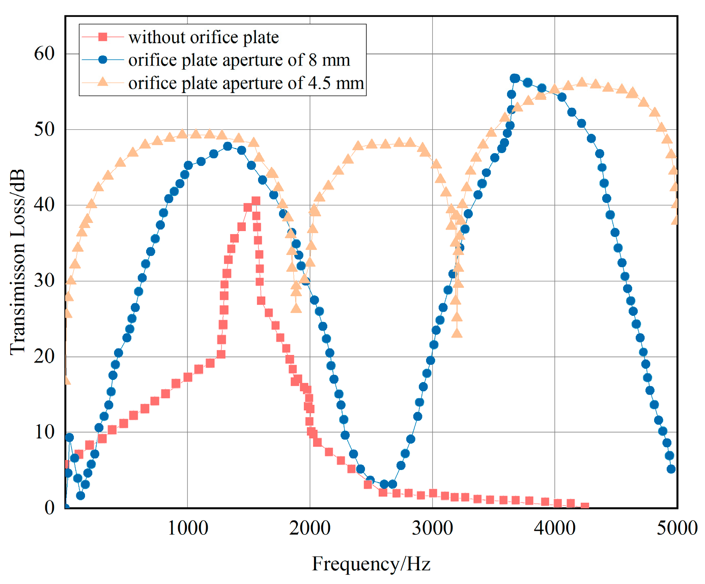
The transfer loss curves for the three cases are obtained via Matlab software 2018 as shown in Figure 9.
As shown in Figure 9, the transfer loss curve of the inverted bucket steam valve without an orifice plate exhibits only one peak (40.51 dB) in the frequency range of 0–2000 Hz. In contrast, after adding the 8 mm aperture orifice plate, the curve shows two peaks, with a maximum transmission loss of 58 dB. Meanwhile, the curve displays three peaks when the 4.5 mm aperture orifice plate is used, and the maximum transmission loss is 54 dB. The average value of the transmission loss of steam valves with different aperture plates is larger than that of steam valves without aperture plates, which indicates that the noise reduction effect has been greatly improved in this frequency interval. Between 2000 Hz and 5000 Hz, the average value of the transmission loss of the steam valve without an orifice plate is 20.16 dB, the average value of the transmission loss after an 8 mm aperture plate is 29.24 dB, and the average value of the transmission loss after a 4.5 mm aperture plate is 42.06 dB. In terms of the frequency range covered by the troughs, it shows that the acoustic performance of the inverted bucket steam valve is even better with the addition of noise-reducing orifices, and that noise-reducing elements with different structural parameters produce different noise-reducing effects.
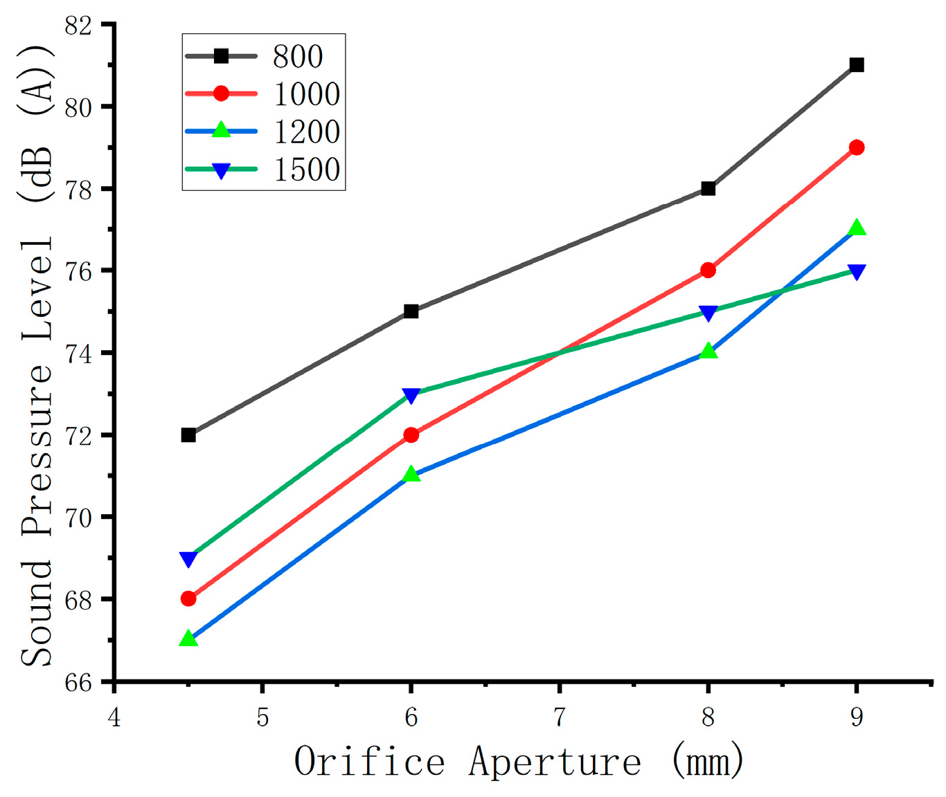
Figure 10 shows that the reduction in aperture shifts the main peak of noise to high frequency, but the sound pressure level is significantly reduced. The optimal range of 4.5–5 mm has a sound pressure level below 70 dB(A) in the sensitive frequency band of human ear of 1000–2000 Hz, and the noise reduction effect is significant.

4.4. SVM Approximate Modeling of Noise Reduction Structures for Inverted Bucket Steam Valve

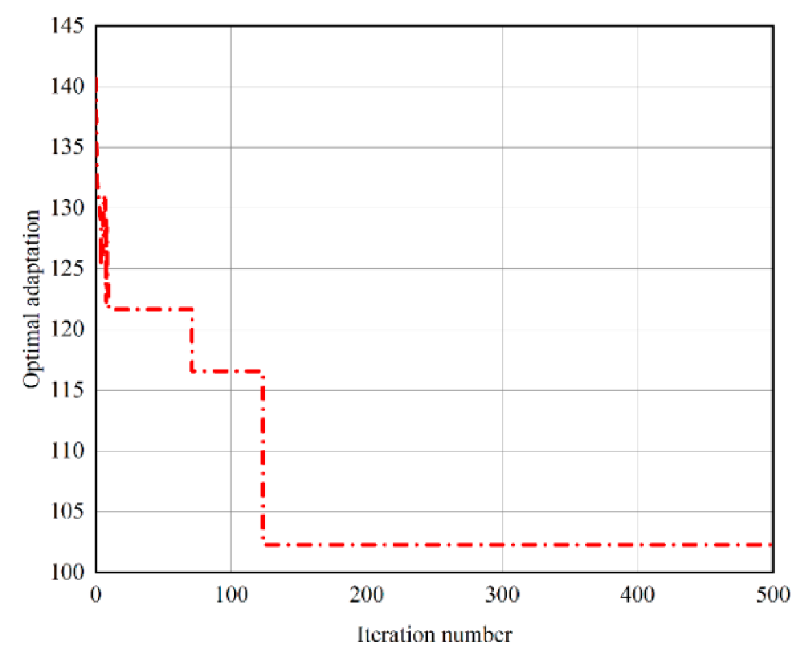
Out of 30 sets of data, 26 sets of data are extracted as input samples using the Latin hypercube sampling method, and after acoustic simulation is carried out, respectively, the transmission loss is extracted as output samples to form the training sample data set of the support vector machine, and the data of the training samples are normalized and imported into the support vector machine to carry out the training; the NOA genetic algorithm is used to optimize the kernel parameter, the insensitive loss parameter, and the penalty factor C optimization. The optimization results of the SVM parameters of the noise reduction structure are shown in Figure 10. From Figure 11, the optimal fitness converges after 106 generations, and the model root-mean-squared error MSE = 7.1821 × 10⁻⁵, penalty factor C is 115.512, nuclear parameter γ =0.036192, and insensitive loss parameters ε = 6.1951 × 10⁻⁴.
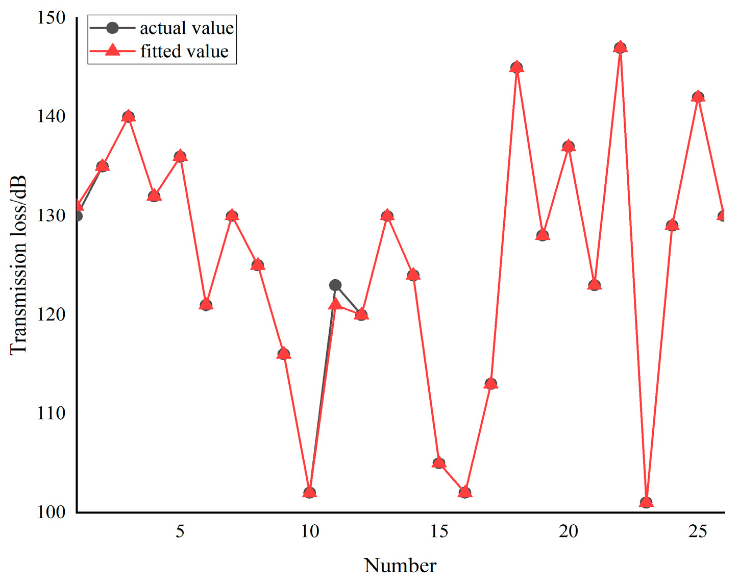
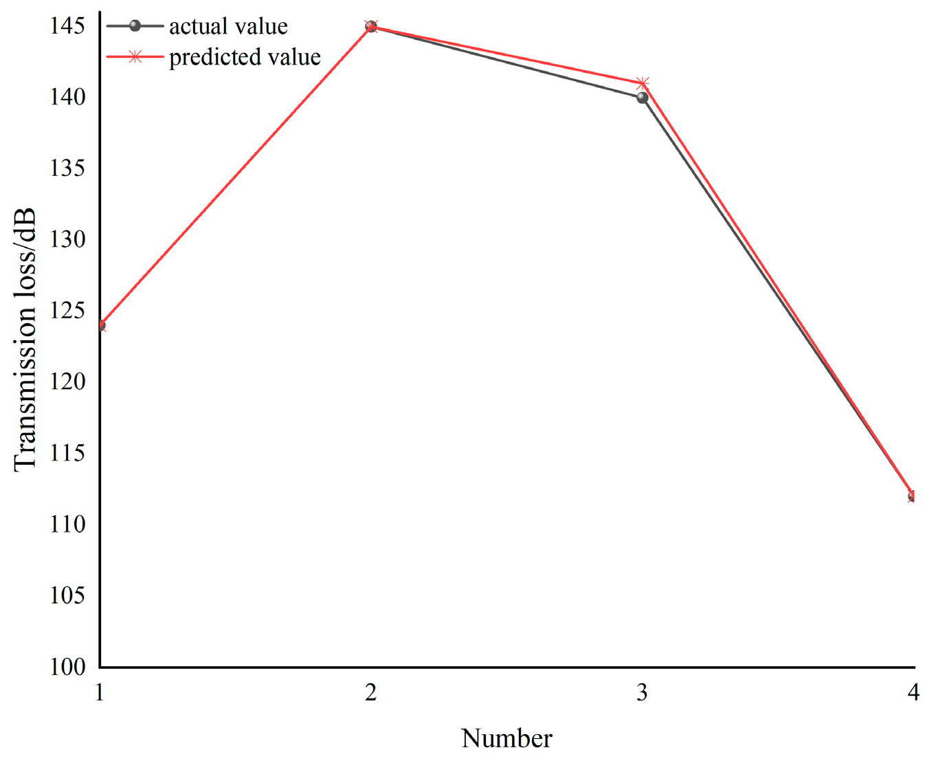
The SVM model for the maximum transmission loss of the inverted bucket steam valve is obtained by using the above optimized SVM parameter training. In order to check the fitting accuracy of the approximation model, Latin hypercubic sampling is used and then four groups of design variables are randomly selected to obtain the support vector machine test set, and the predicted values of the approximation model are compared with the calculated values of the numerical simulation, as shown in Figure 12 and Figure 13. The complex correlation coefficients of the fitted curves for the training set are calculated as R2 = 0.99942 and test set prediction curve complex correlation coefficient R2 = 0.99954. The test set data with a relative error of 0.2% indicates that the support vector machine approximation model f′(x) for the maximum transfer loss of inverted bucket steam valves has a high fitting accuracy and can predict the maximum transfer loss value of inverted bucket steam valves well.
The optimal set of solutions for SVM-NOA optimization of inverted bucket steam valves with a maximum transfer loss is calculated as the diameter of the hole is 4.521 mm, the drilling distance is 9.052 mm, and the plate thickness is 9.352 mm.

5. Acoustic Performance Testing

5.1. Test Bench Construction

An acoustic test study was conducted on the inverted bucket steam valve before and after optimization. The test bench is arranged in a semi-quiet room, close to the acoustic conditions of open space, and the test rig is shown in Figure 14.
A KSI-308A213 precision free field microphone is selected for the experiment. The Ksi-308a213 precision free field microphone and the vibration and noise test equipment have good amplitude frequency and phase frequency matching characteristics, which can ensure high accuracy and accuracy of the experimental data. A Dewesoft Sirius series 8-channel ultra-high dynamic acquisition instrument is selected, and each channel has two amplifiers and ads. They can avoid false frequency caused by noise in signal measurement, and the error is ±0.1%. In the dynamic range of up to 150 dB, the data of up to 1 ms/s can be obtained. The bandwidth is close to Nyquist’s law and can be used for frequency domain analysis of signals such as sound and vibration. The test will carry out “indoor reflection correction” on the collected sound pressure signal, measure the sound source direction through the microphone array, eliminate the sound energy component reflected by the wall, and only retain the direct sound; the microphone and acquisition instrument are calibrated before the test to ensure that the measurement accuracy matches the acoustic accuracy calculated by the model.
Two microphones are installed at both the 1D upstream and 3D downstream sections of the orifice plate, forming an “incidence-transmission” dual monitoring surface. The upstream section employs a non-directional sound source to generate broadband noise (20–5000 Hz), while the downstream section features acoustic absorption termination to prevent reflection interference. Spectrum analysis is performed using DEWESoft SIRIUS software 2022, employing the “transmission matrix method” to separate incident and transmitted acoustic power. The TL value is calculated through three repeated measurements under each aperture condition, with the average result serving as the final output.

5.2. Acoustic Performance Testing of Inverted Bucket Steam Valves

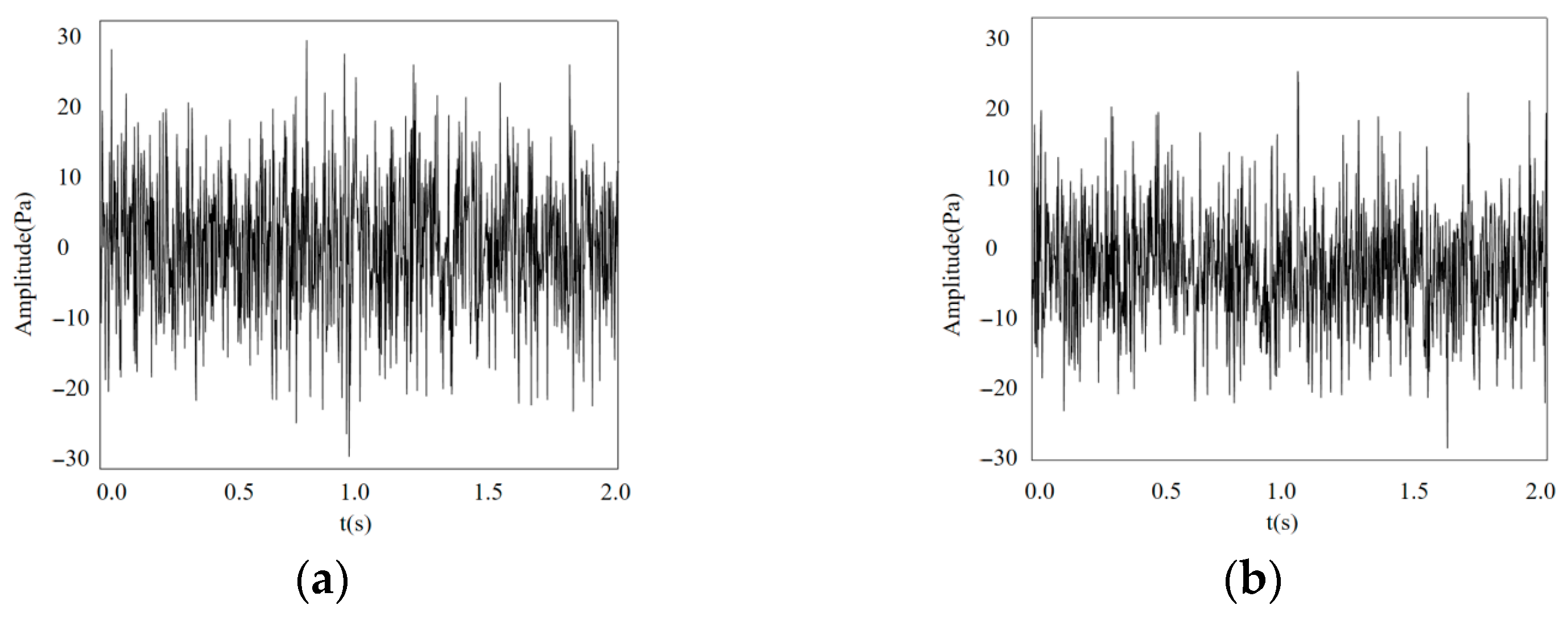
The test platform, with a start frequency of 10 Hz, a termination frequency of 5000 Hz, a step size of 20 Hz, and a sampling frequency of 20,000 Hz, is used to test the inverted bucket steam valve before and after optimization, and after noise reduction by Matlab software, the frequency and time domain data under different working conditions from 0 to 2 s are obtained, as shown in Figure 15. The acquired acoustic signals were converted into transfer loss to obtain the change in transfer loss under testing, as shown in Figure 16.
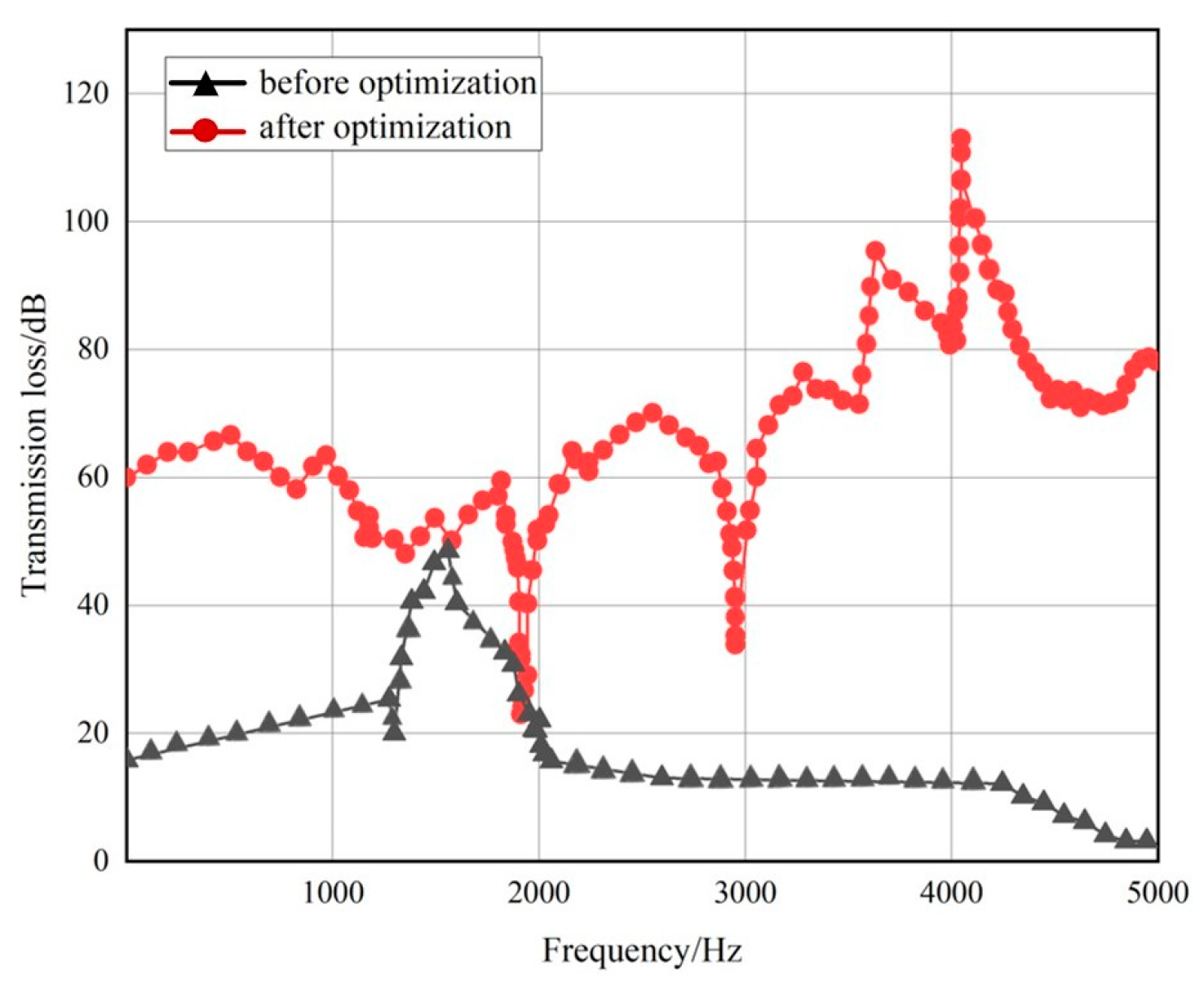
Comparing the transfer loss curve of the un-orifice plate in Figure 9 and the transfer loss curve of the test before optimization in Figure 16, it can be concluded that the trend of the transfer loss curve is basically the same, and the error is less than 3%, which proves the accuracy of the numerical simulation method.
From Figure 16, there is only one peak value of transmission loss in the inverted bucket type steam valve without an orifice plate, and the maximum transmission loss of the inverted bucket type steam valve without an orifice plate is 50.1 dB, with only one peak value; after the addition of the improved orifice plate, the peak value of the transmission loss becomes six, the maximum transmission loss is 116.21 dB, and the average value of transmission loss is listed in Table 6, indicating that SVM-NOA can be used to optimize the noise reduction structure of the inverted bucket type valve. Table 6 shows the average values of transmission loss before and after the improvement, indicating that SVM-NOA can be used to optimize the noise reduction structure of inverted bucket steam valves.
From Table 6, the test data are slightly higher than the simulation data due to the influence of the test environment and test equipment errors, but the overall error is less than 3%, which verifies the acoustic numerical simulation accuracy.

6. Conclusions

In the paper, the support vector machine approximation model is established instead of acoustic numerical simulation. and combined with the improved nutcracker optimization algorithm to optimize the structure of the noise reduction element inside the inverted bucket steam valve. The best structural parameters are obtained according to the optimization results, and the accuracy of the numerical simulation is verified through experiments. The specific conclusions are as follows:
Based on the NOA, an improved NOA is proposed. According to the numerical simulation theory of multi-physical field coupling, the SST k-ԑ model is used in the steady-state calculation stage, the LES turbulence model is used in the unsteady state, and the acoustic software is combined to study the acoustic performance of the inverted bucket steam valve in three different cases, respectively. The maximum transmission loss of the steam valve without the noise-reducing orifice plate is 40.51 dB. After adding the 8 mm orifice plate, the peak value is two and the maximum transmission loss is 58 dB. After adding the 4.5 mm orifice plate, the peak value becomes three and the maximum transmission loss is 54 dB.
Based on the SVM algorithm, the maximum transmission loss approximation model of the inverted bucket steam valve is established and, through comparison with the numerical simulation results, it is proven that the model has high prediction accuracy with a relative error less than 3%.
The acoustic performance of the inverted bucket steam valve before and after optimization is tested by means of experiments. The difference between the numerical simulation and experimental results of the inverted bucket steam valve without the orifice plate and with the improved orifice plate is less than 3%, which verifies the accuracy of the numerical simulation and provides theoretical guidance for the optimization of the valve control system for noise reduction.
The study has certain limitations: Firstly, the experimental verification is only applicable to the PN40 DN100 inverted bucket steam trap model and does not cover a wider range of nominal pressure, diameter, and supercritical conditions. The universality of the model needs further verification. Secondly, the noise reduction components only focus on the aperture, spacing, and thickness parameters of the orifice plate, without considering the influence of other structures such as porous materials and non-circular holes on the noise reduction effect and without in-depth analysis of the high-frequency noise suppression mechanism coupling between the orifice plate and the flow field inside the valve. Thirdly, the prediction accuracy of the SVM approximation model slightly decreases in the high-frequency range (>4000 Hz), which may be related to the simplification of the turbulence noise coupling law in this frequency band.
Future research can be conducted from three aspects: firstly, expanding experimental conditions to cover different specifications of drain valves and extreme conditions (such as high temperature and high pressure), to verify the applicability of the model; secondly, exploring the optimization design of composite noise reduction structures (such as orifice plates and sound-absorbing materials), and deepening the analysis of noise reduction mechanisms by combining fluid structure coupling theory; thirdly, introducing deep learning models (such as CNN-LSTM) to improve the accuracy of high-frequency noise prediction, and developing a fast optimization tool for noise reduction structural parameters for engineering applications.
Author Contributions

S.L.: Conceptualization, Methodology; Y.W.: Methodology, Writing—original draft preparation, Writing—review and editing; D.L.: Writing—review and editing; W.L.: Methodology, Writing—review and editing; Y.T. and J.W.: Supervision. All authors have read and agreed to the published version of the manuscript.

Funding

The authors received no funding to complete this research.

Institutional Review Board Statement

Not applicable.

Informed Consent Statement

Not applicable.

Data Availability Statement

Data are available on request from the authors.

Conflicts of Interest

On behalf of all authors, the corresponding author declares that they have no known competing financial interests or personal relationships that could have appeared to influence the work reported in this paper.

References

  1. Chen, F.; Jin, Z. Numerical analysis of thermal stresses in high-parameter pressure reducing valves containing porous plates. Adv. Chem. Eng. 2019, 38 (Suppl. S1), 19–26. [Google Scholar] [CrossRef]
  2. Zhou, Z.; Wu, J. Study on the performance of micro-perforated plate absorber under coupling. Ship Mech. 2021, 25, 828–841. Available online: https://webofscience.clarivate.cn/wos/alldb/full-record/CSCD:6993744 (accessed on 6 November 2025).
  3. Li, S.; Kang, Y.; Wang, T.; Pan, W.; Li, C. Numerical simulation study of jet flow characteristics of a reduced pressure sleeve throttling orifice plate of a valve regulator valve. Fluid Mech. 2019, 47, 19–26. [Google Scholar] [CrossRef]
  4. Su, H.; Yang, G.; Zhang, L.; Chen, P.; Li, R. Analysis and optimization of fluid vibration noise of fuel dispenser relief valve. Vib. Shock. 2013, 32, 130–134. [Google Scholar] [CrossRef]
  5. Jiang, W.; Zhang, H.; Meng, K. Research on the flow noise of underwater submarine based on boundary element method. Hydrodyn. Res. Prog. Ser. A 2013, 28, 453–459. [Google Scholar] [CrossRef]
  6. Li, H.; Guo, H. Exploration on Aerodynamic Noise Characteristics for Control Valve of Steam Turbine. Appl. Mech. Mater. 2012, 224, 395–400. Available online: https://webofscience.clarivate.cn/wos/woscc/full-record/WOS:000316308700083 (accessed on 6 November 2025).
  7. Meng, L.; Liu, C.; Li Wang, W.; Zhang, F. Pneumatic Noise Generation Mechanism of Gas Transmission Pipeline and Its Analysis Method. J. China Univ. Pet. (Nat. Sci. Ed.) 2012, 36, 128–136. [Google Scholar] [CrossRef]
  8. Zhang, T.; Lai, H. Shape modification and noise control of minimum flow circulation valve outlet of nuclear power boiler feedwater pump. J. East China Univ. Sci. Technol. (Nat. Sci. Ed.) 2015, 41, 396–402. [Google Scholar] [CrossRef]
  9. Yang, M.; Vicente, R.G. Subwavelength Broadband Perfect Absorption for Unidimensional open-Duct Problems. Adv. Mater. Technol. 2023, 8. [Google Scholar] [CrossRef]
  10. Xu, C.; Wang, J.; Wang, J.; Chang, A. Application of particle swarm optimization algorithm in the design of micro-perforated plates for noise reduction structures in rail transit. J. Northwest Univ. (Nat. Sci. Ed.) 2016, 46, 33–37. [Google Scholar] [CrossRef]
  11. Nie, T.; Yang, K.; Zhou, L.; Wu, X. Structural optimization of high-speed high-flow solenoid valve based on genetic algorithm. J. Nav. Eng. Univ. 2022, 34, 60–65. [Google Scholar] [CrossRef]
  12. Xie, H.; Hong, H.; Wang, B.; Jiang, W.; Yang, H. Optimized design of axial piston pump low pulsation structure based on multi-objective genetic algorithm. J. Eng. Des. 2024, 1–9. Available online: https://link.cnki.net/urlid/33.1288.th.20240219.1647.006 (accessed on 6 November 2025).
  13. Ji, G.; Sun, T.; Liu, J.; Tang, J.; Wang, J.; Hu, X. Structural Optimization Design of Dual Robot Gripper Unloading Device Based on Intelligent Optimization Algorithms and Generative Design. Sensors 2023, 23, 8298. [Google Scholar] [CrossRef] [PubMed]
  14. Malihe, J.; Eysa, S.; Javad, S. Optimal design of truss structures using a hybrid method based on particle swarm optimizer and cultural algorithm. Structures 2021, 32, 391–405. [Google Scholar] [CrossRef]
  15. Chen, D.; Han, J.; Zhong, J. Investigation of optimization design of partial admission turbine. J. Eng. Thermophys. 2020, 41, 829–839. Available online: https://webofscience.clarivate.cn/wos/alldb/full-record/CSCD:6691811 (accessed on 6 November 2025).
  16. Xu, K.; Wang, G.; Zhang, L.; Wang, L.; Yun, F.; Sun, W.; Chen, X. Multi-Objective Optimization of Jet Pump Based on RBF Neural Network Model. J. Mar. Sci. Eng. 2021, 9, 236. [Google Scholar] [CrossRef]
  17. Nouhi, B.; Jahani, Y.; Talatahari, S.; Gandomi, A.H. A swarm optimizer with modified feasible-based mechanism for optimum structure in steel industry. Decis. Anal. J. 2022, 5, 100129. [Google Scholar] [CrossRef]
  18. Zhu, C.; Duan, S. Optimal design of composite panel structure noise using response surface method. Noise Vib. Control. 2023, 43, 92–97. Available online: https://nvc.sjtu.edu.cn/CN/Y2023/V43/I2/92 (accessed on 6 November 2025).
  19. Zhang, X.; Lai, X.; Chen, X.; Liu, S. Optimization study of impeller performance of high-speed centrifugal pump based on PB-NSGA-III algorithm. Electromech. Eng. 2023, 40, 1948–1956. [Google Scholar] [CrossRef]
  20. Jin, X.; Cheng, P. Prediction model of velocity field around circular cylinder over various Reynolds numbers by fusion convolutional neural networks based on pressure on the cylinder. Phys. Fluids 2018, 30, 047105. Available online: https://webofscience.clarivate.cn/wos/woscc/full-record/WOS:000431138700017 (accessed on 6 November 2025). [CrossRef]
  21. Mohamed, A.-B.; Reda, M.; Mohammed, J.; Mohamed, A. Nutcracker optimizer: A novel nature-inspired metaheuristic algorithm for global optimization and engineering design problems. Knowl.-Based Syst. 2023, 262, 110248. [Google Scholar] [CrossRef]
  22. Wu, D.; Zhou, Q.; Wen, L. Improved sparrow algorithm based on logistic chaotic mapping. J. High. Educ. Sci. 2021, 41, 10–15. [Google Scholar] [CrossRef]
  23. Ma, D.; Li, P.; Mu, X.; Wang, H. Flow and noise characteristics of small-aperture mufflers. J. Acoust. 1984, 9, 273–281. Available online: https://link.cnki.net/doi/10.15949/j.cnki.0371-0025.1984.05.001 (accessed on 6 November 2025).
Figure 1. Algorithm flow chart.
Acoustics 07 00074 g001
Figure 2. Inverted bucket steam valve model structure.
Acoustics 07 00074 g002
Figure 3. Inverted bucket steam valve model at different apertures. (a) Orifice plate aperture of 4.5 mm; (b) orifice plate aperture of 8 mm.
Acoustics 07 00074 g003
Figure 4. Flow field transient pressure diagram. (a) Without orifice plate; (b) orifice plate aperture of 8 mm; (c) orifice plate aperture of 4.5 mm.
Acoustics 07 00074 g004
Figure 5. Flow field transient velocity diagram. (a) Without orifice plate; (b) orifice plate aperture of 8 mm; (c) orifice plate aperture of 4.5 mm.
Acoustics 07 00074 g005
Figure 6. Spherical sound field grid.
Acoustics 07 00074 g006
Figure 7. Pressure pulsation cloud at typical frequency. (a) Without orifice plate; (b) orifice plate aperture of 8 mm; (c) orifice plate aperture of 4.5 mm.
Acoustics 07 00074 g007
Figure 8. Cloud view of sound pressure distribution at peak frequency. (a) Without orifice plate; (b) orifice plate aperture of 8 mm; (c) orifice plate aperture of 4.5 mm.
Acoustics 07 00074 g008
Figure 9. Transmission loss curves at three conditions.
Acoustics 07 00074 g009
Figure 10. Sound pressure level at different aperture peak frequencies.
Acoustics 07 00074 g010
Figure 11. Approximation model iterative curve of SVM.
Acoustics 07 00074 g011
Figure 12. Training set comparison results.
Acoustics 07 00074 g012
Figure 13. Prediction set comparison results.
Acoustics 07 00074 g013
Figure 14. Test platform.
Acoustics 07 00074 g014
Figure 15. Time-frequency domain data in different conditions. (a) Before optimization; (b) after optimization.
Acoustics 07 00074 g015
Figure 16. Frequency-dependent transmission loss curves of an inverted bucket steam trap before and after optimization.
Acoustics 07 00074 g016
Table 1. Design variable value intervals.
VariantAperture/mmHole Spacing/mmThickness of Orifice Plate/mm
Original design value5610
Optimizing the upper bound4.55.59.5
Optimize the lower bound8916
Table 2. Grid irrelevance verification.
Grid SchemeNumber of Grid CellsNumber of NodesMass Flow kg/s
Option 1825,314155,2141.20
Option 2827,311163,3511.21
Option 3828,344166,3741.23
Table 3. Comparison group with different apertures.
Serial NumberApertureHole SpacingThickness of Orifice Plate
14.559
2559
35.559
4659
56.559
6759
77.559
8859
98.559
10959
Table 4. Comparison group with different hole spacing.
NumberApertureHole SpacingThickness of Orifice Plate
14.55.59
24.569
34.56.59
44.579
54.57.59
64.589
74.58.59
84.599
94.59.59
104.5109
Table 5. Comparison group with different thickness of orifice plate.
NumberApertureHole SpacingThickness of Orifice Plate
14.559
24.5510
34.5511
44.5512
54.5513
64.5514
74.5515
84.5516
94.5517
104.5518
Table 6. Comparison of simulated and experimental mean values of transmission loss.
FrameworkMean Value of Transmission Loss Obtained from Simulation/dBMean Value of Transmission Loss Obtained from the Test/dBInaccuracy/dB
Before optimized20.5020.77+0.27
After optimized63.4564.91+1.46
Disclaimer/Publisher’s Note: The statements, opinions and data contained in all publications are solely those of the individual author(s) and contributor(s) and not of MDPI and/or the editor(s). MDPI and/or the editor(s) disclaim responsibility for any injury to people or property resulting from any ideas, methods, instructions or products referred to in the content.