
Generation of a Multi-Scale Historic BIM-GIS with Digital Recording Tools and Geospatial Information


1
Department of Architecture, Built Environment and Construction Engineering (ABC), Politecnico di Milano, Via Ponzio 31, 20133 Milan, Italy
2
Polo Territoriale di Lecco, Politecnico di Milano, Via Previati 1/c, 23900 Lecco, Italy
*
Author to whom correspondence should be addressed.
Heritage 2021, 4(4), 3331-3348; https://doi.org/10.3390/heritage4040185
Submission received: 1 August 2021
/
Revised: 9 September 2021
/
Accepted: 8 October 2021
/
Published: 12 October 2021
Abstract
:This paper discusses the creation of an integrated historic BIM-GIS for the complex of San Pietro al Monte, an important Romanesque monument in Civate (Italy) inscribed in the UNESCO tentative list with other seven medieval Benedictine settlements. The reason behind the choice of an integrated H-BIM-GIS solution is motivated by the large extension of the considered area (about 30 km2) and the need for multi-scale digital information integrated into a 3D parametric environment. The model includes geospatial information at a territorial scale and in situ digital data capturing the complex at a higher level of detail. The work aims at exploring the pros and cons of a novel parametric 3D environment able to integrate both BIM and GIS data, methods, and processing tools in the case of historic buildings and sites.
1. Introduction
In recent years, Building Information Modeling (BIM) has gained progressive importance for heritage documentation. HBIM (Historic BIM) was described by [1,2] considering the case of historic buildings, notwithstanding that parametric modeling from laser scans had already been proposed by the same authors in [3].
Historic buildings feature additional problems compared to more regular modern buildings. Different authors have proposed different procedures and methods to generate accurate HBIM for different typologies of historic constructions, such as churches and cathedrals, villas and palaces, castles, and bridges, among others [4,5,6,7,8,9].
Digital recording methods such as laser scanning and photogrammetry [10] are often used to capture accurate and dense point clouds that can guide the modeling phase in BIM software. Point clouds are then used to model the different constructive elements of the building using a parametric approach. Different authors have developed procedures and solutions for the creation of an accurate BIM starting from a photogrammetric and laser scanning survey. The reader is referred to [11,12,13,14,15] for some examples.
Most software (Autodesk Revit, ArchiCAD, etc.) capable of creating a parametric model based on BIM tools was developed considering modern constructions. The model is generated by assembling different constructive elements (floors, walls, stairs, doors, windows, etc.). As historic constructions often feature very irregular geometry, research work has been conducted to develop methods to provide a parametric representation of complex geometries, minimizing the loss of geometric accuracy in the transition from the point cloud to the BIM.
This paper aims at implementing a multi-scale BIM approach different than the traditional BIM process, which mainly concentrates on the level of the building. The case study described in the manuscript has a much wider extension and covers a geographic area of about 5 km × 6 km. The paper, therefore, investigates the opportunity to generate a parametric model not limited to the level building, but also at a cartographic level with the integration of GIS information [16].
The considered case study is the complex of San Pietro al Monte (Civate, Italy) an important Romanesque monument located on mount Cornizzolo (Figure 1). The complex consists of three buildings: the Basilica of San Pietro, the Oratory dedicated to San Benedetto, and some ruins of the monastery. The complex was presumably founded during the first centuries of the Middle Ages. It was largely renewed in the 11th century when religious settlements gained power. The abbey was repeatedly abandoned over the centuries. A large part of the monastery collapsed, and few remains are still visible. The main church was restored during the 19th and 20th centuries. Since 2016, San Pietro al Monte is included in the UNESCO Tentative List in the framework of the project “The cultural landscape of the Benedictine settlements in medieval Italy”.
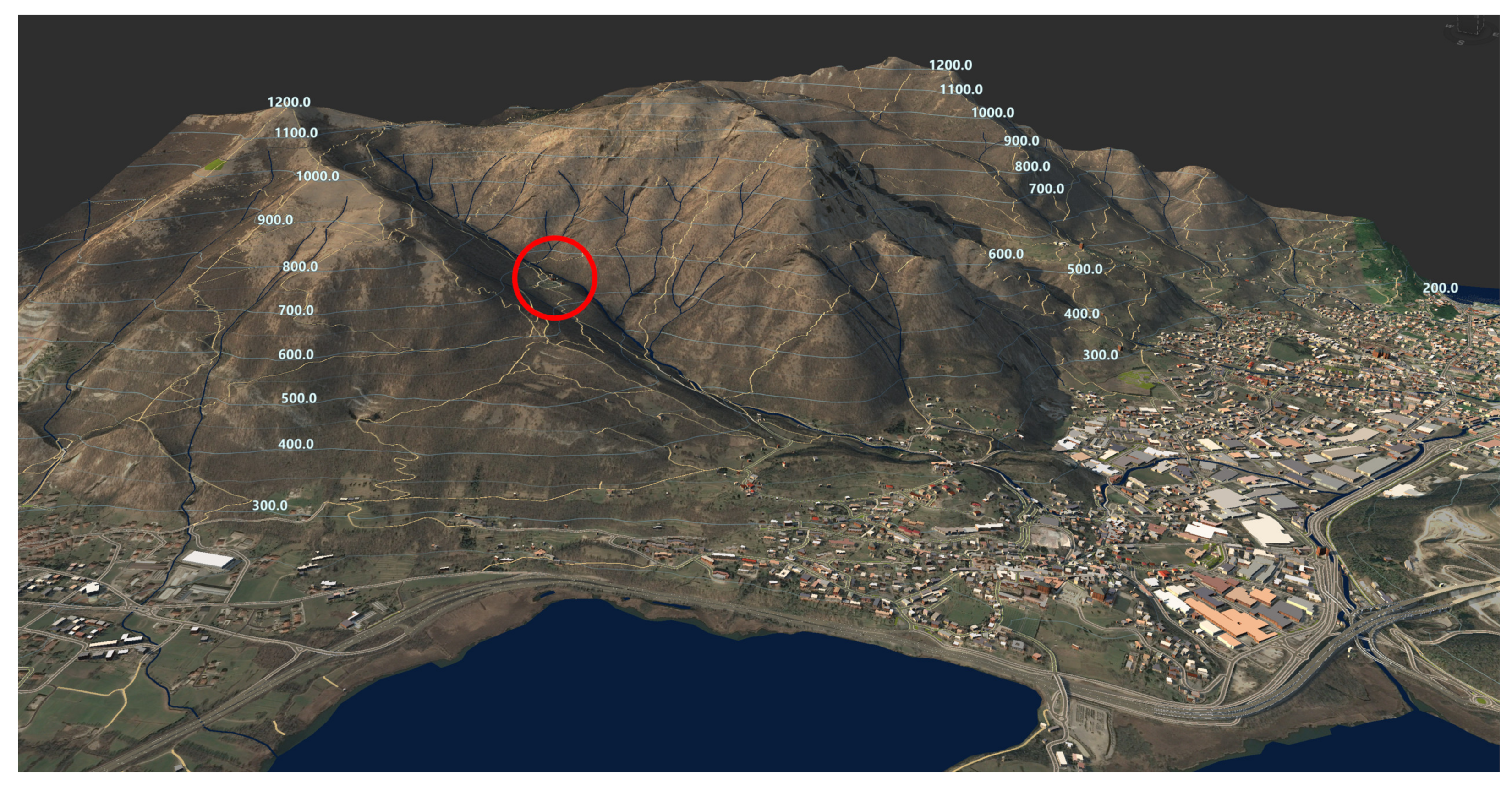
The considered area with a preliminary version of the initial BIM-GIS model is shown in Figure 2. The model is made up of different datasets: digital terrain model and contour lines, orthophoto, building layer, road network, and water areas. The location of the complex is marked with a red circle. The multi-scale H-BIM-GIS here proposed integrates georeferenced information and combines parametric modeling tools of BIM that can also operate on cartographic information. However, the traditional BIM objects (e.g., floors, walls, doors, windows, etc.) are not considered in this work. The BIM-GIS uses objects like buildings, roads, water bodies, vegetation, etc., and offers a 3D environment with parametric modeling tools that are usually used for infrastructure [17,18]. Indeed, infrastructure projects often cover a field that spans from the local level to the cartographic scale [19], requiring specific local data georeferenced in a cartographic reference system as well as geospatial information at different levels (e.g., municipality, provincial, regional, or national level).
2. Overview of the Proposed H-BIM-GIS
The choice behind the development of a multi-scale H-BIM-GIS system not limited to an HBIM is motivated by the intrinsic characteristics of the site. The complex of San Pietro al Monte can be reached through a mountain path of about 2.5 km in length, with a difference in elevation of about 400 m from the bottom of the valley. The path and the surrounding area in the municipality of Civate have several historic sites that cannot be neglected in the creation of a comprehensive digital database. For instance, the Casa del Pellegrino and other churches (S. Vito, S. Calocero al piano, S. Nazzaro e Celso) were also considered in the development of the integrated H-BIM-GIS.
The study was undertaken using two commercial software programs that can exchange digital data: Autodesk InfraWorks and ArcGIS Pro. The extension of the area and the availability of multi-source information collected for more than ten years required an environment able to store and make available heterogeneous datasets. The authors’ choice was an H-BIM-GIS with a variable detail from the cartographic level to the different buildings here considered and their constructive elements.
The proposed BIM-GIS approach is:
- multi-scale: from the territorial scale to the architectural details of the complex;
- multi-sensor: different methods and tools were used to capture the geometric data necessary for the modeling work;
- multi-temporal: data were acquired in different years and can also be used to find changes that occurred over time.
The idea was the creation of a digital environment able to integrate georeferenced information in the UTM 32-WGS84 (ETRF2000) system [24] in a way that is easily accessible and can be exploited for several applications not only limited to the context of the abbey. The data feature variable resolutions and formats for which the single-use of only a single software program is not sufficient.
Figure 3 shows the concept behind the development of the proposed digital environment. Geospatial data in both raster and vector formats [25] were retrieved from different online repositories that provide open data at the provincial and regional levels. Information from OpenStreetMap was also imported, as well as multi-temporal satellite images (Sentinel-2 and Landsat) [26]. Different surveying campaigns (in situ) were carried out on-site for about ten years. Digital images and laser scans were captured using different platforms (drones, terrestrial cameras, laser scanners, 360 cameras, etc.) to produce various deliverables such as 3D models, measured drawings, orthoimages, and digital elevation models, which were integrated for the first time into a single 3D environment.
InfraWorks allows the user to import such a variety of digital records directly if georeferencing information is available. For this reason, a solution was also developed for those products that are not georeferenced. For instance, orthophotos of vertical elevations have an associated georeferenced point-of-interest (POI) in the system so that the user can select the (POI) and get access to the image.
3D models, DEMs, orthophotos in the cartographic plane (East, North), and point clouds can instead be directly imported using georeferencing information. The elevation used during the creation of the model is the orthometric elevation (H) [27]. The conversion from ellipsoid elevation (h) was carried out using the Italian geoid model ITALGEO2005 [28]. When measurements cover a large area (such as the 30 km2 considered in this work) the digital environment must be able to cope with cartographic reference systems. The use of a traditional Cartesian reference system (X, Y, Z) would not able to handle the different effects, such as the curvature of the Earth [29].
The proposed H-BIM-GIS also covers an intermediate level between cartographic applications and the architectural scale. It can operate and communicate with both systems, which are still necessary for specific operations. In fact, the proposed solution does not replace GIS and BIM, which are still the best solutions depending on the problem to be solved. One of the goals of this work was to provide a better way to access information and coordinate processing instead of replicating those operations which can be carried out with GIS and BIM technology.
This work mainly concentrates on the simultaneous use of two applications that can communicate and dynamically transfer data: ArcGIS Pro (and ArcGis Online) and Autodesk InfraWorks. The combined use of both software packages has the great advantage of enabling different types of operations, thereby combining BIM and GIS functionalities. Interoperability can be obtained with static file transfer (e.g., import/export tools) or in a more dynamic way with the Autodesk Connector for ArcGIS available in InfraWorks. The main disadvantage of the proposed solution is the need for two different software platforms. However, as also mentioned in other work [30], the aim of this work is not the development of an alternative approach based on a single environment, but to use both technologies (BIM and GIS) and cope with their reciprocal pros and cons (Figure 4). The simultaneous use of BIM and GIS allows the reimplementation of tools already available in a specific package. From this point of view, interoperability becomes an essential requirement because it allows for the movement of data and the production of new information without duplicating existing functions and tools already available in one of the two types of software used.
Autodesk Connector for ArcGIS allows improved interoperability between InfraWorks and ArcGIS. Data processed in ArcGIS Pro and uploaded in ArcGIS Online as well as data directly generated in ArcGIS Online can be retrieved and imported in InfraWorks after setting the extension of the project area. All data sources uploaded and made available by the user along with data accessible in ArcGIS Online become visible in Connector. The user only has to select the data source and define the typology of the object (e.g., building, road, water body, etc.) to add georeferenced datasets in the project. A dataset in InfraWorks can also be published into ArcGIS Online, adding specific tags to simplify search and discovery operations. On the other hand, limitations were found for some specific file formats that cannot be dynamically exchanged through Connector and that required a more traditional import/export approach based on files readable by the two software platforms.
3. The Model Based on Geospatial Information at a Territorial Scale
3.1. Creation of the Preliminary Cartographic Model
A preliminary BIM-GIS of the considered area of about 30 km2 was generated using the Model Builder tool available in InfraWorks, which creates a 3D model in a fully automated way after defining the boundary of the area. Model Builder can retrieve the following types of geospatial information available in different online repositories:
- buildings from OpenStreetMap;
- roads and railways from OpenStreetMap;
- digital elevation models as 10 m × 10 m or 30 m × 30 m gridded files. The resolution depends on the location. Terrain data for the United States and its territories have a 10 m DEM resolution. The area between −60° and +60° latitude is covered by the SRTMGL1 30 m DEM data. The area between +60° and +83° latitude uses ASTER GDEM v2 30 m DEM data;
- satellite imagery from Microsoft® Bing Maps, which is automatically draped over the DEM;
- water bodies as vector layers from the OpenStreetMap dataset.
The result and some details are visible in Figure 5. The preliminary model was saved as proposal 1 (p1). Indeed, InfraWorks allows users to generate multiple proposals in the same project, which aims at showing different design alternatives for the different modules (such as road design).
The opportunity to keep multiple proposals was used to produce models with a progressively refined level of detail without losing important information when additional products are available. From this point of view, the H-BIM-GIS model is a repository of digital information that exploits different combinations of digital information stored in different proposals which can be modified (such as deleting or merging existing proposals), offering statistical tools to quantify operations. For instance, the user can automatically retrieve the area occupied by buildings or the length of roads. For more advanced operations, the user can instead use the advanced geospatial processing tools available in ArcGIS, exploiting the concept of interoperability based on common formats and avoiding the reimplementation of tools already available.
3.2. Refining the Model with Additional Geospatial Information
A huge amount of open geospatial data is available in the considered area. An initial model generated automatically can be then integrated with additional files that can be available online in repositories not linked to Model Builder. In this way, a second proposal (p2) can be added to the project (Figure 6), without erasing the initial model (p1) that could be useful for other analyses.
A digital terrain model with a higher geometric resolution was added to the project. The DTM of the Lombardy Region is provided as a 5 m × 5 m grid. The DTM was produced using airborne LiDAR and filtering procedures to interpolate terrain points only. It is available as a GeoTIFF for the different provinces at no cost. The part related to the province of Lecco was downloaded from the Open Data Geoportal of the region, imported into ArcGIS and clipped to consider only the area of interest for the project. The DTM was then saved as a new GeoTIFF and imported into InfraWorks.
The resolution of the new DTM is significantly better than the preliminary solution based on Model Builder. One of the operations carried out was the reconstruction of the vertical profile of the path from the municipality of Civate to the abbey, which can be directly carried out in InfraWorks using the Road Design tool. Results are significantly more accurate than those based on the proposal 1 DEM.
Additional vector data were integrated into proposal 2. The geospatial database of the region contains multiple layers. In the case of the model shown in Figure 6, the GIS model includes buildings, roads, rivers streams, the lake, and green areas. Some layers were transferred to InfraWorks using Connector after sharing them on ArcGIS Online. Data retrieval and import into InfraWorks was automated and did not require duplication of data on the laptop used for the work because data sharing is carried out using cloud services. After importing a new feature layer into InfraWorks, it is necessary to define the typology of an object and its main parameters. In this way, parametric capabilities are added to the model that can be used for further processing using an approach like BIM.
4. Integration of In-Situ Digital Information
4.1. Georeferencing In Situ Data Using GNSS
A multi-scale approach was implemented starting from the cartographic level to the level of detail of the complex and its constructive elements. Indeed, the integrated BIM-GIS can store georeferenced data at different scales. The in situ digital surveys of the abbey were carried out using different techniques and methods.
Accurate georeferencing of metric information is a fundamental aspect to achieve an integrated platform encapsulating in-situ data. Measurements captured on-site were georeferenced using GNSS techniques based on Leica 1200 receivers, using a combination of static processing methods and Real-Time Kinematics [31]. Although a permanent GNSS network is available in the region [32], the internet connection close to the complex was not sufficiently strong to provide real-time transmission of differential corrections. The survey was conducted using a base receiver with approximated coordinates and a rover connected via radio. The master receiver also captured raw data for a long session (about 4 h) which was used to calculate precise base coordinates. RINEX data of the permanent GNSS station in the city of Lecco were used to estimate a baseline [33]. Lecco station is the closest GNSS receiver and is located about 7 km from the abbey.
Rover coordinates were then corrected accordingly. Ellipsoid elevations were converted into orthometric elevation using the geoid model ITALGEO2005. The expected precision of a survey conducted in this way is about ±2–4 cm, which is sufficient for georeferencing all the metric data acquired on-site. The use of the Italian geoid model ITALGEO2005 provides better results than global models available in most commercial software (e.g., EGM96).
If compared to traditional approaches for BIM generation, the use of georeferenced data is fundamental to ensure integration between cartographic data and cannot be neglected in the case of accurate digital recording projects. Total station measurements allowed the registration of the different laser scanning and photogrammetric projects on the GNSS points. The conversion from the local reference system of the total station (x, y) to the cartographic (East, North) based on UTM32-WGS84 (ETRF2000) was carried with a roto-translation, i.e., a three-parameter transformation estimated from common points, obtaining residuals in the order of ±1–2 cm. The calculation for the area of the complex did not include a scale factor to preserve the real distances of the total station and laser scanning measurements, which were used to create 3D models. In this way, the 3D model generated using laser scanning measurements provides effective distances more useful for conservation activities.
4.2. Laser Scanning and Photogrammetry with a Drone
A photogrammetric flight was carried out with a Parrot Anafi to produce a georeferenced orthophoto and digital elevation model of the area. A block of more than 200 images was processed with Agisoft Metashape, adding some control points (target placed on the ground) measured using GNSS techniques. Images were acquired using the Pix4D Capture application, which allowed the creation of an automatic flight plan with 80% longitudinal and 60% transversal overlap.
The flight was then integrated with some convergent images to reconstruct the vertical facades of the abbey and the baptistery. The solution was both automatic (using the circular acquisition tool in Pix4D Capture) and manual, i.e., manually controlling the drone to capture convergent images close to the trees. Figure 7 shows a georeferenced/textured 3D model of the exterior of the complex, which was imported as a mesh object into InfraWorks.
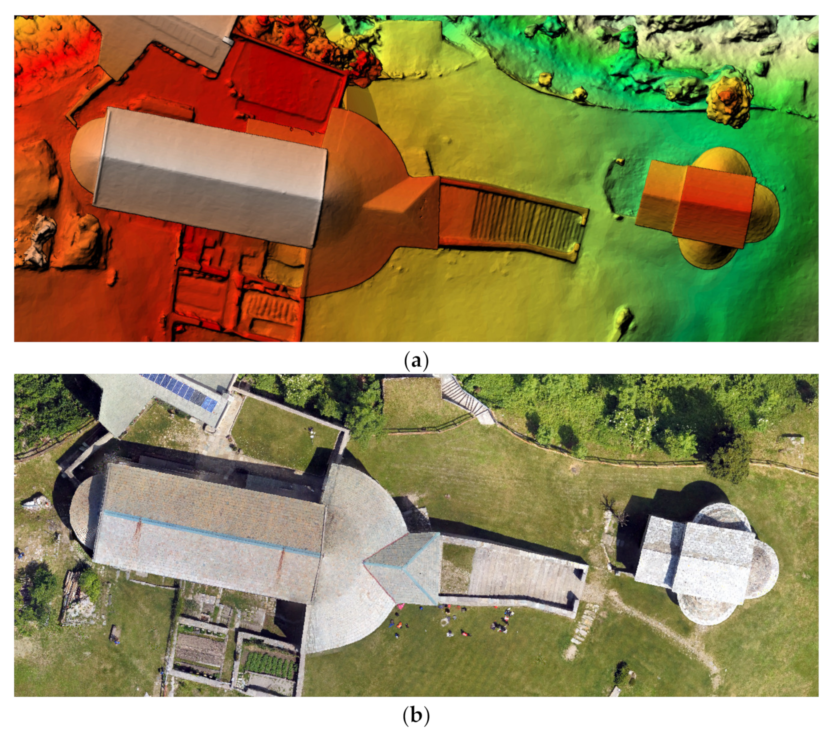
A digital elevation model and an orthophoto were also produced and integrated into both ArcGIS Pro and InfraWorks (as a new proposal n. 3, Figure 8). The centimeter-level resolution of the drone orthophoto and DEM enhanced project resolution of two orders of magnitude, notwithstanding that the covered area is limited to the complex. It is important to mention that the whole area considered also includes several other sites which are still not digitally documented, at least at a local level. However, integration of such additional sites in the same project is feasible and allows the user to create a single H-BIM-GIS with variable levels of detail in multiple locations stored in different proposals. Overall, the H-BIM-GIS must be intended as a dynamic environment where new information can be added not only limited to the considered complex, but also for other buildings and sites.
Additional images of the façade were captured with a frame camera Nikon D610 with a calibrated 35 mm lens. In this way, detailed orthophotos of the exterior elevations were created. Such images are not directly integrated into the BIM-GIS but are stored in a separate folder. A landmark is added to the BIM-GIS environment to indicate the availability of vertical orthophotos. The landmark file is a point ESRI shapefile in which the attribute table contains information about the storage folder. Points in ArcGIS are then parametrized as point-of-interest in InfraWorks.
A set of laser scans was also captured to support the creation of a 3D model, which was generated in Cinema 4D using a manual modeling approach. The 3D model was textured with photographs to obtain a photorealistic visualization. The manual model was generated using both simple (planes) and advanced surfaces based on NURBS (Non-uniform rational basis spline) to accurately model the surfaces of the complex without using heavy meshes. Both (manual) model and the georeferenced point cloud can be imported into InfraWorks.
4.3. Photogrammetry with 360° Spherical Images
360° images can be used not only for the photographic documentation of buildings and sites but also for photogrammetric applications and virtual reality. Previous work [34,35,36,37] demonstrated that a sequence of 360° images (also called spherical images, panoramas, or equirectangular projections) can be photogrammetrically processed to extract metric information. The spherical camera model is supported by different commercial software e.g., Agisoft Metashape or Pi×4D Capture. Data processing is based on a workflow like the more traditional processing of frame images (pinhole camera model), notwithstanding significant differences in both image acquisition, image matching and adjustment that must be considered. The process starts with the extraction and matching of corresponding points between the images, and the calculation of camera poses (exterior orientation parameters) and 3D point coordinates via bundle adjustment. The process continues with the generation of a dense point cloud, meshing and texture mapping, and orthophoto generation.
Spherical images are helpful tools when the spaces to be captured are closed rooms, or long and narrow spaces like corridors. A single 360° image can capture the entire space around the camera, reducing the number of images necessary to record the entire scene and the time required. Moreover, the camera can be pointed in any direction, facilitating data acquisition for operators. Disadvantages consist of the lower resolution and metric precision of the final model when compared to traditional photogrammetry with frame cameras, and the problems in controlling illumination conditions under an angle of 360° that does not guarantee uniform lighting.
The model can also reveal a variable level of details depending on camera-object distances as well as the geometry and number of images in which the object point is visible. Some parts can be captured by several images with favorable camera geometry and others could be visible only in a few images with weak camera geometry.
Spherical images were used to reconstruct the interior of the Basilica, including the crypt downstairs. Images were acquired with a Samsung 360°, which can capture stereo-pairs of front and rear images based on the fisheye camera model that are stitched to produce a single equirectangular projection. The use of some control points allowed us to georeference the extracted model and point clouds. Although metric accuracy cannot reach the results with a more traditional photogrammetric approach (the use of frame-based cameras), spherical photogrammetry provided a reconstruction with a limited set of images and short data acquisition and processing time.
In the case of the interior of the church (Figure 9, top), data acquisition required only less than 10 min. The processing time took only 3 h.
4.4. Photogrammetry with Fisheye Images
Some elements of the complex were captured with a higher level of detail using an image-based method based on fisheye photogrammetry [38,39]. Fisheye lenses offer wider fields of view than frame lenses, and they can be mounted on camera bodies featuring high geometric and radiometric resolution. If the space to be documented requires many images and the level of detail cannot be achieved with spherical panoramas, fisheye photogrammetry can become a powerful solution at an intermediate level between photogrammetry with spherical and frame cameras.
The fisheye camera model is available in some commercial software (such as Metashape, Pix4D, and ContextCapture) that can create 3D models with automatic processing methods. After capturing a set of images with good geometry and sufficient overlap, the different steps of the modeling workflow can be run: image orientation, dense matching for point cloud generation and surface extraction using a mesh, and texture mapping. In the case of a fisheye lens, the short focal length coupled with significant distortion required reliable calibration (a priori) [40]. The used camera was a Nikon D610 with a 16 mm Nikkor fisheye, which was calibrated beforehand with a photogrammetric project featuring a geometry suitable for camera calibration (i.e., highly convergent images taken with a variable camera-object distance and roll variations).
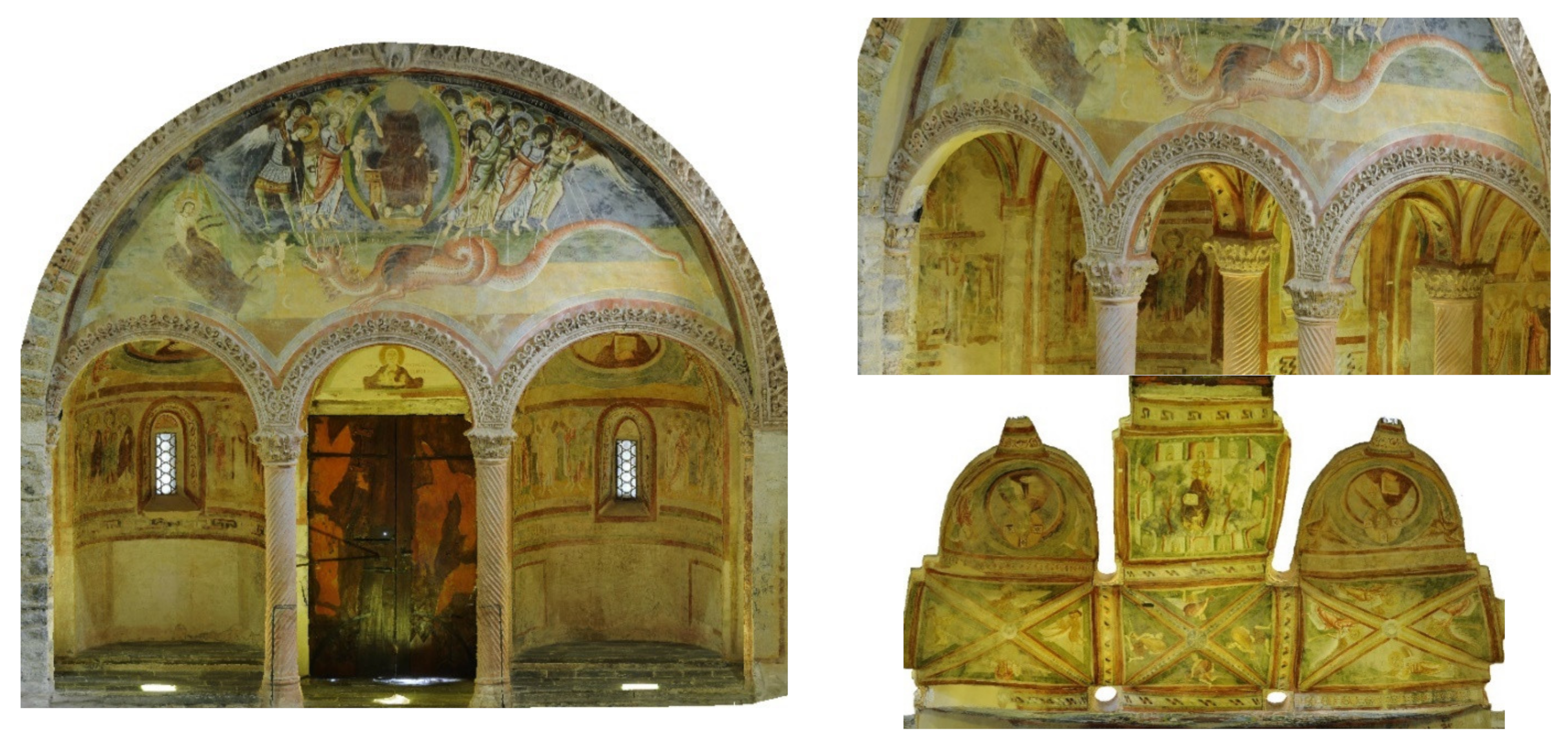
In the case of the digital recording project at the Basilica, fisheye photogrammetry was used to reconstruct the entrance of the complex. The space between façade and nave hosts a kind of narthex with a corridor and two small apses, featuring rich decorations such as frescoes and stuccos. A set of 84 images was sufficient to capture the entire space in about 15 min, which were processed in ContextCapture to generate a textured 3D model. Data processing was carried out importing and fixing calibration parameters. A set of control points in cartographic coordinates was used to georeference the final model, which can be imported into InfraWorks. Figure 10 shows some images of the final model.
5. Considerations and Outlooks
5.1. An Interoperable Platform for Multiple Specialists
Although metric data are fundamental for projects related to heritage conservation and restoration, the “I” of information in both BIM and GIS must is not limited to the datasets shown in the previous sections. Different specialists (architects, archeologists, conservators, engineers, historians, restorers, geologists, etc.) involved in conservation projects could require access, retrieval, or publication of various digital data in different formats, including information that could not be directly georeferenced.
The H-BIM-GIS could be exploited as a common platform for different purposes and multiple specialists. Other available sources can be directly incorporated into the system or can be linked to it using strategies such as points of interest, which can be generated in InfraWorks or ArcGIS Pro. In the case of creation in GIS, the point of interest (POI) is a point shapefile with associated information in the attribute table that can be transferred to InfraWorks, adding the specific parametrization as POI.
An example was the integration of a virtual tour of the complex, which was independently created with 3DVista and a set of 360° images taken with a Xiaomi Mi Sphere Camera. The virtual tool is available as an executable file that can be linked to the system and run as an independent application. Alternatively, specific POI could be generated in the georeferenced environment using icons. The user can activate this layer and a link to a shared version of the panoramic image is available using an online storage service, proving an immersive view in a web browser (Figure 11).
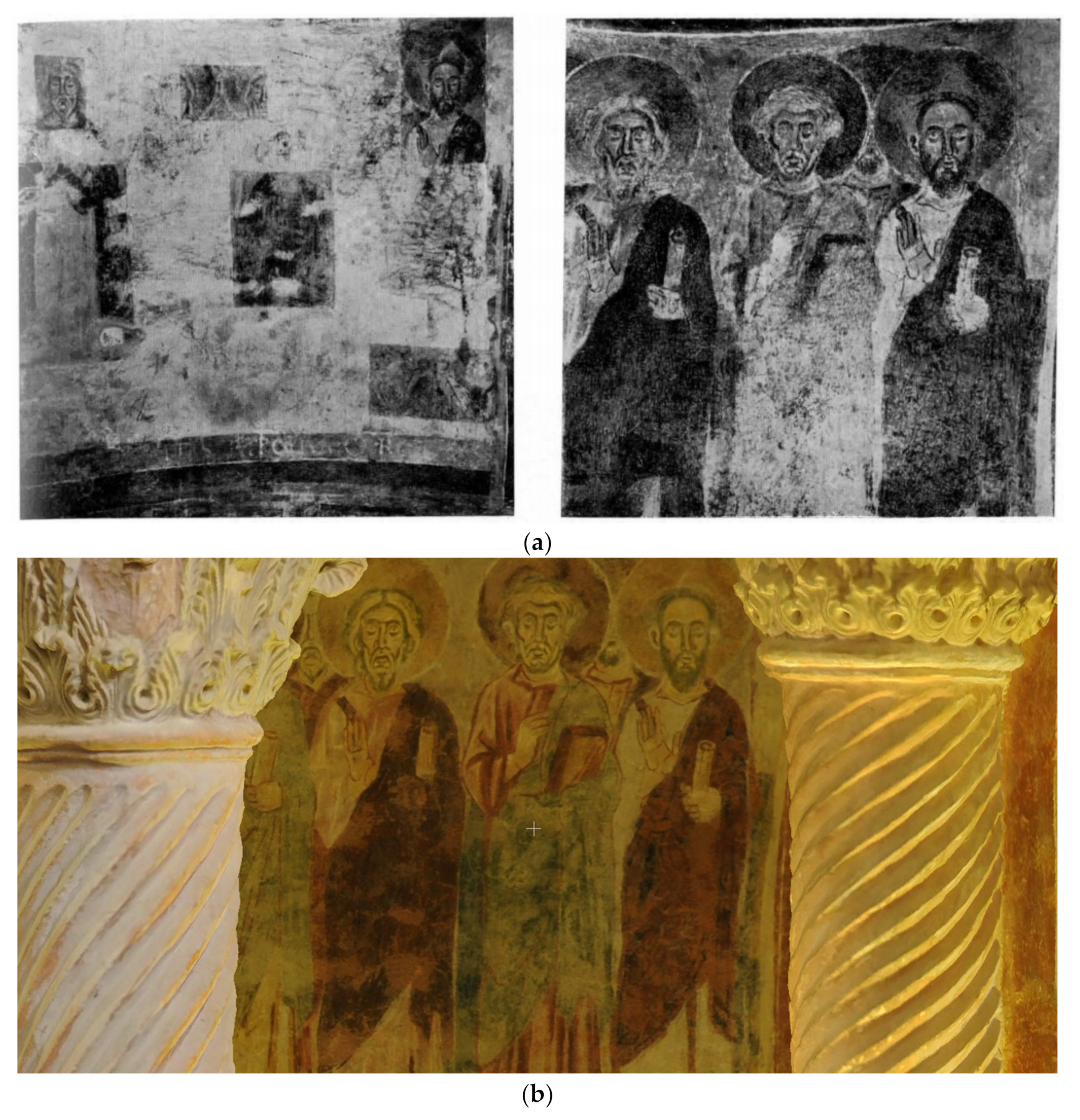
Another example is the connection to the model of historic photographs during restoration works. Also, specific POIs can be added to the model to inform the user about the availability of such images. In the case of Figure 12 (top), pictures on top show the restoration carried out inside a small apse, after and before the intervention [41]. The image on the bottom is the 3D textured model from fisheye photogrammetry showing actual conditions. The model could also be used to generate orthophotos. In this case, the surface could be approximated with a cylinder, and the textured mesh can be unrolled to create orthophotos that do not deform areas.
5.2. Working with Multiple Project Proposals
Project proposals allow a different way to store multiple versions of the model in the same environment. The work described in the previous section introduced a possible subdivision of the data into “proposal 1” (the preliminary solution generated with Model Builder), and “proposal 2” (the refined model based on a local repository of geospatial data). Additional proposals were generated to include a variety of information from the in situ survey (3D models from photogrammetry and laser scanning), virtual reality, pictures from previous restorations, documentation from textbooks and papers, etc.
The system can automatically switch from the different proposals without changing the point of view of the observer. This is useful to generate a visualization of the changes that occurred between the different projects. It can also be used to show changes between different versions of the monument, e.g., after and before restoration interventions.
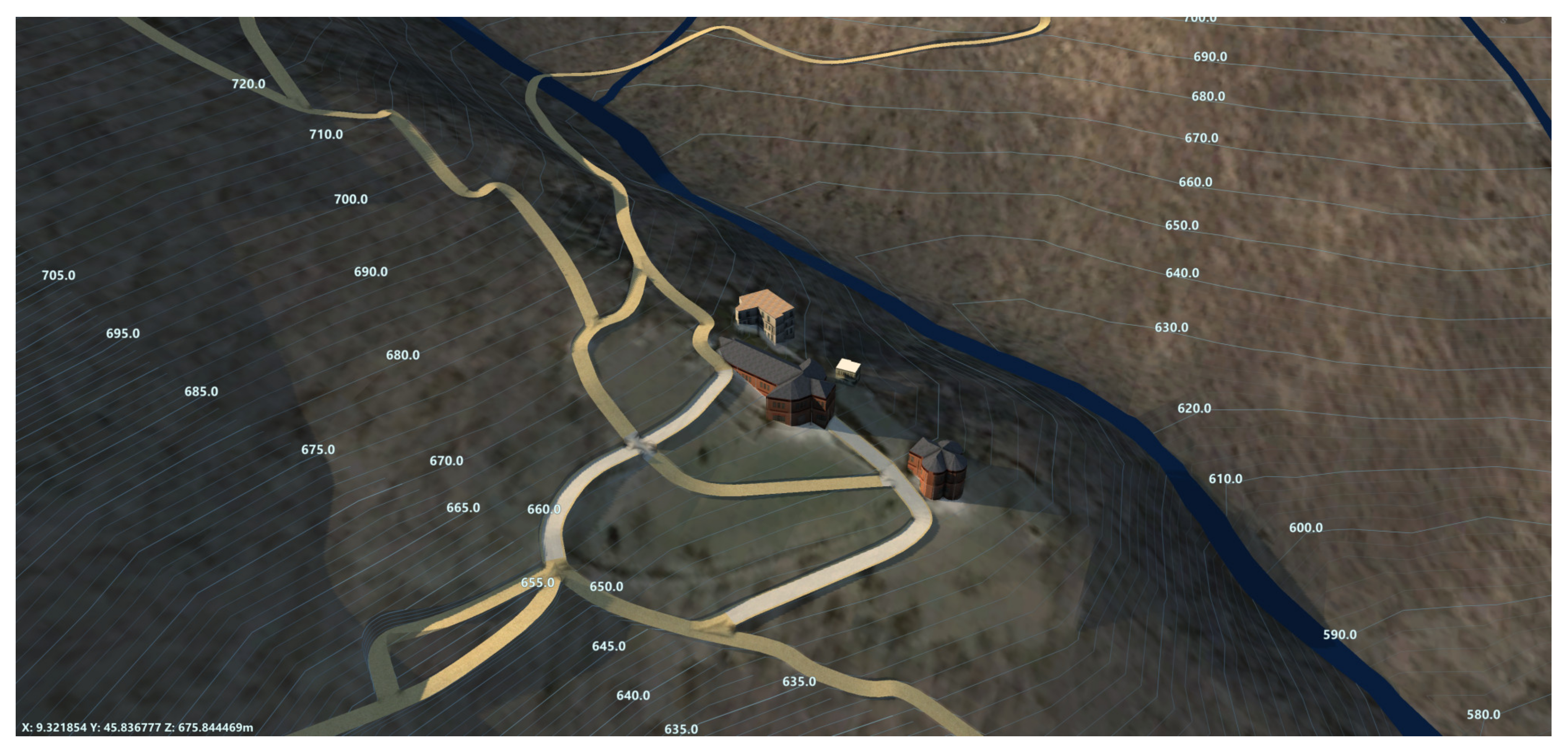
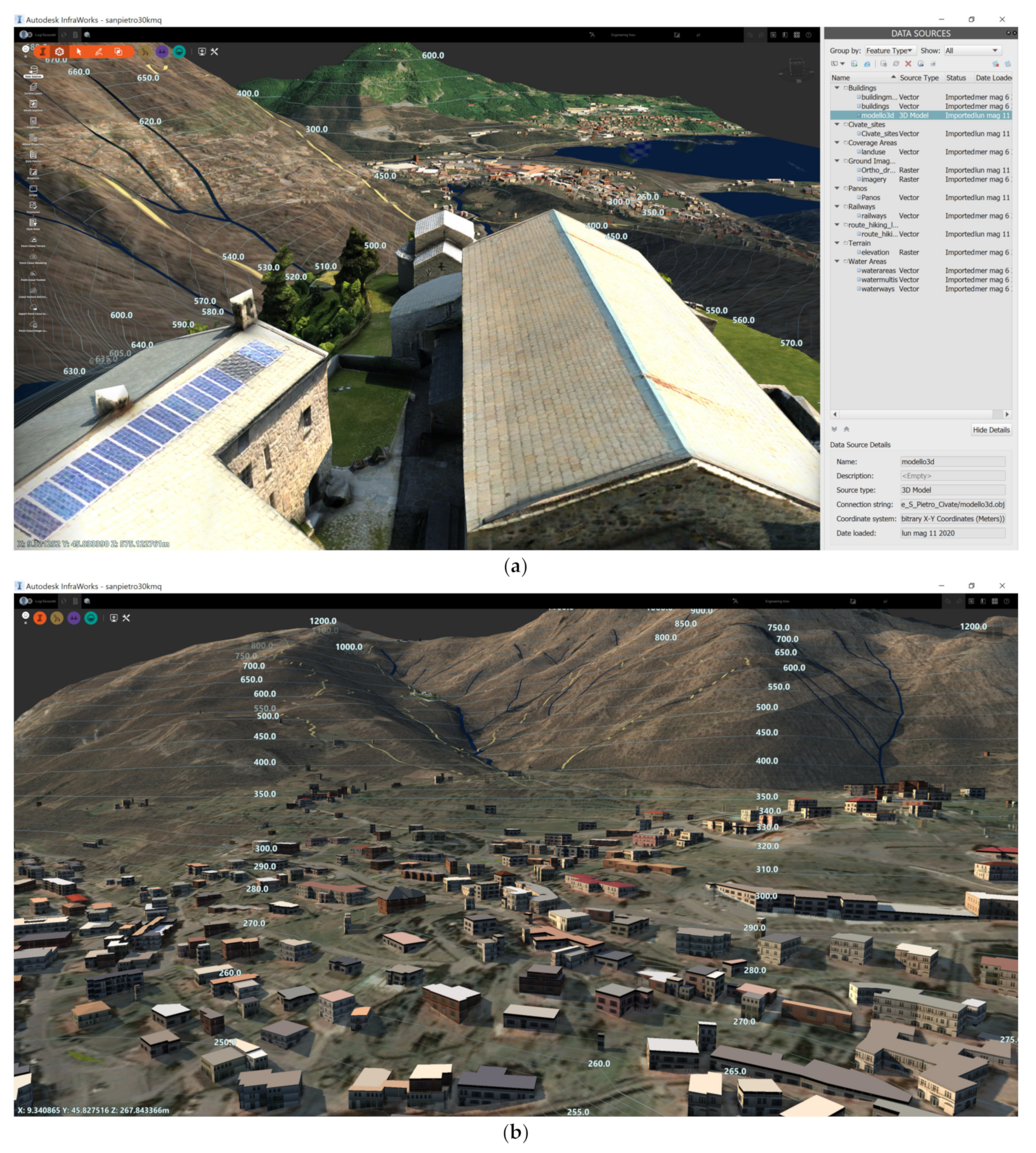
Data can also be transferred (copied and moved) between different proposals. Figure 13 shows the model based on Model Builder with the 3D model of the complex generated with digital photogrammetry.
The 3D model of the complex has a much higher level of detail than other buildings in the project, which are still represented with simple boxes created using an extrusion of the base. The availability of a project organized into proposals allows users to include more details into a novel solution layer without losing the simplified geometry of the complex that could be still useful for geospatial operations. At the same time, if new 3D models become available, they can be inserted into the project without overwriting information at lower-level details.
6. Conclusions
This paper illustrated and discussed the creation of an H-BIM-GIS, which is intended as a 3D environment able to handle cartographic data along with other information acquired at the level of the building. The method extends traditional GIS or BIM approaches using a multi-scale approach, in which spatial consistency is provided using georeferencing techniques.
Different datasets were integrated into the platform. Digital maps typical of the GIS system can be directly imported using the available georeferencing information. Metric data acquired in-situ (laser scans, 3D models, etc.) generated with different methods can also be directly imported if georeferenced. The use of a GNSS receiver allows the measurement of specific points in a cartographic reference system so that the different local products can be georeferenced using such points. Finally, some examples of integration of information without georeferencing information (such as documents, reports, historic photographs, etc.) were shown in order to demonstrate how such data can be connected to the model using POIs.
The approach relies on two software packages (InfraWorks, ArcGIS Pro) that are simultaneously exploited to cope with reciprocal pros and cons. The software can share data using traditional import/export tools as well as more direct data exchange using online services (ArcGIS Online, Connector for ArcGIS). It is the authors’ opinion that the use of this interconnected software provides several tools and more opportunities for advanced analysis, notwithstanding that more software requires more resources and technical skills.
The organization of the project based on proposals is also a novel solution compared to traditional approaches in which a single version of the model can be stored in the file. Multiple proposals were here used to keep the preliminary and enhanced versions of the model. Data can also be transferred from the different proposals, resulting in a useful solution when the model must serve the purposes of different specialists who could require different typologies of data.
Future work is required to improve interoperability between the software. If data can be transferred from different environments (without generating redundant copies), tools and functions available in specific software (such as geospatial analysis tools in GIS) can be exploited without the need of reimplementing them in different packages. Additional issues also concern the rigid structure of the software, which tend to be mainly oriented to more modern constructions (including infrastructure in the case of InfraWorks). Indeed, historic buildings and sites often feature peculiar characteristics that cannot be handled by parametric modeling tools developed for regular elements.
Author Contributions
Conceptualization, L.B. and F.R.; methodology, L.B. and F.R.; software, L.B.; validation, L.B., F.R. writing, L.B.; writing—review and editing, L.B. All authors have read and agreed to the published version of the manuscript.
Funding
This research received no external funding.
Institutional Review Board Statement
Not applicable.
Informed Consent Statement
Not applicable.
Data Availability Statement
Not Applicable.
Acknowledgments
The authors want to acknowledge the Associazione Amici di San Pietro al Monte, which provided access to the site and support during the different years in which the work has been conducted. We would like also to thank some colleagues and students that participated in some acquisition campaigns: Valente R., Sala M., E. Ambrosini, Zhivkovikj B., Canali D., Mainetti F., Rizzi E.
Conflicts of Interest
The authors declare no conflict of interest.
References
- Murphy, M.; McGovern, E.; Pavia, S. Historic Building Information Modelling (HBIM). Struct. Surv. 2009, 27, 311–327. [Google Scholar] [CrossRef] [Green Version]
- Murphy, M.; McGovern, E.; Pavia, S. Historic Building Information Modelling—Adding Intelligence to Laser and Image Based Surveys of European Classical Architecture. ISPRS J. Photogramm. Remote Sens. 2013, 76, 89–102. [Google Scholar] [CrossRef]
- Murphy, M.; McGovern, E.; Pavia, S. Parametric Vector Modelling of Laser and Image Surveys of 17th Century Classical Architecture in Dublin. In Proceedings of the 8th International Symposium on Virtual Reality, Archaeology and Cultural Heritage VAST, Brighton, UK, 26–30 November 2007. [Google Scholar]
- Chiabrando, F.; Sammartano, G.; Spanò, A. Historical Buildings Models and Their Handling via 3d Survey: From Points Clouds to User-Oriented Hbim. In Proceedings of the XXIII ISPRS Congress, Prague, Czech Republic, 12–19 July 2016; Volume 41B5, pp. 633–640. [Google Scholar] [CrossRef] [Green Version]
- Pocobelli, D.; Boehm, J.; Bryan, P.; Still, J.; Grau-Bové, J. BIM for Heritage Science: A Review. Herit. Sci. 2018, 6, 30. [Google Scholar] [CrossRef] [Green Version]
- Fassi, F.; Fregonese, L.; Adami, A.; Rechichi, F. BIM System for the Conservation and Preservation of the Mosaics of San Marco in Venice. In Proceedings of the International Archives of the Photogrammetry, Remote Sensing and Spatial Information Sciences, Ottawa, ON, Canada, 18 August 2017; Volume XLII-2-W5, pp. 229–236. [Google Scholar]
- Pybus, C.; Graham, K.; Doherty, J.; Arellano, N.; Fai, S. New Realities for Canada’s Parliament: A Workflow for Preparing Heritage Bim for Game Engines and Virtual Reality. In Proceedings of the 27th CIPA International Symposium “Documenting the Past for a Better Future”, Ávila, Spain, 1–5 September 2019; Volume XLII-2-W15, pp. 945–952. [Google Scholar]
- Oreni, D.; Brumana, R.; Torre, S.D.; Banfi, F.; Previtali, M. Survey Turned into HBIM: The Restoration and the Work Involved Concerning the Basilica Di Collemaggio after the Earthquake (L’Aquila). In Proceedings of the ISPRS Technical Commission V Symposium, Riva del Garda, Italy, 23–25 June 2014; Volume II, pp. 267–273. [Google Scholar] [CrossRef] [Green Version]
- Reina Ortiz, M.; Yang, C.; Weigert, A.; Dhanda, A.; Min, A.; Gyi, M.; Su, S.; Fai, S.; Santana Quintero, M. Integrating heterogeneous datasets in HBIM of decorated surfaces. In Proceedings of the 27th CIPA International Symposium “Documenting the Past for a Better Future”, Ávila, Spain, 1–5 September 2019; Volume 42, pp. 981–988. [Google Scholar]
- Prizeman, O.E.C. HBIM and Matching Techniques: Considerations for Late Nineteenth- and Early Twentieth-Century Buildings. J. Archit. Conserv. 2015, 21, 145–159. [Google Scholar] [CrossRef]
- Alshawabkeh, Y.; Baik, A.; Miky, Y. Integration of Laser Scanner and Photogrammetry for Heritage BIM Enhancement. ISPRS Int. J. Geo-Inf. 2021, 10, 316. [Google Scholar] [CrossRef]
- Remondino, F. Heritage Recording and 3D Modeling with Photogrammetry and 3D Scanning. Remote Sens. 2011, 3, 1104–1138. [Google Scholar] [CrossRef] [Green Version]
- Yang, X.; Grussenmeyer, P.; Koehl, M.; Macher, H.; Murtiyoso, A.; Landes, T. Review of Built Heritage Modelling: Integration of HBIM and Other Information Techniques. J. Cult. Herit. 2020, 46, 350–360. [Google Scholar] [CrossRef]
- Barazzetti, L.; Banfi, F.; Brumana, R.; Previtali, M. Creation of Parametric BIM Objects from Point Clouds Using Nurbs. Photogramm. Rec. 2015, 30, 339–362. [Google Scholar] [CrossRef]
- Barazzetti, L. Parametric As-Built Model Generation of Complex Shapes from Point Clouds. Adv. Eng. Inform. 2016, 30, 298–311. [Google Scholar] [CrossRef]
- Dore, C.; Murphy, M. Semi-Automatic Modelling Of Building Façades With Shape Grammars Using Historic Building Information Modelling. In Proceedings of the 3D-ARCH 2013—3D Virtual Reconstruction and Visualization of Complex Architectures, Trento, Italy, 25–26 February 2013; Volume XL-5/W1, pp. 57–64. [Google Scholar] [CrossRef]
- Ruoss, E.; Alfare, L.; Vallone, R.; Moscatelli, M.; Zumaglini, M.; Grünner, R.; Klementschitz, R.; Richard, L. GIS as Tool for Cultural Heritage Management. In Sustainable Tourism as Driving Force Forcultural Heritage Sites Development; CNR IGAG: Rome, Italy, 2013; pp. 42–46. [Google Scholar]
- Sharafat, A.; Khan, M.S.; Latif, K.; Tanoli, W.A.; Park, W.; Seo, J. Bim-Gis-Based Integrated Framework for Underground Utility Management System for Earthwork Operations. Appl. Sci. 2021, 11, 5721. [Google Scholar] [CrossRef]
- Garramone, M.; Moretti, N.; Scaioni, M.; Ellul, C.; Re Cecconi, F.; Dejaco, M.C. BIM and GIS Integration for infrastructure asset management: A bibliometric analysis. In Proceedings of the 15th 3D GeoInfo Conference, London, UK, 7–11 September 2020; Volume 6, pp. 77–84. [Google Scholar]
- Barazzetti, L.; Banfi, F. BIM and GIS: When parametric modeling meets geospatial data. In Proceedings of the ISPRS Annals of the Photogrammetry, Remote Sensing and Spatial Information Sciences, Kyiv, Ukraine, 4–6 December 2017; Copernicus GmbH: Kyiv, Ukraine, 2017; Volume IV-5-W1, pp. 1–8. [Google Scholar]
- Barazzetti, L.; Previtali, M.; Roncoroni, F. Can we use low-cost 360 degree cameras to create accurate 3D models? Int. Arch. Photogramm. Remote Sens. Spatial Inf. Sci. 2018, 42, 69–75. [Google Scholar] [CrossRef] [Green Version]
- Chiappini, S.; Fini, A.; Malinverni, E.S.; Frontoni, E.; Racioppi, G.; Pierdicca, R. Cost effective spherical photogrammetry: A novel framework for the smart management of complex urban environments. In Proceedings of the International Archives of the Photogrammetry, Remote Sensing and Spatial Information Sciences, Nice, France, 31 August–2 September 2020; Copernicus GmbH: Nice, France, 2020; Volume XLIII-B4-2020, pp. 441–448. [Google Scholar]
- Perfetti, L.; Fassi, F.; Rossi, C. Fisheye photogrammetry to generate low-cost DTMs. In Proceedings of the International Archives of the Photogrammetry, Remote Sensing and Spatial Information Sciences, Strasbourg, France, 2–3 December 2019; Copernicus GmbH: Strasbourg, France, 2019; Volume XLII-2-W17, pp. 257–263. [Google Scholar]
- Strecha, C.; Zoller, R.; Rutishauser, S.; Brot, B.; Schneider-Zapp, K.; Chovancova, V.; Krull, M.; Glassey, L. Quality assessment of 3D reconstruction using fisheye and perspective sensors. In Proceedings of the PIA15+HRIGI15—Joint ISPRS Conference 2015, Munich, Germany, 25–27 March 2015; Voume II-3-W4, pp. 215–222. [Google Scholar]
- Coordinate Systems Worldwide (EPSG/ESRI). Available online: https://epsg.io/ (accessed on 31 July 2021).
- Wade, T.; Wickham, J.; Nash, M.; Neale, A.; Riitters, K.; Jones, K. A Comparison of Vector and Raster GIS Methods for Calculating Landscape Metrics Used in Environmental Assessments. Photogramm. Eng. Remote Sens. 2003, 69, 1399–1405. [Google Scholar] [CrossRef] [Green Version]
- Agapiou, A.; Lysandrou, V.; Alexakis, D.D.; Themistocleous, K.; Cuca, B.; Argyriou, A.; Sarris, A.; Hadjimitsis, D.G. Cultural Heritage Management and Monitoring Using Remote Sensing Data and GIS: The Case Study of Paphos Area, Cyprus. Comput. Environ. Urban Syst. 2015, 54, 230–239. [Google Scholar] [CrossRef]
- Bašić, T.; Varga, M. A Brief (Historical) Review on Definitions and Applications of the Geoid. In Proceedings of the X Hotine-Marussi Symposium, Rome, Italy, 18–22 June 2018. [Google Scholar]
- Barzaghi, R.; Borghi, A.; Carrion, D.; Sona, G. Refining the Estimate of the Italian Quasi-Geoid. Boll. Geod. Sci. Affin. 2007, 46, 145–160. [Google Scholar]
- Roura, P.; Calbó, J. Measurement of the Earth’s Radius Based on Historical Evidence of Its Curvature. Phys. Educ. 2005, 40, 455. [Google Scholar] [CrossRef]
- Karimi, S.; Iordanova, I. Integration of BIM and GIS for Construction Automation, a Systematic Literature Review (SLR) Combining Bibliometric and Qualitative Analysis. Arch. Computat. Methods Eng. 2021, 53, 41–52. [Google Scholar] [CrossRef]
- Saghravani, S.R.; Mustapha, S.; Saghravani, S.F.; Ibrahim, S.; Yusoff, M. Performance of Real-Time Kinematic Global Positioning System and Automatic Level Surveying for Height Determination—A Comparison. In Proceedings of the 2009 International Conference on Signal Acquisition and Processing, Kuala Lumpur, Malaysia, 3–5 April 2009; p. 111. [Google Scholar]
- GNSS Positioning Service Portal of Regione Piemonte, Regione Lombardia and Regione Valle d’Aosta. Available online: https://www.spingnss.it/spiderweb/frmIndex.aspx (accessed on 30 July 2021).
- Hofmann-Wellenhof, B.; Lichtenegger, H.; Wasle, E. GNSS—Global Navigation Satellite Systems: GPS, GLONASS, Galileo, and more; Springer: Vienna, Austria, 2008; pp. 193–276. [Google Scholar]
- Fangi, G.; Pierdicca, R.; Sturari, M.; Malinverni, E.S. Improving spherical photogrammetry using 360° omni-cameras: Use cases and new applications. In Proceedings of the ISPRS TC II Mid-Term Symposium “Towards Photogrammetry 2020”, Riva del Garda, Italy, 4–7 June 2018; Volume XLII-2, pp. 331–337. [Google Scholar] [CrossRef] [Green Version]
- Barazzetti, L.; Previtali, M.; Roncoroni, F. 3D modelling with the Samsung Gear 360. In Proceedings of the International Archives of the Photogrammetry, Remote Sensing and Spatial Information Sciences, Nafplio, Greece, 1–3 March 2017; Copernicus GmbH: Nafplio, Greece, 2017; Volume XLII-2-W3, pp. 85–90. [Google Scholar]
- Kwiatek, K.; Tokarczyk, R. Photogrammetric Applications of Immersive Video Cameras. In Proceedings of the ISPRS Technical Commission V Symposium, Riva del Garda, Italy, 23–25 June 2014; Volume II-5, pp. 211–218. [Google Scholar] [CrossRef] [Green Version]
- Barazzetti, L.; Previtali, M.; Roncoroni, F.; Valente, R. Connecting inside and outside through 360° imagery for close-range photogrammetry. In Proceedings of the 8th International Workshop 3D-ARCH “3D Virtual Reconstruction and Visualization of Complex Architectures”, Bergamo, Italy, 6–8 February 2019; Volume XLII-2-W9, pp. 87–92. [Google Scholar]
- Perfetti, L.; Polari, C.; Fassi, F. Fisheye photogrammetry: Tests and methodologies for the survey of narrow spaces. In Proceedings of the International Archives of the Photogrammetry, Remote Sensing and Spatial Information Sciences, Nafplio, Greece, 1–3 March 2017; Copernicus GmbH: Nafplio, Greece, 2017; Volume XLII-2-W3, pp. 573–580. [Google Scholar]
- Barazzetti, L.; Previtali, M.; Roncoroni, F. Fisheye lenses for 3D modeling: Evaluations and considerations. In Proceedings of the ISPRS—International Archives of the Photogrammetry, Remote Sensing and Spatial Information Sciences 2017, Nafplio, Greece, 1–3 March 2017; Volume XLII-2/W3, pp. 79–84. [Google Scholar] [CrossRef] [Green Version]
- Perfetti, L.; Polari, C.; Fassi, F. Fisheye multi-camera system calibration for surveying narrow and complex architectures. In Proceedings of the International Archives of the Photogrammetry, Remote Sensing and Spatial Information Sciences, Riva del Garda, Italy, 4–7 June 2018; Copernicus GmbH: Riva del Garda, Italy, 2018; Volume XLII-2, pp. 877–883. [Google Scholar]
Figure 1.
The complex of San Pietro al Monte in Civate (Italy).
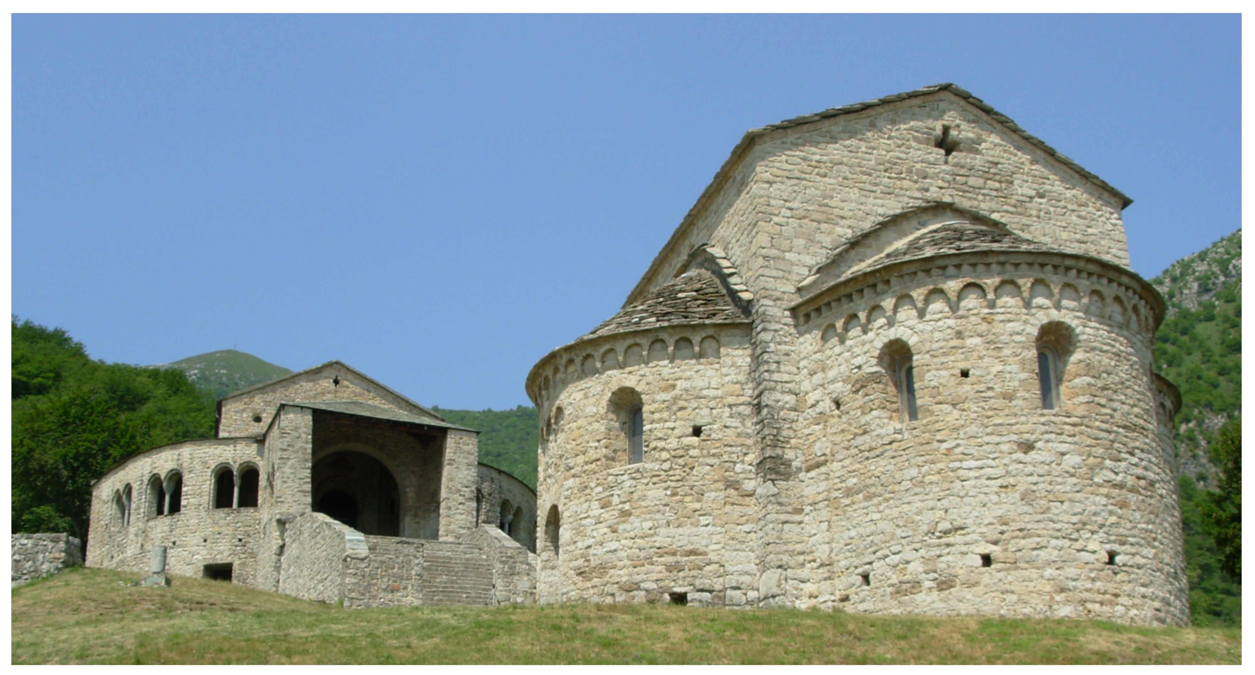
Figure 2.
3D visualization of the preliminary H-BIM-GIS including the municipality of Civate. The red circle indicates the location of the complex of San Pietro al Monte.
Figure 2.
3D visualization of the preliminary H-BIM-GIS including the municipality of Civate. The red circle indicates the location of the complex of San Pietro al Monte.

Figure 3.
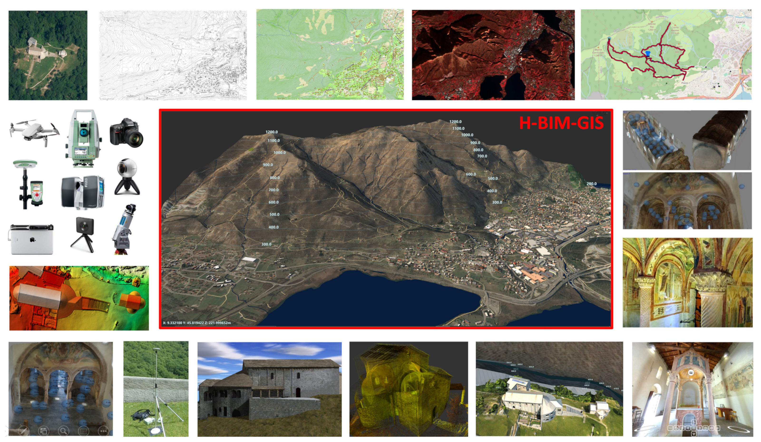
The H-BIM-GIS integrates multiple data using a multi-scale approach: from the cartographic level to the details of the building. The image shows some of the data that can be stored: (from top left corner—clockwise order) orthophoto from aerial photogrammetry, CTR (regional cartographic map), some GIS vector layers, false color Sentinel-2 image, mountain path shapefiles, textured meshes from spherical and fisheye photogrammetry, virtual reality (VR) tours (bottom right corner), mesh from drone images, laser scanning point cloud, 3D model from manual modeling, GNSS data, DEM, and some of the instruments used.
Figure 3.
The H-BIM-GIS integrates multiple data using a multi-scale approach: from the cartographic level to the details of the building. The image shows some of the data that can be stored: (from top left corner—clockwise order) orthophoto from aerial photogrammetry, CTR (regional cartographic map), some GIS vector layers, false color Sentinel-2 image, mountain path shapefiles, textured meshes from spherical and fisheye photogrammetry, virtual reality (VR) tours (bottom right corner), mesh from drone images, laser scanning point cloud, 3D model from manual modeling, GNSS data, DEM, and some of the instruments used.

Figure 4.
Data can be exchanged using traditional import/export tools or a more direct connection between the packages based on online services.
Figure 4.
Data can be exchanged using traditional import/export tools or a more direct connection between the packages based on online services.
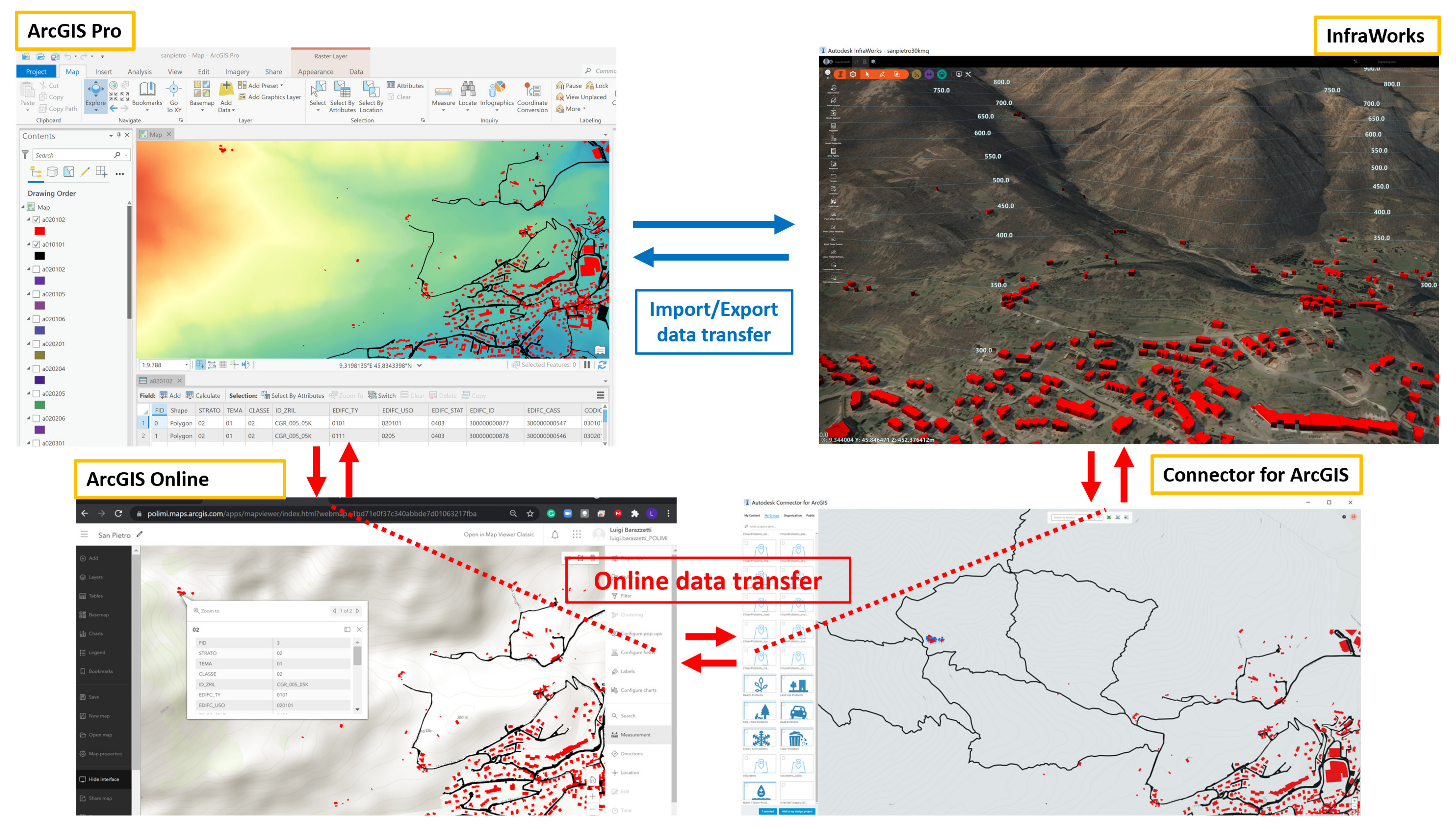
Figure 5.
The preliminary model of the building (proposal 1) and its limited level of detail at the scale of the monument.
Figure 5.
The preliminary model of the building (proposal 1) and its limited level of detail at the scale of the monument.

Figure 6.
Refinement of the initial model at a cartographic level (proposal p2) using GIS data (a) from regional repositories that can be added to InfraWorks (b).
Figure 6.
Refinement of the initial model at a cartographic level (proposal p2) using GIS data (a) from regional repositories that can be added to InfraWorks (b).
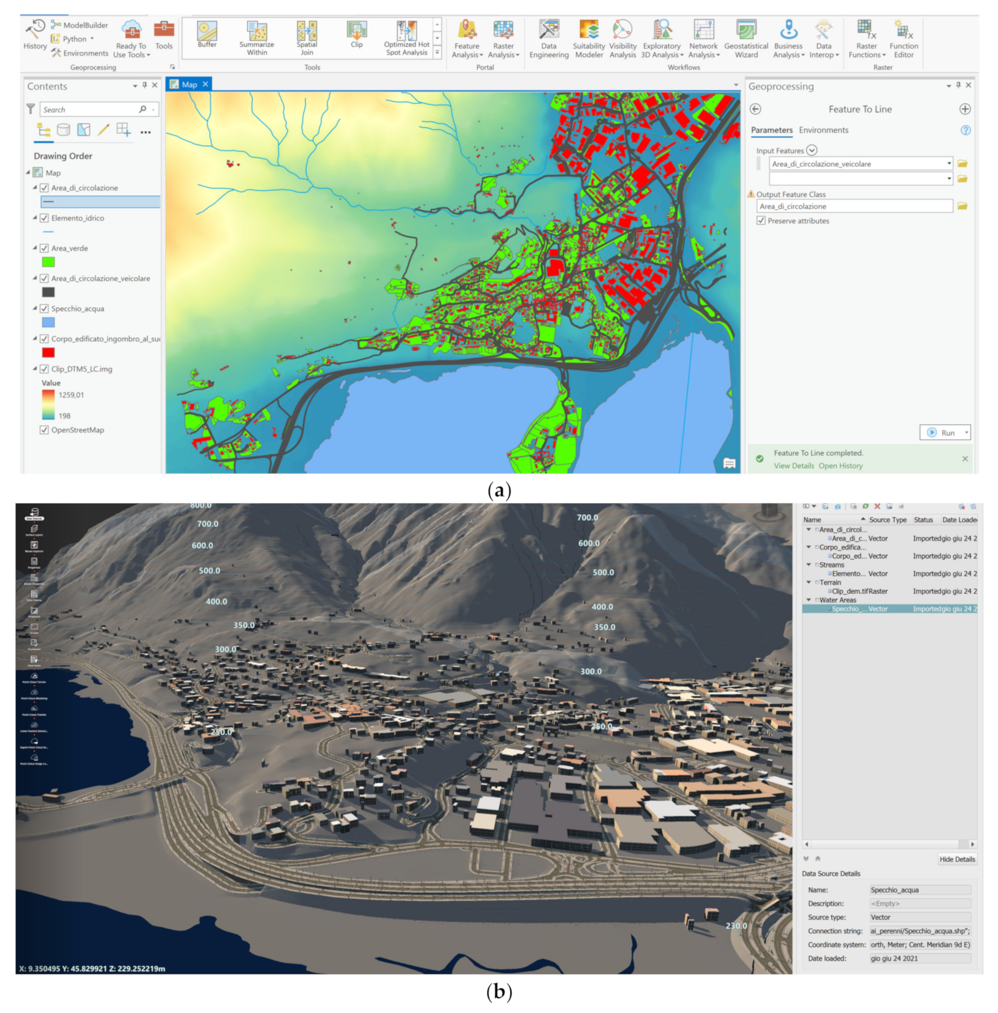
Figure 7.
3D model from drone integrated into the H-BIM-GIS (proposal 3).

Figure 8.
Digital elevation model (a) and high-resolution orthophoto (b) from drone images (proposal 3).
Figure 8.
Digital elevation model (a) and high-resolution orthophoto (b) from drone images (proposal 3).

Figure 9.
Images of the textured model generated with spherical photogrammetry: the interior of the church (images on top) and the crypt (images on bottom) (proposal 4).
Figure 9.
Images of the textured model generated with spherical photogrammetry: the interior of the church (images on top) and the crypt (images on bottom) (proposal 4).
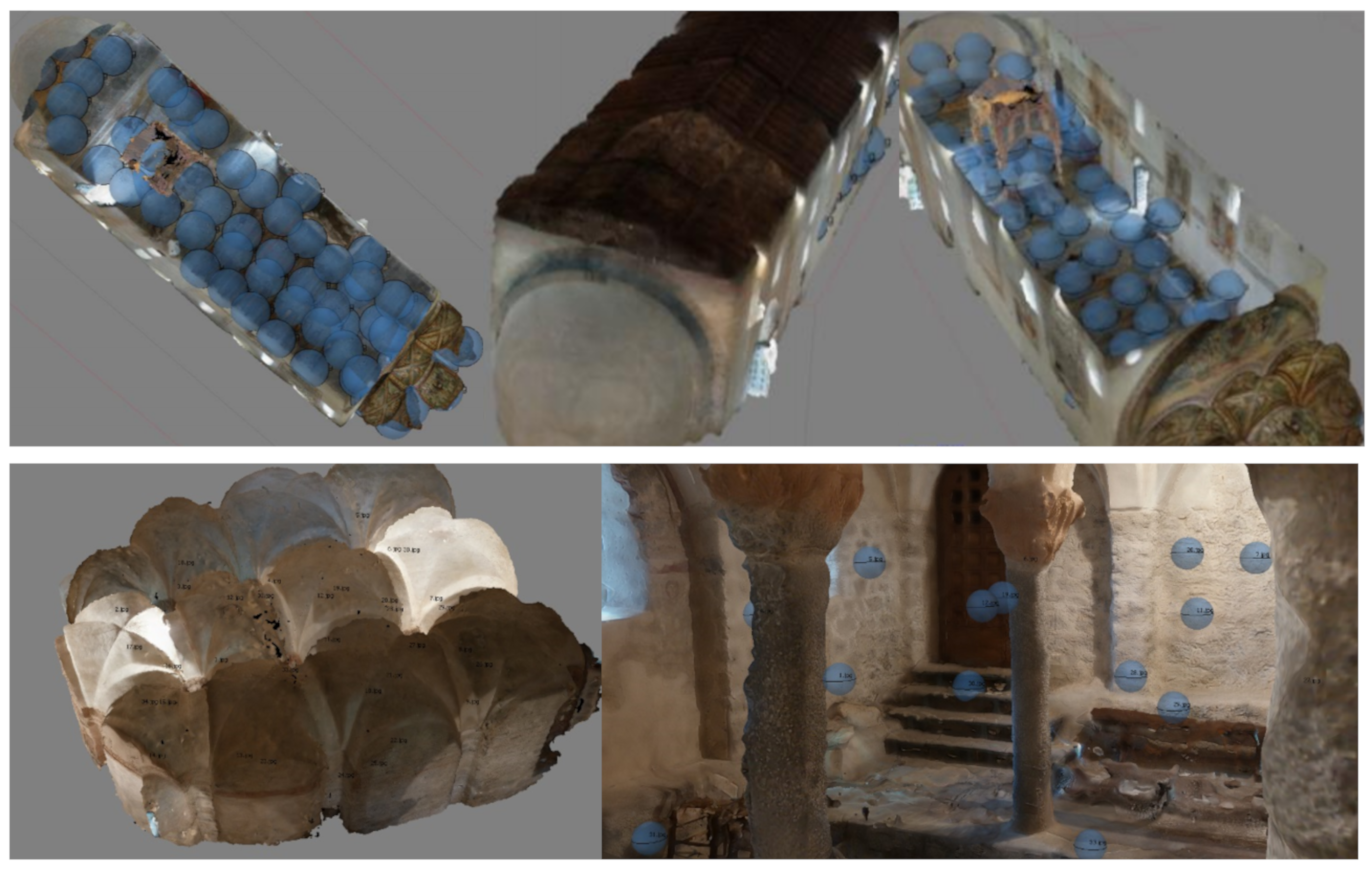
Figure 10.
Some images of the textured 3D model generated with fisheye photogrammetry (proposal 4).

Figure 11.
Some 360° images in the virtual tour are available as an executable file (exterior, church, and crypt) and the location of images in InfraWorks with a POI that allows the user to open the immersive visualization.
Figure 11.
Some 360° images in the virtual tour are available as an executable file (exterior, church, and crypt) and the location of images in InfraWorks with a POI that allows the user to open the immersive visualization.
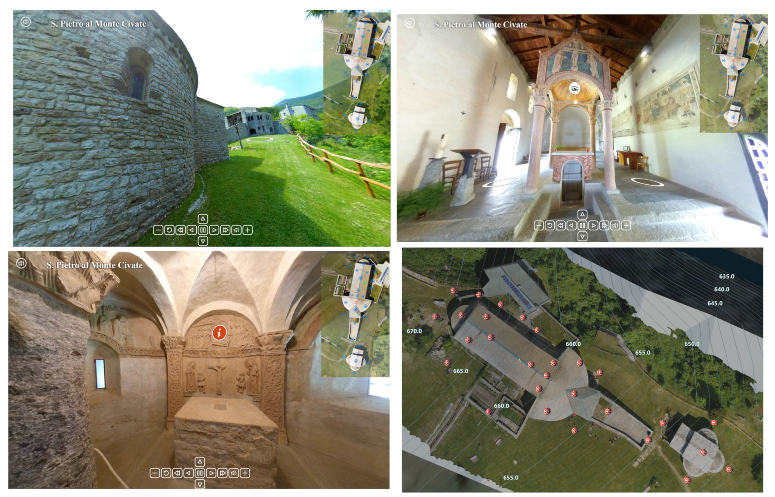
Figure 12.
Other information that was added consists of retrieval of information related to the previous restoration. The image shows the left apse before and after restoration (a). The textured 3D model showing actual conditions is shown on the bottom (b).
Figure 12.
Other information that was added consists of retrieval of information related to the previous restoration. The image shows the left apse before and after restoration (a). The textured 3D model showing actual conditions is shown on the bottom (b).

Figure 13.
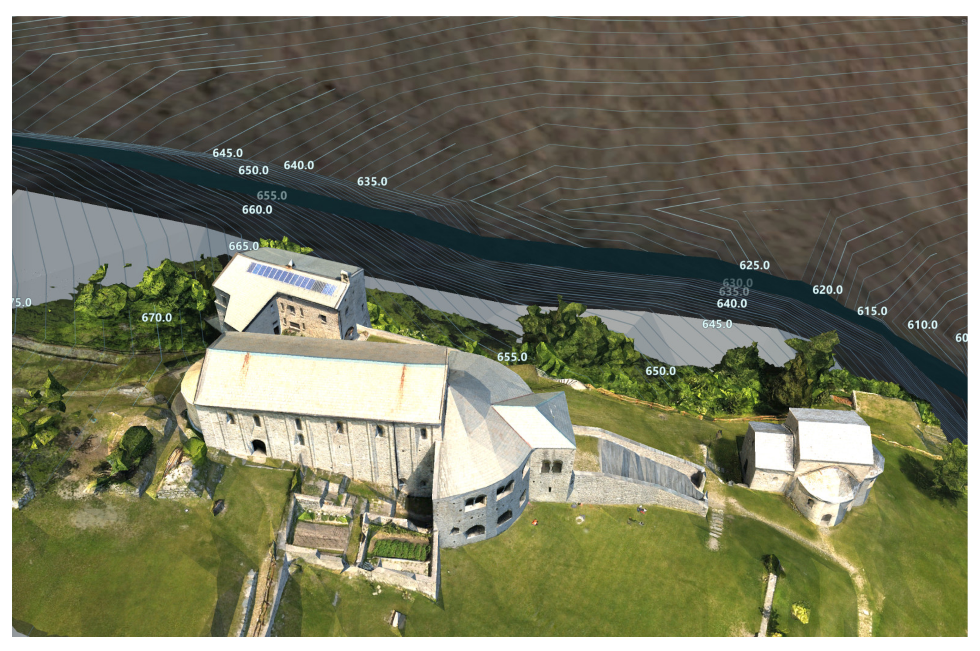
Some 3D visualizations of the model obtained mixing different proposals: (a) view from the basilica, and (b) view from the city at the bottom of the mountain.
Figure 13.
Some 3D visualizations of the model obtained mixing different proposals: (a) view from the basilica, and (b) view from the city at the bottom of the mountain.

Publisher’s Note: MDPI stays neutral with regard to jurisdictional claims in published maps and institutional affiliations. |
© 2021 by the authors. Licensee MDPI, Basel, Switzerland. This article is an open access article distributed under the terms and conditions of the Creative Commons Attribution (CC BY) license (https://creativecommons.org/licenses/by/4.0/).
Share and Cite
MDPI and ACS Style
Barazzetti, L.; Roncoroni, F. Generation of a Multi-Scale Historic BIM-GIS with Digital Recording Tools and Geospatial Information. Heritage 2021, 4, 3331-3348. https://doi.org/10.3390/heritage4040185
AMA Style
Barazzetti L, Roncoroni F. Generation of a Multi-Scale Historic BIM-GIS with Digital Recording Tools and Geospatial Information. Heritage. 2021; 4(4):3331-3348. https://doi.org/10.3390/heritage4040185
Chicago/Turabian StyleBarazzetti, Luigi, and Fabio Roncoroni. 2021. "Generation of a Multi-Scale Historic BIM-GIS with Digital Recording Tools and Geospatial Information" Heritage 4, no. 4: 3331-3348. https://doi.org/10.3390/heritage4040185