Architectural, Constructional and Structural Aspects of a Historic School in Greece. The Case of the Elementary School in Arnaia, Chalkidiki


Abstract
:1. Introduction
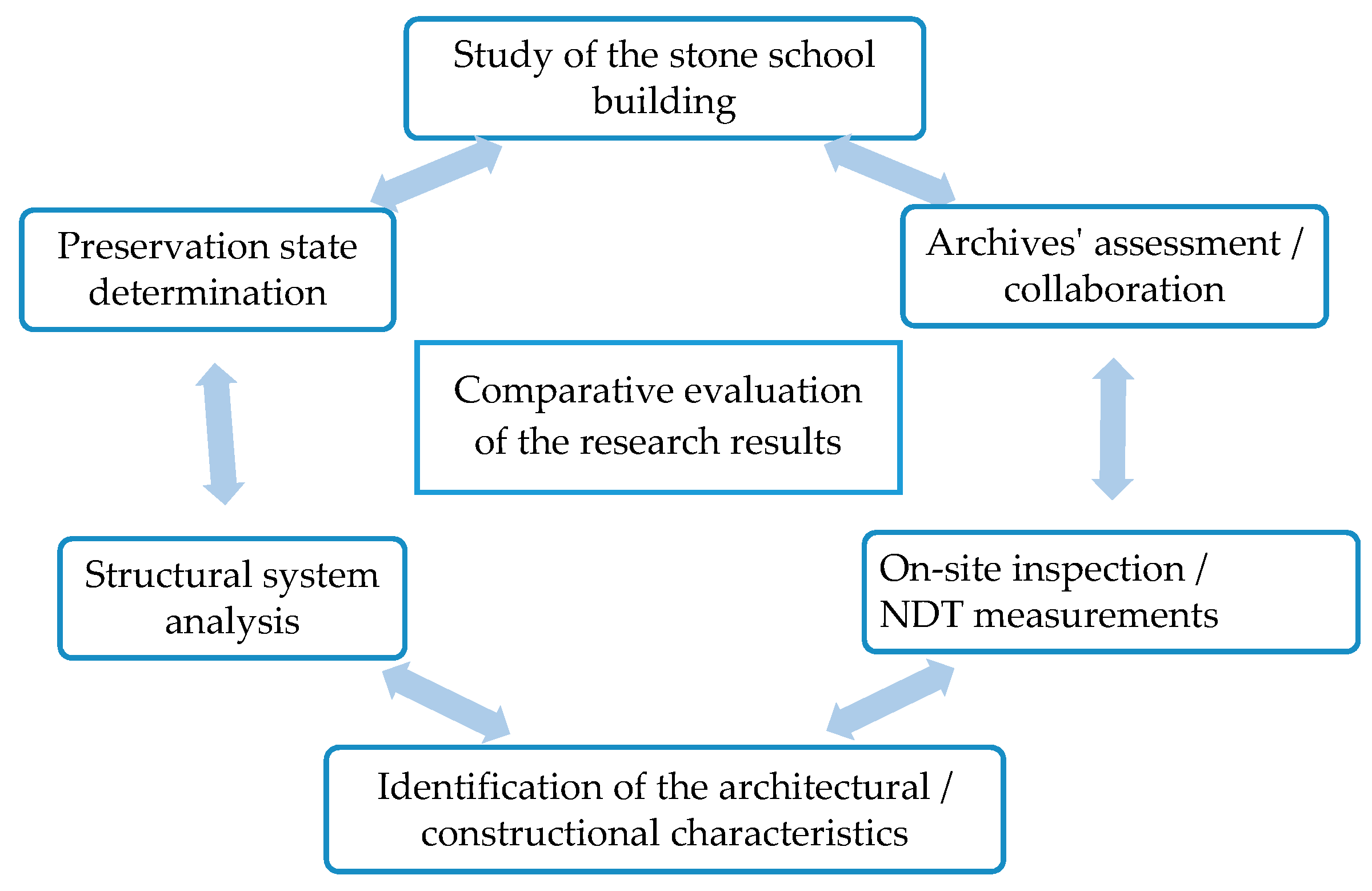
2. Methodology
3. Results and Discussion
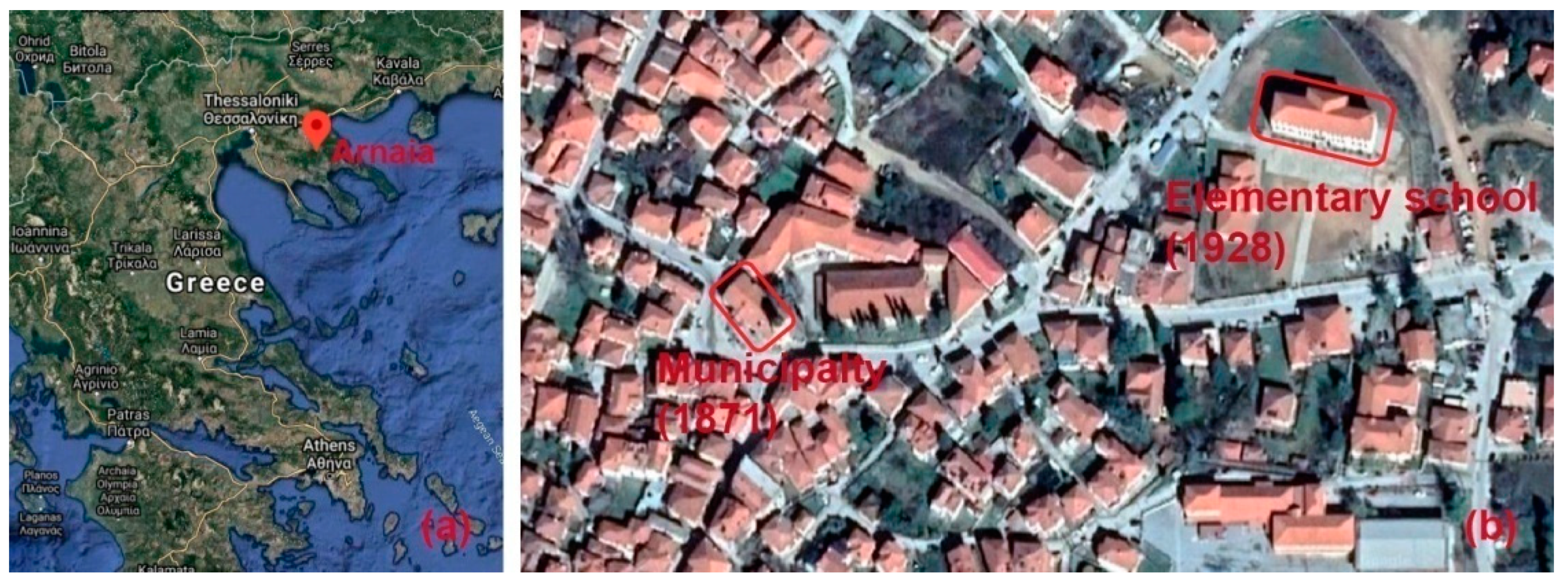
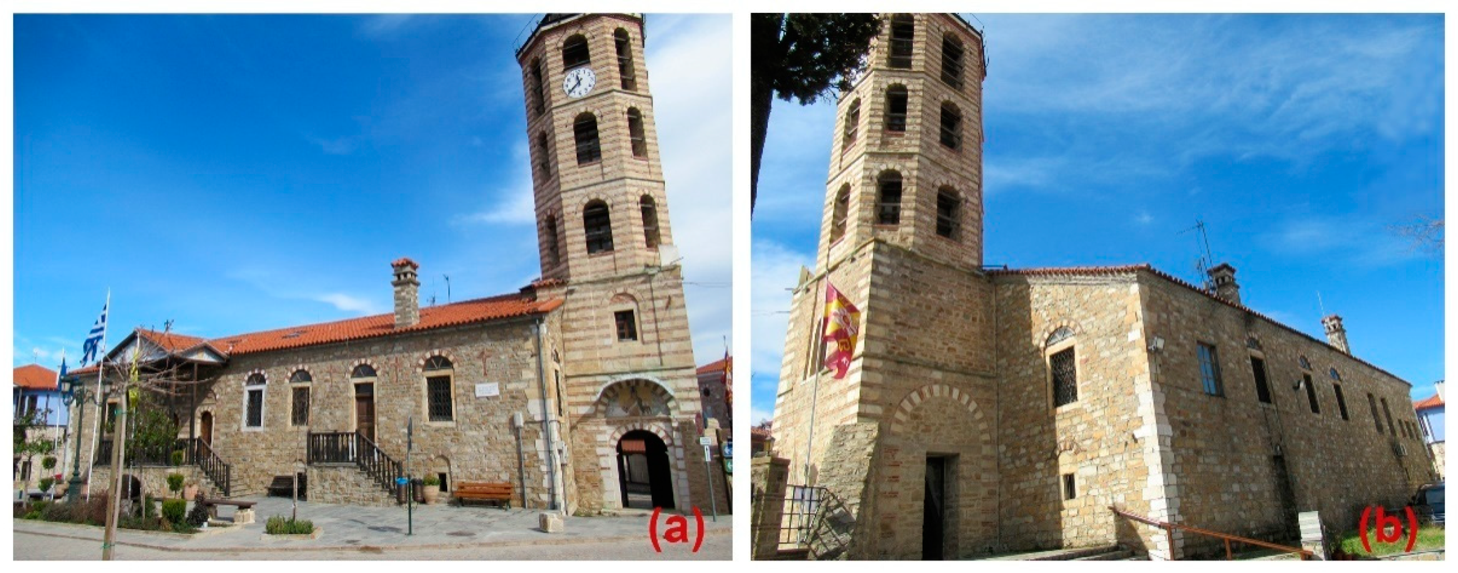
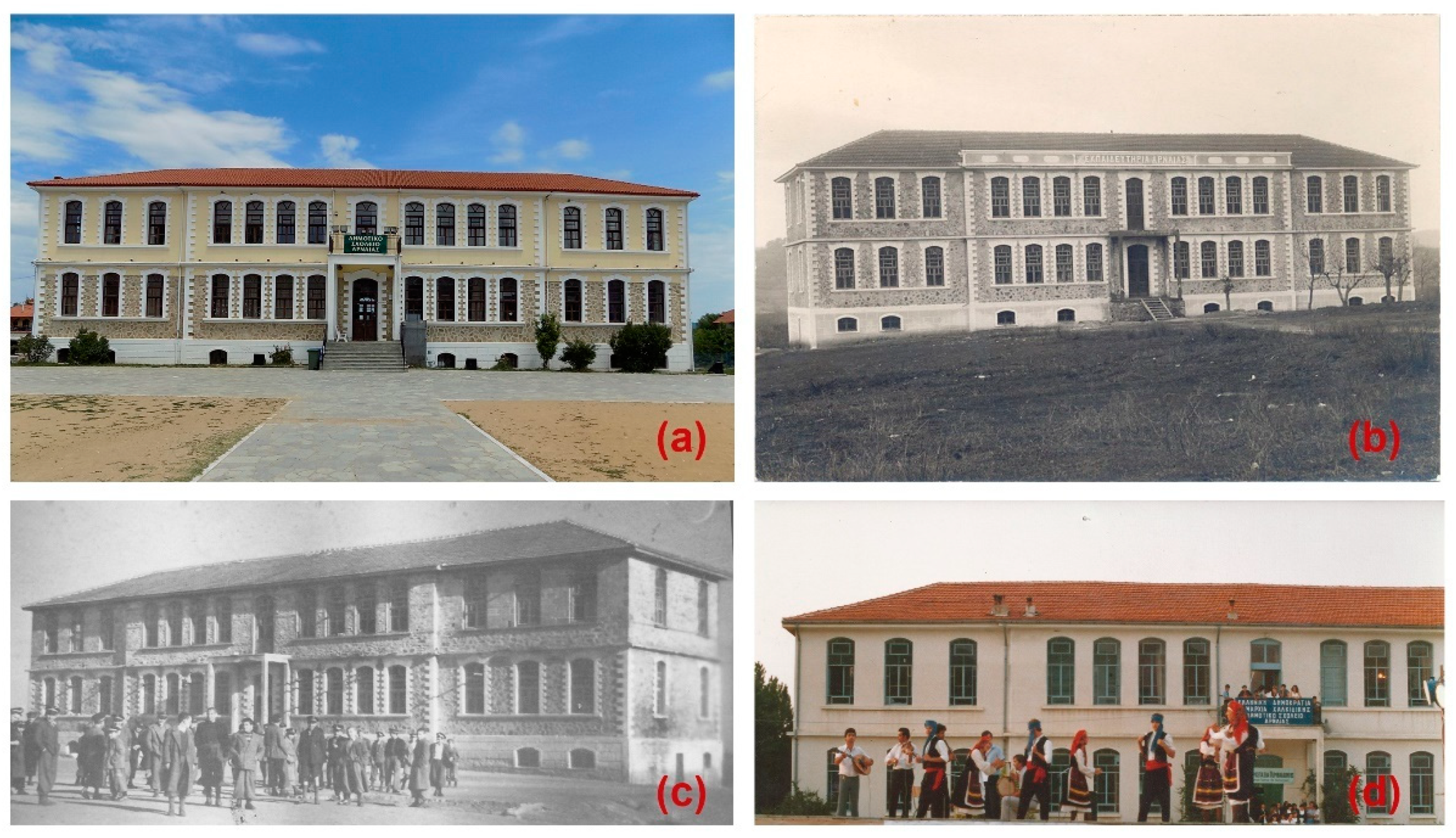
3.1. Geographical and Historical Background
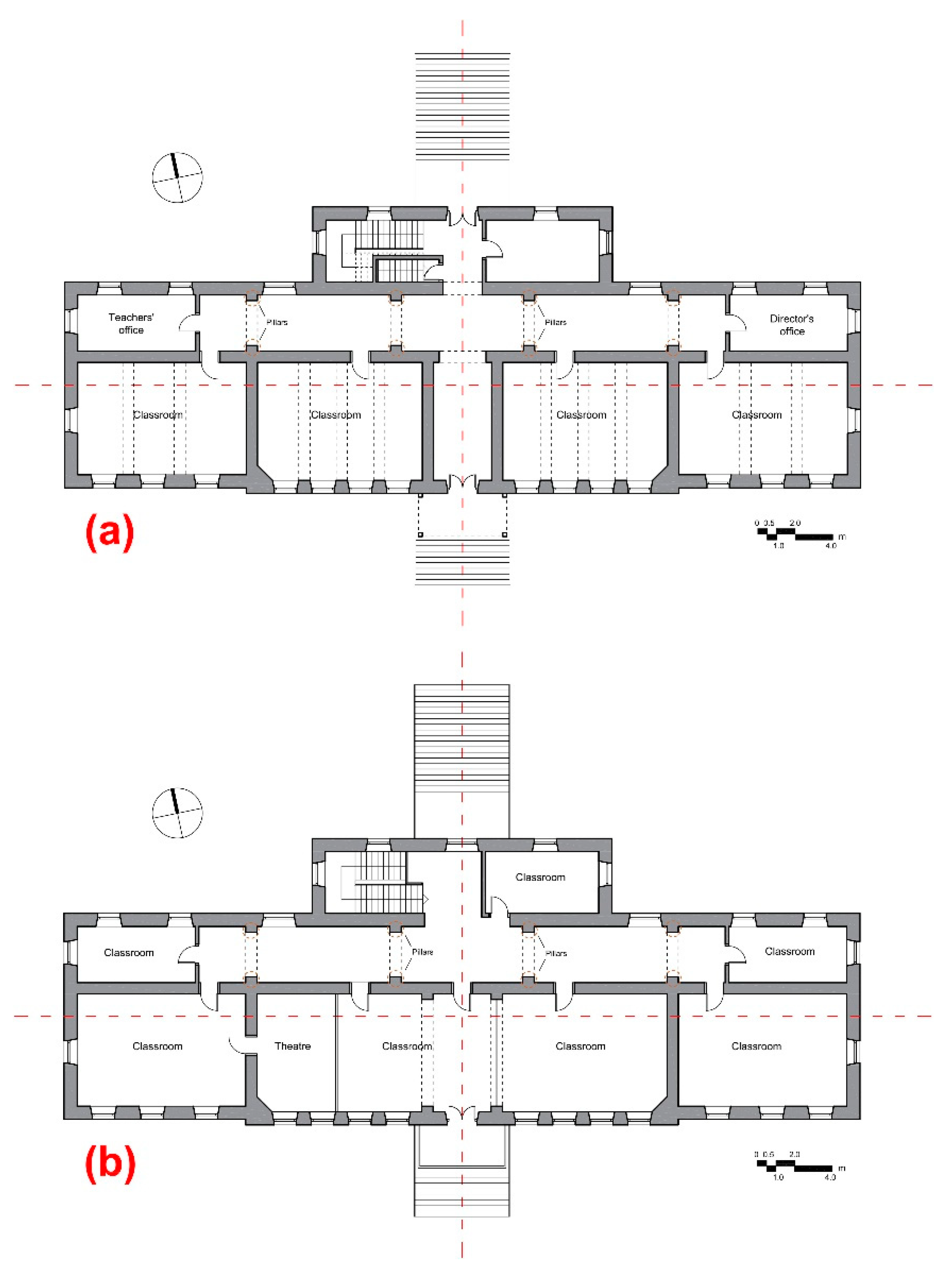
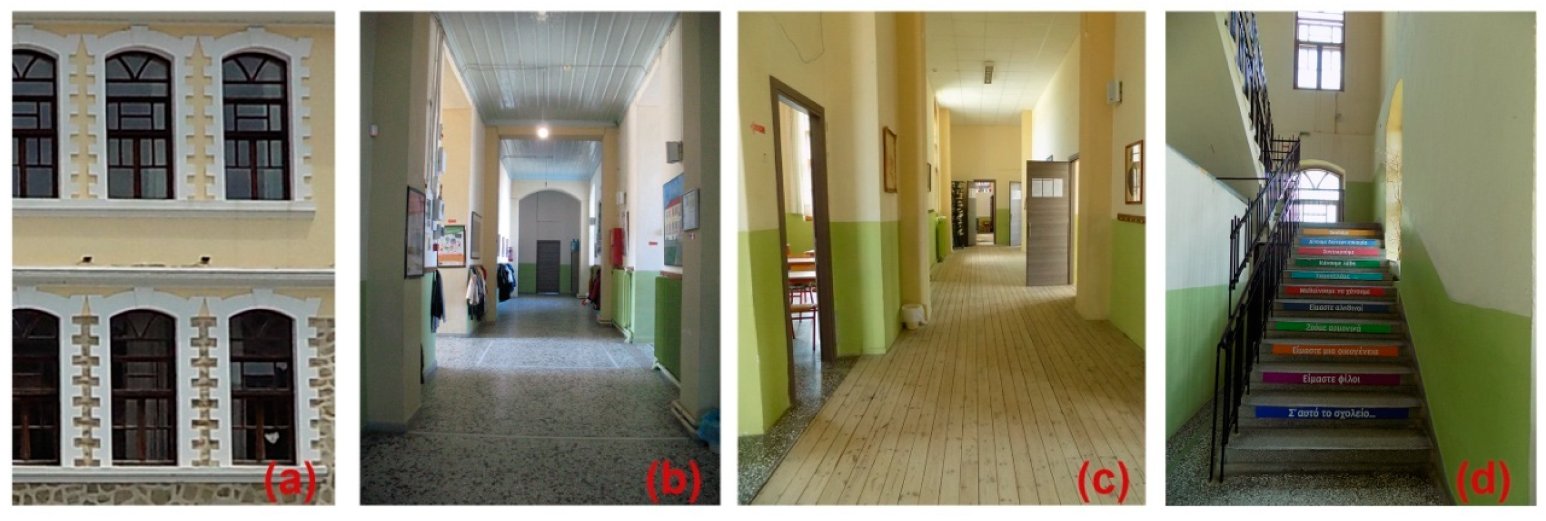
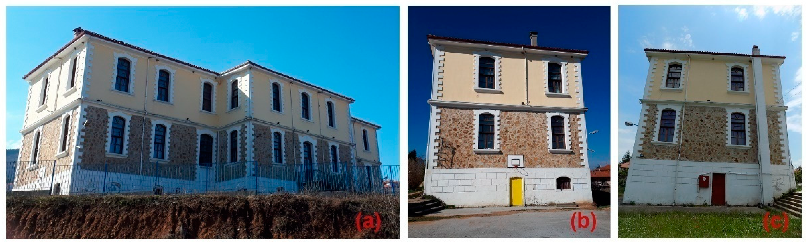
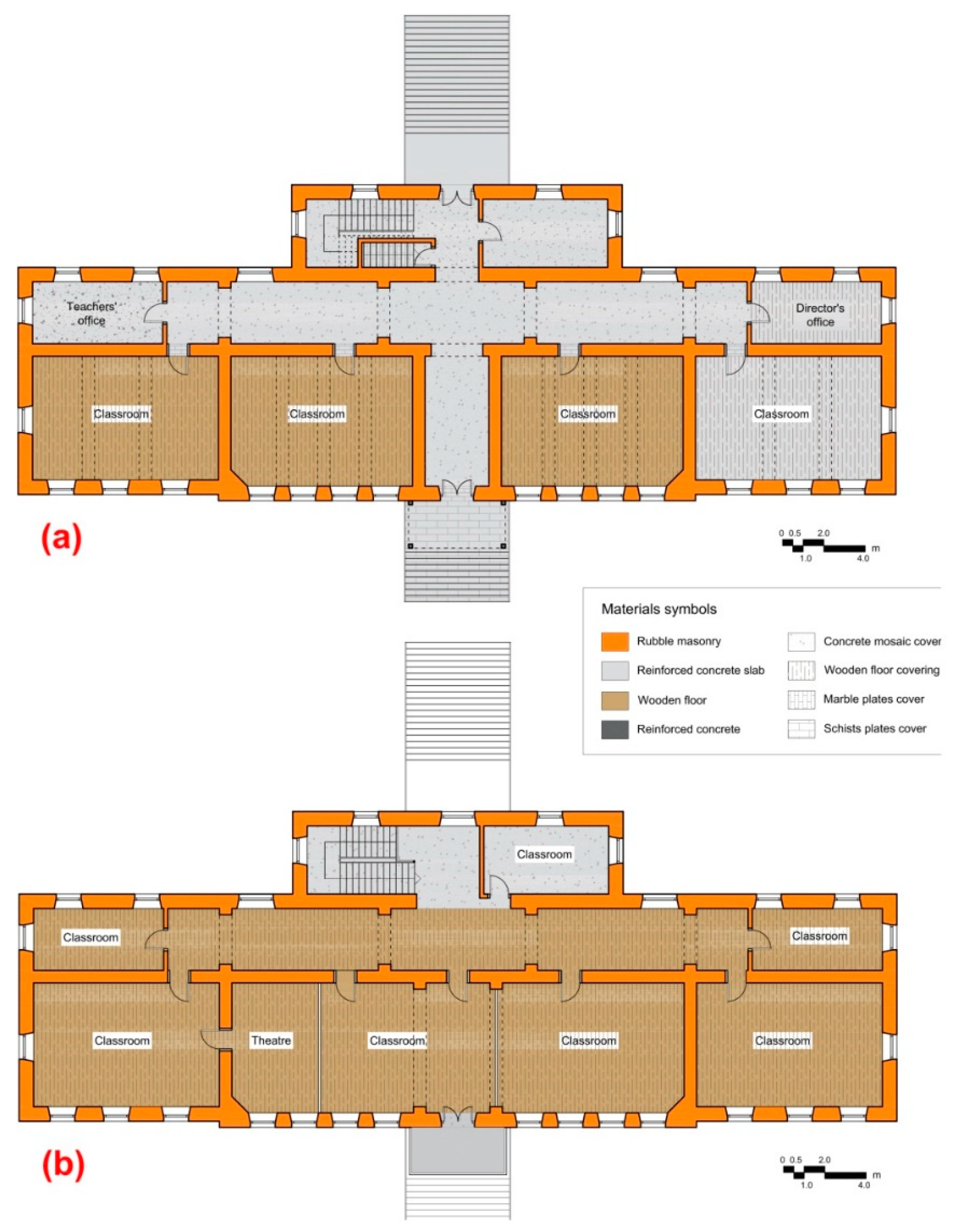
3.2. Architectural Aspects
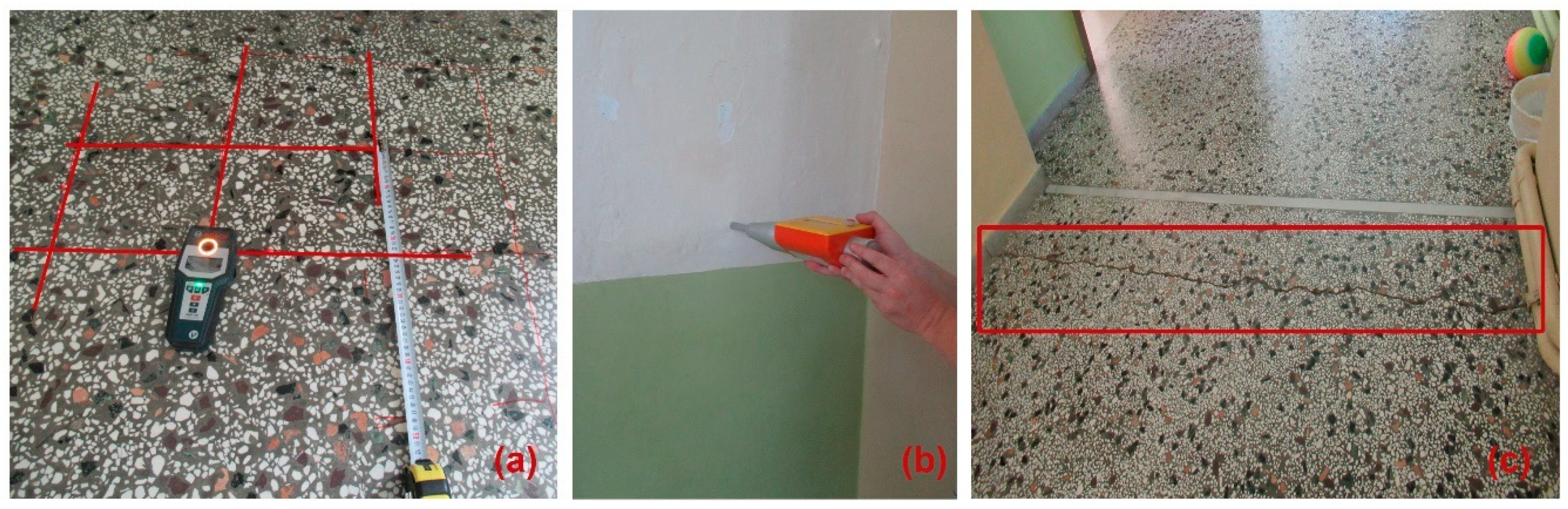
3.3. Constructional Aspects
3.4. Structural Assessment
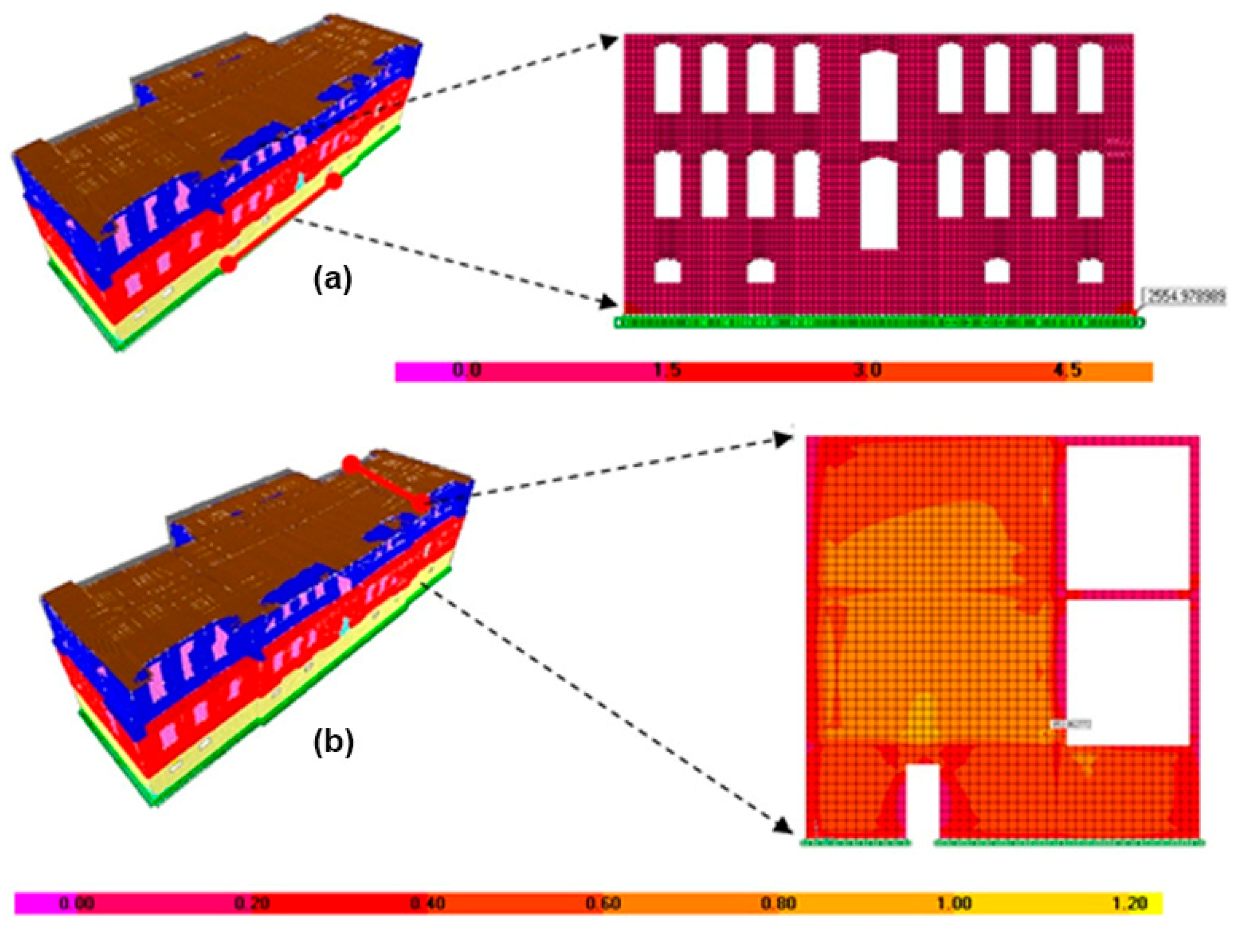
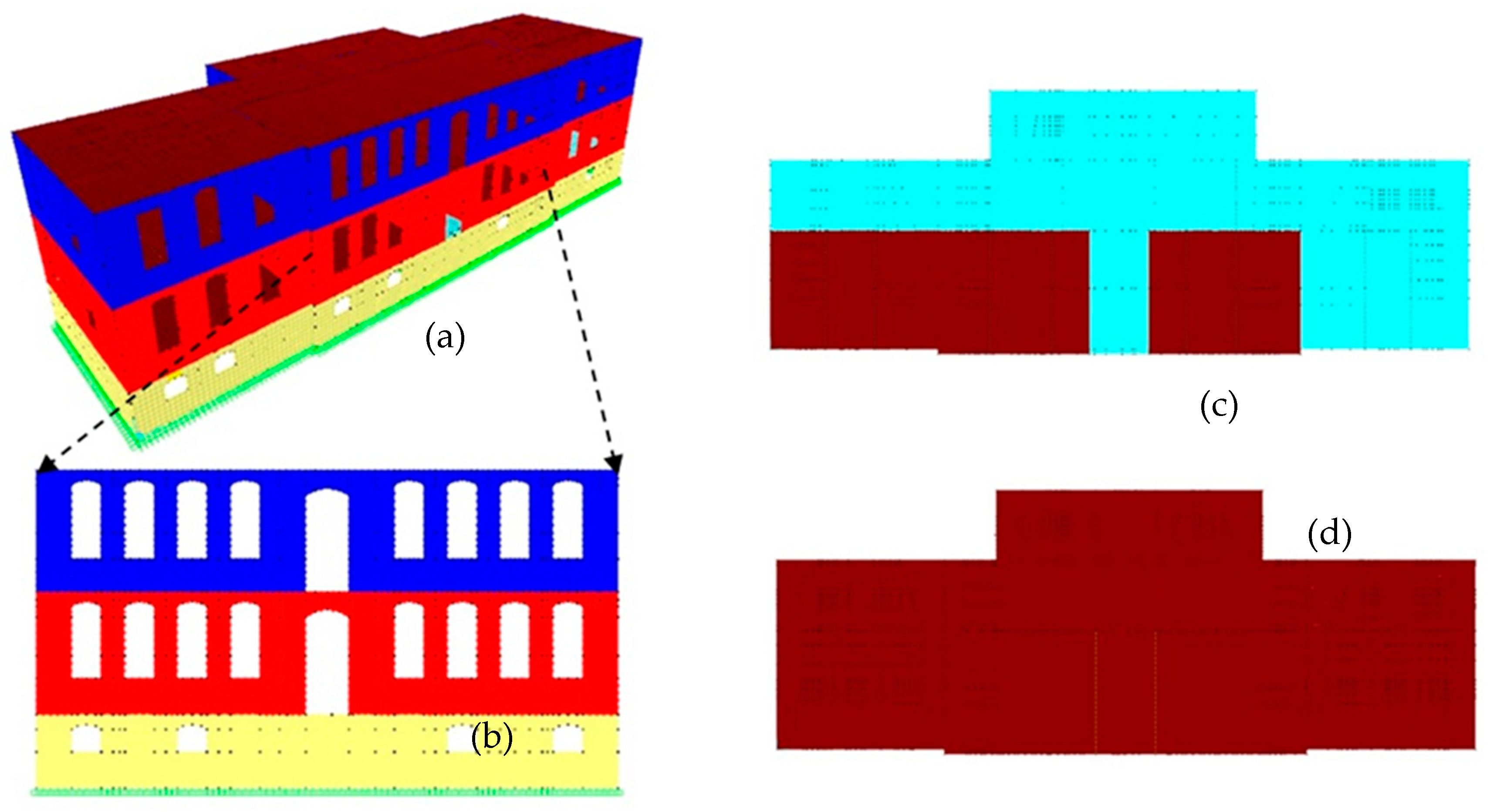
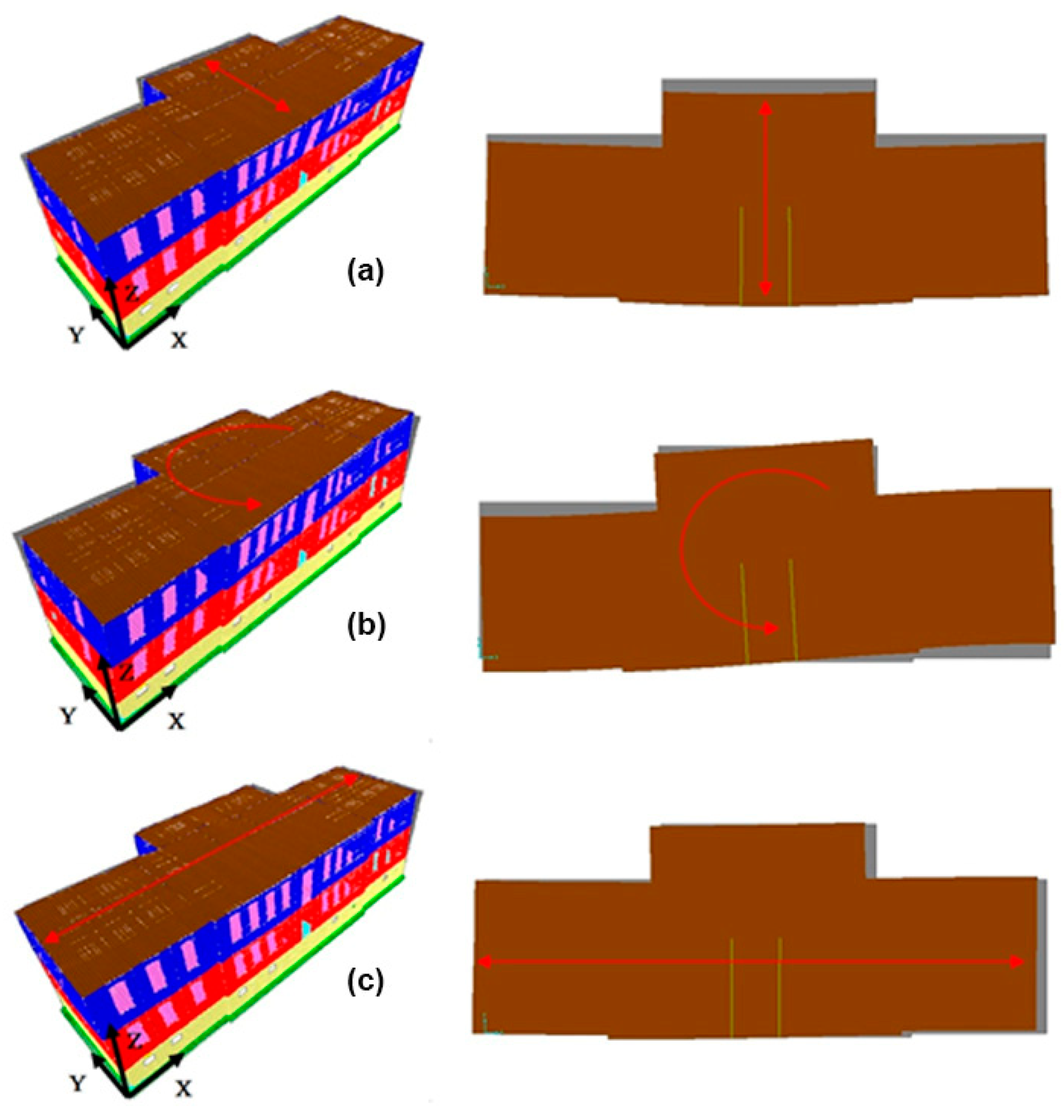
3.4.1. Finite Element Model
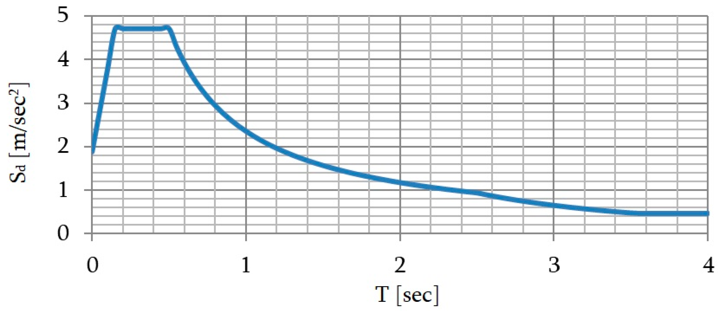
3.4.2. Actions and Ultimate Limit Design Situations
- :
- the permanent, variable and seismic actions, respectively;
- :
- the combinations value of a variable action;
- :
- the quasi-permanent value of a variable action;
- :
- the partial factors corresponding to the permanent and variable actions, respectively.
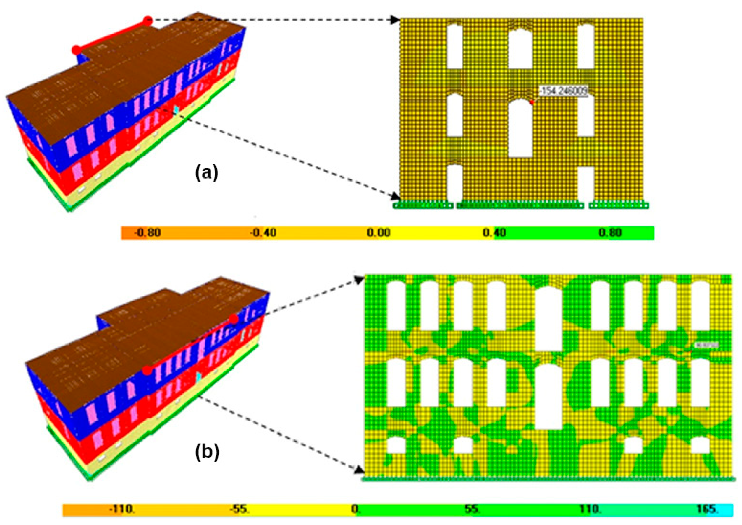
3.4.3. Persistent and Seismic Design Situations
4. Conclusions
Author Contributions
Funding
Institutional Review Board Statement
Informed Consent Statement
Data Availability Statement
Acknowledgments
Conflicts of Interest
References
- Arya, A.S. Protection of Educational Buildings Against Earthquakes, a Manual for Designers and Builders; Unesco: Bankok, Thailand, 1987. [Google Scholar]
- Abreu Marques, B.; de Brito, J.; Correia, J.R. Constructive characteristics and degradation condition of Liceu Secondary Schools in Portugal. Int. J. Archit. Herit. 2015, 9, 896–911. [Google Scholar] [CrossRef]
- Guarini, M.R.; Morano, P.; Sica, F. Historical school buildings. Amulti-criteria approach for urban sustainable projects. Sustainability 2020, 12, 1076. [Google Scholar] [CrossRef] [Green Version]
- Salvado, F.; Marquesde Almeida, N.; Vale, E.; Azevedo, A. Historical analysis of the economic life-cycle performance of public school buildings. Build. Res. Inf. 2019, 47, 813–832. [Google Scholar] [CrossRef]
- Lassandro, P.; Cosola, T.; Tundo, A. School building heritage: Energy efficiency, thermal and lighting comfort evaluation viavirtual tour. Energy Procedia 2015, 78, 3168–3173. [Google Scholar] [CrossRef] [Green Version]
- Martinez-Molina, A.; Boarin, P.; Tort-Ausina, I.; Vivancos, J.L. Post-occupancy evaluation of a historic primary school in Spain: Comparing PMV, TSV and PD for teachers’ and pupils’ thermal comfort. Build. Environ. 2017, 117, 248–259. [Google Scholar] [CrossRef]
- Carofilis, W.; Perrone, D.; O’ Reilly, G.J.; Monteiro, R.; Filiatrault, A. seismic retrofit of existing school buildings in Italy: Performance evaluation and loss estimation. Eng. Struct. 2020, 225, 111243. [Google Scholar] [CrossRef]
- Buvik, K.; Andersen, G.; Tangen, S. Ambitious renovation of a historical school building in cold climate. Energy Procedia 2014, 48, 1442–1448. [Google Scholar] [CrossRef] [Green Version]
- Watters, D.M. Our catholic school: Themes and patterns in early catholic school buildings and architecture before 1872. Innes Rev. 2020, 71, 1–66. [Google Scholar] [CrossRef]
- Perrone, D.; O’ Reilly, G.J.; Monteiro, R.; Filiatrault, A. Assessing seismic risk in typical Italian school buildings: From in-situ survey to loss estimation. Int. J. Disaster Risk Reduct. 2019, 44. [Google Scholar] [CrossRef]
- Khledj, S.; Bencheikh, H. Impact of a retrofitting project on thermal comfort and energy efficiency of a historic school in Miliana, Algeria. Int. J. Archit. Herit. 2019. [Google Scholar] [CrossRef]
- Francois, L. The Right to Education from Proclamation to Achievement 1948–1968; Unipub, Inc.: New York, NY, USA, 1968. [Google Scholar]
- Freeman, K.J. Schools of Hellas: An Essay on the Practice and Theory of Ancient Greek Education from 600 to 300; Rendall, M.J., Ed.; Macmillan and Co Limited: London, UK, 1912. [Google Scholar]
- Dascalaki, E.G.; Sermpetzoglou, V.G. Energy performance and indoor environmental quality in Hellenic schools. Energy Build. 2011, 43, 718–727. [Google Scholar] [CrossRef]
- Doukas, D.I.; Bruce, T. Energy Audit and renewable integration for historic buildings: The case of Craiglockhart Primary School. Procedia. Environ. Sci. 2017, 38, 77–85. [Google Scholar] [CrossRef]
- Galimullina, A.; Korotkova, S. Adapting the Architecture of School Buildings in the Context of Humanizing the Environment. In Proceedings of the IOP Conference Series: Materials Science and Engineering, Kazan, Russia, 29 April–15 May 2020. [Google Scholar]
- Kalafati, E. The school buildings of the elementary education 1821–1929. In Historic Archives of Greek Youth; General Secretariat for Youth: Athens, Greece, 1988. [Google Scholar]
- Pantazis, C. Mass Education and Economic Development in Greece: The Educational Reform of 1929. Ph.D. Thesis, University of Ioannina, Ioannina, Greece, June 2010. [Google Scholar]
- Lerma, C.; Mas, A.; Blasco, V. Analysis procedure of a previous planning organization: The area of the Seminary School of Corpus Christi in Valencia, Spain. Int. J. Archit. Herit. 2013, 7, 135–152. [Google Scholar] [CrossRef] [Green Version]
- Kokkonis, I.P. Summary of the Report Given to the Commission on Primary Instruction Concerning the Manual for the Mutual-Method Schools of France; Sarazin, J., Ed.; Egina, Greece, 1831. [Google Scholar]
- Moraitis, S. Διδασκαλική: ή σύντομοι οδηγίαι περί της χρήσεως της νέας διδασκαλικής μεθόδου. Βιβλιοθήκη του προς Διάδοσιν των Ελληνικών Γραμμάτων Συλλόγου. 45, Σύλλογος προς Διάδοσιν των Ελληνικών Γραμμάτων. Vlastou Editions: Athens, Greece, 1880. (In Greek) [Google Scholar]
- Kardamitsi-Adami, M.D. Kallias and the School Building; National Technical University of Atnens: Athens, Greece, 1986. [Google Scholar]
- Karantinos, P. The New School Buildings; Technical Chamber of Greece: Athens, Greece, 1938. [Google Scholar]
- Pachta, V.; Papayianni, I. The study of the historic buildings of eclecticism in Thessaloniki under the prism of sustainability. Procedia Environ. Sci. 2017, 38, 274–282. [Google Scholar] [CrossRef]
- Pachta, V.; Papayianni, I. Natural and Anthropogenic Hazards and Sustainable Preservation. In 10th International Symposium on the Conservation of Monuments in the Mediterranean Basin, Natural and Anthropogenic Hazards and Sustainable Preservation; Springer: Berlin/Heidelberg, Germany, 2019; pp. 407–413. [Google Scholar]
- Papayianni, I.; Pachta, V.; Milosi, A. The survey of a historical building from the beginning of the previous century. Evaluation of mechanical characteristics of the load bearing system. In Proceedings of the 6th International Conference on Concrete Repair, Thessaloniki, Greece, 20–23 June 2016; pp. 353–360. [Google Scholar]
- Debailleux, L. Schmidt hammer rebound hardness tests for the characterization of ancient fired claybricks. Int. J. Archit. Herit. 2019, 13, 288–297. [Google Scholar] [CrossRef]
- Hüblová, S.; Cikrle, P.; Karel, O.; Kocáb, D. Experimental Measurement of the Diameter and Cover Depth of Steel Reinforcement using an Electromagnetic Concrete Cover Meter. In Proceedings of the IOP Conference Series: Materials Science and Engineering, Zuberec, Slovakia, 29–31 May 2019. [Google Scholar]
- Pavlides, S.B.; Tranos, M.D. Structural characteristics of two strong earthquakes in the North Aegean: Ierissos (1932) and Agios Efstratios (1968). J. Struct. Geol. 1991, 13, 205–214. [Google Scholar] [CrossRef]
- Pachta, V.; Papayianni, I. Design and application of a data system for the comparative study of historic mortars. In Lecture Notes in Computer Science (Including subseries Lecture Notes in Artificial Intelligence and Lecture Notes in Bioinformatics); Ioannides, M., Ed.; Springer: Berlin/Heidelberg, Germany, 2016; pp. 701–710. [Google Scholar]
- American Concrete Institute. 1R-03 (2003): In-Place Methods to Estimate Concrete Strength; American Concrete Institute: Indianapolis, IN, USA, 2003. [Google Scholar]
- Castellazzi, G.; D’ Altri, A.M.; de Miranda, S.; Ubertini, F. An innovative numerical modeling strategy for the structural analysis of historical monumental buildings. Eng. Struct. 2017, 132, 229–248. [Google Scholar] [CrossRef]
- Terzi, G.V.; Ignatakis, E.C. Non linear finite element analyses for the restoration study of Xana, Greece. Eng. Struct. 2018, 167, 96–107. [Google Scholar] [CrossRef]
- Betti, M.; Vingoli, A. Numerical assessment of the static and seismic behavior of the basilica of Santa Maria all’ Impruneta (Italy). Constr. Build. Mater. 2011, 25, 4308–4324. [Google Scholar] [CrossRef]
- Kita, A.; Cavalagli, N.; Masciotta, M.G.; Lourenço, P.B.; Ubertini, F. Rapid post-earthquake damage localization and quantification in masonry structures through multi dimensional non-linear seismic IDA. Eng. Struct. 2020, 219. [Google Scholar] [CrossRef]
- Bartoli, G.; Betti, M.; Marra, A.M.; Monchetti, S. On the role played by the openings on the first frequency of historic masonry towers. Bull. Earthq. Eng. 2020, 18, 427–451. [Google Scholar] [CrossRef]
- Wilson, A. Seismic Assessment of Timber Floor Diaphragms in Unreinforced Masonry Buildings. Ph.D. Thesis, The University of Auckland, Auckland, New Zealand, 2012. [Google Scholar]
- Denskovska, L.; Aleksovski, G.; Milkova, K.; Perunkosvski, K. The influence of in-plane stiffness of timber floors on the seismic response of existing masonry buildings. In Proceedings of the 16th European Conference on Earthquake Engineering, Thessaloniki, Greece, 15–21 June 2018. [Google Scholar]
- European Committee for Standardization EN 1996-1. Eurocode 6: Design of Masonry Structures—Part 1-1: General Rules for Reinforced and Unreinforced Masonry Structures; European Committee for Standardization: Brussels, Belgium, 2005. [Google Scholar]
- De Angelis, A.; Pecce, M. Seismic non structural vulnerability assessment in school buildings. Nat. Hazards 2015, 79, 1333–1358. [Google Scholar] [CrossRef]
- Napolitano, R.; Hess, M.; Glisic, B. Integrating non-destructive testing, laser scanning, and numerical modeling for damage assessment: The Room of the Elements. Heritage 2019, 2, 151–168. [Google Scholar] [CrossRef] [Green Version]
- SAP2000 v.11. Computers and Structures, Inc.: Berkeley, CA, USA, 2007. Available online: https://adicexan.mystrikingly.com/blog/sap-2000-advanced-v11-0-4-full-version-download (accessed on 25 December 2020).
- Marseglia, P.S.; Micelli, F.; Aiello, M.A. Analysis of equivalent diaphragm vault structures in masonry construction under horizontal forces. Heritage 2020, 3, 989–1107. [Google Scholar] [CrossRef]
- Manolis, G.D.; Makarios, T.K.; Terzi, V.; Karetsou, I. Mode shape identification of an existing three-story flexible steel stairway as a continuous dynamic system. Theor. Appl. Mech. 2015, 42, 151–166. [Google Scholar] [CrossRef]
- Ministerio de Fomento. Norma de Construcciòn Sismorresistente: Parte General y Edificaciòn (NCSE 02); Ministerio de Fomento: Madrid, Spain, 2002.
- ASCE 07-16. Minimum Design Loads and Associated Criteria for Buildings and Other Structures; American Society of Civil Engineers: Virginia, VA, USA, 2017. [Google Scholar]
- NTC-2008. Norme Tecniche per le Costruzioni. Official Gazette of the Italian Republic, 17 January 2018; N42. [Google Scholar]
- European Committee for Standardization EN 1998-1. Eurocode 8: Design of Structures for Earthquake Resistance—Part 1: General Rules, Seismic Actions and Rules for Buildings; European Committee for Standardization: Brussels, Belgium, 2004. [Google Scholar]
- Calvi, G. A displacement based approach for vulnerability evaluation of classes of buildings. J. Earth. Eng. 1999, 3, 411–438. [Google Scholar] [CrossRef]
- Catulo, R. Análise Dinâmica Experimental de Edifícios de Alvenaria e Avaliação Sísmica de um Edifício Tipo. Ph.D. Thesis, Tecnico Lisboa, Lisboa, Portugal, November 2015. [Google Scholar]
- The European Union. EN 1991: Eurocode 1-Actions on Structures; The European Union: Maastricht, The Netherlands, 2002. [Google Scholar]
- Hellenic Organization for Standardization. Greek National Annex to EN 1998-1. In Eurocode 8: Design of Structures for Earthquake Resistance—Part 1: General Rules, Seismic Actions and Rules for Buildings; Hellenic Organization for Standardization: Athens, Greece, 2005. [Google Scholar]
- European Committee for Standardization EN 1990. Eurocode—Basis of Structural Design; European Committee for Standardization: Brussels, Belgium, 2002. [Google Scholar]
- Wilson, E.L.; Button, M.R. Three-dimensional dynamic analysis for multi-component earthquake spectra. Earthq. Eng. Struct. Dyn. 1982, 10, 471–476. [Google Scholar] [CrossRef]


| Structural Element | Level | Schmidt Hammer Values | Compressive Strength Estimation * [MPa] |
|---|---|---|---|
| Masonry (renders-plasters) | Basement | 10–14 | <8 |
| Ground floor | 12–16 | <8 | |
| 1st floor | 10–20 | <8 | |
| External masonry (stones) | Basement | 44–50 | 38–44 |
| Ground floor | 45–50 | 36–44 | |
| R/C slab | Ground floor | 40–45 | 28–36 |
| 1st floor | 40–45 | 28–36 | |
| R/C staircase (with mosaic) | - | 40–45 | 28–36 |
| R/C staircase (without mosaic) | - | 20–24 | 10–13 |
| Element | Thickness [m] | Modulus of Elasticity [GPa] | Weight Per Unit Volume [kΝ/m3] | Poisson’s Ratio[-] | |
|---|---|---|---|---|---|
| Masonry | Basement | 0.85 | 4.489 | 25 | 0.2 |
| Ground floor | 0.77 | ||||
| 1stfloor | 0.55 | ||||
| R/C beams | Basement | 0.6 × 0.40 | 26 | 25 | 0.2 |
| Ground and 1stfloor | 0.6 × 0.30 | ||||
| R/C plate | 0.2 | 26 | 25 | 0.25 | |
| Wooden plate | 0.23 | 6 | 8 | 0.2 | |
| Reference | Value [sec] | |
|---|---|---|
| ASCE 07-16 [45] | 0.3127 | |
| Catulo [49] | 0.1922 | |
| NTC-2008 [46] | 0.3204 | |
| EN 1998 [47] | 0.3204 | |
| NCSE-2002 [44] | 0.1244 | |
| Calvi [48] | 0.2563 |
| Action | Value | |
|---|---|---|
| Permanent | Masonry self-weight | 25 [kΝ/m3] |
| Concrete self-weight | 25 [kΝ/m3] | |
| Wooden floor self-weight | 8 [kΝ/m3] | |
| Mosaic floor self-weight | 1.8 [kΝ/m2] | |
| Wooden roof trusses | 0.3 [kΝ/m2] | |
| French type tiles | 0.5[kΝ/m2] | |
| Plasterboard | 0.085[kΝ/m2] | |
| Variable | Student congregation, furniture, etc. | 3.5 [kΝ/m2] |
| Snow | 0.625 [kΝ/m2] | |
| Wind | 0.648 [kΝ/m2] | |
| Design Situation | Load Combination |
|---|---|
| Persistent | |
| Seismic | |
| Design Situation | Load Combination | ||
|---|---|---|---|
| Persistent | −122.271 | 60.958 | |
| −101.647 | 56.281 | ||
| −154.260 | 90.937 | ||
| −101.540 | 67.964 | ||
| Seismic | 1454.238 | 529.324 | |
| 1620.110 | 474.579 | ||
| 1068.433 | 556.174 | ||
| 1620.110 | 524.016 | ||
| 2554.979 | 492.370 | ||
| 2554.979 | 536.110 | ||
| 1645.447 | 338.09 | ||
| 2554.979 | 853.803 |
Publisher’s Note: MDPI stays neutral with regard to jurisdictional claims in published maps and institutional affiliations. |
© 2020 by the authors. Licensee MDPI, Basel, Switzerland. This article is an open access article distributed under the terms and conditions of the Creative Commons Attribution (CC BY) license (http://creativecommons.org/licenses/by/4.0/).
Share and Cite
Pachta, V.; Terzi, V.; Malandri, E. Architectural, Constructional and Structural Aspects of a Historic School in Greece. The Case of the Elementary School in Arnaia, Chalkidiki. Heritage 2021, 4, 1-19. https://doi.org/10.3390/heritage4010001
Pachta V, Terzi V, Malandri E. Architectural, Constructional and Structural Aspects of a Historic School in Greece. The Case of the Elementary School in Arnaia, Chalkidiki. Heritage. 2021; 4(1):1-19. https://doi.org/10.3390/heritage4010001
Chicago/Turabian StylePachta, Vasiliki, Vasiliki Terzi, and Evangeli Malandri. 2021. "Architectural, Constructional and Structural Aspects of a Historic School in Greece. The Case of the Elementary School in Arnaia, Chalkidiki" Heritage 4, no. 1: 1-19. https://doi.org/10.3390/heritage4010001