1. Introduction
A virtual cathode is space-charge-induced potential distribution that appears, to the charged particles, as a real cathode. Its effect becomes significant when the current of the charged particle beam exceeds a certain value [
1,
2,
3]. Virtual cathode oscillation is a kind of periodic vibration in the amplitude and position of the virtual cathode. It is considered the source of microwave radiation from a device called a virtual cathode oscillator [
4,
5,
6,
7,
8,
9,
10,
11,
12,
13,
14,
15].
For a one-dimensional steady-state virtual cathode, a previous publication [
1] has summarized most of the important physical concepts and mathematical formulation. However, for virtual cathode oscillation, there exists no satisfactory theory or model that can fully describe the time-dependent virtual cathode behavior, let alone its interaction with the microwaves.
In recent years, computer simulation has become a very effective tool for solving physical and engineering problems. Like in many other fields, we can apply this numerical tool to virtual cathode oscillation, which may allow us to overcome the difficulty that is caused by the complexity of the system. This tutorial article serves as a guiding document for the explanation and demonstration of a one-dimensional numerical simulation of virtual cathode oscillation.
For particle-beam- or plasma-related studies, there are commercially available software products that can be used to carry out multi-dimensional, electromagnetic, and relativistic particle-in-cell (PIC) simulations. These simulation tools are critical nowadays for the design and improvement of experimental devices, so they are considered essential for most of the research and development. The one-dimensional simulation described in this article is by no means an attempt to replace these software products in any way. Instead, it is intended as a supplement to the steady-state theory published in another tutorial article [
1]. In addition, it is aimed at providing some general knowledge on numerical practices for students and young researchers.
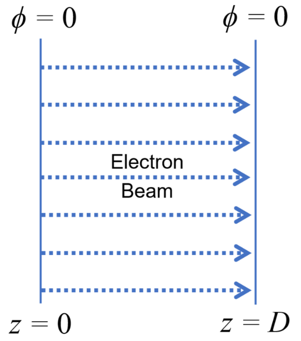
The model of interest is shown in
Figure 1. A uniform electron beam is injected into a drifting space defined by two parallel planes of equal electric potential. The drifting space is an ideal vacuum, and the injected electrons are the only particle species considered. The beam has a constant current density, and all electrons have the same initial kinetic energy. If we assume that the vertical size of the electron beam is much larger than the width of the drifting space, we can treat this situation in a one-dimensional manner.
Obviously, there is no experimental system that is truly one-dimensional. However, as in the steady-state analysis [
1], one-dimensional approximation is a very important approach through which we can expect to achieve a better understanding of the process and further establish logical relations between some key parameters. In fact, from the physical point of view, we can consider multi-dimensional effects as quantitative deviations from the one-dimensional nature of the phenomenon.
Another approximation here is the omission of the magnetic field. Precisely speaking, charged particles interact with each other not only electrically but also magnetically, because charged particle movement generates a magnetic field. In addition, a magnetic field must be involved if we want to consider the interaction between the electron beam and the electromagnetic waves. However, for the space-charge-dominated one-dimensional model without considering microwave interaction, it is reasonable to assume that the magnetic field is not playing any important role here. In other words, the simulation model described in this article is electrostatic, which means that the electric potential is well defined at any point by the electric field and the boundary condition. It is noted that the electric field does indeed change in time, although Maxwell’s electromagnetic induction is not considered.
The basic equations and boundary conditions are given in
Section 2 and are similar to those used in the steady-state theory [
1] except for allowing the time dependency of every parameter and removing the connection between electron kinetic energy and electric potential.
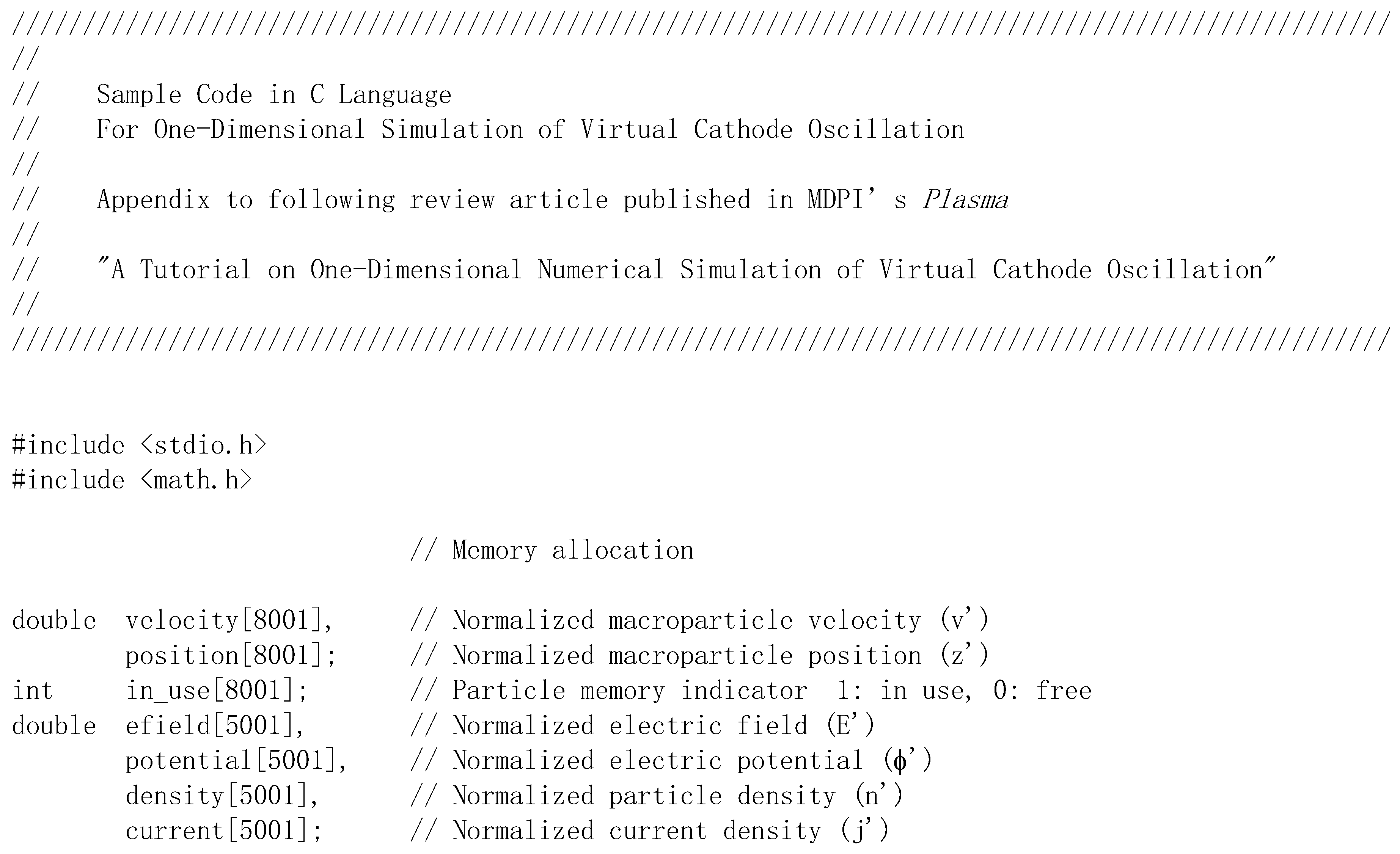
Section 3 describes the detailed methods for numerically solving the differential equations. Some additional explanations of the sample code, which is attached in
Appendix A, are given in
Section 4. Finally,
Section 5 contains some examples of the simulation results, with brief discussions.
2. One-Dimensional Model
Consider the situation shown in
Figure 1, where an electron beam with constant initial electron kinetic energy and constant beam current density is injected into a drifting space. The width of the drifting space is D, and both boundaries are grounded. This is the same situation as that described in Section 3 of Ref. [
1]. Apparently, for observing virtual cathode behavior, the injected beam current density must be higher than that given by Equation (51) of Ref. [
1].
2.1. Basic Equations and Boundary Conditions
Electrostatic, non-relativistic, one-dimensional equations are shown below. They are mainly the Poisson equation for the fields and the equation of motion for the electrons.
Here,
E,
ϕ,
n,
v,
z, and
t represent the electric field, electric potential, electron density, electron velocity, spatial position, and time, respectively. In addition, the constants
e,
m, and
ε0 are the unit charge, electron mass, and vacuum permittivity, respectively.
Compared with the steady-state model described in [
1], it is worth noticing that the electron velocity is no longer linked with the electric potential, allowing different electrons with different velocities to exist at the same location. In addition, a new variable (
t) has been introduced in order to allow for variation of the parameters with time.
The following are the boundary conditions.
(1) Both boundaries are grounded, namely
(2) The injected beam current density,
Jin, is constant:
where
nin and
vin are the initial electron density and velocity, respectively.
(3) Each injected electron has a constant initial kinetic energy of
eV0, so the initial non-relativistic electron velocity is given by
2.2. Parameter Normalization
In order to normalize the parameters, we define the following normalization constants.
Here,
d is defined by the following relation for given values of
Jin and
V0:
The above equation indicates that d corresponds to the length of a space-charge-limited gap where an electron beam of current density Jin is accelerated by voltage V0.
Using the normalization constants of Equations (8)–(14), we can define the dimensionless quantities
E′,
ϕ′,
n′,
J′,
v′,
z′, and
t′ by using
and, by submitting them into Equations (1)–(4), we obtain the following equations.
In addition, the boundary conditions of Equations (5)–(7) are transformed to
where
D′ =
D/
d.
Furthermore, by using the expression for plasma frequency
together with Equations (6), (7) and (15), Equation (14) can also be written as
This relation will be used later when we compare the oscillation frequency with the plasma frequency.
The numerical simulation described in this article is carried out only for the normalized parameters using Equations (23)–(26) with boundary conditions of Equations (27)–(29). In order to visualize the simulation results in physical quantities, one has to convert the normalized parameters to real parameters by using Equations (16)–(22). Since the condition factors, presumably V0 and Jin (which is represented by d through Equation (15)), only appear in the normalization relations, the simulation results for the normalized parameters can be considered general. In other words, if V0 or Jin changes, there is no need to rerun the simulation, we only need to reflect the change in the normalization relation and interpret the simulation results again using the new coefficients. For this reason, the simulation results shown in this article are believed to be effective for wide ranges of V0 (within non-relativistic limits) and Jin.
3. Numerical Method
To numerically solve the differential equations of Equations (23) and (24), we need to divide the simulation space into many small divisions (Δz′), and, in each of these divisions, we assume that every physical parameter (such as the field or the potential) has a single value. In other words, the originally continuous distribution of the parameter is represented by a series of discrete values.
Similarly, to numerically solve the differential equations of Equations (25) and (26), we need to divide the simulation time duration into many small intervals (Δt′), and, during each of these intervals, we assume that every physical parameter (such as the particle velocity and the field) remains constant. In other words, the originally smooth variation of the parameter is represented by a sequence of discontinuous values.
With these assumptions, the differential Equations (23)–(26) are converted to the following difference equations, which can be solved numerically given proper boundary and initial conditions.
To be more specific, for a spatial division of index
j, Equations (32) and (33) can be written as
where
E′
j+1 and
E′
j are the electric field at either end of the division,
n′
j is the electron density, and
ϕ′
j+1 and
ϕ′
j are the electric potentials of this and the neighboring division, respectively.
On the other hand, for a particle of index
k, Equations (34) and (35) can be written as
where subscript “old” and “new” indicate the parameter value before and after the time interval Δ
t′, respectively, and
E′
k is the electric field acting on this particle. However, it is important to note that these equations are not solved for every electron, because their number is simply too large.
An important numerical approach commonly used in particle beam or plasma simulations is the concept of the so-called “macroparticle”. Because of the vast number of real particles (such as electrons or ions) in the real situation, which is absolutely hopeless for any computer to simulate, these particles are represented by a limited number of macroparticles; each of them embodies a large number of real particles, in this case being electrons. So, the difference equations of motion, Equations (38) and (39), are solved only for these macroparticles. Apparently, the more macroparticles we use, the better they can reproduce the real situation of a seemingly continuous electron beam.
To calculate
E′
k in Equation (38), we assume that the electric field varies linearly in each division from its value at one end (
E′
j) to that at the other end (
E′
j+1), which leads to
where
j is the division index in which the macroparticle exits. The reason for using Equation (40) is to take into account the macroparticle position inside the division, instead of just using one of the boundary values.
Using the above equations, the simulation tracks all macroparticles by calculating their velocity and position step by step. For every time step, the new position of each macroparticle is calculated, and its contribution to the charge and current density distributions is added to the local division using
where subscript
j is the division index in which the macroparticle is located, and
q′ is the normalized charge of one macroparticle. It may look a bit confusing, since
n′ is the number density, which is positive, but the sign of the second term in Equation (41) is minus because
q′ is negative.
Finally, it is necessary to find the boundary value of
E′ for a given distribution of
n′. From Equation (23), we have
Also, from Equations (24) and (27), we have
Using a partial integration formula, we can write
By combining Equations (43)–(45), we obtain
In the form of numerical integration, the above equation becomes
where
nspace is the total number of spatial divisions.
4. Programming Details
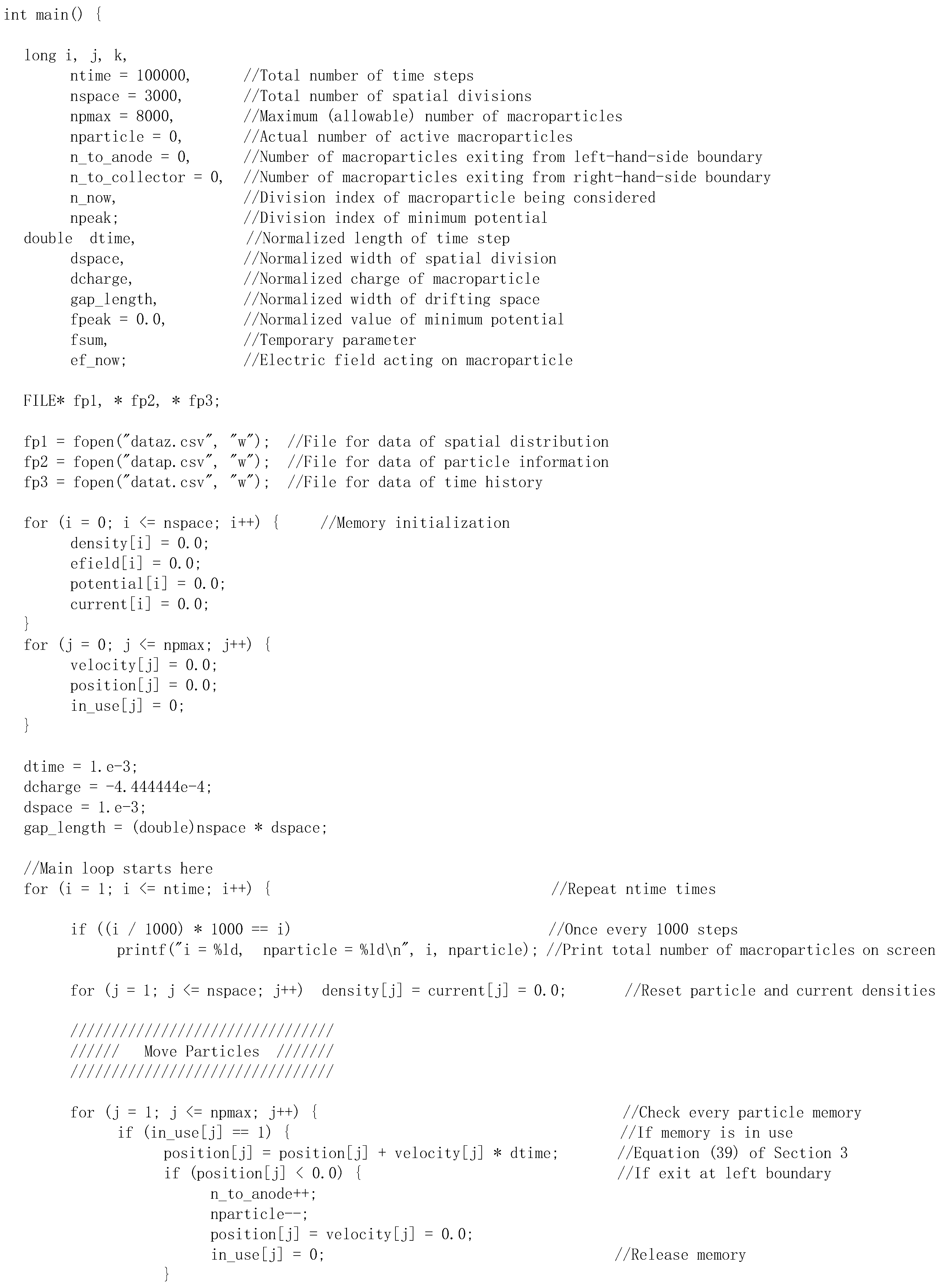
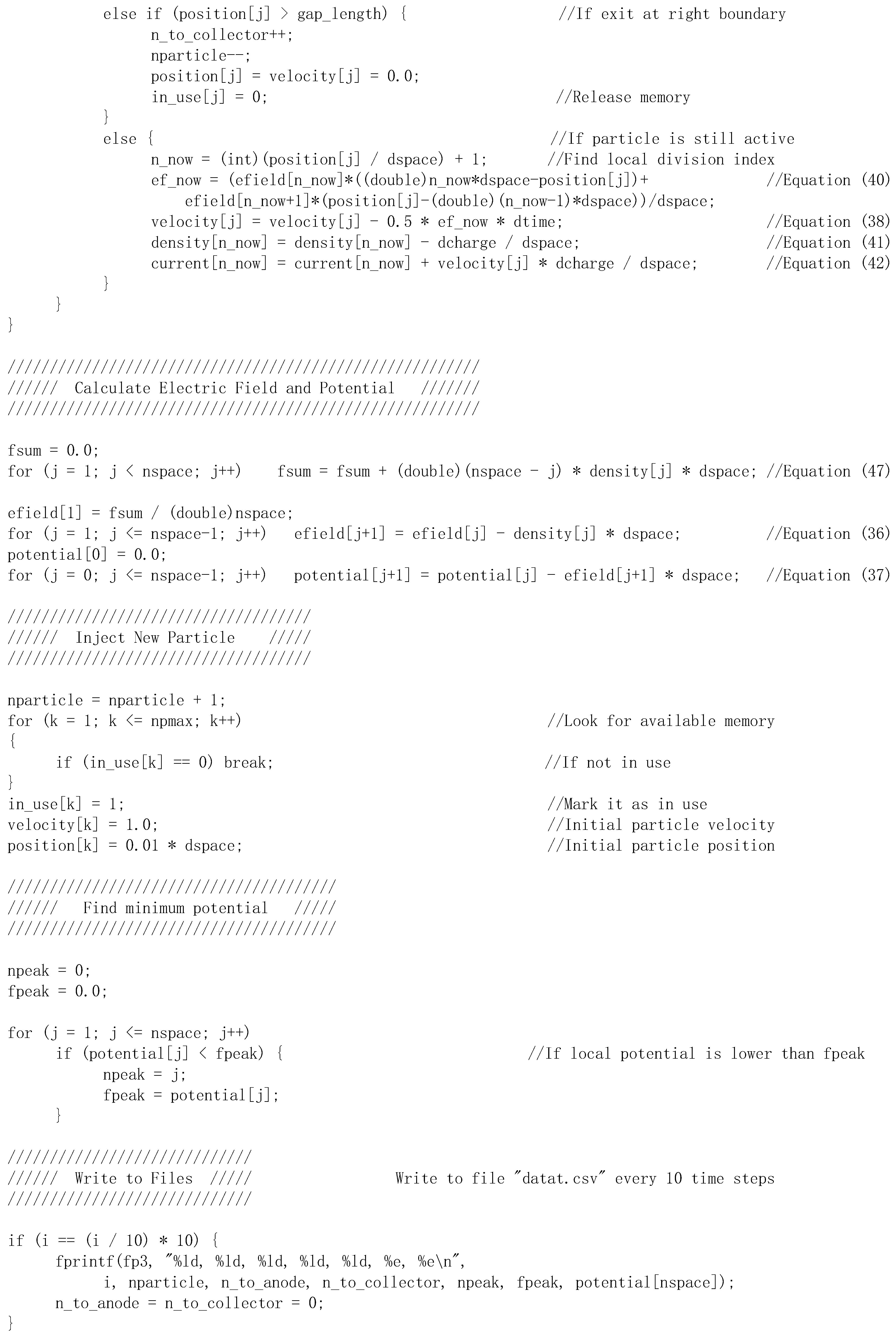
Based on the above-explained model and method, we can make a program for the numerical simulation. A sample code is shown in
Appendix A, which is written in the C language. There are, of course, many other computer languages that can be used for the same purpose.
The core of the simulation code is a loop for repetitive calculation, which represents the time evolution of the events, including the calculations of the spatial parameters (E′, ϕ′, and n′) and the particle parameters (v′ and z′). The initial condition starts from an empty space with no macroparticles inside. As time advances, macroparticles are injected from the boundary, and all the spatial and particle parameters are calculated step by step.
More specifically, for every cycle of the main loop, the following calculations are carried out.
- -
All active macroparticles in the simulation area are moved for one time step, using Equations (38) and (39).
- -
The particle density and current density profiles are obtained by using Equations (41) and (42), after all macroparticles are taken into account.
- -
The electric field and potential are calculated for every division, using Equations (36) and (37), with boundary values given by Equation (47).
- -
A new macroparticle is injected at the boundary.
Computer memory is required for storing all the spatial parameters and particle parameters separately. In the sample code, this memory is overwritten in every cycle of the main loop so that only the new values are stored for every spatial division and every macroparticle.
As macroparticle injections continue, their total number keeps increasing for a while at the beginning of the simulation. However, after a certain time, some macroparticles start exiting the region at either boundary, and the total number of active macroparticles starts to stabilize within a certain range. Therefore, the total number of active macroparticles is not predetermined, and its value may vary during the simulation process.
It is important to make sure that the total number of macroparticles does not overflow the computer memory that has been allocated by the simulation code. There are several possible ways to do this. In the sample code shown in
Appendix A, the memory resources are recycled by allowing new particles to reuse memory that has been released by particles that have already exited the region.
The following values are used in the sample code, although they are neither mandatory nor universal.
- (1)
Normalized time step, Δt′ = 10−3;
- (2)
Normalized spatial division, Δz′ = 10−3;
- (3)
Normalized macroparticle charge, q′ = J′in × Δt′= − 4/9 × 10−3.
Theoretically speaking, the smaller these values are, the more accurate the calculation results can be expected to be, although the calculation will consume more computer resources and computing time. Conversely, large values may lead to unexpected calculation errors or even calculation instability. For each of the above quantities, a critical value exists, which can be found by using numerical computation theory for a desired computation accuracy. However, in this tutorial article, we do not intend to go into the computation theory. We suggest a simpler approach instead. When we change one of the values by several times (or an order of magnitude), if the calculation results do not change noticeably, we can assume that the values we used are in the proper range. From this point of view, the values shown above are considered to be proper.
A more practical factor here is that the modern computers are very powerful and are equipped with a large quantity of fast memory; therefore, for the one-dimensional simulation described here, the computer resources and computation time are really not so important. In fact, depending on the computer environment, using the above values, an execution of the sample code (
Appendix A) can hardly take more than one minute.
The sample code given in
Appendix A has been tested for the following environments:
- -
Visual Studio 2022 (17.13) on Microsoft Windows 11;
- -
Visual Studio Code (1.97) on Microsoft Windows 11;
- -
Visual Studio Code (1.97) on MacOS Sequoia 15.3.
Depending on the operating system, the VS code needs an additional C-language extension and compiler.
5. Examples of Simulation Results
In the sample code, shown in
Appendix A of this article, the simulation results are written into several text files. The values of the time-varying parameters, including the total number of active macroparticles, numbers of macroparticles exiting at either boundary, and position and amplitude of the minimum potential, are saved once every 10 time steps. In addition, at the end of the simulation, the spatial parameters (
E′,
ϕ′,
n′, and
J′) and the particle parameters (
v′ and
z′) are saved in separate files. These files are convenient for visualizing the simulation results after the execution of the computation.
5.1. When Beam Current Density Is Relatively Low
This is the case described in Section 3.1 of Ref. [
1]. Here, “relatively low” means that the beam current is lower than the limiting value so that all electrons can go through the gap without reflection. In other words, there is no virtual cathode. If we assume that the limiting current density is
Jmax, from Equations (49) and (51) of Ref. [
1], we can write
The value of the above equation is determined by the gap width for a given injected beam current density. It can also be considered as the ratio of the injected current to the limiting value for a given gap width. In any case, this is the only free variable for which we can change its value in the simulation and see its effects on the results.
For example, when
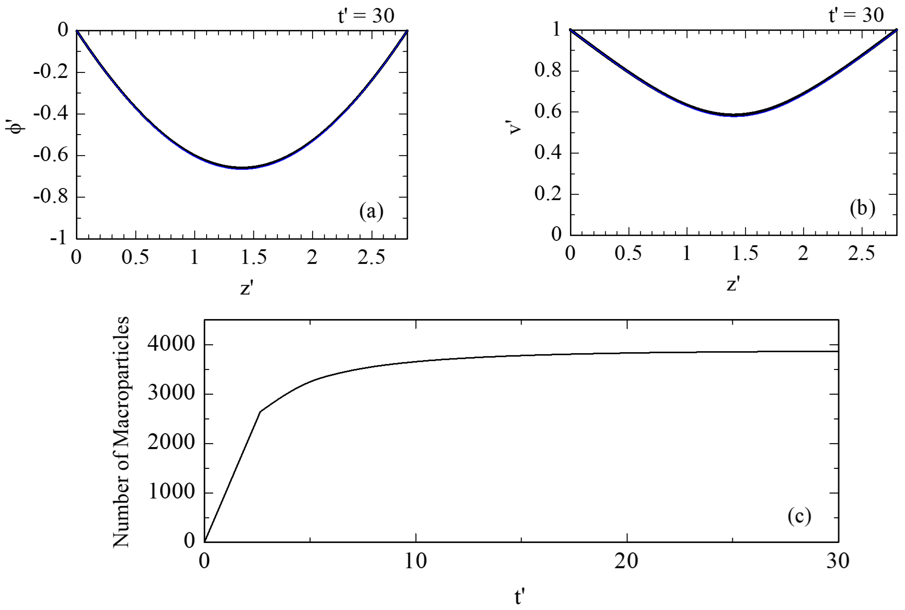
D′ = 2.8, the value of Equation (48) is smaller than 1, which means that the injected beam current density is “relatively low”. In this case, the simulation results are shown in
Figure 2. It can be seen from
Figure 2c that the total number of active macroparticles stabilizes near a fixed value after a certain time, when the status in the gap has reached a steady state. For the stabilized state, the spatial distributions of the electric potential and electron velocity are shown in
Figure 2a and
Figure 2b, respectively.
For comparison, the steady-state theoretical results [
1] are also shown with blue lines in
Figure 2a,b. In addition,
Figure 3 compares the relation between the injected beam current density (
Jin) and the potential minimum (
ϕp), where the theoretical curve is a replot of Figure 4 of Ref. [
1]. We see from these figures that the simulation results for the stabilized states (without a virtual cathode) agree well with the one-dimensional analytical theory, indicating that the simulation model is properly representing the physical phenomenon.
5.2. When Beam Current Density Is Higher Than the Limiting Value
To have the virtual cathode, we only need to let the value of Equation (48) be higher than 1, which corresponds to the situation described by Section 3.2 of Ref. [
1]. For example, when
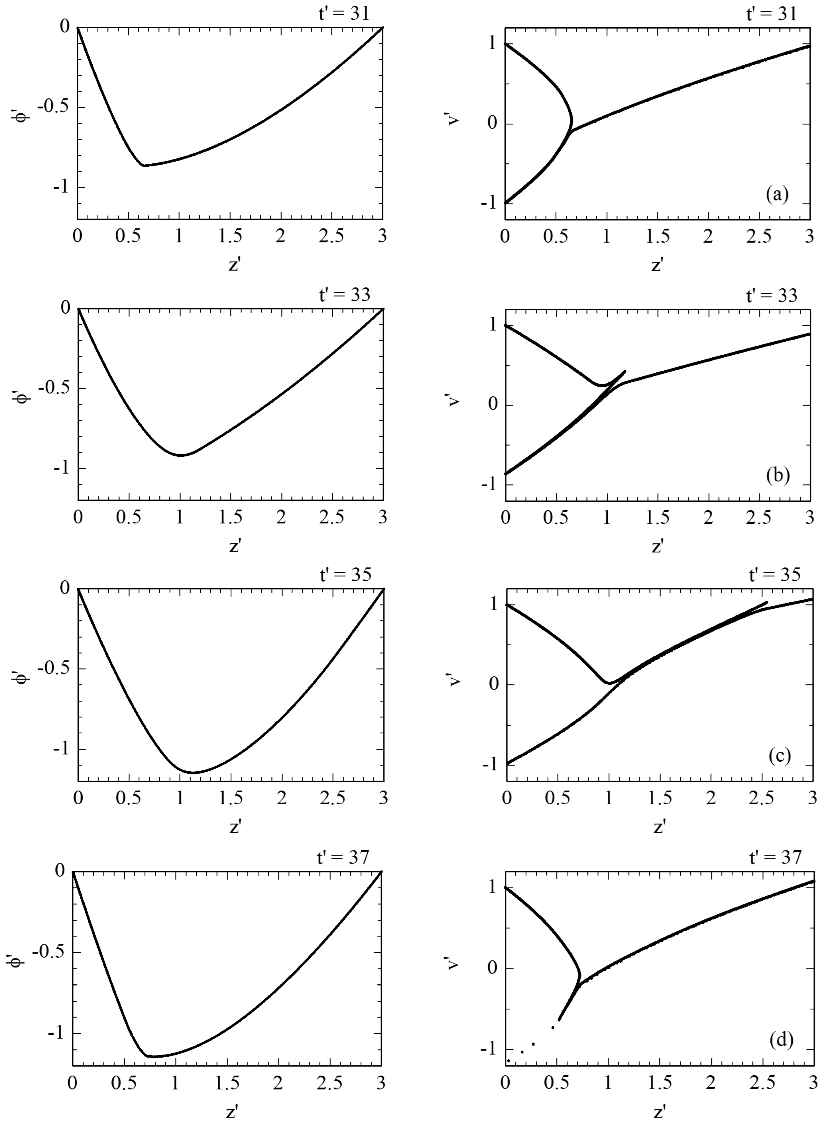
D′ = 3, the simulation results are as shown in
Figure 4. In order to visualize the time-dependent variation of the potential distribution and the particle phase-space distribution, these profiles are plotted for
t′ = 31, 33, 35, and 37 in
Figure 4a–d, respectively. In addition, the total number of active macroparticles is plotted in
Figure 4e, from which we can see clear periodic oscillation of a certain frequency. The virtual cathode behavior seen in
Figure 4 is certainly not what can be described by the steady-state theory. This is exactly why numerical simulation is required.
The time-dependent oscillation can be better seen in the Video Abstract. The video file (1D_VC.mp4) was made by combining the sample code with a Visual Studio C# Form. The C# part did nothing but display the simulation results on the screen, and the real-time frames were captured during the simulation by using the Xbox Game Bar on Windows 11.
During the virtual cathode oscillation, the reflected electron beam and the transmitted electron beam are both modulated. This can be seen from
Figure 5, where the time histories of the reflected current density (J
re) and transmitted current density (J
tr) are plotted. The strong modulation of the reflected beam is physically associated with microwave radiation from the virtual cathode oscillator [
14].
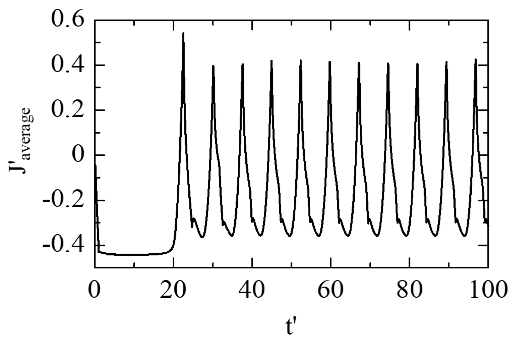
If the microwave interaction indeed occurs in the region between the virtual cathode and the injection plane, the average current density in this region should become important. Although the current density of each spatial division is known at any time, its average value across a certain region is not calculated in the sample code. Adding this calculation to the program is relatively simple, and the result obtained by a modified code is shown in
Figure 6. The reason for taking the average across the region between
z′ = 0 and
z′ = 1 is because the virtual cathode is generally found in the area near
z′ = 1, albeit oscillating. From
Figure 6, we see that the average current density starts at a value of about −4/9, which equals that of the injected beam. After the beginning of the virtual cathode oscillation, however, a large amplitude of oscillation is observed and the average value of the current is significantly reduced. This oscillating current is considered as a potential source of microwave radiation in the virtual cathode oscillator.
5.3. Oscillation Characteristics
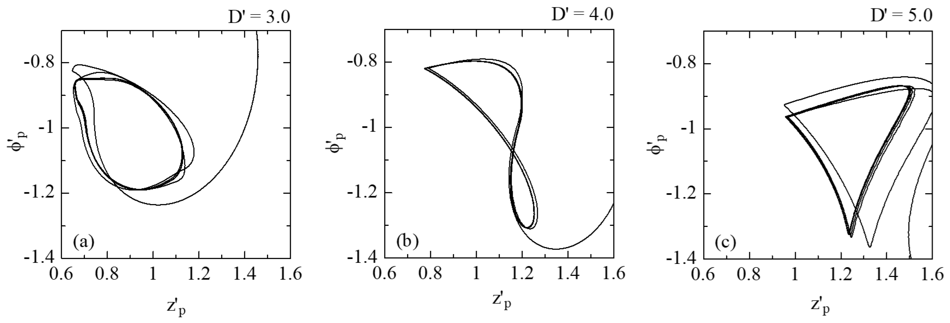
During the virtual cathode oscillation, the virtual cathode moves back and forth, and its amplitude oscillates up and down. As a result, for each cycle, the minimum potential (
ϕ′
p) and its position (
z′
p) draw a closed loop on the
ϕ′
p–
z′
p plane. It is interesting to note that the shape of this loop depends on the value of
D′, as shown in
Figure 7. This result qualitatively agrees with simulation results obtained back in the 1980s [
5].
From the simulation results shown in
Figure 5, we can find the time-averaged values for both
Jre/
Jin and
Jtr/
Jin. The results are shown in
Figure 8 by black and blue dots, respectively, that are compared with the steady-state theory [
1] shown by solid lines. For different simulation runs, the value of
D′ was changed, but this change was converted to that in
Jin/
Jmax by using Equation (48) for a better comparison with the theory.
Figure 8 tells us that the result of virtual cathode oscillation significantly reduces the reflected electron beam current while almost doubling the amplitude of the transmitted beam current.
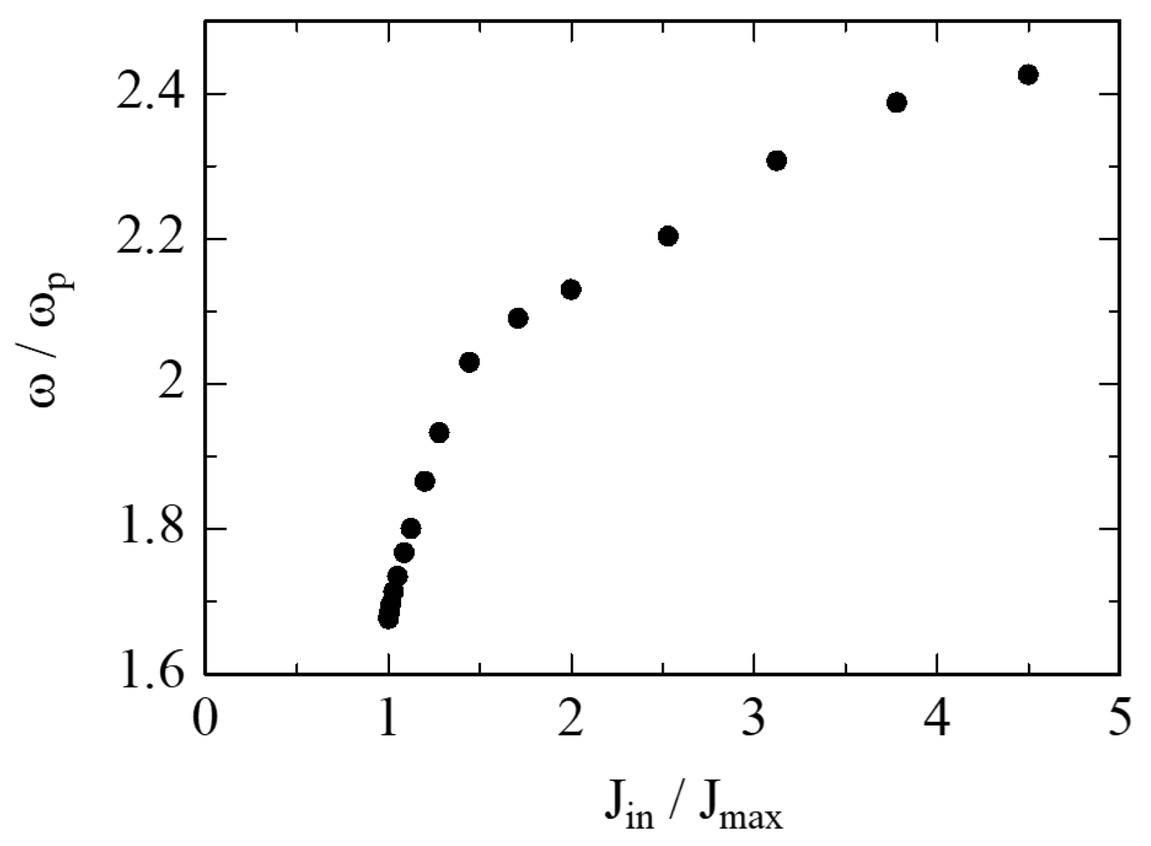
The oscillation frequency can be easily found by using the oscillation period. The results obtained with different values of
D′ are shown in
Figure 9, where Equation (31) was used in order to express the frequency in terms of ω
p. Like in
Figure 8, the values of D’ were converted to those of
Jin/
Jmax by using Equation (48) for practical purposes. As explained in
Section 2, the parameter normalization allows us to interpret the simulation results in a more general way. For example, the results shown in
Figure 9 tell us that virtual cathode oscillation should happen in an approximate frequency range of 1.6ω
p~2.5ω
p, as long as the one-dimensional and non-relativistic assumptions hold.
6. Conclusions
In this review article, a method of numerical simulation for one-dimensional virtual cathode oscillation was explained in detail. The basic equations are similar to those used in steady-state analytical theory, except for allowing for variation in the parameters with time and removing the connection between the electric potential and the electron velocity. The numerical methods were explained in a practical way, without involving computation theories for instability and accuracy.
A sample simulation program is attached as
Appendix A to this article. Some technical details regarding the sample code are described, as this article intends to help readers to fully understand the program and to encourage them to write their own codes for similar studies.
A video file is attached to this PDF, which provides a smooth view of the time-dependent variation shown in
Figure 4. It offers visual recognition for the phenomenon of virtual cathode oscillation.
The simulation approach described in this article is based on parameter normalization. Since most of the operational values that determine the condition (such as the voltage and the current) are hidden in the normalization relations, the simulation is considered general, which means that the results are effective for different condition parameters. For example, the one-dimensional simulation results given in this article tell us that, as the electron beam current increases, the transmitted beam current drops from ~40% to ~10% and the oscillation frequency increases from ~1.6ωp to ~2.5ωp.
This tutorial article guides readers through the process of one-dimensional simulation of virtual cathode oscillation. It has to be noted that the purpose of this article is more educational than scientific, because the model is so simplified that it is physically far away from any real situation we may encounter. Therefore, the simulation results obtained by this article can hardly be used to solve any real-world problem directly. The readers are specifically advised to keep in mind the following factors.
First, multi-dimensional effects are usually non-negligible. The one-dimensional approach described above is intended to demonstrate the method but not the results. Discrepancies are bound to occur in a real device, depending on how far its geometry is from what can be considered one-dimensional.
Second, an electrostatic model was used because of its consistency with the analytical theory [
1]. However, an electromagnetic approach will be required if microwaves are involved or if high-frequency effects are considered. Variation of the electric field over time was allowed here, but electromagnetic induction was ignored because its variation is considered slow.
Third, the drifting space geometry used in this article is seldom seen in real devices, although it is convenient for one-dimensional simulation. In fact, the configuration can be easily changed by varying the boundary conditions. Interested readers are encouraged to run simulations with different boundary conditions, such as a biased gap.
Finally, the simulation model assumed a pure vacuum environment and mono-species situation. In a real experimental device, however, residual gas molecules can cause electron scattering and be ionized by electron bombardment. In addition, depending on the pulse length, ions and plasma originating from the electrode surfaces may play some roles that cannot be ignored.
