Article

Prediction of Surface Quality Based on the Non-Linear Vibrations in Orthogonal Cutting Process: Time Domain Modeling

1
Laboratoire d’Etude des Microstructures et de Mécanique des Matériaux, Université de Lorraine, CNRS, Arts et Métiers Paris Tech, LEM3, F-57000 Metz, France
2
Laboratoire de Génie Informatique, de Production et de Maintenance (EA 3096), UFR MIM—Université de Lorraine, 57070 Lorraine, France
3
Laboratoire d'Innovation Durable et Recherche Appliquée (LIDRA), Université internationale d’Agadir Universiapolis, Bab Al Madina Quartier Tilila, Agadir 80000, Morocco
*
Author to whom correspondence should be addressed.
J. Manuf. Mater. Process. 2019, 3(3), 53; https://doi.org/10.3390/jmmp3030053
Submission received: 2 May 2019 / Revised: 21 June 2019 / Accepted: 24 June 2019 / Published: 26 June 2019
(This article belongs to the Special Issue Surface Integrity in Machining)

Abstract

:
This work presents an analysis of relationships between the non-linear vibrations in machining and the machined surface quality from an analytical model based on a predictive machining theory. In order to examine the influences of tool oscillations, several non-linear mechanisms were considered. Additionally, to solve the non-linear problem, a new computational strategy was developed. The resolution algorithm significantly reduces the computational times and makes the iterative approach more stable. In the present approach, the coupling between the tool oscillations and (i) the regenerative effect due to the variation of the uncut chip thickness between two successive passes and/or when the tool leaves the work (i.e., the tool disengagement from the cut), (ii) the friction conditions at the tool–chip interface, and (iii) the tool rake angle was considered. A parametric study was presented. The correlation between the surface quality, the cutting speed, the tool rake angle, and the friction coefficient was analyzed. The results show that, during tool vibrations, the arithmetic mean deviation of the waviness profile is highly non-linear with respect to the cutting conditions, and the model can be useful for selecting optimal cutting conditions.

1. Introduction

In machining processes, the tool self-excited vibrations represent a significant limiting factor for manufacturing process optimization and machining efficiency. Due to the international economic competition, manufacturers must increase productivity and improve product quality. Tool chatter induces a poor surface finish and reduces the tool life. During cutting, tool vibrations generate a wavy surface on the workpiece between two consecutive cuts. Thus, the regenerative effect results in a variation over time of cutting conditions (cutting speed, undeformed chip thickness, rake and clearance angles), tribological behavior at the tool–chip interface, and cutting forces.
In previous work, several studies showed that surface roughness is significantly affected by the cutting conditions. The effects of tool vibrations were studied in References [1,2]. Research conducted in References [3,4,5] examined the evolution of the machined surface roughness in terms of cutting parameters in a turning operation. The correlation between the tool wear and the surface roughness was analyzed in Reference [6] for finish turning operations. In Reference [7], the authors presented a method to measure the surface topography in real time during cutting. An experimental approach to correlate the surface roughness with tool vibrations in turning operations was proposed in Reference [8]. In Reference, [9] the authors developed an empirical model to predict the quality of the surface finish by using experimental data (cutting parameters and tool vibrations). The influence of cutting vibrations on the machined surface in the boring of steel was studied in Reference [10]. In Reference [11], the authors proposed an experimental procedure to study the relationships between the machined surface irregularities and the tool vibration in a turning process. Reference [12] presented an experimental study on the dimensional errors induced by tool deflection in high-speed milling. To improve the machined surface quality during precise ball end milling, the authors of Reference [13] minimized cutting forces and vibrations by using signal-to-noise (S/N) ratio and gray relational analysis. Furthermore, to analyze the coupling between the machining operation and vibrations, several theoretical studies of chatter stability were developed using linear analysis of the stationary cutting under regenerative conditions. The first models of self-excited vibration in orthogonal cutting were developed in References [14,15,16,17,18]. These authors identified dynamic cutting forces as the source of regenerative vibrations. An enhanced dynamic model in turning, including the effect of plowing forces, was presented in Reference [19]. The stability lobe diagram was determined from a time delay differential equation in Reference [20]. To analyze the dynamics of boring processes, the authors of Reference [21] used time domain modeling. Reference [22] presented the generalized dynamics of metal-cutting processes such as turning, boring, drilling, and milling. In Reference [22], the cutting forces were supposed to be propositional to the uncut chip area (mechanistic model) and the vibration marks left on the finish surface were determined in the discrete time domain. The shear plane model of the chip formation process was used in Reference [23] in a dynamic cutting force model for orthogonal cutting. A similar approach was proposed in Reference [24] where the dynamic cutting operation was assimilated to an equivalent series of steady-state cutting process with the time-varying uncut chip area, clearance angle, and rake angle. A dynamical model for surface roughness, considering a rigid cutter and flexible workpiece system, was proposed in Reference [25]. The influence of tool runout on surface topography in end milling was investigated in Reference [26]. The stability during micro end milling was studied in Reference [27]. For high-speed milling, the authors of Reference [28] developed a dynamic model to analyze the coupling between machined surface roughness and process conditions in face milling. To estimate the surface roughness parameters during finish cylindrical milling, the authors of Reference [29] developed an analytical model including tool dynamic deflections and static errors of the machine–tool-holder–tool system. A model of micro ball end milling forces, considering runout and tool axis inclination, was developed in Reference [30] using a mechanistic approach. In Reference [31], the authors analyzed relationships between the surface roughness and the instantaneous tool displacements during ball end milling.
In order to examine the influence of the dynamic cutting process on the machined surface quality, different non-linear mechanisms resulting from the relative movement between the tool and the chip must be considered. In the literature, it was shown that cutting vibrations depend on different sources of non-linearities such as the coupling between the tool oscillations and (i) the friction conditions at the tool–chip interface [32,33,34], (ii) the tool rake angle [24,34], (iii) the clearance angle [34,35], and (iv) the material flow in the primary shear zone [34,35].
Surface quality is an important factor affecting the component functioning. Therefore, to model the correlation between the tool oscillations and the surface quality of the machined workpiece, we have to consider a non-linear approach, as shown in Section 2. Additionally, despite the fact that a large number of studies on modeling of chatter vibrations were reported in the literature, further investigations are required to understand the coupling between the complex metal-cutting phenomena, the tool vibrations, and the surface finish.
This paper presents an analysis of relationships between the non-linear vibrations in machining and the machined surface quality from an analytical model based on a predictive machining theory. Several non-linear mechanisms were considered. In the present approach, the coupling between the tool oscillations and (i) the regenerative effect due to the variation of the uncut chip thickness between two successive passes and/or when the tool leaves the work (i.e., the tool disengagement from the cut), (ii) the friction conditions at the tool–chip interface, and (iii) the tool rake angle was considered. In order to examine the effects of cutting conditions on the machined surface, a new computational strategy was applied to the analytical model developed in Reference [34]. The proposed algorithm allows (i) significantly reducing the computational times when the non-linear approach is used, (ii) taking into account the variation of the uncut chip thickness when the tool leaves the work, and (iii) making the iterative approach more stable. Note that, in Reference [34], the model was developed for the chatter stability analysis, and the iterative approach is not applicable when the tool leaves the work. The correlation between the surface quality, the cutting speed, the tool rake angle, and the friction coefficient was analyzed.

2. Analytical Modeling

The tool oscillations generate a wavy surface on the workpiece. To model the dynamic process, the cutting operation was supposed to be equivalent to a series of steady-state cutting processes defined by the instantaneous cutting direction x as shown in Figure 1 ( x represents the direction of the relative velocity of work material with respect to the tool). The associated instantaneous cutting conditions V , α , and s represent the cutting speed, the tool rake angle, and the uncut chip thickness, respectively, of the equivalent cutting process (see Figure 2). In addition, the dynamic orthogonal cutting process was assimilated to a single degree of freedom in the feed direction (y-direction; see Figure 1) and the dynamic cutting forces were obtained from the predictive machining theory proposed in Reference [34].
According to Reference [34], the forces exerted on the tool in the dynamic process (i.e., cutting force F c and feed force F f ; see Figure 2) are given by
{ F c = w τ ¯ s cos ( λ α ) sin ϕ cos ( ϕ + λ α ) F f = w τ ¯ s sin ( λ α ) sin ϕ cos ( ϕ + λ α ) ,
where the cutting forces were determined with respect to the instantaneous cutting direction x defined by the angle δ ( t ) (Figure 1) as follows:
δ ( t ) = tan 1 ( y ˙ ( t ) V ) .
In Equations (1) and (2), y ( t ) is the tool displacement in the feed direction (y-direction), ϕ is the shear angle, λ is the friction angle, τ ¯ is the shear stress in the primary shear zone, and w is the width of cut. V is the cutting speed in the stationary case (i.e., without vibrations).
Due to the tool oscillations (i.e., δ ( t ) 0 ), the instantaneous values of tool rake angle α , cutting velocity V , uncut chip thickness s , and chip velocity V c change with time as follows:
{ α = α δ ( t ) V = V / cos δ s = sin ϕ sin ( ϕ + δ ) ( s + y ( t T ) y ( t ) ) V c = V sin ϕ cos δ cos ( ϕ α ) ,
where α , V , and s represent the stationary cutting conditions (i.e., without vibrations). The duration T is the time delay between two consecutive cuts. When the cutting tool leaves the work (i.e., ( s + y ( t T ) y ( t ) ) 0 ), the undeformed chip thickness s and the forces exerted on the tool become null.
In dry cutting, the friction angle λ at the tool–chip interface is a decreasing function of the chip velocity V c .
λ = tan 1 μ 0 ( V c ) q .
The constants μ 0 and q ( q 0 ) can be determined from steady-state orthogonal cutting tests.
By using the Merchant law, the dynamic shear angle ϕ is determined from a non-linear equation as follows:
2 ϕ + tan 1 ( μ 0 ( V c ) q ) α = K .
The constant K depends on the workpiece material.
It should be noted that, during the tool vibrations, the shear stress τ in the primary shear zone oscillates around a stationary value τ ¯ . However, in order to use an analytical approach in the present dynamic model, the dynamic cutting process was assimilated to a series of steady-state cutting processes with varying undeformed chip thickness. Thus, the variation of τ with time t was neglected (i.e., τ τ ¯ ) and τ ¯ was estimated from the thermomechanical model [34].
τ ¯ = ρ V 2 sin ϕ cos α cos ( ϕ α ) + τ 0
The shear stress τ 0 was determined from the following non-linear equation:
0 γ h V sin ϕ γ ˙ ( γ , τ 0 ) d γ h = 0 ,
where h is the thickness of the primary shear zone, γ h = cos α / sin ϕ cos ( ϕ α ) is the total shear strain, and γ ˙ is the shear strain rate deduced from the thermoviscoplastic behavior of the workpiece material (for more details, see Reference [36]). The stationary shear angle ϕ is supposed to be given by the Merchant law: 2 ϕ + λ α = K . The constant K depends on the work material. For fixed values of α and V , the shear angle ϕ is calculated from the Merchant law using the Newton–Raphson method. Furthermore, the shear stress τ 0 ( V , α ) is determined from Equation (7) by combining Gauss integration and the Newton–Raphson scheme.
In the present work, the dynamic orthogonal cutting process was assimilated to a single degree of freedom in the feed direction (y-direction), as shown in Figure 1. Thus, in the fixed frame x O y , the equation of motion is as follows:
m y ¨ + c y ˙ + k y = F c sin δ + F f cos δ ,
where y ( t ) , m , c , and k represent the vertical position of the tool tip, the equivalent mass of the dynamic system, the damping coefficient, and the equivalent stiffness, respectively. Note that, in Equation (8), the plowing force is neglected. According to Reference [34], this assumption is acceptable when the cutting is large enough.
In order to determine the tool oscillations, we have to calculate the dynamic shear angle ϕ from the non-linear Equation (5) at each instant t by combining an iterative approach, such as Newton–Raphson, with a numerical method for the integration of the non-linear Equation (8). This approach was proposed in Reference [34] but it is not applicable when the tool leaves the workpiece (i.e., the tool disengagement from the cut). Thus, to examine the influence of non-linear vibrations by varying the cutting conditions over a wide range, an appropriate numerical strategy must be used.
In the present study, a new calculation strategy is proposed, which allows reducing the computational time and makes the iterative approach more stable. The algorithm was decomposed into two steps. Firstly, the function ϕ ( δ ) was deduced from the numerical solution of Equation (5) using the Newton–Raphson scheme. Secondly, for given values of cutting conditions, the tool tip displacement y ( t ) and its velocity y ˙ ( t ) were determined from Equation (8) in terms of y ( t Δ t ) , y ˙ ( t Δ t ) , and ϕ ( δ ) using the Runge–Kutta method ( Δ t is the step size). Note that the use of the function ϕ ( δ ) also significantly simplifies the resolution algorithm.

3. Results and Discussion

To analyze the effects of dynamic cutting conditions on the machined surface, the model was applied to an orthogonal cutting operation. The work material was 42CrMo4 steel (AISI 4142). The chemical composition and thermo-mechanical properties are specified in Table 1 and Table 2. The cutting tool corresponds to an uncoated CERMET insert without a chipbreaker. Note that, in the model, the tool was taken into account through the rake angle and the friction coefficient. Its behavior was supposed to be described by the Johnson–Cook law. The model parameters were determined in Reference [34] as follows: μ 0 = 0.64 , q = −0.1 (friction law), k = 1.55 × 10⁷ Nm−1, m = 4.719 kg, and c = 934 Ns m−1 (dynamic parameters). The orthogonal cutting operation was a simplified two-dimensional process satisfying the plane strain condition to prevent the extensive deformation perpendicularly to the cutting direction. This condition corresponds to the case where the ratio w/s (width of cut/uncut chip thickness) is large enough. This machining operation can be performed on a CNC lathe by turning a tubular specimen with a tool having a cutting edge perpendicular to the cutting direction (parallel to the cutting speed direction). In addition, to obtain a one-degree-of-freedom system in the feed direction, the tool section (toolholder) can be reduced so that its rigidity in this direction becomes smaller than that in the cutting direction. The feed direction was parallel to the tube axis (workpiece). For the model application, dry machining with a workpiece with an outer diameter D of 60 mm (the machined length was π D ) and a thickness w of 1.5 mm was considered. To analyze the machined surface quality, a wide range of cutting speed V (from 50 to 600 m/min) was used. Two rake angles α (−10° and 0°) were selected, and the feed rate was fixed to 0.01 mm/rev. ( s = 0.01 mm). The machining duration corresponded to 30 revolutions of the workpiece for each cutting condition.
As it was indicated previously, we assumed that the dynamic cutting process was equivalent to a series of steady-state cutting processes with varying cutting conditions due to the tool oscillations. According to this approach, the shear stress τ ¯ in the primary shear zone was determined using a thermomechanical approach [34] including the thermoviscoplastic behavior of the workpiece material. Thus, the obtained function τ ¯ ( V , α ) ( V is the cutting speed and α is the tool rake angle) can be used in the calculation of the dynamic cutting forces F c and F c by considering the instantaneous value of cutting speed V and rake angle α (see Equation (1) and Figure 2). To analyze the function τ ¯ ( V , α ) , the following cutting conditions were considered: 50 m/min ≤ V ≤ 600 m/min and −10° ≤ α ≤ 10°. The model results show that the effects of cutting speed and tool rake angle were negligible.
The tool oscillations, related to the structural dynamics of the machine tool, generate a wavy surface on the machined surface. Thus, considering two successive passes (i.e., after a complete rotation of the workpiece), the uncut chip thickness varies during the cutting process. This regenerative effect induces a continuous modulation of the cutting forces and affects the machined surface quality, as presented in Figure 3. The influence of cutting speed V on the simulated surface profile is reported in Figure 3. It can be noted that this effect became smaller when V > 200 m/min. This tendency resulted from two effects. Firstly, the stability analysis based only on the regenerative effect showed that the dynamic cutting process became more stable when the cutting speed was increased, as reported in References [20,34,35]. Indeed, the chip load variation during tool vibrations is characterized by the phase angle φ between two successive passes. The value of φ depends on the rotational speed of the spindle and the tool–workpiece system frequency. For instance, if φ = 0 , the cutting forces remain constant. Thus, depending on the value of φ , the excitation due to the chip load variation injects energy into the dynamic system or extracts energy from it. The regenerative effect leads to the classical stability lobe diagram. The second effect was related to the variation of the mean friction coefficient μ at the tool–chip interface in terms of cutting speed V . Since μ is a decreasing function of V through the friction law μ = μ 0 ( V c ) q (the chip velocity V c is given by Equation (3)), the cutting forces ( F c , F f ) decreased and the cutting process became more stable. Note that the variation of cutting forces in terms of μ was more significant for the feed force F f than for the cutting force F c . Figure 3 reveals also that the simulated surface profile did not vary as a monotonous function of V. This trend directly resulted from the stability lobe diagram, which showed that the variation of the cutting process stability in terms of V was not a monotonous function. It should be noted that the cutting speed V can also affect the shear stress τ ¯ in the primary shear zone via the function τ ¯ ( V , α ) . This effect was analyzed for different cutting speed V (from 50 to 600 m/min). It was observed that τ ¯ was weakly affected by V ; this was due to the small value of strain rate sensitivity of the work material.
To characterize the machined surface quality, different surface roughness parameters were used in the literature, such as the arithmetical average roughness [31,37] and the average maximum height of surface [31,38]. In order to illustrate the results of the present model, we present the influence of cutting process on the arithmetic mean deviation of the waviness profile Wa. In this work, Wa was determined from the simulated surface profile (the sampling length corresponds to the machined length). The influence of the tool rake angle α on Wa is presented in Figure 4. The decrease in α induced an increase in the cutting forces, and the cutting process became more unstable. Additionally, it is well known that the friction coefficient μ becomes larger during tool wear. Consequently, in order to simulate this effect, the friction coefficient was increased from μ to 1.25 μ . Since the cutting forces increased with μ , the surface parameter Wa was also an increasing function of μ (see Figure 5).
The results show that, during tool vibrations, the surface waviness is highly non-linear with respect to the cutting conditions. The resolution algorithm used in this study significantly reduced the computational times and made the iterative approach more stable. Thus, the influence of non-linear vibrations could be analyzed by varying the cutting conditions over a wide range, and the model can be useful for selecting optimal cutting conditions.

4. Conclusions

This work focused on the correlation between the tool oscillations and the machined surface quality by using an analytical model and considering different non-linear mechanisms. The proposed approach allows analyzing the effects of cutting conditions on the machined surface considering the non-linear vibrations. The correlation between the surface quality, the cutting speed, the tool rake angle, and the friction coefficient was analyzed.
From this study, the following conclusions can be drawn:
  • The used predictive model, including the thermoviscoplastic behavior of the work material, represents an alternative to the classical mechanistic approach which requires many experimental tests to determine the specific cutting coefficients.
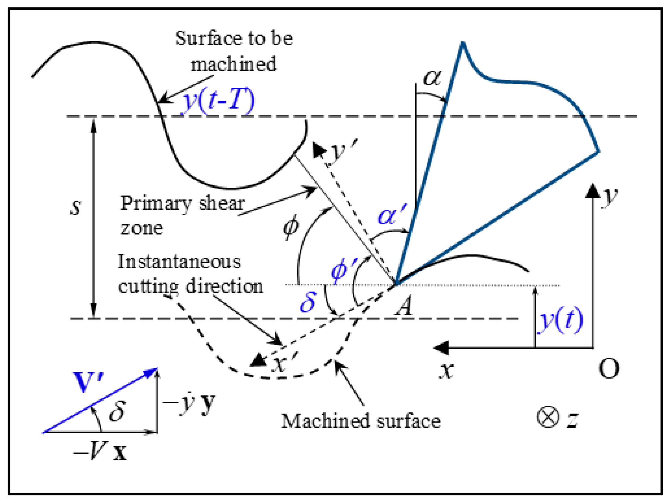
  • The model takes into account the fact that the regenerative effect results in a variation over time of the cutting conditions (cutting speed, uncut chip thickness, tool rake angle) and the tribological behavior at the tool–chip interface.
  • A new computational strategy reducing the computational times in the non-linear approach was developed.
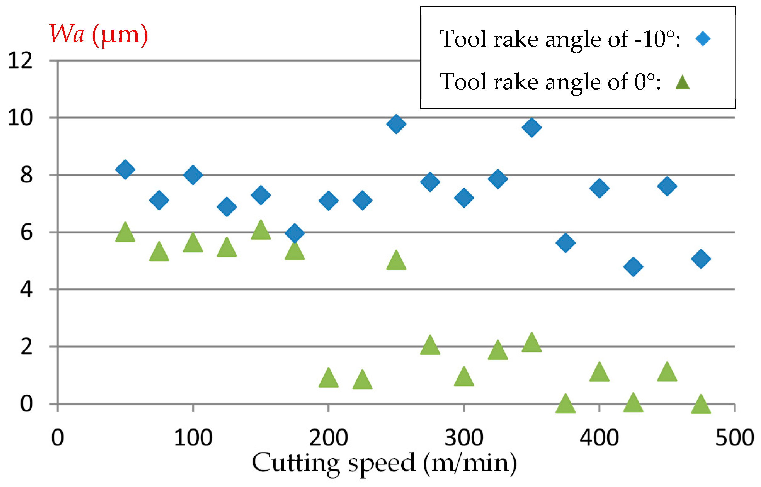
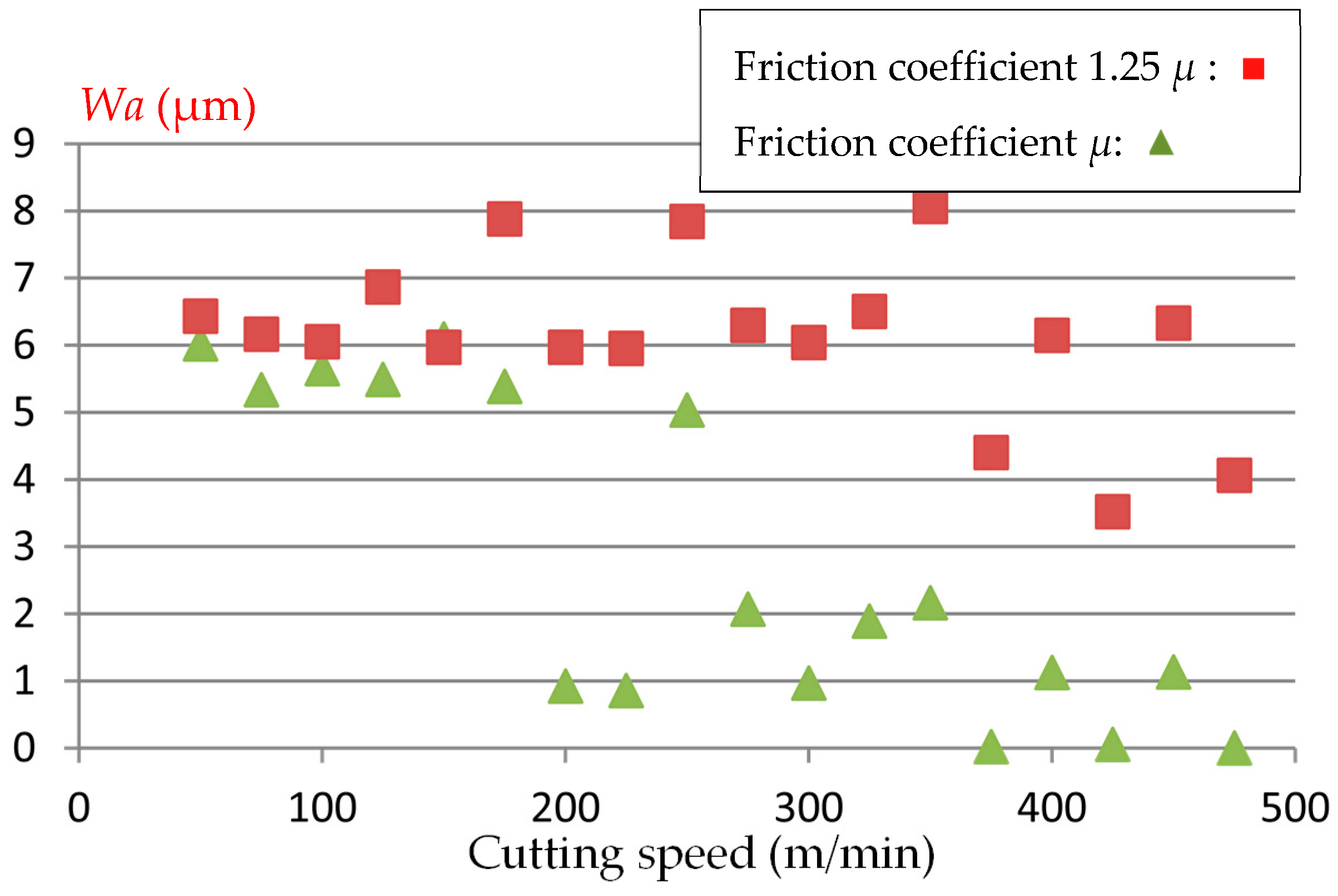
  • The arithmetic mean deviation of the waviness profile Wa is highly non-linear with respect to the cutting conditions.
  • The friction conditions at the tool–chip interface significantly affect the parameter Wa.

Author Contributions

E.M.K. evaluated the modeling and simulation. A.M., S.D., and I.M. analyzed the results. All authors participated in the discussion and elaboration of the manuscript.

Funding

This research received no external funding.

Conflicts of Interest

The authors declare no conflicts of interest.

References

  1. Rakit, A.K.; Osman, M.O.M.; Sankar, T.S. Machine tool vibrations: Its effect on manufactured surface. In Proceedings of the 4th Canadian Congress of Applied Mechanics, Montreal, QC, Canada, 28 May–1 June 1973; pp. 463–464. [Google Scholar]
  2. Lasota, A.; Rusek, P. Influence of random vibrations on the roughness of turned surfaces. J. Mech. Work. Technol. 1983, 7, 277–284. [Google Scholar] [CrossRef]
  3. Sata, T.; Li, M.; Takata, S.; Hiraoka, H.; Xing, X.; Xiao, X. Analysis of surface roughness generation in turning operation and its application. Ann. CIRP 1985, 34, 473–476. [Google Scholar] [CrossRef]
  4. Mital, A.; Mehta, M. Surface finish prediction models for the fine turning. Int. J. Prod. Res. 1988, 26, 1861–1876. [Google Scholar] [CrossRef]
  5. Zhang, G.M.; KapoorDynamic, S.G. Generation of machined surfaces, Parts 1 and 2. ASME J. Eng. Ind. 1991, 113, 137–152. [Google Scholar] [CrossRef]
  6. Mer, B.; Diniz, A.E. Correlating tool wear, tool life, surface-roughness and tool vibration in finish turning with coated carbide tools. Wear 1994, 173, 137–144. [Google Scholar]
  7. Jang, D.Y.; Choi, Y.G.; Kim, H.G.; Hsiao, A. Study of the correlation between surface roughness and cutting vibrations to develop an online roughness measuring technique in hard turning. Int. J. Mach. Tools Manuf. 1996, 36, 453–464. [Google Scholar] [CrossRef]
  8. Abouelatta, O.B.; Madl, J. Surface roughness prediction based on cutting parameters and tool vibrations in turning operations. J. Mater. Process. Technol. 2001, 118, 269–277. [Google Scholar] [CrossRef]
  9. Hessainia, Z.; Belbah, A.; Athmane Yallese, M.; Mabrouki, T.; Rigal, J.F. On the prediction of surface roughness in the hard turning based on cutting parameters and tool vibrations. Measurement 2013, 46, 1671–1681. [Google Scholar] [CrossRef]
  10. Rao, K.V.; Murthy, B.S.N.; Rao, N.M. Cutting tool condition monitoring by analyzing surface roughness, work piece vibration and volume of metal removed for AISI 1040 steel in boring. Measurement 2013, 46, 4075–4084. [Google Scholar]
  11. Ancio, F.; Gámez, A.J.; Marcos, M. Factors influencing the generation of a machined surface. Application to turned pieces. J. Mater. Process. Technol. 2015, 215, 50–61. [Google Scholar] [CrossRef]
  12. López de Lacalle, L.N.; Lamikiz, A.; Sanchez, J.A.; Salgado, M.A. Effects of tool deflection in the high-speed milling of inclined surface. Int. J. Adv. Manuf. Technol. 2004, 24, 621–631. [Google Scholar] [CrossRef]
  13. Wojciechowski, S.; Maruda, R.W.; Krolczyk, G.M.; Niesłony, P. Application of signal to noise ratio and grey relational analysis to minimize forces and vibrations during precise ball end milling. Precis. Eng. 2018, 51, 582–596. [Google Scholar] [CrossRef]
  14. Tobias, S.A.; Fishwick, W. The chatter of lathe tools under orthogonal cutting conditions. Trans. ASME 1958, 80, 1079–1088. [Google Scholar]
  15. Tlusty, J.; Polacek, M. The stability of the machine tool against self-exited vibration in machining. Int. Res. Prod. Eng. ASME 1963, 1, 465–474. [Google Scholar]
  16. Meritt, H.E. Theory of self-excited machine tool chatter contribution to machine-tool chatter: Contribution to machine-tool chatter, research 1. ASME J. Eng. Ind. 1965, 64, 447–454. [Google Scholar] [CrossRef]
  17. Tobias, S.A. Machine-Tool Vibration; Blackie & Son: London, UK, 1965. [Google Scholar]
  18. Minis, I.E.; Magrab, E.B.; Pandelidis, I.O. Improved methods for prediction of chatter in turning, Part 1: Determination of structural response parameters. Trans. ASME J. Eng. Ind. 1990, 112, 12–35. [Google Scholar] [CrossRef]
  19. Shawky, A.M.; Elbestawi, M.A. An enhanced dynamic model in turning including the effect of ploughing forces. Trans. ASME J. Manuf. Sci. Eng. 1997, 119, 10–20. [Google Scholar] [CrossRef]
  20. Altintas, Y. Manufacturing Automation: Metal Cutting Mechanics, Machine Tool Vibrations and CNC Design; Cambridge University Press: Cambridge, UK, 2000. [Google Scholar]
  21. Lazoglu, I.; Atabey, F.; Altintas, Y. Dynamics of boring processes: Part III-time domain modeling. Int. J. Mach. Tools Manuf. 2002, 42, 1567–1576. [Google Scholar] [CrossRef]
  22. Kilic, Z.M.; Altintas, Y. Generalized mechanics and dynamics of metal cutting operations for unified simulations. Int. J. Mach. Tools Manuf. 2016, 104, 1–13. [Google Scholar] [CrossRef]
  23. Wu, D.W.; Liu, C.R. An analytical model of cutting dynamics. Part1: Model building. Trans. ASME J. Eng. Ind. 1985, 107, 107–111. [Google Scholar] [CrossRef]
  24. Tarng, Y.S.; Young, H.T.; Lee, B.Y. An analytical model of chatter vibration in metal cutting. Int. J. Mach. Tools Manuf. 1994, 34, 183–197. [Google Scholar] [CrossRef]
  25. Peigne, G.; Paris, H.; Brissaud, D.; Gouskov, A. Impact of the cutting dynamics of small radial immersion milling operations on machined surface roughness. Int. J. Mach. Tools Manuf. 2004, 44, 1133–1142. [Google Scholar] [CrossRef]
  26. Schmitz, T.L.; Couey, J.; Marsh, E.; Mauntler, N.; Hughes, D. Runout effects in milling: Surface finish, surface location error, and stability. Int. J. Mach. Tools Manuf. 2007, 47, 841–851. [Google Scholar] [CrossRef]
  27. Afazov, S.M.; Ratchev, S.M.; Segal, J.; Popov, A.A. Chatter modelling in micro-milling by considering process nonlinearities. Int. J. Mach. Tools Manuf. 2012, 56, 28–38. [Google Scholar] [CrossRef] [Green Version]
  28. Shi, Z.; Liu, L.; Liu, Z. Influence of dynamic effects on surface roughness for face milling process. Int. J. Adv. Manuf. Technol. 2015, 80, 1823–1831. [Google Scholar]
  29. Wojciechowski, S.; Twardowski, P.; Pelic, M.; Maruda, R.W.; Barrans, S.; Krolczyk, G.M. Precision surface characterization for finish cylindrical milling with dynamic tool displacements model. Precis. Eng. 2016, 46, 158–165. [Google Scholar] [CrossRef]
  30. Wojciechowski, S.; Mrozek, K. Mechanical and technological aspects of micro ball end milling with various tool inclinations. Int. J. Mech. Sci. 2017, 134, 424–435. [Google Scholar] [CrossRef]
  31. Wojciechowski, S.; Wiackiewicz, M.; Krolczyk, G.M. Study on metrological relations between instant tool displacements and surface roughness during precise ball end milling. Measurement 2018, 129, 686–694. [Google Scholar] [CrossRef]
  32. Wiercigroch, M.; Budak, E. Sources of nonlinearities, chatter generation and suppression in metal cutting. Philos. Trans. R. Soc. Lond. A 2001, 359, 663–693. [Google Scholar] [CrossRef] [Green Version]
  33. Karube, S.; Hoshino, W.; Soutome, T.; Sato, K. The non-linear phenomena in vibration cutting system. The establishment of dynamic model. Int. J. Non-Linear Mech. 2002, 37, 541–564. [Google Scholar] [CrossRef]
  34. Moufki, A.; Devillez, A.; Segreti, M.; Dudzinski, D. A semi-analytical model of non-linear vibrations in orthogonal cutting and experimental validation. Int. J. Mach. Tools Manuf. 2006, 46, 436–449. [Google Scholar] [CrossRef]
  35. Fu, Z.; Zhang, X.; Wang, X.; Yang, W. Analytical modeling of chatter vibration in orthogonal cutting using a predictive force model. Int. J. Mech. Sci. 2014, 88, 145–153. [Google Scholar] [CrossRef]
  36. Moufki, A.; Dudzinski, D.; Le Coz, G. Prediction of cutting forces from an analytical model of oblique cutting, application to peripheral milling of Ti-6Al-4V alloy. Int. J. Adv. Manuf. Technol. 2015, 81, 615–626. [Google Scholar] [CrossRef]
  37. Huo, M.; Zhao, J.; Xie, H.; Li, Z.; Li, S.; Zhang, H.; Jiang, Z. Analysis of surface roughness alteration in micro flexible rolling. Wear 2019, 426–427, 1286–1295. [Google Scholar] [CrossRef]
  38. Nguyen, T.T. Prediction and optimization of machining energy, surface roughness, and production rate in SKD61 milling. Measurement 2019, 136, 525–544. [Google Scholar] [CrossRef]
Figure 1. Tool–workpiece interaction during the dynamic cutting process, which was assimilated to a single degree of freedom in the feed direction (y-direction). The stationary cutting parameters (i.e., without vibrations) α , V , s , and ϕ represent the tool rake angle, the cutting speed, the uncut thickness, and the shear angle, respectively. y ( t ) is the tool displacement during the tool vibrations.
Jmmp 03 00053 g001
Figure 2. At each time t, an equivalent cutting steady-state operation is introduced. The associated instantaneous cutting conditions V , α , and s represent the cutting speed, the tool rake angle, and the uncut chip thickness, respectively.
Jmmp 03 00053 g002
Figure 3. Simulated surface profile: effect of cutting speed (uncut chip thickness = 0.01 mm; tool rake angle = 0°; width of cut = 1.5 mm).
Jmmp 03 00053 g003
Figure 4. Effect of the tool rake angle on the arithmetic mean deviation of the waviness profile Wa (uncut chip thickness = 0.01 mm; width of cut = 1.5 mm; cutting speed = 50 to 500 m/min).
Jmmp 03 00053 g004
Figure 5. Effect of the friction coefficient µ on the arithmetic mean deviation of the waviness profile Wa (uncut chip thickness = 0.01 mm; tool rake angle = 0°; width of cut = 1.5 mm; cutting speed = 50 to 500 m/min).
Jmmp 03 00053 g005
Table 1. Chemical composition of the medium carbon steel 42CrMo4 (AISI 4142).
ElementsCSiMnSPNiCrMoCuAl
× 10−3 (wt.%)4652249421715171107026524522
Table 2. Thermo-mechanical properties of the medium carbon steel 42CrMo4 (AISI 4142).
Hardness (Brinell)Yield Stress (MPa)Ultimate Tensile Strength (MPa)Heat Capacity
(J∙Kg−1∙K)
Thermal Conductivity
(W∙m−1∙K)
24148581450036

