Development of Small UAS Beyond-Visual-Line-of-Sight (BVLOS) Flight Operations: System Requirements and Procedures


1
Faculty of Engineering and Applied Science, Memorial University, St. John’s, NL A1B 3X5, Canada
2
School of Engineering and Computing, University of West Scotland, Paisley, Scotland PA1 2BE, UK
*
Author to whom correspondence should be addressed.
Drones 2018, 2(2), 13; https://doi.org/10.3390/drones2020013
Submission received: 5 February 2018
/
Revised: 29 March 2018
/
Accepted: 4 April 2018
/
Published: 9 April 2018
Abstract
:Due to safety concerns of integrating small unmanned aircraft systems (UAS) into non-segregated airspace, aviation authorities have required a set of detect and avoid (DAA) systems to be equipped on small UAS for beyond-visual-line-of-sight (BVLOS) flight operations in civil airspace. However, the development of small UAS DAA systems also requires BVLOS flights for testing and validation. To mitigate operational risks for small UAS BVLOS flight operations, this paper proposes to initially test small UAS DAA systems in BVLOS flights in a restricted airspace with additional safety features. Later, this paper further discusses the operating procedures and emergency action plans for small UAS BVLOS flight operations. The testing results show that these safety systems developed can help improve operational safety for small UAS BVLOS flight operations.
1. Introduction
Nowadays, Unmanned Aircraft Systems (UAS) have become more and more popular for both civilian and commercial applications. They have been used for environmental monitoring and measurements, emergency response, homeland security, precision agriculture, land management, infrastructure monitoring, and commercial applications such as aerial photography and transportation of goods and post [1,2]. However, as no human pilots are on Unmanned Aircraft (UA), they generally lack the critical ability to Detect and Avoid (DAA) other aircraft during their flight operations [3]. In addition, the other significant issue for operating UAS is the fact that the UA pilots control the UA in a remote manner, typically relying on radio frequency (RF) and/or satellite communication to establish a Command and Control (C2) link between the Ground Control Station (GCS) and the UA. For safe operations of UAS, the C2 link has to be robustly, reliably, and redundantly established. When the C2 link does fail, the UA should perform predictable and acceptable “lost link” procedures similar to manned aircraft autopilot systems [4].
For these safety concerns, civil aviation authorities like the Federal Aviation Administration (FAA) in the US and Transport Canada in Canada have not allowed UAS to be integrated into non-segregated airspace (airspace shared with manned aviation) [5,6]. Currently, they only allow UAS to operate within Visual Line of Sight (VLOS) in limited areas under Certificates of Waiver or Authorization (COA) in the US and Special Flight Operations Certificates (SFOC) in Canada [7,8]. As to commercial demands of UAS Beyond Visual Line of Sight (BVLOS) operations in civil airspace, both FAA and Transport Canada have required UAS to be equipped with DAA systems to prevent potential loss of separation or mid-air collisions from oncoming traffic during flight operations. Large UAS can have the same DAA systems installed as manned General Aviation (GA) aircraft, such as airborne radar, the Traffic Collision Avoidance System (TCAS), and the Automatic Dependent Surveillance-Broadcast (ADS-B), to achieve a level of safety equivalent to manned GA aircraft [4,9]. However, due to limitations of Size, Weight, and Power (SWaP), small UAS require newly-developed small, light, and low-power versions of airborne sensors or ground-based sensors for safe operations in civil airspace. To reflect this reality, a small UAS DAA system based on light-weight airborne ADS-B and ground portable radar systems is proposed by the RAVEN project (the RAVEN project is based at Memorial University, St. John’s, NL, Canada, and their main research objective is to develop intelligent DAA systems to allow small UAS to share the same airspace with manned aviation) to assist small UAS in achieving the equivalent level of safety as manned GA aircraft. This is important for the future integration of small UAS into civil airspace.
2. Background
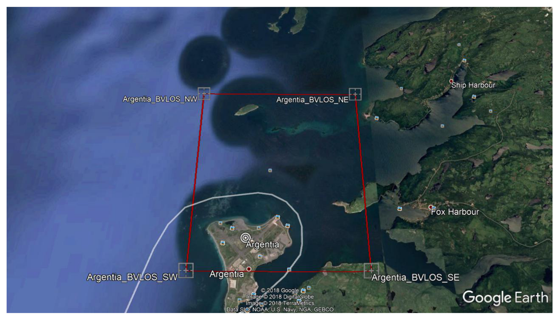
In the DAA research, the ability to test small UAS DAA systems in BVLOS flights for normal air traffic scenarios is critical to the success of system development, performance testing, and system validation. As an intermediate solution to mitigate the operational safety risks for small UAS DAA system tests, the RAVEN project applied for a new SFOC for BVLOS flight operations in a restricted airspace at the RAVEN test site in Argentia, NL, Canada [10]. During a BVLOS flight, UA often fly out of the visual range of the Pilot-in-Command (PIC); thus, extra safety features have to be installed on the UA to prevent the aircraft from flying beyond the restricted area assigned by the SFOC. Depending on the safety features installed onboard the UA and at the associated GCS, Transport Canada evaluates whether the applicant’s proposed operations are safe enough to warrant issuing a BVLOS SFOC. In the RAVEN BVLOS SFOC application, with the previous operating experience learned from Aerosonde UAS (the RAVEN project had carried out a number of environment monitoring BVLOS missions with Aerosonde UAS at the Clarenville—Random Island area, in Clarenville, NL, Canada back to 2007 as described in Appendix A), extended communication links, a First Person View (FPV) video system, a flight termination system (FTS), and Geo-fence and Return-To-Launch (RTL) functions enabled in the autopilot are added to prove to Transport Canada that the RAVEN project has the capability to prevent RAVEN UA from flying away during a BVLOS flight. After these safety measures were designed, implemented, and demonstrated in flight tests, the RAVEN project was granted an SFOC for BVLOS flight operations at the RAVEN Argentia test site from Transport Canada, represented by the red box (6 km by 8 km) on the map in Figure 1, and has carried out a series of testing missions for the development of the RAVEN-proposed small UAS DAA system.
3. System Requirements for BVLOS Flight Operations
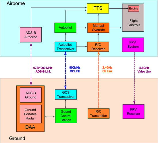
As shown in Figure 2, additional FTS and FPV systems are installed on the UA and integrated with its built-in autopilot and R/C control systems. Four RF links are used during BVLOS flight operations: a 900 MHz C2 link is used for the communication between the autopilot and the GCS; a 2.4 GHz C2 link is used for R/C manual control; a 5.8 GHz video link is used for real-time airborne video transmission, and a 978/1090 MHz ADS-B link is used for cooperative air traffic detection. During normal operations, the FTS checks the healthy status of the 900 MHz and 2.4 GHz links. If both links are lost for more than two minutes, the FTS will terminate the engine to prevent the UA from flying away. At ranges beyond the visual range of the manual pilot (approximately 500 m) and within the R/C link range (approximately 2000 m), the FPV video system can help the manual pilot control the aircraft to fly home (using manual R/C control) if the autopilot system fails. At ranges beyond the R/C link range, the FPV system allows ground control station operators to visually monitor the progress of the flight and the status of the onboard systems.
3.1. Extended Communication Links
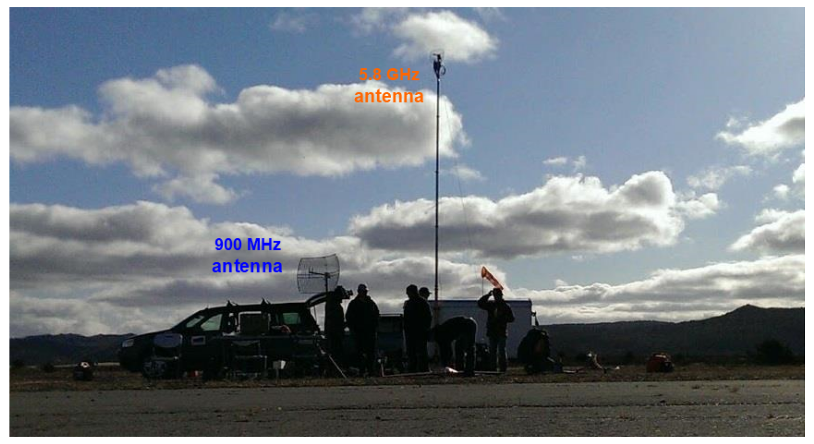
For VLOS flight operations,“rubber ducky” type omni-directional antennas are typically used for all RF communications. The operational range of these antennas is approximately 3 km for the 900 MHz C2 link and only 500 m for the 5.8 GHz video link which is insufficient for BVLOS flight operations. As shown in Figure 3, two high-gain directional grid-dish antennas described in Table 1 are used to extend the RF communication range.
Ground range tests are performed between the ground devices and the airborne avionics. The GCS, the FPV receiver and two high-gain antennas are sited on the runway, and the autopilot, the FPV camera, and the FPV transmitter are installed on the top of a hill located 2.5 km east of the runway and 100 m higher in elevation. The results show that 20 dB of attenuation can be applied to the 900 MHz C2 link and 10 dB of attenuation can be added to the 5.8 GHz video link before both links are lost. In other words, the 900 MHz C2 link has an operating range of approximately 25 km and the 5.8 GHz video link has a range of approximately 7.5 km. Therefore, both antennas are suitable for the 7 km BVLOS flights displayed in Figure 1.
3.2. Flight Termination System
A safety requirement for the RAVEN BVLOS flight operations is for all UAS to be equipped with a flight termination system (FTS) that prevents the aircraft from flying beyond the restricted airspace assigned by the SFOC [11]. To fulfill this requirement, an FTS (Figure 4) is developed that terminates the aircraft engine to prevent from flying away when both the R/C and autopilot C2 links are lost for more than two minutes. With a redundant design, the FTS can also be manually triggered by an R/C toggle switch on the R/C console over the 2.4 GHz C2 link.
In the R/C receiver and the autopilot, the status of the communication links can be configured and shown as servo PWM output signals. For example, when the communication links are reliable and robust the PWM pulse width is 1 ms, and when communication is lost the pulse width increases to 2 ms. In order to detect these signals, a hardware PWM signal decoder (as shown in Figure 4) is used to convert the PWM pulse width into an analog voltage which can be measured by an analog to digital converter (ADC) in a microcontroller. The microcontroller then compares all the inputs, starts a timer if both links are lost, and sends out the engine termination command when the timer is timed out.
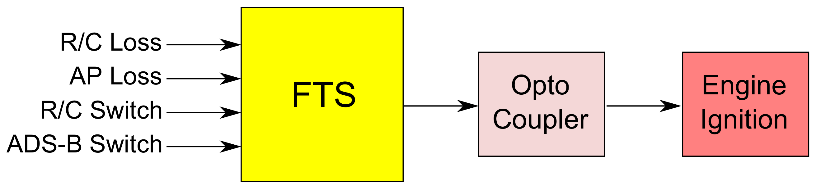
As depicted in Figure 5, this FTS has four PWM inputs (i.e., R/C C2 link loss, autopilot C2 link loss, R/C termination switch, and ADS-B termination switch) and one PWM output (engine termination command). When PWM input values are low (i.e., less than 1200 or 1.2 ms), they are not engaged; when they are high (i.e., greater than 1800 or 1.8 ms), they are engaged. On the other hand, when PWM output values are low, the engine keeps running; when they are high, the engine is to be terminated.
3.3. First Person View (FPV) System
The RAVEN FPV system is used as an additional safety feature in BVLOS flight operations and is mandated by the RAVEN SFOC for use/installation on UA involved in BVLOS operations [12]. The FPV system provides situational awareness to the Pilot-in-Command (PIC) and increases the pilot’s ability to recover the UA from unexpected behaviour, or allows the PIC to control the UA to avoid potential risks. In addition to the FPV video, the system provides important telemetry data to the PIC and other ground operators including location, altitude, speed, attitude, heading, direction to home, power consumption, and other user selectable parameters.
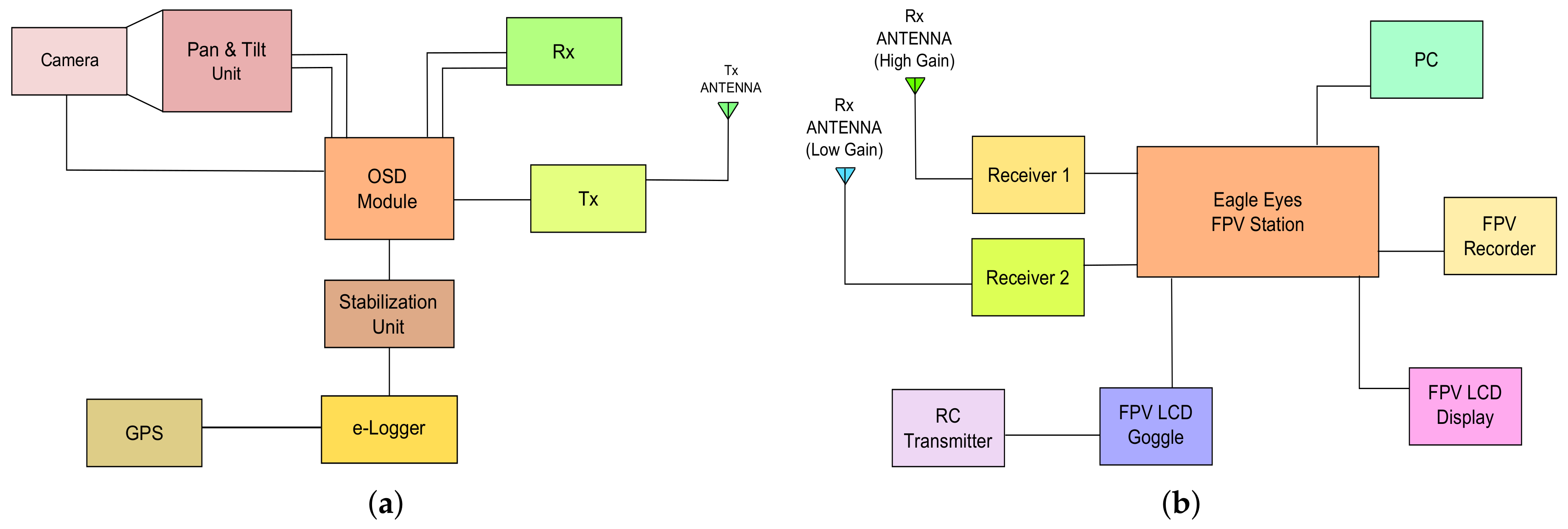
The FPV system uses an independent set of sensors for telemetry and does not depend on any sensors used by the autopilot. In Figure 6a, the FPV camera has pan and tilt capabilities when operated within the R/C C2 link range (about 2 km). To increase the reliability of the FPV system’s reception, the video receiver in Figure 6b has two antennas installed, i.e., a low-gain omnidirectional antenna is used to receive signals when UA are close to the GCS and a high-gain directional antenna is used when UA are further from the GCS.
3.4. Geo-Fence and Return-to-Launch (RTL) Functions
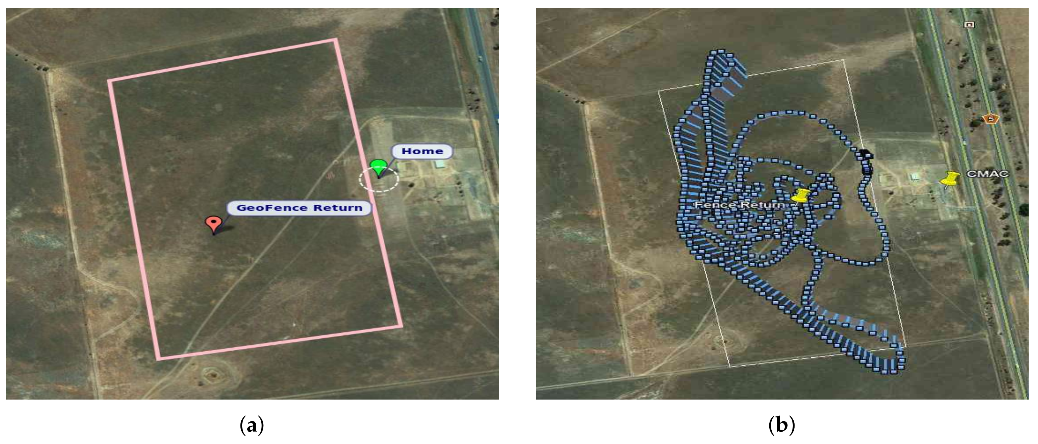
Geo-fence and RTL functions should be set and enabled in the UA autopilot system. As shown in Figure 7a, the Geo-fence defines a box area on the map via several GPS waypoints around the planned flying area, plus a minimum and maximum altitude, between which the UA can fly [13]. Within the fence, the UA can fly normally. If the UA flies outside the fenced area, the autopilot will automatically take over and bring the aircraft back to a pre-defined safe waypoint inside the fenced area.
The RTL function can command the UA to fly back to the launch location regardless of the existing flight plan in the autopilot. It is engaged when the autopilot loses communication with its GCS for more than 10 s. In the BVLOS operation, if the UA flies too far and loses the communication link with the GCS, the autopilot will command the UA to fly back, so that the communication link can be established again within two minutes before the FTS terminates the engine.
3.5. RAVEN-Proposed Small UAS DAA System
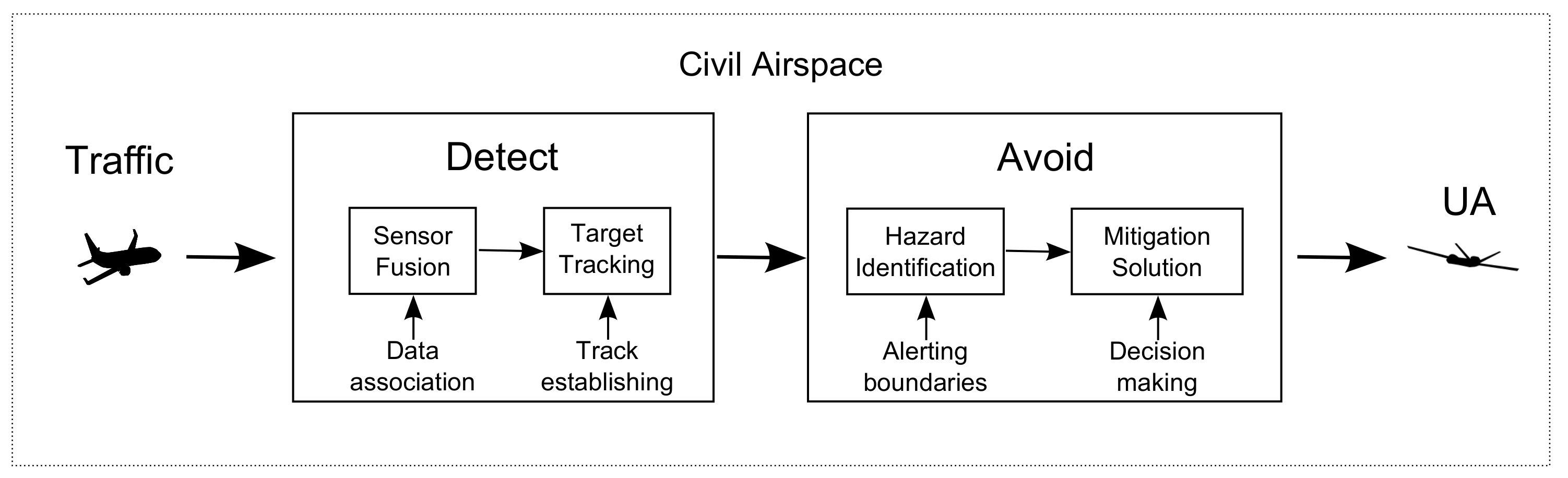
For safe UAS operations, aviation authorities have required the installation of DAA systems for UAS to maintain “well clear” with other air traffic during BVLOS flight operations [3,4]. For this requirement and SWaP limitations on small UAS, the RAVEN project has proposed a small UAS DAA system as shown in Figure 8, where ADS-B and ground portable radar systems are integrated together to detect cooperative and non-cooperative traffic near UAS operating areas, and then those tracked intruders are fed into the Avoid module to identify hazards and carry out collision mitigation for small UAS to avoid Near Mid-Air Collisions (NMACs) during BVLOS flight operations.
3.5.1. ADS-B for Cooperative Traffic
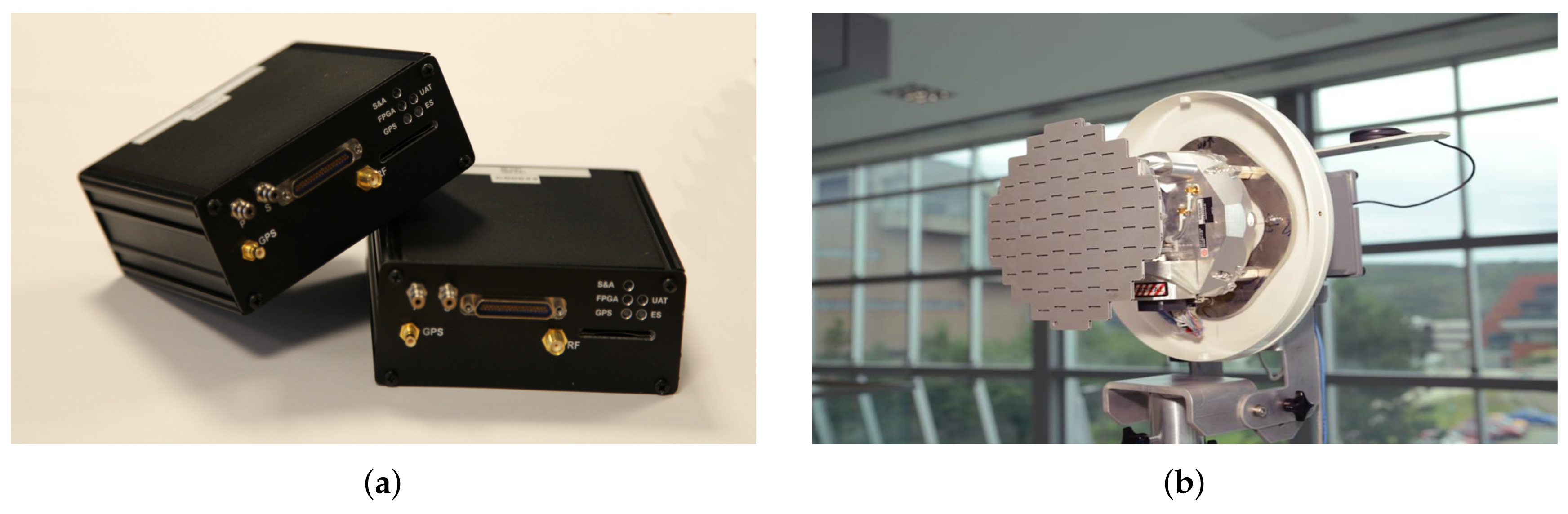
Since 2011, the RAVEN project has partnered with R-Cubed Engineering for the use of their All-Weather Sense and Avoid System (AWSAS) shown in Figure 9a. AWSAS is an ADS-B technology-based system which transmits ADS-B positional information on 978 MHz and receives ADS-B radio transmissions on both 978 MHz ES and 1090 MHz [14,15].
3.5.2. Ground Portable Radar for Non-Cooperative Traffic
Since 2014, the RAVEN project has also worked with Seamatica Aerospace (SMA) for the use of their Zeus ground portable radar. As shown in Figure 9b, the Zeus radar is based on OEM hardware originally designed for airborne weather detection. It operates at X-band (permitting physically small and light-weight RF hardware to be employed) and makes exclusive use of solid state technology. In addition, the Zeus radar uses long pulses with linear frequency modulation (LFM) pulse compression to increase the energy on target while maintaining a tight range resolution [16].
3.5.3. Determine Alerting Boundaries for Hazard Identification
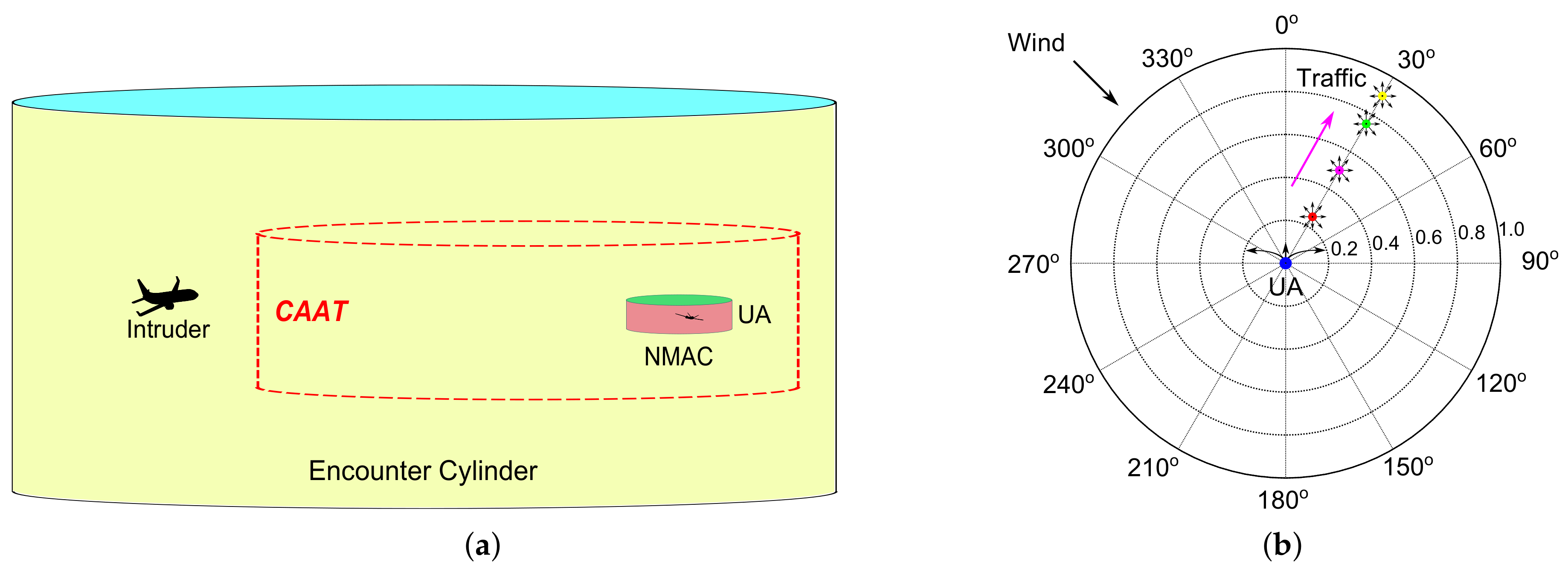
As introduced in [3], the NMAC boundary is a standard cylinder around the UA: 500 ft in radius horizontally, and ±100 ft in height vertically. Moreover, in Figure 10a, the Collision Avoidance Alerting Threshold (CAAT) boundary is defined as the closest range boundary at which the UA can still avoid NMAC with the traffic by a horizontal maneuver within the Flight Performance Envelope (FPE), i.e., an outer layer outside of the NMAC cylinder. Since small UAS are sensitive to ever-changing flight environments such as encounter geometries, relative velocities, and wind conditions (i.e., wind speed and wind direction), small UAS CAAT boundaries cannot be directly calculated through mathematical equations. These are usually estimated based on simulation methods via millions of simulated mid-air encounters, e.g., a Monte Carlo (MC) simulation method designed and developed in [18].
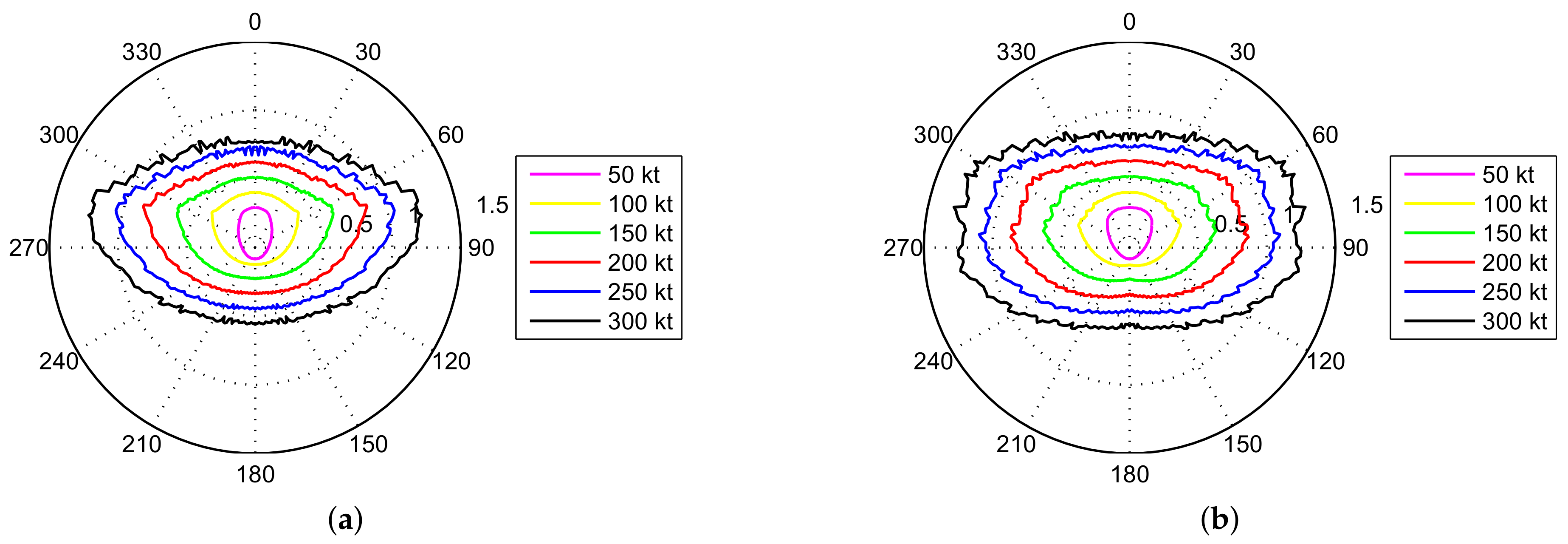
For simplicity, the vertical CAAT boundary is pre-defined at fixed heights ±450 ft. Thus, only the horizontal CAAT boundary needs to be determined via simulation methods by a series of co-altitude mid-air encounters [18]. As described in Figure 10b, a web structure is adopted in MC simulations to locate CAAT boundaries in various wind conditions, where traffic aircraft are initiated from inner circles to outer circles at bearing angles [0°, 360°) with heading angles in [0°, 360°); UA are initiated at the web center with the 0° heading angle (to the north). At each bearing angle, we locate the shortest horizontal range between UA and traffic, at which UA can avoid NMACs with traffic in all possible headings by one of the appropriate horizontal maneuvers. Through MC simulations, a set of sample summarized CAAT boundaries are acquired and drawn in Figure 10b with their maximum range at each bearing angle to cover encounters in various wind conditions [18]. In general, the UA front CAAT boundaries in Figure 10b are enlarged in comparison with the ones without wind in Figure 10a. Furthermore, Figure 11a,b show that UA require longer horizontal ranges to avoid NMACs for traffic from the side regions of UA, such as at the bearing angles [60°, 120°] and [240°, 300°], because during UAS operations they are the most vulnerable bearing regions on CAAT boundaries in various wind conditions [18].
3.5.4. Evasive Maneuvering Algorithm for Collision Mitigation Solutions
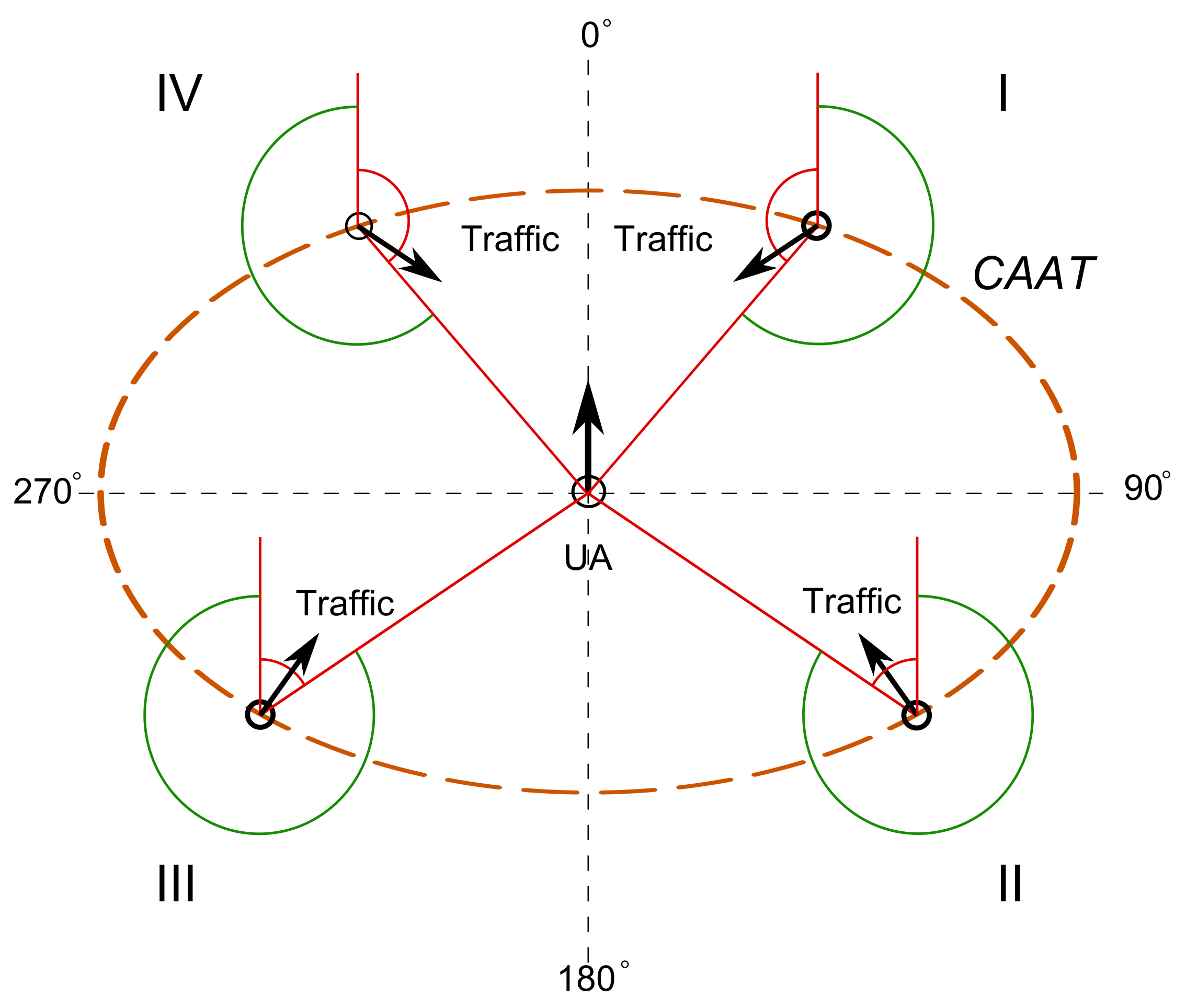
In Figure 12, once NMACs are projected and the break-ins are predicted on the CAAT boundary in the next five seconds, the evasive maneuvering algorithm evaluates collision risks and triggers horizontal maneuvers, based on the traffic-detected relative bearing () and the traffic relative heading () with respect to the UA in four quadrants from 0° to 360°. In each quadrant in Figure 12, when traffic is heading to the red regions (displayed as the red arc areas), the algorithm starts to initiate evasive maneuvers to steer the UA to the safe regions which are far away from traffic. The UA will then remain there until the horizontal range rate and the horizontal range 2 nmi between the UA and traffic. Assume that maximum 2 g turns (turn rate at 6°/s) can be achieved on the UA. The UA horizontal maneuvering options at four quadrants in Figure 12 are designed differently and their details are described as follows:
(1) Horizontal maneuvers in quadrant I:
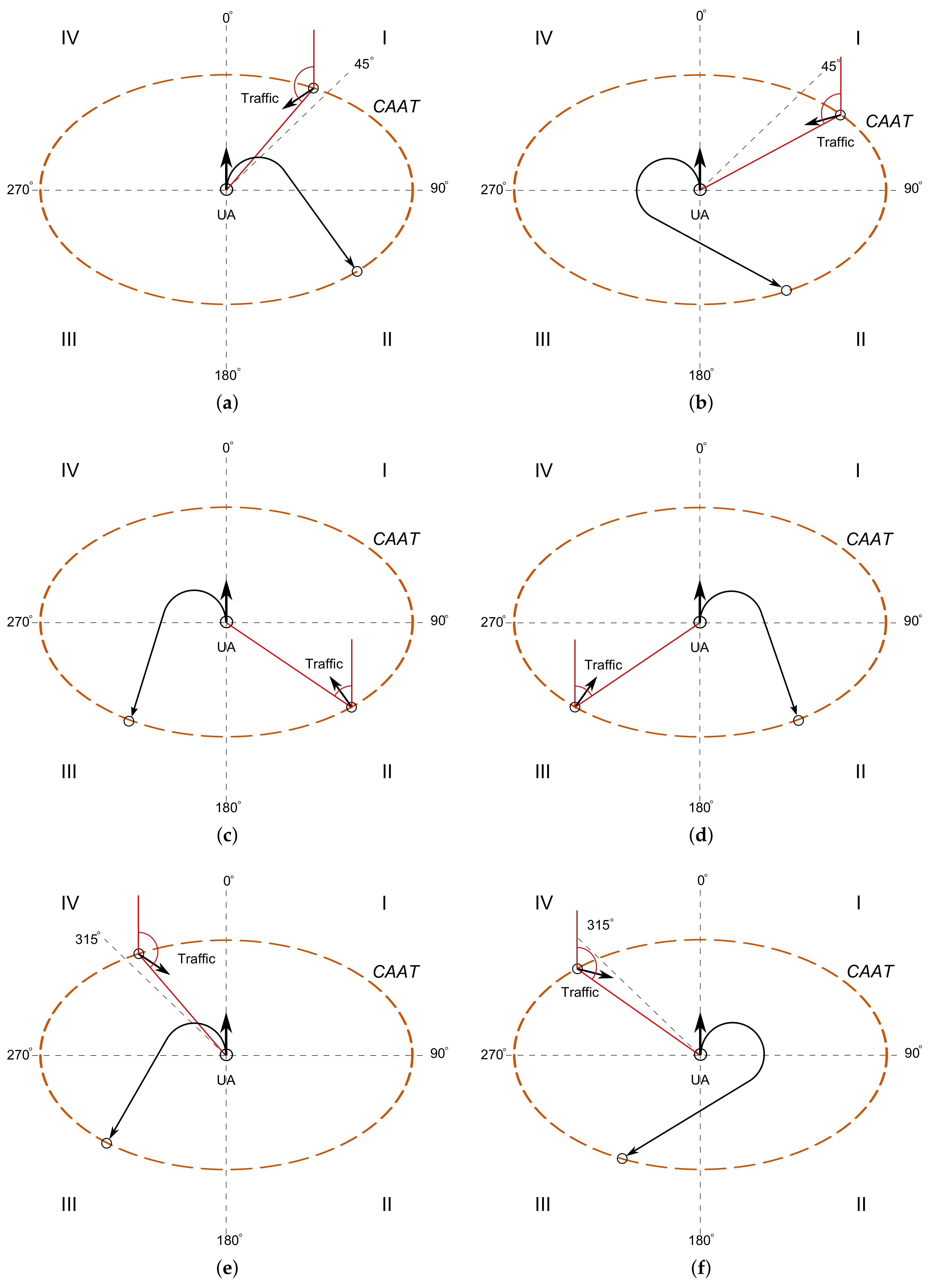
As shown in Figure 13a,b, the maneuvering strategy in quadrant I is to let the UA fly to safe waypoints in quadrant II, which are located at a position 90° off the traffic break-in bearings on the WC boundary in quadrant II. Upon the traffic break-in bearings, the UA make left turns or right turns to fly to the predefined safe waypoints. The UA make right turns when the break-in bearing is less than 45°; and the UA make left turns when the break-in bearing is greater than 45°.
(2) Horizontal maneuvers in quadrant II and III
In Figure 13c,d, two maneuvering strategies are described for the cases when traffic are coming from the rear of the UA. In Figure 13c, the UA make left turns to fly to the predefined safe waypoints in quadrant III when the traffic break-in bearing is in quadrant II (rear right of the UA). In Figure 13d, the UA make right turns to fly to the predefined safe waypoints in quadrant II when the traffic break-in bearing is in quadrant III (rear left of the UA).
(3) Horizontal maneuvers in quadrant IV
In Figure 13e,f, the UA make left turns to fly to the predefined safe waypoints in quadrant III when the break-in bearing is greater than 315°; and the UA make right turns to fly to the predefined safe waypoints in quadrant III when the break-in bearing is less than 315°.
(4) Vertical maneuvering strategy in the three-dimensional evasive maneuvering algorithm
In collision mitigation, horizontal and vertical maneuvers are typically engaged at the same time to help small UAS escape from emergencies as soon as possible. The vertical maneuvering strategy is designed based on the vertical separation and the traffic vertical rate ; namely, it is to increase the vertical separation between the UA and traffic, so that the vertical separation at the horizontal Closest Point of Approach (CPA) can be greater than 100 ft ( ft). This strategy is described in further detail with the corresponding diagrams for different encounter geometries in Table 2.
4. Procedures for BVLOS Flight Operations
Two sets of operating procedures are discussed in this section: the standard operation procedure (SOP) and the emergency procedure for link-loss failure action plans.
4.1. Standard Operating Procedure
During RAVEN BVLOS flights, the SOP is used as follow:
- Install payload on the UA and fuel/charge the aircraft.
- Switch off Geo-fence from the switch on the R/C console.
- Setup FPV ground station and check for proper operation.
- Pilot-in-Command (PIC) perform the pre-flight checklist.
- PIC set Geo-fence maximum altitude to 500 m and minimum altitude to 100 m (depending on the SFOC).
- PIC set the flight plan at GCS and upload to UA.
- Manual R/C pilot take off and fly to safe altitude over 100 m and enable Geo-fence from the switch on the R/C console.
- Check for proper operation of FPV system.
- Set UA to auto mode to carry on the flight plan.
- Backup/FPV pilot observe the real-time FPV video and telemetry data during flight and manual R/C pilot observe FPV screen when UA is cruising beyond visual range.
- PIC check UA status at GCS and monitor BVLOS mission.
- Once the mission is done and UA is back on the runway, manual R/C pilot switch off Geo-fence from the toggle switch on the R/C console, take manual control and land UA.
4.2. Emergency Procedure for Link-Loss Failure Action Plans
During BVLOS flights, link-loss failures are the main factors that might lead a UA to fly away. Table 3 describes how R/C, Autopilot (AP), and FPV link-loss failures are handled during BVLOS flights. Note that heartbeat messages are transmitted and received at a pre-defined update rate on both sides of communication links, thus the communication link failure can be determined when heartbeat messages have not been received on one side of communication links in a certain period of time (e.g., 2 s). In this case, a PWM channel of the R/C receiver on the UA can be configured as link status to indicate the autopilot when a R/C link-loss occurs.
4.3. Procedure Training and System Tests on Hardware-in-Loop (HIL) Testing Platform
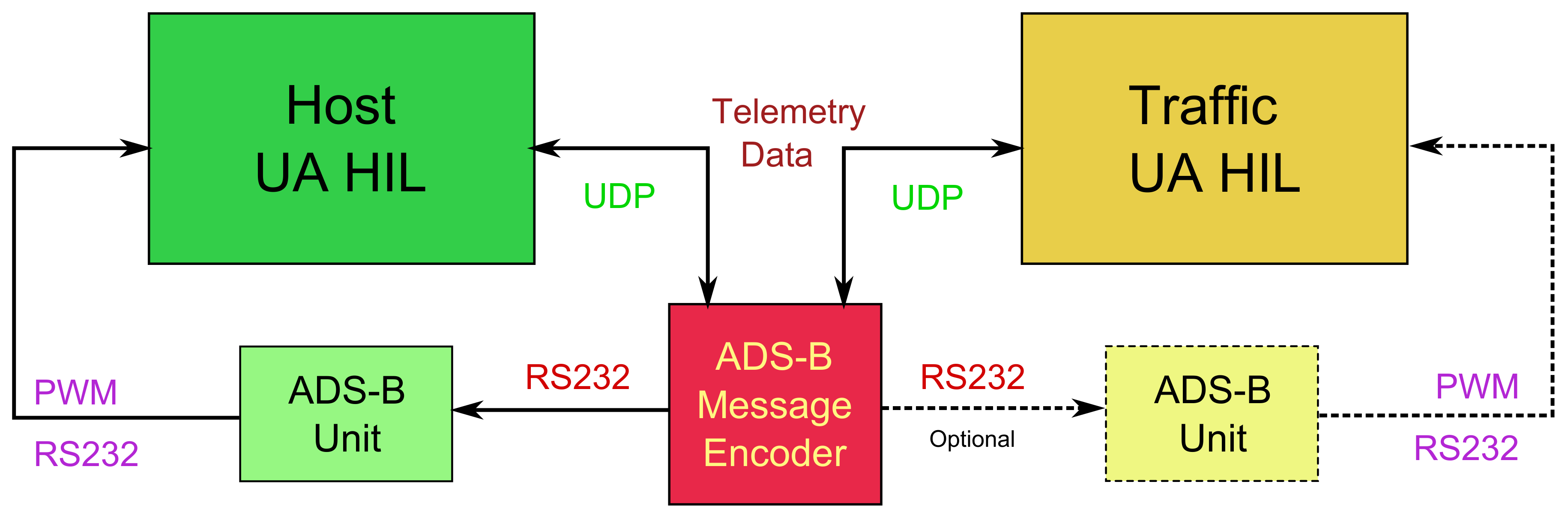
To improve the efficiency of BVLOS flight operations, an HIL testing platform was designed and constructed in the RAVEN project lab to help the PIC to carry out mission preparation, procedure training, and DAA system tests before field tests. As shown in Figure 14, real-time aircraft telemetry data from two separate HIL simulators (i.e., host UA and traffic UA) are fed into the ADS-B message encoder and converted into real-time ADS-B messages. ADS-B units receive the ADS-B messages from the RS232 serial communication link instead of the 978/1090 MHz RF link. The PWM signals or RS232 data are the outputs from the ADS-B units that command the autopilot to control the host UA to make appropriate maneuvers if needed.
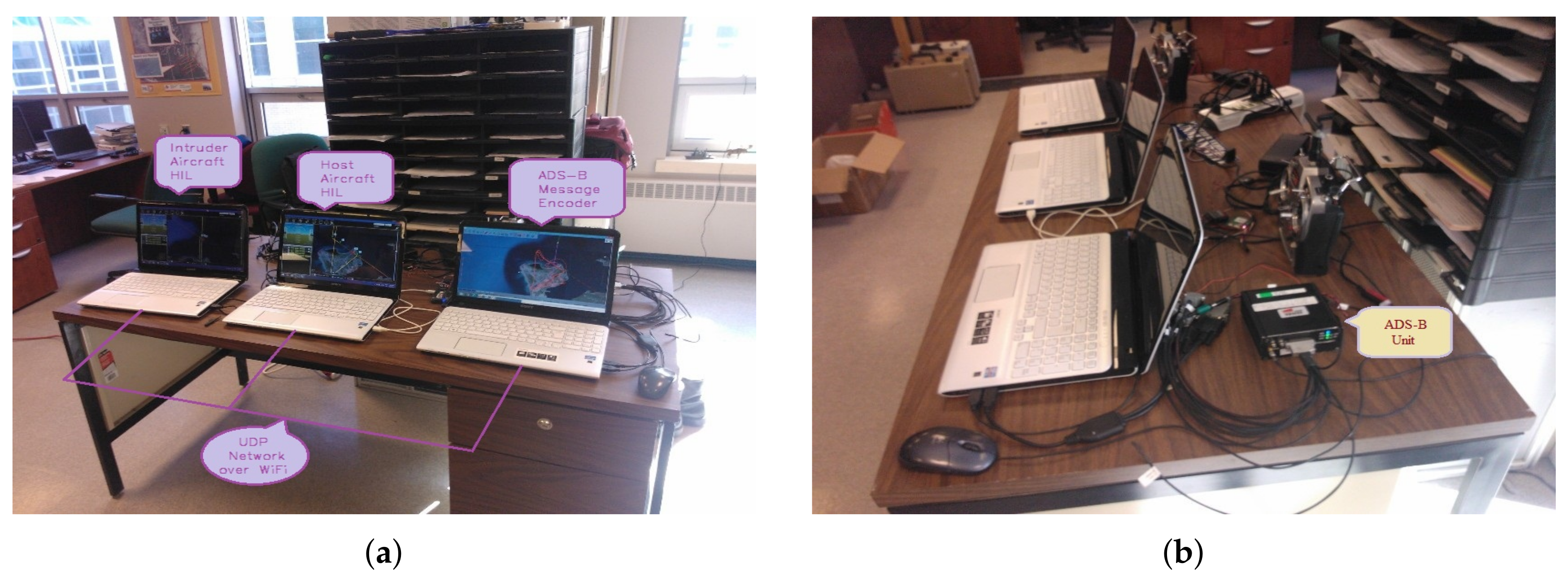
In Figure 15, the two laptops on the left are HIL systems for the host UA and the traffic UA, where the GCS software communicates with the autopilot and the simulated UA in FlightGear [19], a visualized aircraft model and flight environment simulator software. The ADS-B message encoder software is running on the laptop on the right, and this laptop is also used to display received ADS-B messages on the map where two UA are flying. With this HIL testing platform, the PIC can design, test and verify flight plans, and learn and practise emergency procedures for BVLOS flights in the field.
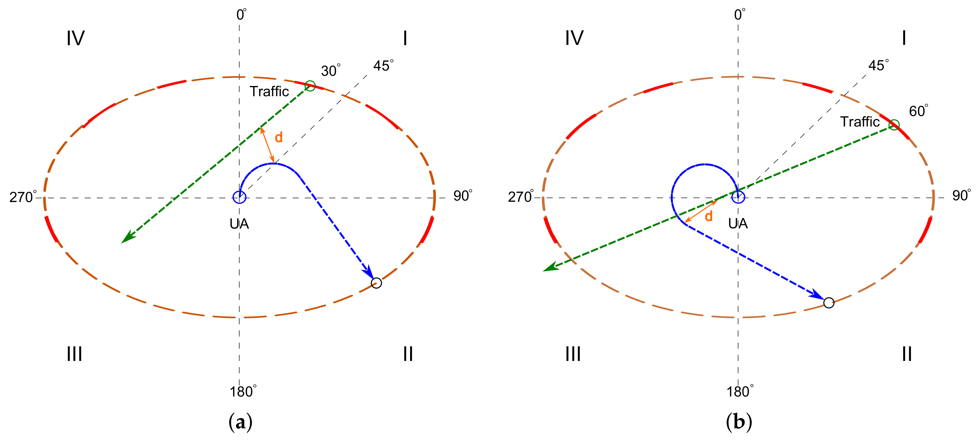
Thousands of NMAC encounters in a variety of geometries have been performed on the HIL testing platform with excellent avoidance performance. During DAA HIL tests, most vulnerable mid-air encounters occur when traffic UA emerge from three pairs of symmetric bearing regions on the UA CAAT boundary as the red arcs marked in Figure 16 (i.e., 30° ± 10° and 60° ± 10° in Quadrant I, 110° ± 10° in Quadrant II, 250° ± 10° in Quadrant III, as well as 330° ± 10° and 300° ± 10° in Quadrant IV), which are in accordance with the MC simulation results obtained in Figure 11b.
5. Results from BVLOS Flight Tests
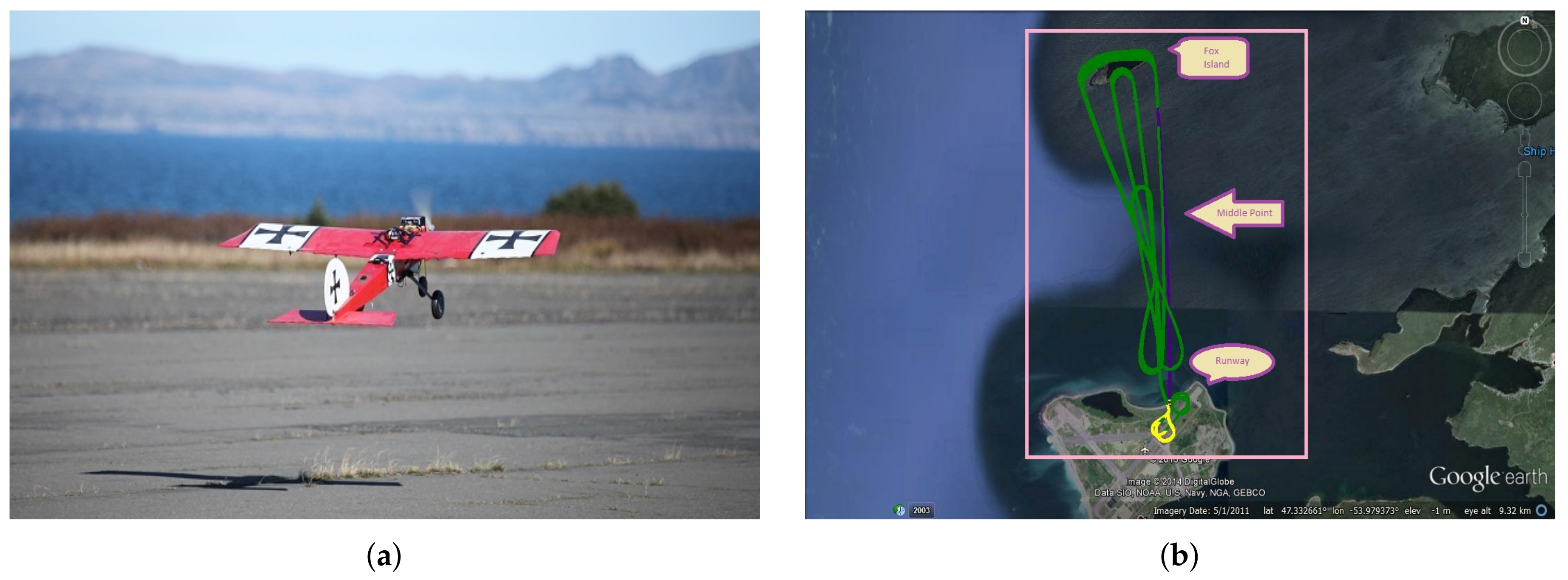
Figure 17a shows the take-off of a RAVEN Giant BigStik UA. The ADS-B box is mounted on the upper nose of the aircraft. As the flight logs show in Figure 17b, BVLOS flights are conducted in round-trips between the take-off point on the runway and Fox Island in Placentia Bay, a distance of approximately 7 km each way. The cruise altitude achieved is approximately 400 m above MSL. During BVLOS flights, the UA can only be seen during takeoff and landing at the runway area. Once the UA climbs to above 200 m, the PIC and other UAS ground operators have to rely on the autopilot C2 link and the FPV video link to monitor the attitude (roll, pitch, and yaw), position (latitude, longitude, and altitude), and status of the UA at the GCS, and control the UA to complete the flight missions for the RAVEN BVLOS research on the development of the proposed small UAS DAA system.
6. Summary and Conclusions
In this paper, the RAVEN project has designed and developed a set of extra safety features for BVLOS flight operations, such as extended communication links, an FPV video system, and a flight termination system with Geo-fence/RTL functions enabled in the autopilot to prevent UAS from flying away. Specially, a small UAS DAA system has been developed to help the PIC identify hazards and trigger avoidance maneuvers before a NMAC occurs. Furthermore, small UAS BVLOS operating procedures have also been developed and discussed in normal BVLOS operations and link-loss emergencies. The BVLOS flight tests carried out on the HIL testing platform and in the field show that the RAVEN-developed UAS safety systems can be employed to improve operational safety in small UAS BVLOS flight operations.
Acknowledgments
This work originated as part of Project RAVEN at Memorial University. Special thanks to all funding sources that supported this project over the years.
Author Contributions
S.X.F. and S.O. are responsible for all implementation, writing, and piloting for this project. S.O. and L.R. provided supervision, funding, and advice.
Conflicts of Interest
The authors declare no conflict of interest.
Abbreviations
The following abbreviations are used in this manuscript:
| ADC | Analog-to-Digital Converter |
| ADS-B | Automatic Dependent Surveillance-Broadcast |
| BVLOS | Beyond Visual Line of Sight |
| C2 | Command and Control |
| CPA | Closest Point of Approach |
| COA | Certificates of Waiver or Authorization |
| DAA | Detect and Avoid |
| FAA | Federal Aviation Administration |
| FPV | First Person View |
| GA | General Aviation |
| GCS | Ground Control Station |
| HIL | Hardware-In-Loop |
| MSL | Mean Sea Level |
| PIC | Pilot-In-Command |
| PWM | Pulse Width Modulation |
| PTA | Practice Target Area |
| RF | Radio Frequency |
| R/C | Radio Control |
| RTL | Return to Launch |
| SFOC | Special Flight Operations Certificates |
| SOP | Standard Operating Procedure |
| SWaP | Size, Weight, and Power |
| TC | Transport Canada |
| TCAS | Traffic Collision Avoidance System |
| UA | Unmanned Aircraft |
| UAS | Unmanned Aircraft Systems |
| US | United States |
| VLOS | Visual Line of Sight |
Appendix A
The Aerosonde UAS were developed for meteorological and environmental reconnaissance over oceanic and remote areas in a wide range of harsh weather conditions. They were the first UAS used to complete a trans-Atlantic flight in 1998 from the Bell Island, St. John’s, NL, Canada to the Outer Hebrides Islands, Scotland, UK, in 26 h and 45 min [20].
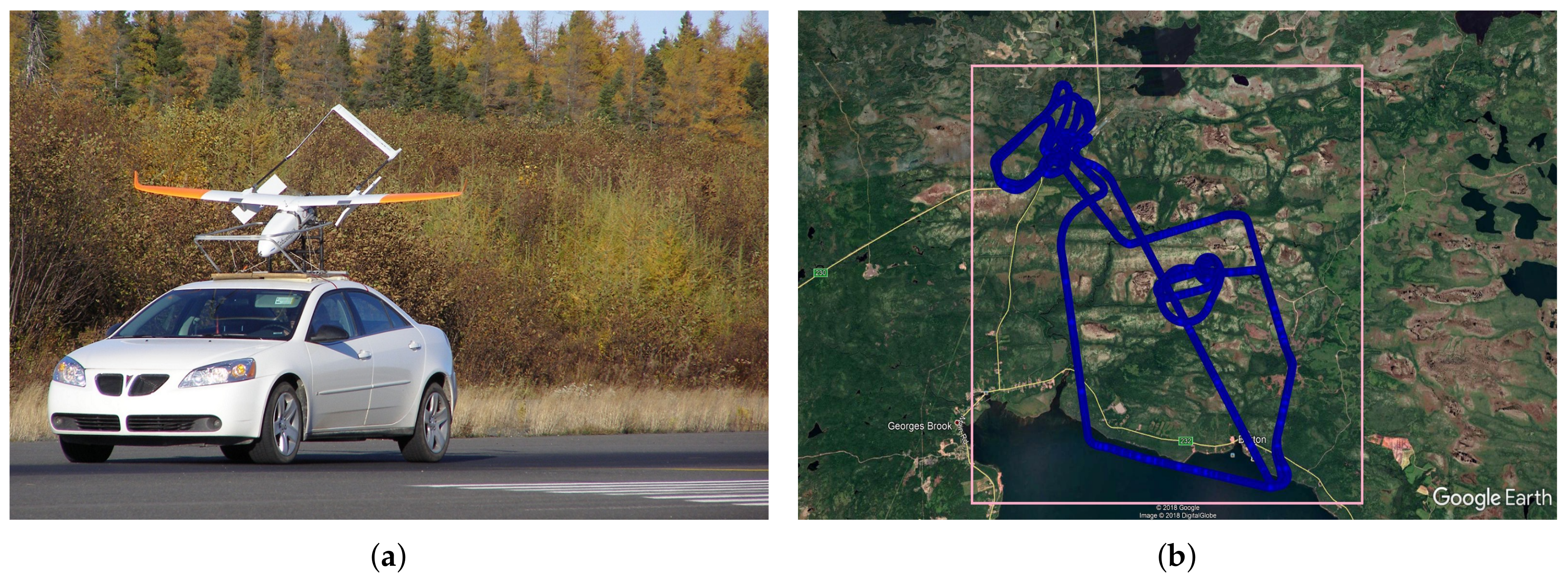
The RAVEN project acquired two Aerosonde UAS in 2006 (in Figure A1a) and carried out a series of BVLOS missions at the Clarenville—Random Island area, in Clarenville, NL, Canada for the environment monitoring research work in the region. As the flight logs show in Figure A1b, BVLOS flights are conducted in a rectangle region (6 km by 7 km), a total travel distance of approximately 60 km with the cruise altitude at 600 m above MSL.
Figure A1.
BVLOS flights at the Clarenville—Random Island area in Clarenville, NL, Canada. (a) Aerosonde Mk4.2 UA; (b) Logged Trajectories.
Figure A1.
BVLOS flights at the Clarenville—Random Island area in Clarenville, NL, Canada. (a) Aerosonde Mk4.2 UA; (b) Logged Trajectories.

References
- Limnaios, G.; Tsourveloudis, N.; Valavanis, K.P. Sense and Avoid in UAS: Chapter 1 Introduction. In Sense and Avoid in UAS; John Wiley & Sons, Ltd.: Hoboken, NJ, USA, 2012; pp. 1–34. [Google Scholar]
- Cox, T.; Nagy, C.; Skoog, M.; Somers, I. Civil UAV Capabilities Assessment; Technical Report; National Aeronautics and Space Administration: Washington, DC, USA, 2004.
- Federal Aviation Administration (FAA). Sense and Avoid (SAA) for Unmanned Aircraft Systems (UAS); Technical Report; FAA: Washington, DC, USA, 2009.
- Fasano, G.; Accado, D.; Moccia, A.; Moroney, D. Sense and avoid for unmanned aircraft systems. IEEE Aerosp. Electron. Syst. Mag. 2016, 31, 82–110. [Google Scholar] [CrossRef]
- Federal Aviation Administration (FAA). Request a Part 107 Waiver or Operation in Controlled Airspace; FAA: Washington, DC, USA, 2018.
- Transport Canada (TC). Staff Instruction; Document No: SI 623-001; TC: Ottawa, ON, Canada, 2017. [Google Scholar]
- Federal Aviation Administration (FAA). Certificates of Waiver or Authorization (COA); FAA: Washington, DC, USA, 2017.
- Transport Canada (TC). Applying for a Special Flight Operations Certificate; TC: Ottawa, ON, Canada, 2017.
- Radio Technical Commission for Aeronautics (RTCA). Minimum Operational Performance Standards (MOPS) for Detect and Avoid (DAA) Systems; Document No: RTCA/DO-365; RTCA, Inc.: Washington, DC, USA, 2017. [Google Scholar]
- Fang, S.X.; O’Young, S. Beyond Line of Sight (BLOS) Flight Mission Technical Report; Technical Report, Raven Project; Memorial University of Newfoundland: St. John’s, NL, Canada, 2014. [Google Scholar]
- Fang, S.X.; O’Young, S. Flight Termination System Technical Report; Technical Report, Raven Project; Memorial University of Newfoundland: St. John’s, NL, Canada, 2014. [Google Scholar]
- Balage, D.; O’Young, S. First Person View (FPV) System Technical Report; Technical Report, Raven Project; Memorial University of Newfoundland: St. John’s, NL, Canada, 2014. [Google Scholar]
- Geo-Fencing in Plane; ArduPilot Dev Team: Berkeley, CA, USA, 2018.
- Fang, S.X.; O’Young, S. ADS-B Based Cooperative Autonomous Collision Avoidance System (ACAS) Technical Report; Technical Report, Raven Project; Memorial University of Newfoundland: St. John’s, NL, Canada, 2014. [Google Scholar]
- Fang, S.X.; Rolland, L.; O’Young, S. Development and Implementation of ADS-B Based Cooperative Autonomous Collision Avoidance System. In Proceedings of the Unmanned Systems Canada Conference, Montreal, QC, Canada, 4–6 November 2014. [Google Scholar]
- Rouse, C. SEM Sensor TECH Project: Zeus Radar Test Report; Technical Report; Seamatica Aerospace Limited: St. John’s, NL, Canada, 2016. [Google Scholar]
- Zeus Radar System; Seamatica Aerospace Limited: St. John’s, NL, Canada, 2016.
- Fang, S.X. Risk-Based Supervisory Guidance for Detect and Avoid Involving Small Unmanned Aircraft Systems. Ph.D. Thesis, Memorial University, St. John’s, NL, Canada, 2018. [Google Scholar]
- FlightGear Flight Simulator; FlightGear Project: Minneapolis, MN, USA, 2017.
- McGeer, T. Laima: The First Atlantic Crossing by Unmanned Aircraft; The Insitu Group: Bingen, WA, USA, 1999. [Google Scholar]
Figure 1.
Map for the Argentia BVLOS operating area, Newfoundland, Canada.

Figure 2.
System configuration for small UAS DAA system tests in BVLOS flight operations.
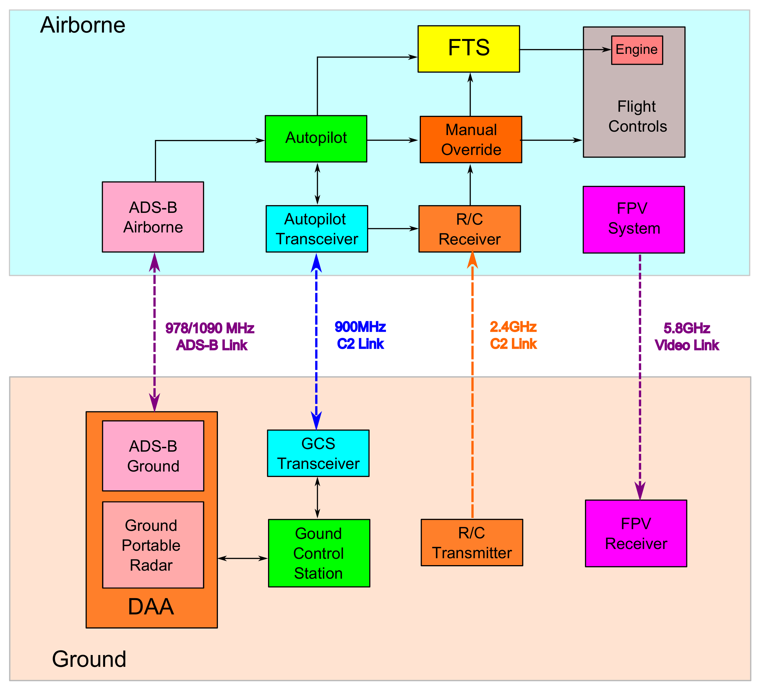
Figure 3.
The high-gain antennas used in BVLOS flight operations.

Figure 4.
A finished print circuit board for the FTS.
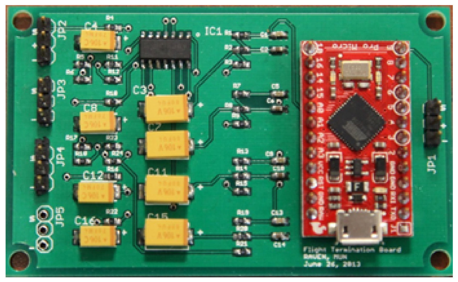
Figure 5.
Block diagram for flight termination system.

Figure 6.
Block diagrams for the FPV system. (a) FPV airborne side; (b) FPV ground side.

Figure 7.
Geo-fencing setup in the autopilot [13]. (a) Geo Fence in a Box; (b) Example Flight.
Figure 7.
Geo-fencing setup in the autopilot [13]. (a) Geo Fence in a Box; (b) Example Flight.

Figure 8.
Block diagram for the RAVEN-proposed small UAS DAA system.

Figure 9.
ADS-B and ground portable radar assembly. (a) AWSAS box; (b) Zeus without radome [17].
Figure 9.
ADS-B and ground portable radar assembly. (a) AWSAS box; (b) Zeus without radome [17].

Figure 10.
Diagrams to locate CAAT boundaries (bearing in deg and range in nmi). (a) Alerting threshold boundaries; (b) Simulation web structure.
Figure 10.
Diagrams to locate CAAT boundaries (bearing in deg and range in nmi). (a) Alerting threshold boundaries; (b) Simulation web structure.

Figure 11.
Summarized CAAT boundaries (bearing in deg, range in nmi, UA at 75 kt, and traffic at various airspeeds). (a) CAAT obtained without wind; (b) Summarized with various 20 kt gusty winds.
Figure 11.
Summarized CAAT boundaries (bearing in deg, range in nmi, UA at 75 kt, and traffic at various airspeeds). (a) CAAT obtained without wind; (b) Summarized with various 20 kt gusty winds.

Figure 12.
Horizontal maneuvering strategies in the three-dimensional evasive maneuvering algorithm.
Figure 12.
Horizontal maneuvering strategies in the three-dimensional evasive maneuvering algorithm.

Figure 13.
Horizontal maneuvering strategies in quadrant I, II, III, and IV. (a) Break-in bearing < 45° in quadrant I; (b) Break-in bearing > 45° in quadrant I; (c) Break-in bearing locations in quadrant II; (d) Break-in bearing locations in quadrant III; (e) Break-in bearing > 315° in quadrant IV; (f) Break-in bearing < 315° in quadrant IV.

Figure 14.
The HIL testing platform schematic diagram.

Figure 15.
The HIL testing platform in the lab. (a) Front View; (b) Side View.

Figure 16.
Diagrams for most vulnerable mid-air encounters during DAA HIL tests. (a) Traffic at 30° in Quadrant I; (b) Traffic at 60° in Quadrant I.
Figure 16.
Diagrams for most vulnerable mid-air encounters during DAA HIL tests. (a) Traffic at 30° in Quadrant I; (b) Traffic at 60° in Quadrant I.

Figure 17.
BVLOS flights at the RAVEN test site in Argentia, NL, Canada. (a) Giant BigStik UA; (b) Logged Trajectories.
Figure 17.
BVLOS flights at the RAVEN test site in Argentia, NL, Canada. (a) Giant BigStik UA; (b) Logged Trajectories.


Table 1.
High-gain antenna specifications.
| No | Antenna | Description |
|---|---|---|
| 1 | 900 MHz High-Gain Antenna | Supplier: L-COM Global Connectivity, Item No: HG8915EG, Specifications: 824–960 MHz, 50 Ohm, 15 dBi gain with 18° horizontal and 30° vertical beam width and VSWR < 1.5 |
| 2 | 5.8 GHz High-Gain Antenna | Supplier: L-COM Global Connectivity, Item No: HG5827EG, Specifications: 5.8 GHz, 50 Ohm, 27 dBi gain with 6° horizontal and 9° vertical beam width and VSWR < 1.5 |
Table 2.
Vertical maneuvering strategy.
| Geometric Classification | Action | Diagram |
|---|---|---|
| Traffic above UA | UA descending | 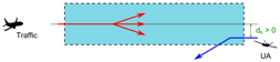 |
| Traffic below UA | UA climbing | 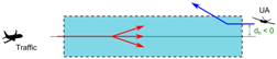 |
| Co-altitude and traffic climbing and | UA descending | 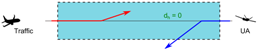 |
| Co-altitude and traffic levelling and | UA descending | 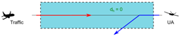 |
| Co-altitude and traffic descending and | UA climbing | 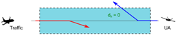 |
Table 3.
Link-loss failure cases in BVLOS flights.
| Case | R/C Link | AP Link | FPV Link | ACTION |
|---|---|---|---|---|
| Case 1 | ✓ | ✓ | ✓ |
|
| Case 2 | ✗ | ✗ | ✓ |
|
| Case 3 | ✗ | ✗ | ✗ |
|
| Case 4 | ✓ | ✓ | ✗ |
|
| Case 5 | ✗ | ✓ | ✓ |
|
| Case 6 | ✗ | ✓ | ✗ |
|
| Case 7 | ✓ | ✗ | ✓ |
|
| Case 8 | ✓ | ✗ | ✗ |
|
© 2018 by the authors. Licensee MDPI, Basel, Switzerland. This article is an open access article distributed under the terms and conditions of the Creative Commons Attribution (CC BY) license (http://creativecommons.org/licenses/by/4.0/).
Share and Cite
MDPI and ACS Style
Fang, S.X.; O’Young, S.; Rolland, L. Development of Small UAS Beyond-Visual-Line-of-Sight (BVLOS) Flight Operations: System Requirements and Procedures. Drones 2018, 2, 13. https://doi.org/10.3390/drones2020013
AMA Style
Fang SX, O’Young S, Rolland L. Development of Small UAS Beyond-Visual-Line-of-Sight (BVLOS) Flight Operations: System Requirements and Procedures. Drones. 2018; 2(2):13. https://doi.org/10.3390/drones2020013
Chicago/Turabian StyleFang, Scott Xiang, Siu O’Young, and Luc Rolland. 2018. "Development of Small UAS Beyond-Visual-Line-of-Sight (BVLOS) Flight Operations: System Requirements and Procedures" Drones 2, no. 2: 13. https://doi.org/10.3390/drones2020013