1. Introduction
Design and development, supported by computational power, are already applied in the optimization of robotic systems [
1]. Hazardous environments involve the usage of robotic applications for the detection of combat-mines, explosives, and dangerous materials to save lives and to protect the health of civilians and personnel engaged in decontamination. Applied solutions concerning robotic systems for quasi-autonomous inspections [
2], dangerous material detection/measurement [
3], harshness assessment [
4], personal safety [
5], automated controlled vehicles [
6], and Strengths, Weaknesses, Opportunities, and Threats (SWOT) analysis of the development processes [
7] have been partially approached, and applied in laboratory research. They also have been field-tested in given conditions to some extent [
8,
9]. Dangerous fields, such as postwar areas, roads, agricultural terrains, and accident sites with fatal casualties, are seen to be the beneficiaries of remotely controlled robotic applications. If combat-mines or sharp or cutting metals exist in the surface soil, then that field has a high degree of risk potential in other civil applications (injury may occur and fatalities and bodily integrity threats are possible). Analyzing applied data from cross-sectional testing of operational parameters is a request in the fields of vehicle use, terrain exploration, and other utility equipment [
10]. Studies of smart control of the operational systems installed on the utility vehicles [
11], and the optimal planning of displacement, in the case of mobile robots, using mathematical algorithms [
12] as well as Arduino and other platforms [
13,
14,
15], were applied for specific propulsion and robot-in-the-loop coordination [
16]. Resource protection and security are two of the main objectives for these kinds of developments. Enhanced power sources are a key factor [
17] for autonomous robotic vehicles [
18] in hazardous scenarios [
19].
The primary objectives of the present paper include designing an all-terrain intelligent robotic vehicle (ATIRV); developing of a low-cost model for metal detection; studying the faults, challenges, and vulnerabilities of the laboratory model; extending the capabilities of the laboratory work to the real-size vehicle; and presenting the first test results. The ATIRV design process, development, and testing sequences cover aspects regarding multiple operating modes (such as accelerate, drive, brake, decelerate, and detect), as well as engineering innovation solutions for reaching the primary objective of research. This research addresses problems and aspects related to designing, programming, sensor installation, remote digital management, vehicle electronic control, actuator structures, and multiple practical testing (both in laboratory conditions with a low-cost mini-model and in the field scenario with a real-size all-terrain vehicle). These scenarios have been made to verify the physical platform and the predefined algorithms for automated driving. Challenges, faults, and vulnerabilities of the robotic models were also closely monitored during the design and development process. The intelligent components installed in this application consist in fuzzy regulators which are used in the vehicle’s control part. First, a virtual reality model for an experimental mobile robot with field exploration and detection capabilities was created. Second, the mini-model for laboratory testing was realized. The third phase presented the real-size vehicle dynamic field testing in which the programming and digital control were applied to an actual All-Terrain Vehicle (ATV) for data recording and scientific study of the problem. The main tasks of ATIRVs are field exploration and the detection of metal objects (like combat-mines).
2. Materials and Designing Method
The applied scientific work is supported by an adaptable design of an automated robotic all-terrain vehicle that is designed to detect specific objects in broken or hazardous terrains. Considering these aspects is a quite often debated and defined problem in robotics and mechatronics, especially when high mobility or autonomy is required. Significant demands for this kind of robotic applications are also taken into consideration in domains regarding victim assistance, complex fires, atomic hazards, and space exploration. During the sequence of ATIRV designing and project development, engineering-specialized programs (such as Unity 5, MATLAB/Simulink, AutoCAD, and SolidWorks) were used to study both the one-degree model and the all-terrain-wheeled robot with mathematical equation systems.
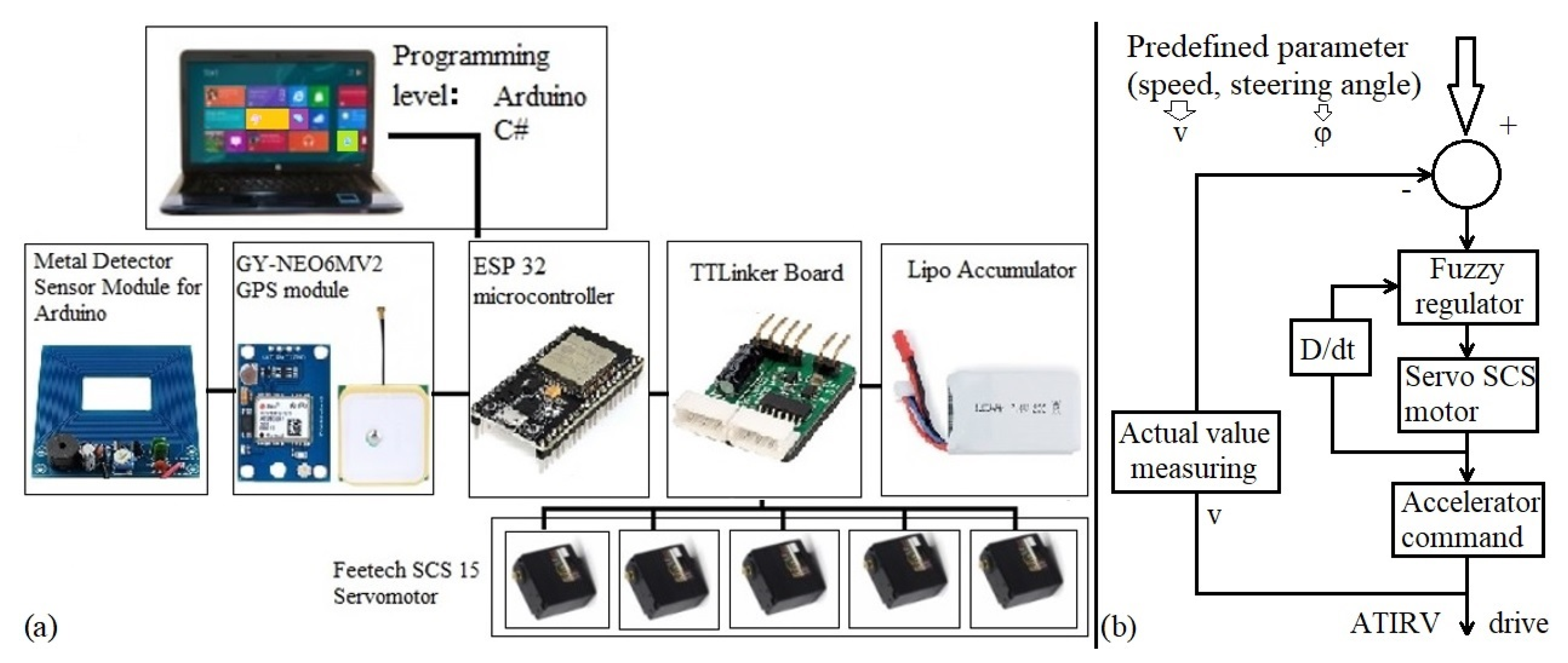
A series of calculations and programming were done to determine and control the operational dynamic parameters related to robotic vehicles by using a digital platform. A simple diagram with the connections of the components is shown in
Figure 1.
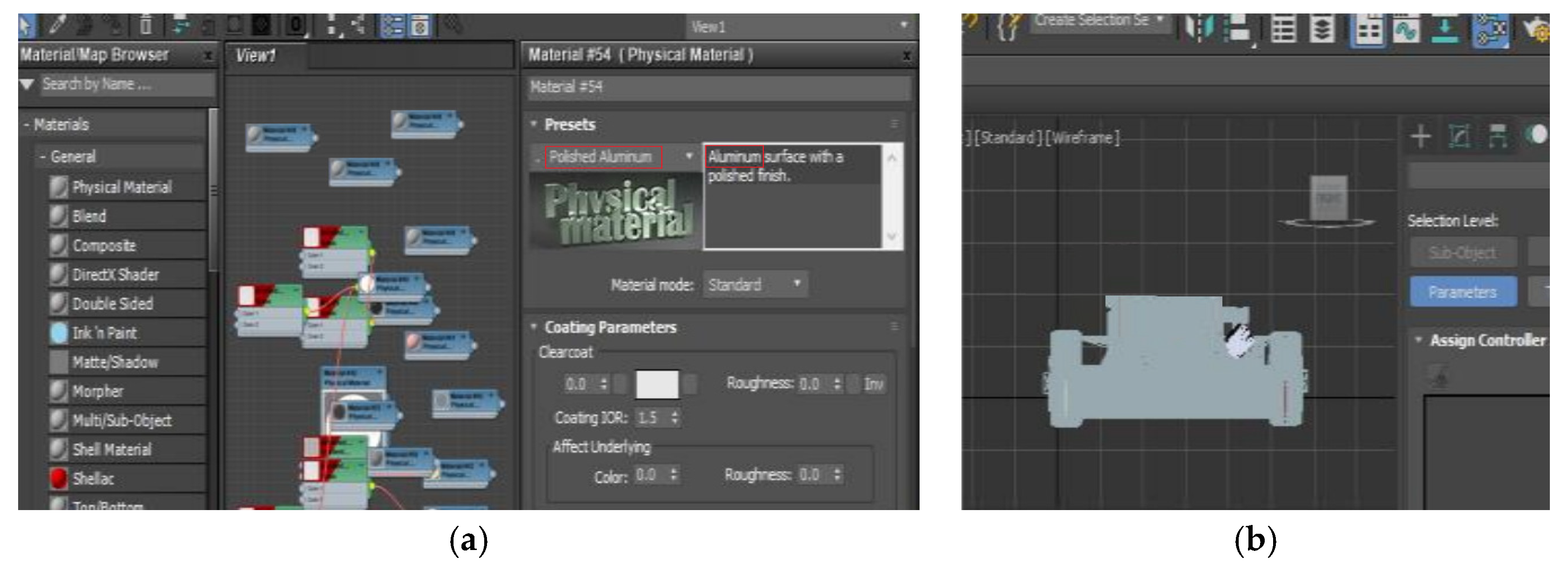
Virtual reality (VR) is the cutting edge of technology development. Using VR tools facilitates the experimentation of a new reality (that does not exist in material world). It is used in important applications (such as the ones mentioned and proposed in the present paper). Part of the design for ATIRVs is supported by the Siemens NX program. In the first place, the robot’s platform was generated. This was provided with “home position” for the robotic arm, headlights, energy source, and antenna. After the virtual creation of the robot’s platform, the wheel train was designed. Then the components were assembled and a format conversion was made to facilitate implementation in the virtual reality. After the 3D construction and virtual modeling of the mobile robot, it was imported into the Unity 5 environment, which supports specific formats and extensions such as “3ds”, “dae”, “dxf”, “fbx”, “obj”, and “skp”. The next step was to assign material properties to the components of the mobile robot in the Keyshot program. The main challenge was the size of the resulting file, which was considerably large. Due to the problems in using such a volume-demanding format, the alternative 3ds Max program became appealing. This software solution allowed complex 3D modeling, animation, rendering, and graphical composition in motion. All the components must be verified in 3ds Max to have a correct load. Other faults and challenges were found in the fact that the 3ds Max program did not keep the restraints from Siemens NX. The positions of the axles were, at this point, misplaced. Beside all the designing process, one specific innovation was the solution for aligning all the axles in the correct positions. We assigned coordinates to each part of axis. Then we replaced all the axles of components according to the topological data from Siemens NX, obtaining in this manner the correct positions of the corresponding components. This was done by selecting the specific part from 3ds Max, entering the pivot menu, and changing the axis position. After assigning physical material to each component, the importation process needed to be realized into the Unity 5 application.
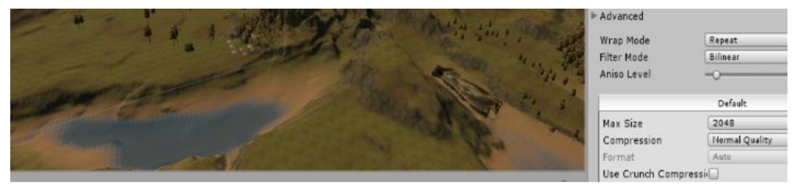
An important step in the design and virtual development of the ATIRV consisted in material assignation and rendering from wireframe and coating parameter definition, as shown in
Figure 2.
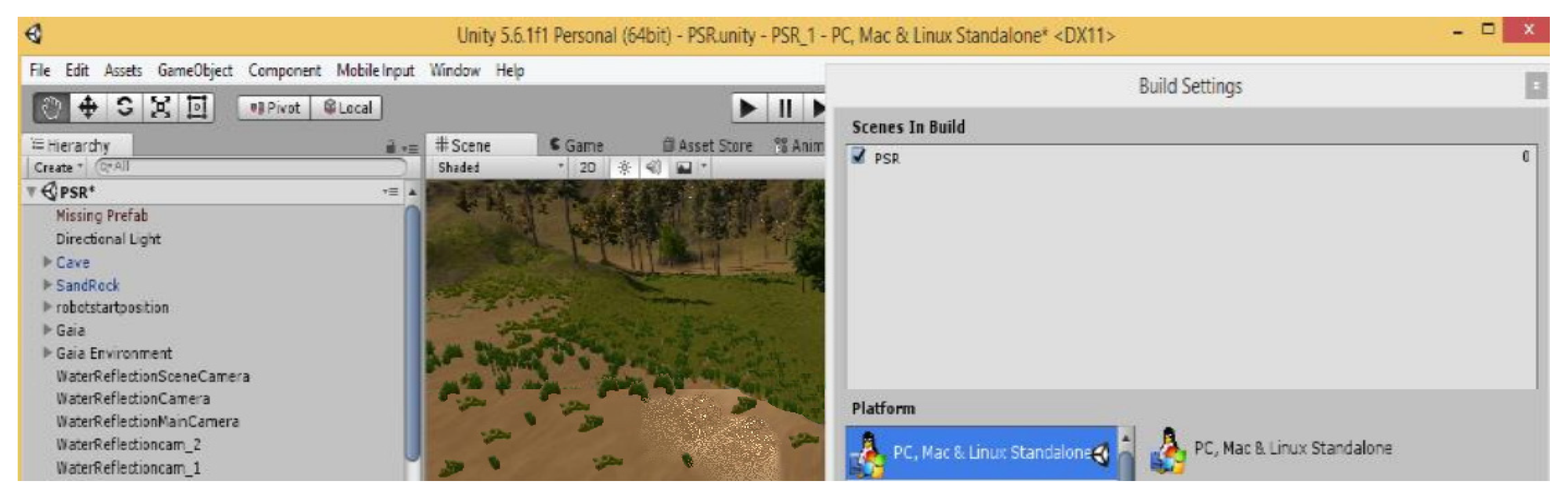
The Unity 5 environment is used for 3D games and VR simulators, allowing 3 programming codes (C#, JavaScript, and Boo) and exporting capabilities for multiple operating systems. Prior to ATIRV import into the Unity 5 application, a textured environment was generated using the Gaia program, which allows the creation of vegetation, water, and rocks (of different sizes and shapes), as shown in
Figure 3.
The Unity 5 application may be generated for different types of operating systems (Android, iOS, Linux, Mac, PC, PS4, Xbox, etc.), as shown in
Figure 4.
With the support of the developed virtual model, a laboratory mobile mini-robot was realized to test similar features, such as detection and exploration, for the ATIRV. The software application facilitated the virtual modeling of different robotic mechanisms. Robotic design allowed an improved control of the automation suitable processes. The design and development of the lab model was strongly facilitated by the virtual construction of the automated vehicle. The virtual model may be designed and simulated on the same computer station, but the physical model has two distinctive control units, one being the server (at the programming level) and the other being the client Espressif Systems Part (ESP 32 micro-controller).
The electronic control unit acquires all the signals and information from the transferring module once the transfer procedure is complete and will send the signals toward the powertrain assembly to drive the ATIRV to the new defined location. In relation to the physical road track, the method of detecting and following the magnetic material lane is very efficient and reliable in this type of robotic application for reaching the expected outcome and proper results. The optimal driving track lane is realized when taking into consideration all the aspects and vulnerabilities that may occur. The ATIRV was a battery-propelled electric vehicle which could charge with electricity automatically. To improve the ATIRV operational performance, inductive power transfer methods were applied.
Material components used by the present work consist in electronic software programs, command units, and physical actuators for controlling the automated vehicle (specific data regarding technical features are offered in
Table 1).
3. Development and Results
Proximity sensing transducers were installed in the robotic ATIRV driveway in order to gain information about the vehicle’s surrounding obstacles, kinetic actions, distances, and empty paths, the kinds of data which practically impose the starting and stopping sequences. Photometric transducers were set up to gain information concerning obstacles or objects on the track. A predefined object detection module was also provided, and a physical transfer system facilitated detection and deactivation of hazardous materials with a package of special mechatronic equipment, in which all electric and electronic connections were interdependent.
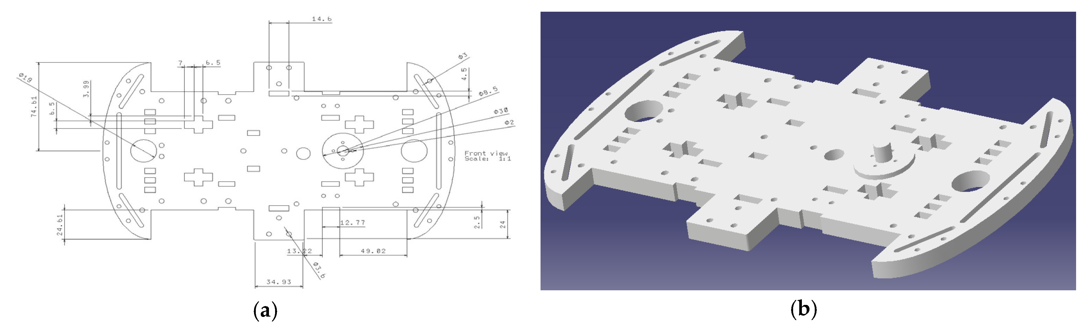
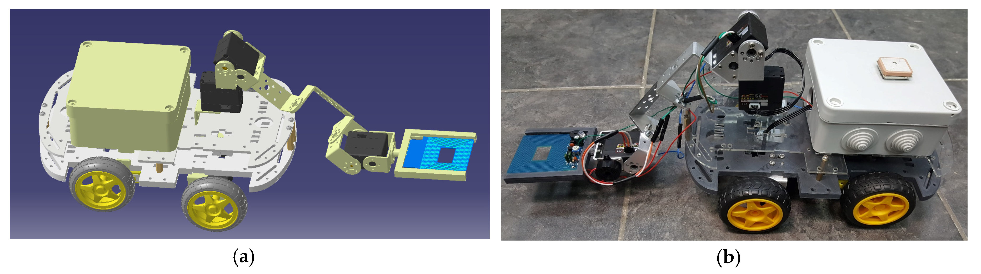
The first phase of development consisted in design, calculus of dimensions, and virtual development using Computer Aided Design (CAD) tools, as shown in
Figure 5.
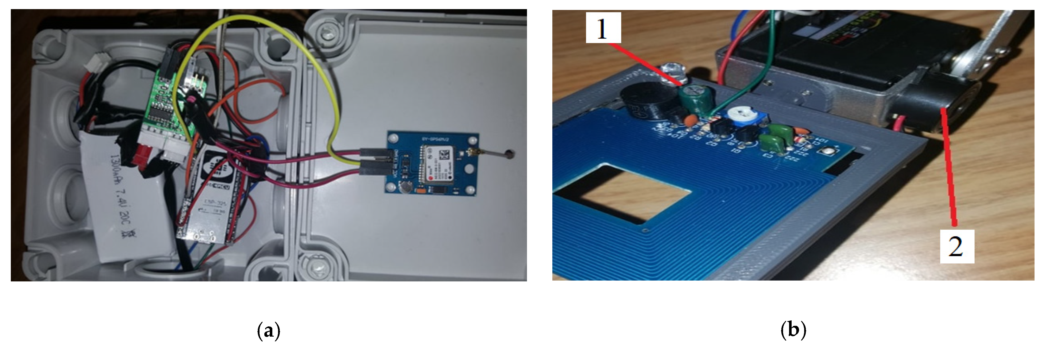
The second important phase consisted in material acquirement and wire connections. Electronic circuits and sensor connections were made to develop the detection system, which was provided with LED signaling lamp 1, for object presence, and signal amplifier 2, as shown in
Figure 6.
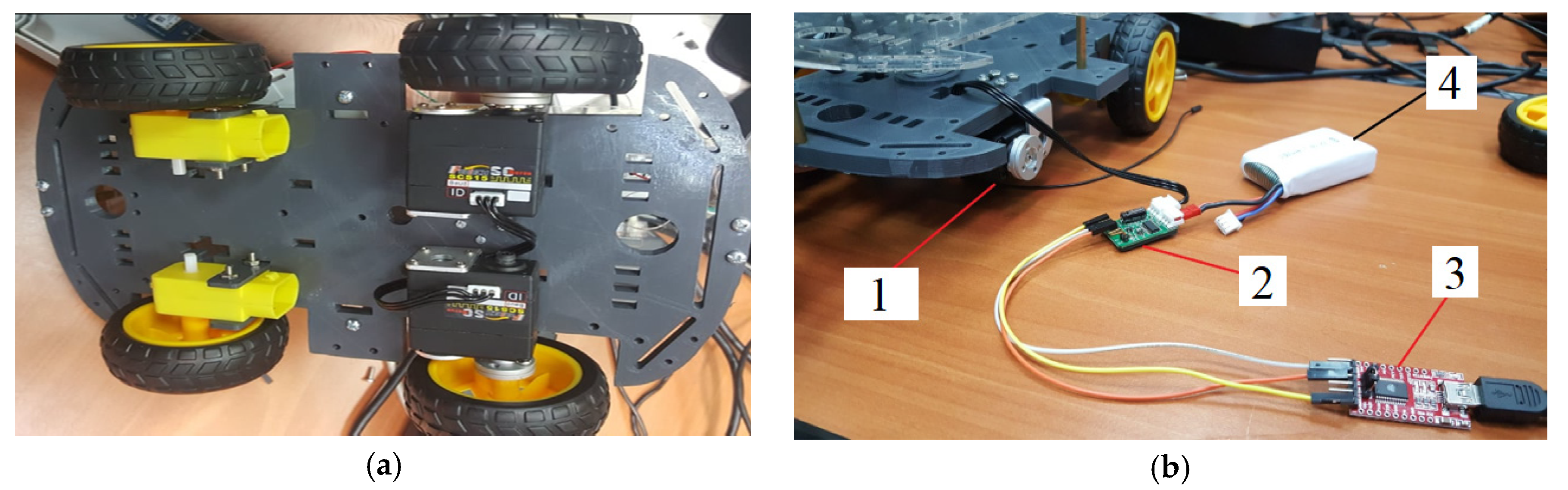
The third phase of the design and development process consisted in vehicle assembly (servomotor 1, TTLinker board 2, conversion board 3) and detection testing. For the power supply of the robot, a Lipo 7.4 V/1300 mA accumulator 4 was provided. The hardware structure was manufactured and assembled for ATIRV complete development and for power supply testing, as shown in
Figure 7.
A switch was added to turn the robot on whenever required and to turn it off when the detection task was completed, for energy conservation in the accumulator. One fault of the GPS module, which was outlined during the tests, consisted in the duration of about 15 min it took to establish satellite connection outdoor. Indoor, the connecting process became even harder, and it could take up to one hour. This made robot testing a challenge because we had to make the connection first, prior to running the detection program. In light of the above-mentioned problem, the robot’s antenna was installed above the plastic case of the electronic components, to facilitate satellite connection, as shown in
Figure 8.
The hardware platform we received with the Arduino kit and initially used had some major issues, a fact which contributed to the personalized design of the mobile robot. Thus, additional pockets were created in the platform to attach the servomotors for the front D65X28 wheels. Another adjustment we had to make was the creation of a section where we could attach the robotic detector tool, since the standard design version of the kit did not include such equipment. The final challenge was the acrylic plastic material of structural platform from the standard assembly because it would collapse under the weight and stress of the detector equipment. The power consumption was calculated using Equation (1).
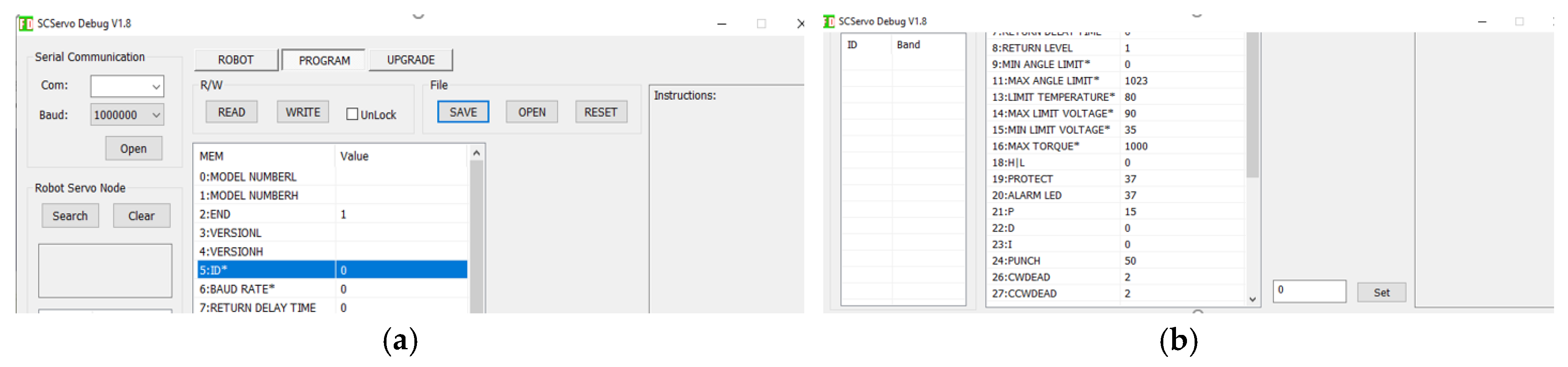
Using a software interface, the user can define specific IDs to each servomotor. The default ID is 0. To change the ID with this program the “unlock” checkbox on top must be clicked, the ID value in the corresponding field written, “set” pressed, and then “WRITE” hit. Additionally, the servo type may be set to servo-mode or to wheel mode, and many other pre-testing specifications may be set, by using script-fields and selection boxes for data input, as shown in
Figure 9.
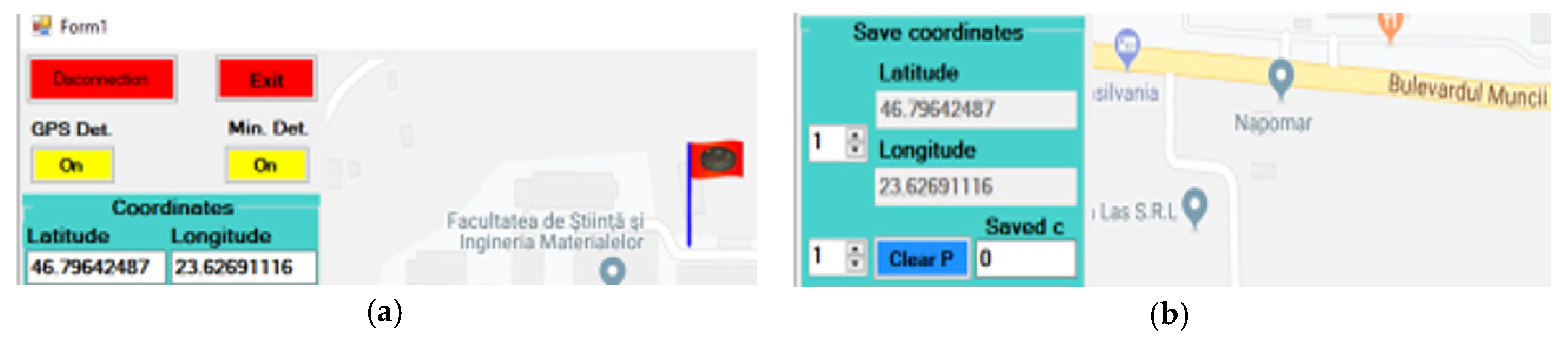
Microsoft Visual Studio 2017 was used for the design and development of the graphical user interface with map display system and client-server communication, as shown in
Figure 10.
The server in this case is on the PC station inside the control room and the client is on the mobile robot that is remotely driven through the smart application.
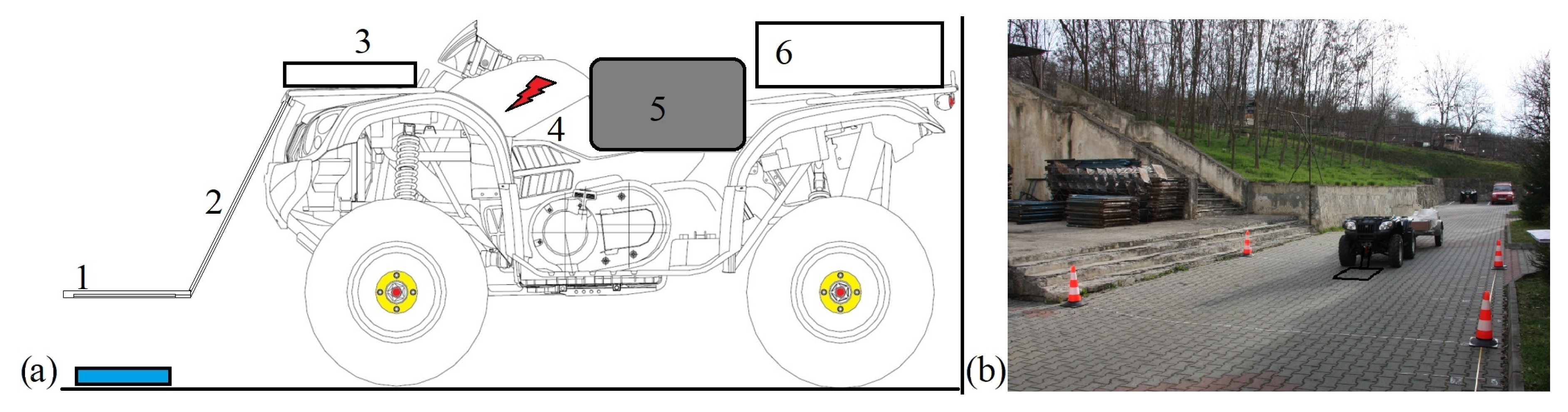
For experimental testing of the proposed idea was considered a research-prepared ATIRV, as shown in
Figure 11.
The hardware assembly we received with the experimental ATV kit and first used in testing had multiple major issues, a fact which contributed to the specialized design of the ATIRV. Thus, additional components were created and placed in the front of the vehicle to attach the metal detecting sensor, the wiring box, the GPS protection case, and the accumulator safety cover. Additionally, the ABS (Antilock Braking System) needed to be programmed as BAS (Braking Assist System) to improve stopping control of the wheels. Another contribution we had to make consisted of an adjustment where the metal detector sensor was attached, since the standard design version of the kit did not include such equipment. After solving the practical challenges, tests were performed.
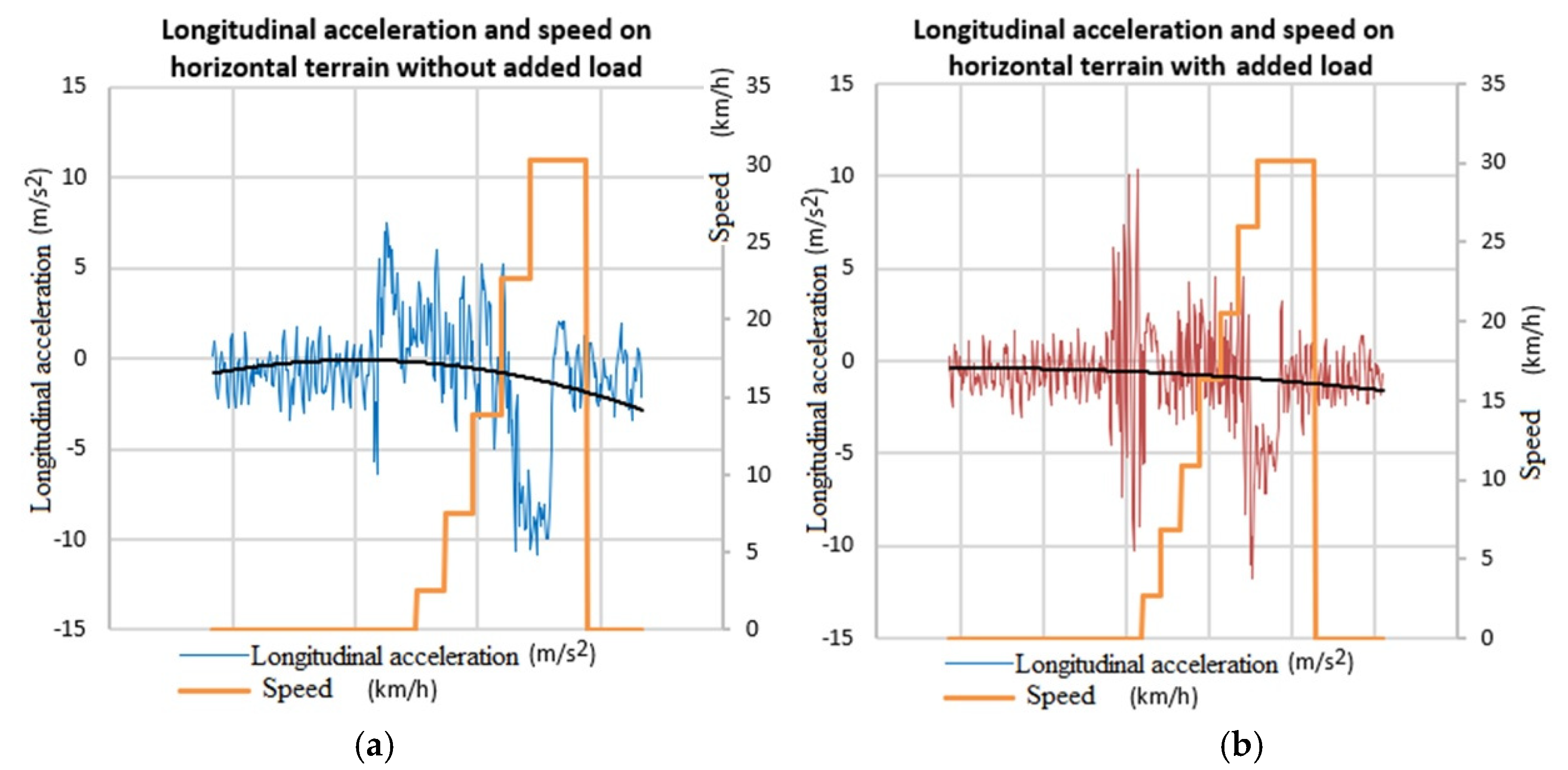
During the experimental testing, kinematic data were obtained by using GPS data and acceleration sensor, which are significant data of ATIRV operation.
Longitudinal accelerations and speed variations on horizontal terrain were graphically represented for two distinctive testing scenarios ((a) without any added load; (b) with a load of 1000 N), as shown in
Figure 12.
The actual values obtained in the process of experimental testing of the practically prepared ATIRV, without any added load, are offered in
Table 2.
The real values gained in the process of experimental testing of the practically configured ATIRV, with 1000 N added load, are offered in
Table 3.
The required power was defined using the following mathematical model to gain values:
where P is power consumption; F
i is inertial force, in Newtons; v is speed; and k is correction factor (k = 1.5).
4. Discussions and Conclusions
One of the significant innovative contributions of the present research consists in the physical developed vehicle, which is highly adaptable and has a great degree of flexibility, thus making it suitable to be implemented in multiple robotic applications and automotive architectures. The connectors, communication pathways, technical vulnerabilities, and safety aspects were also considered and evaluated. This work presented the design and results of control protocol for an all-terrain intelligent vehicle robot which may be applied in a multitude of scenarios, such as surveillance, hazardous transports, and metal detection, in both muddy and snowy surfaces. The ATIRV was designed to be electrically powered from a rechargeable battery package (to be used with a solar photo-voltaic panel charger) and most of the implemented actuators were electric motors. All the latter components were electronically controlled by integrated microprocessors monitored by the vehicle’s control unit. The ATIRV was equipped with eight high-resolution digital camera sensors, 3D scanners with laser technology, a special Inertial Control Unit (ICU), a digital compass, a GPS unit, a radio transceiver kit, and long-range wireless communication capability. The primary model of the ATIRV focused on first-level objectives such as specific detection, 3D all-terrain surveillance and mapping (on-road and off-road), basic driving styles, basic starting and stopping styles, avoiding obstacles like large rocks or stone blocks, and driving over off-road surfaces like highly fractured ground and hilly terrains. The detection tool performed specific maneuvers such as precise locating, searching, removing, or neutralizing if there were applied additional components. In relation to other research, such as on semi-autonomous robots [
2], this was intended to perform fully automated, even if there was a limit regarding the complete automation of the experimental kit to the present moment.
Still, the know-how transfer from laboratory mini-model to the real-size field ATIRV was a significant challenge. It required a precise control of kinematics and dynamics of the robotic vehicle. The propulsion and the braking needed to be properly managed and precisely monitored. A display and graphic presentation [
14] of the actual values were important in fast monitoring process.
Some descriptors in the process of designing the automated vehicle and from the SWOT analysis to study its faults and vulnerabilities are offered by
Table 4.
Development and research of automatic ATIRVs, using VR simulation and laboratory models, has significant importance in automation and robotics, Computer Aided Design/Computer Aided Manufacturing/Computer Aided Engineering (CAD/CAM/CAE) integrated systems, sensing and control, information systems technology, advanced software technology, intelligent systems and technologies, parallel and distributed computing technology, automotive engineering and transportation due to improvement of road and traffic safety, data processing techniques, and operational reliability in the coming years. In the present case, the proposed and tested ATIRV with an automatic guided driving program had a metal object detection system placed in the front part, a powertrain, and a steering system inside the vehicle’s structure to drive it optimally in a given scenario. The researched robot in the present study was a customized all-terrain intelligent guided vehicle that had the capacity to detect magnetic materials, but it could also be reconfigured for other specialized tasks. The ATIRV robot acted and drove independently and automatically on its own data as soon as the program was downloaded inside the electronic control unit. The electronic control unit was used for both powertrain and detecting system, which were interconnected. The electronic control unit drove the robotic vehicle and sustained the working process of the automated ATIRV. Compared to Havlik’s robotic tools for de-mining operations, the present work is still a progressing project, but there are some expectations for development.


